1
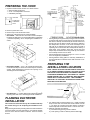
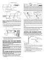
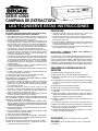
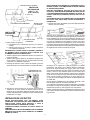
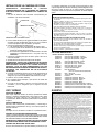
43000 SERIES
RANGE HOOD
READ AND SAVE THESE INSTRUCTIONS
WARNING
CAUTION
TO REDUCE THE RISK OF FIRE, ELECTRIC SHOCK, OR INJURY TO PERSONS, OBSERVE THE FOLLOWING:
1. Use this unit only in the manner intended by the manufacturer. If you have questions, contact the manufacturer at the
address or telephone number listed in the warranty.
2. Before servicing or cleaning unit, switch power off at service
panel and lock service panel to prevent power from being
switched on accidentally. When the service disconnecting
means cannot be locked, securely fasten a prominent warning device, such as a tag, to the service panel.
3. Installation work and electrical wiring must be done by a qualified person(s) in accordance with all applicable codes and standards.
4. Sufficient air is needed for proper combustion and exhausting
of gases through the flue (chimney) of fuel burning equipment
to prevent backdrafting. Follow the heating equipment
manufacturer’s guideline and safety standards such as those
published by the National Fire Protection Association (NFPA),
and the American Society for Heating, Refrigeration and Air
Conditioning Engineers (ASHRAE), and the local code authorities.
5. When cutting or drilling into wall or ceiling, do not damage
electrical wiring and other hidden utilities.
6. Ducted fans must always be vented to the outdoors.
7. Do not use this unit with any solid-state speed control device.
8. To reduce the risk of fire, use only metal ductwork.
9. This unit must be grounded.
TO REDUCE THE RISK OF A RANGE TOP GREASE FIRE:
1. Never leave surface units unattended at high settings.
Boilovers cause smoking and greasy spillovers that may
ignite. Heat oils slowly on low or medium settings.
2. Always turn hood ON when cooking at high heat or when
cooking flaming foods.
3. Clean ventilating fans frequently. Grease should not be
allowed to accumulate on fan or filter.
4. Use proper pan size. Always use cookware appropriate for
the size of the surface element.
TO REDUCE THE RISK OF INJURY TO PERSONS IN THE
EVENT OF A RANGE TOP GREASE FIRE, OBSERVE THE
FOLLOWING:*
1. SMOTHER FLAMES with a close-fitting lid, cookie sheet, or
metal tray, then turn off the burner. BE CAREFUL TO PREVENT BURNS. If the flames do not go out immediately,
EVACUATE AND CALL THE FIRE DEPARTMENT.
2. NEVER PICK UP A FLAMING PAN - You may be burned.
3. DO NOT USE WATER, including wet dishcloths or towels - a
violent steam explosion will result.
4. Use an extinguisher ONLY if:
A. You know you have a Class ABC extinguisher and you already
know how to operate it.
B. The fire is small and contained in the area where it started.
C. The fire department is being called.
D. You can fight the fire with your back to an exit.
*Based on “Kitchen Firesafety Tips” published by NFPA.
1. For general ventilating use only. Do not use to exhaust hazardous or explosive materials and vapors.
2. To avoid motor bearing damage and noisy and/or unbalanced
impellers, keep drywall spray, construction dust, etc. off power
unit.
3. For best capture of cooking impurities, your range hood should
be mounted 18-25” above the cooking surface.
4. Please read specification label on product for further information and requirements.
IMPORTANT: OBSERVE ALL GOVERNING CODES AND ORDINANCES
Your range hood has been designed to filter out smoke, odors,
and grease which rise from the cooking surface. Before you being the installation be sure that all parts and accessories are removed from carton. For best results and ease in the installation
of this range hood, read the instructions sheet to become familiar
with the step-by-step installation.
TOOLS AND MATERIALS
REQUIRED
q
q
q
q
Drill, electric or ratchet drive
1/8" drill bit for drilling pilot holes
1-1/4" wood bit for drilling electrical wiring access hole
One common head screwdriver for securing hood mounting
screws to the cabinet and hood sheet metal parts
q Pliers for opening knockouts
q Pencil, rule and level for marking cabinet locations
q Saber saw or keyhole saw for cutting the wall or cabinet openings
q Metal snips, duct tape, duct (with elbows and transition, if necessary), roof cement or caulk, and roof or wall cap, as required
q Electrical wiring and supplies of type to comply with local codes
The following materials are required only for installation on recessed bottom kitchen cabinets:
q Two 1" x 2" x 12" (approximate length) wood strips (purchase
locally)
q Four 1-1/4" long flat head wood screws (purchase locally)
INSTALLER:
LEAVE THIS MANUAL WITH THE HOMEOWNER.
HOMEOWNER:
USE AND CARE INSTRUCTIONS ON
PAGE 4.
PREPARING THE HOOD
ROOF CAP
ROOF CAP
1. Unpack hood and check contents. You should receive:
1 – Filter with built-in light lens
1 – 3-1/4" x 10" damper/duct connector
1 – Installation parts bag
BP87 DAMPER (NOT INCLUDED) LOCATED AT
LEAST 6" FROM HOOD
IN VERTICAL SECTION
OF DUCT
DAMPER
(INCLUDED)
LIGHT LENS
ALUMINUM OR
COMBINATION
FILTER
2.
3.
4.
•
REMOVE THE
HOOD DAMPER
FLAP IF IT
INTERFERES
WITH THE WALL
CAP DAMPER
JUNCTION BOX
Remove junction box cover.
Remove top or rear electrical knockout.
Select one of the three types of venting available:
Non-Vented — Remove vent cover from hood front. Replace
the aluminum filter with a non-ducted filter (BP57 or R610050
- purchase separately). Go to "Preparing the Installation Location".
• Ducting directly through the wall (for range hoods mounted on
an exterior wall). Shown are two ways to duct through an outside wall. If a wall cap is used directly off the back of the hood,
special care must be taken to make sure that the damper in
the damper/duct connector on the hood and damper in the
wall cap do not interfere with each other when the hood is
operating. This could result in either inadequate air delivery or
back drafts. If this condition does exist, remove the hood
damper flap. Sometimes when using a wall cap, it is easier to
duct vertically and then use an elbow.
• Ducting straight up through roof using 3-1/4" x 10" or 7" round
duct. For single story installations.
• Ducting between ceiling joists for multi-story installations or
through soffits above cabinets where soffit connects to outside walls.
VENT COVER
➁
➀
➂
PREPARING THE
INSTALLATION LOCATION
• Rectangular Vented — 3-1/4" x 10" vertical or horizontal. Remove knockout #➁ for vertical or knockout #➂ for horizontal
venting. Install damper/duct connector over opening. Go to
"Planning Ductwork Installation".
NOTE: MOUNT HOOD SO THAT BOTTOM OF HOOD IS 18"
TO 25" ABOVE COOKING SURFACE. TOP FRONT OF HOOD
SHOULD BE FLUSH WITH FRONT OF CABINET FRAME.
IF DISTANCE BETWEEN WALL AND FRONT OF CABINET
FRAME IS MORE THAN 12", THERE WILL BE A SPACE BETWEEN BACK OF HOOD AND WALL. THIS IS NORMAL.
OMIT STEP 1 IF HOOD WILL BE INSTALLED UNDER CABINETS WITH FLUSH BOTTOM.
FILLER STRIP
• Round Vented — 7" vertical. Remove knockouts #➀ and #➁
exposing duct collar. Go to "Planning Ductwork Installation".
PLANNING DUCTWORK
INSTALLATION
This section for vented hoods only. Non-vented hoods skip
this section and go on to "Preparing the Installation Location".
Begin planning ductwork by deciding where duct will run between
hood and outside. For best performance, use shortest possible
duct run and a minimum number of elbows. There are several
choices.
1. For cabinets with recessed bottoms only: Install wood filler
strips on each side of recessed area under cabinet. Use two
1" x 2" strips cut to length (use thicker strips if necessary).
Fasten strips with wood screws about 3" in from each end.
2. Measure and mark the following:
a.) Electrical wiring opening in wall or cabinet.
b.) Duct opening in wall or cabinet (vented hoods only).
2
CABINET CUTOUTS
3-1/4" x 10"
RECTANGULAR
VENTING
Wall Cap Discharge: Use saber saw or keyhole saw to cut hole
slightly larger than duct size used so that duct will line up easily
with damper/duct connector on hood. Install casing strips if cap
will be installed on siding. Attach required amount of duct to wall
cap and run duct back to hood. Fasten cap to wall and caulk well.
Make sure that enough duct runs into the room so that the duct
will overlap the damper/duct connector when the hood is installed.
4" (10.2 cm)
5¼"
1½" (3.8 cm)
5¼" (13.3 cm)
CABINET
CUTOUTS
STARTER HOLES
7" ROUND
VENTING
STARTER HOLES
5"
(12.7 cm)
Roof Cap Discharge: Cut a hole in roof slightly larger than duct
size being used. Trim shingles around hole so that they will fit
snugly around hood of cap when cap is installed. Assemble the
ductwork and tape all joints. Run ductwork down to hood location. Make sure that enough duct runs into the room so that the
duct will overlap damper/duct connector when hood is put into
place. Leave 3/4" of duct projecting above roof surface on high
side.
Trim duct parallel to roof pitch and seal all around duct with roof
cement.
Carefully trim shingles and slide back of roof sheet under shingles.
Nail roof sheet to roof under shingles at top two corners and two
sides. Nail sheet directly to roof in four places at bottom.
Using roof cement, seal all nail heads and shingles which were
cut or lifted. Do not seal bottom edge of roof sheet.
WARNING: WHEN CUTTING OR DRILLING INTO WALL OR
CABINET, BE CAREFUL NOT TO CUT EXISTING ELECTRICAL WIRING.
3. Drill 1-1/4" electrical wiring opening in wall or cabinet bottom.
4. Drill four pilot holes in corners of marked duct opening and cut
opening with saber or keyhole saw (vented hoods only).
5. Hold hood up against cabinet bottom and trace keyhole slots
onto cabinet bottom or filler strips.
KEYHOLE SLOT OUTLINE
FILLER
STRIPS
INSTALLING RANGE HOOD
WARNING: TURN OFF THE PROPER CIRCUIT AT THE SERVICE ENTRANCE BEFORE WIRING THIS RANGE HOOD.
1. Check baffle for correct venting. (Non-vented or outside vented)
CONNECTOR
6. Screw the four supplied screws for mounting the hood into the
exact center of the narrow end of the keyhole slots marked
underneath the cabinet. Allow 3/8" of the screws to project, so
the hood can be fitted into place.
KEYHOLE SLOTS
INSTALLING THE DUCTWORK
THESE INSTRUCTIONS ARE FOR VENTED HOODS ONLY.
NON-VENTED HOODS SKIP THIS SECTION AND GO ON TO
"INSTALLING THE RANGE HOOD".
START AT THE EXTERIOR AND RUN DUCTWORK BACK TO
THE RANGE HOOD.
FOR BEST PERFORMANCE OF YOUR RANGE HOOD, USE
THE SHORTEST POSSIBLE DUCT RUN AND A MINIMUM
NUMBER OF ELBOWS.
NEVER VENT A RANGE HOOD INTO AN ATTIC SPACE BECAUSE A BUILDUP OF GREASE WILL BECOME A FIRE HAZARD.
USE ONLY METAL DUCTWORK (DO NOT USE PLASTIC
DUCT). ASSEMBLE SECURELY SO THAT IN CASE OF A
GREASE FIRE ON THE RANGE, THE FIRE WILL BE CONTAINED INSIDE METAL DUCTWORK.
IT IS A GOOD PRACTICE TO TAPE ALL DUCT CONNECTIONS, MAKING THEM BOTH SECURE AND AIR TIGHT.
1. Follow appropriate directions below for type of ductwork you
are installing.
KNOCKOUT
OPENING
2. Run electric wiring through hole drilled in wall or cabinet. Split
wiring for 6" and install proper connector for type of wire used.
3. Position hood so that:
a.) Wiring is routed through knockout opening.
b.) Large part of keyhole slots fit over hood mounting screws.
c.) Damper/duct connector slides into ductwork (3-1/4" x 10"
vented hoods only)
4. Adjust hood so that hood front is flush with cabinet frame.
5. Tighten hood mounting screws firmly.
3
WARNING: ALL ELECTRICAL CONNECTIONS MUST BE
MADE IN ACCORDANCE WITH LOCAL CODES, ORDINANCES, OR NATIONAL ELECTRICAL CODE. IF YOU ARE
UNFAMILIAR WITH METHODS OF INSTALLING ELECTRICAL
WIRING, SECURE THE SERVICES OF A QUALIFIED ELECTRICIAN.
6. Complete electrical wiring in junction box following required
codes and replace junction box. Make sure that all wiring is
safely contained inside.
7. Install light bulb (75 Watt maximum).
8. If the hood is vented, remove charcoal pad from filter. Install
filter.
9. Turn on power and check operation of fan and light. Make
sure that damper operates freely.
USE AND CARE
ALUMINUM FILTER
For greatest efficiency, the permanent-type aluminum filter should
be removed and cleaned periodically. To clean, the filter should
be soaked in hot water and detergent and thoroughly rinsed. The
aluminum filter can be cleaned in a dishwasher.
COMBINATION FILTER
This filter should be inspected periodically and when it becomes
saturated, it should be replaced. There are no effective means of
reactivating this filter.
LIGHTS
Do not use bulb larger than 75 Watts in light socket.
CARE OF EXTERIOR SURFACES
Clean your hood with a mild detergent suitable for painted surfaces. DO NOT USE ABRASIVE CLOTH, STEEL WOOL PADS
OR SCOURING POWDERS.
WARNING: ALWAYS DISCONNECT ELECTRIC POWER BEFORE SERVICING RANGE HOOD.
CARE OF FAN MOTOR
Fan motor has lifetime sealed bearings that never need oiling
under normal usage. A few drops on each bearing after three
years of heavy usage will prolong the motor life. Clean motor
with a damp cloth and grease-cutting detergent when a heavy
coating of grease has accumulated.
WARRANTY
HOW TO AVOID A COMMON RANGE-TOP GREASE FIRE
• Your range hood provides a protective barrier between the
cooking surface and the cabinets.
• Keep fan, filters, and grease-laden surfaces CLEAN according to the instructions.
• Always turn hood ON when cooking at high heat to keep the
cooking area and the hood cooler.
• Use high heat settings only when necessary.
• Never leave cooking surface unattended. Boil-over causes
smoking and greasy spillovers that may ignite.
• Always use adequate-sized utensils.
• If preparing flaming foods, such as Cherries Jubilee, always
turn hood ON to HIGH to prevent a high heat situation which
can cause damage or fire.
HOW TO EXTINGUISH A COMMON RANGE-TOP GREASE
FIRE
• Never pick up a flaming pan. If dropped flames can spread
quickly.
• DO NOT USE WATER! A violent steam explosion may result. Wet dishcloths or towels are also dangerous.
• Smother flames with a close-fitting lid, cookie sheet or metal
tray.
• Flaming grease can also be extinguished with baking soda
or a multi-purpose dry chemical extinguisher.
• Turn off surface units – if you can do so without getting burned.
REPLACEMENT PARTS LIST
Part Number
99030248
99030308
99030172
R561121
99030247
99030307
99030171
R561120
R730088
R610045
R610050
R610051
R566088
99091020
99091021
99091022
99091027
R6689601
R6689602
R6689604
R6689605
Description
Fan Switch – White
Fan Switch – Almond
Fan Switch – Black
Fan Switch – Biscuit
Light Switch – White
Light Switch – Almond
Light Switch – Black
Light Switch – Biscuit
Motor/Blade Assembly
Filter - Aluminum
(use with ducted hoods only)
Filter – Ductless
Filter Pads – Ductless
Lampholder
Vent Cover - White
Vent Cover - Almond
Vent Cover - Black
Vent Cover - Biscuit
Wiring Cover - White
Wiring Cover - Almond
Wiring Cover - Black
Wiring Cover - Biscuit
BROAN ONE YEAR LIMITED WARRANTY
Broan warrants to the original consumer purchaser of its products that such products will be free from defects in materials or workmanship for a period of one
year from the date of original purchase. THERE ARE NO OTHER WARRANTIES, EXPRESS OR IMPLIED, INCLUDING, BUT NOT LIMITED TO, IMPLIED
WARRANTIES OF MERCHANTABILITY OR FITNESS FOR A PARTICULAR PURPOSE.
During this one-year period, Broan will, at its option, repair or replace, without charge, any product or part which is found to be defective under normal use and
service.
THIS WARRANTY DOES NOT EXTEND TO FLUORESCENT LAMP STARTERS AND TUBES. This warranty does not cover (a) normal maintenance and service
or (b) any products or parts which have been subject to misuse, negligence, accident, improper maintenance or repair (other than by Broan), faulty installation
or installation contrary to recommended installation instructions.
The duration of any implied warranty is limited to the one-year period as specified for the express warranty. Some states do not allow limitation on how long an
implied warranty lasts, so the above limitation may not apply to you.
BROAN’S OBLIGATION TO REPAIR OR REPLACE, AT BROAN’S OPTION, SHALL BE THE PURCHASER’S SOLE AND EXCLUSIVE REMEDY UNDER THIS
WARRANTY. BROAN SHALL NOT BE LIABLE FOR INCIDENTAL, CONSEQUENTIAL OR SPECIAL DAMAGES ARISING OUT OF OR IN CONNECTION WITH
PRODUCT USE OR PERFORMANCE. Some states do not allow the exclusion or limitation of incidental or consequential damages, so the above limitation or
exclusion may not apply to you.
This warranty gives you specific legal rights, and you may also have other rights, which vary from state to state. This warranty supersedes all prior warranties.
To qualify for warranty service, you must (a) notify Broan at the address stated below or telephone: 1-800-637-1453, (b) give the model number and part
identification and (c) describe the nature of any defect in the product or part. At the time of requesting warranty service, you must present evidence of the original
purchase date.
Broan-Nutone LLC, 926 West State Street, Hartford, WI 53027
626850
99043005B
SERIE 43000
CAMPANA DE EXTRACTORA
LEA Y CONSERVE ESTAS INSTRUCCIONES
ADVERTENCIA
PRECAUCION
PARA REDUCIR EL RIESGO DE INCENDIO, CHOQUE ELECTRICO,
O LESION A PERSONAS, PROCURE LO SIGUIENTE:
1. Utilice esta unidad sólo en la manera prescrita por el fabricante. Si
tiene usted alguna pregunta, comuníquese con el fabricante a la
dirección o el teléfono indicados en la garantía.
2. Antes de efectuar algún servicio o limpieza, se debe desconectar
la corriente eléctrica en el armario de circuitos y asegurarlo con
llave para evitar que la corriente sea conectada accidentalmente.
Cuando el dispositivo para desconectar el servicio eléctrico no
puede ser cerrado con algún tipo de traba, sujete fuertemente al
panel de servicio, una etiqueta de advertencia prominente.
3. Todo trabajo de instalación y cableado eléctrico debe ser realizado
por personal calificado y de acuerdo con todos los códigos y normas
pertinentes, incluyendo los códigos y normas relacionados con
construcción clasificada para incendio.
4. Aire suficiente es necesario para facilitar la combustión adecuada
y la salida apropiada de gases por la chimenea de la unidad y para
evitar corrientes de aire invertidas. Siga las instrucciones y medidas
de seguridad del fabricante del equipo y de las sociedades
profesionales de equipos de calentadores y los reglamentos de
seguridad locales.
5. A cortar o perforar la pared o el techo, no dañe el cableado eléctrico
u otros servicios públicos ocultos a la vista.
6. Los abanicos con ducto deberán siempre tener una salida hacia el
exterior.
7. No utilice esta unidad en conjunto con cualquier dispositivo de
control de velocidad de estado sólido.
8. Para reducir el riesgo de incendio, use sólo ductos de metal.
9. Esta unidad se debe instalar con tierra efectiva.
PARA REDUCIR EL RIESGO DE INCENDIO DEBIDO A GRASA
ACUMULADA EN LAS HORNILLAS:
1. Nunca deje sin atender las unidades de superficie cuando tengan
ajustes altos. Los reboses pueden provocar humo y derrames
grasosos que se pueden incendiar. Caliente lentamente el aceite
en un ajuste bajo o medio.
2. Siempre ENCIENDA la campana cuando cocine con alta
temperatura o cuando cocine alimentos que se puedan incendiar.
3. Limpie con frecuencia los ventiladores. No debe permitir que la
grasa se acumule en el ventilador ni en el filtro.
4. Utilice un sartén de tamaño adecuado. Siempre utilice el utensilio
adecuado al tamaño del elemento de superficie.
PARA REDUCIR EL RIESGO DE LESION A PERSONAS RESULTADO
DE UN INCENDIO DEBIDO A GRASA ACUMULADA EN LAS
HORNILLAS, PROCURE LO SIGUIENTE:*
1. AHOGUE LAS LLAMAS con una tapa ajustada o charola de metal,
después apague la hornilla. TENGA CUIDADO A FIN DE EVITAR
QUEMADURAS. Si las llamas no se apagan de inmediato, EVACUE
Y AVISE A LOS BOMBEROS.
2. NO LEVANTE NUNCA UNA SARTEN QUE ESTE EN LLAMAS Usted se podrá quemar.
3. NO UTILICE AGUA, incluyendo toallas de cocina mojadas - puede
resultar una explosión de vapor violenta.
4. Utilice un extinguidor SOLAMENTE si:
A. Usted sabe que tiene un extinguidor de clase ABC y lo sabe utilizar.
B. El incendio es pequeño y contenido dentro del área donde se inició.
C. Los bomberos han sido avisados.
D. Usted puede combatir el incendio con una salida a su espalda.
* Basado en las recomendaciones para “Seguridad en la Cocina”
publicadas por la NFPA de los EEUU.
1. Solamente para uso general de ventilación. No utilice para
descargar materiales o vapores riesgosos o explosivos.
2. Para evitar daños al motor y evitar que las navajas del abanico
emitan mucho ruido o estén fuera de balance, mantenga el motor
libre de pelusa, polvo, etc.
3. Para obtener mejores resultados en la captura de los vapores de
la estufa, el extractor debe montarse a entre 18" y 25" (45.7 y 63.5
cm) sobre las hornillas de la estufa.
4. Por favor lea la etiqueta con las especificaciones del equipo para
otros requisitos y mayor información.
IMPORTANTE: OBSERVE TODOS LOS CODIGOS Y
REGULACIONES VIGENTES.
Su campana de cocina ha sido diseñada para sacar el humo, los
olores, y la grasa que salen de la superficie donde se cocina.
Antes de comenzar la instalación asegúrese que ha sacado del
cartón todas la piezas y aditamentos. Para obtener mejores
resultados y facilitar la instalacion de la campana, lea la hoja do
instucciones a fin de familiarizarse con la instalacion paso a paso.
HERRAMIENTAS Y MATERIALES QUE SE
NECESITAN
q Taladro, eléctrico o accionado por trinquete
q Broca de 1/8" (3.175 mm) para taladrar agujeros pilotos
q Broca para madera de 1¼" (31.75 mm) para taladrar el orificio
de acceso
q Un destornillador de cabeza común para asugurar los tornillos
de montaje de la campana al mueble y las piezas de chapa
metalica
q Alicates para sacar los discos removibles
q Lápiz, regla y nivel para marcar el mueble
q Sierra sable o de calar para cortar la pared o hacer agujeros en
el mueble
q Tijeras de hojalatero, cinta para ducto, ducto (con codos y
transiciones si las necesita), cenento para techos o masilla y
tapatechos o tapapared, según sea necesario
q Alambre y materiales eléctricos del tipo requerido por los
códigos locales
Los materiales siguientes se necesitan solamente para la
instalación de muebles de cocina empotrados en la parte inferior
q Dos 1" x 2" x 12" (25 x 50 x 305 mm) tiras de madera (largo
aproximado) (cómprelos localmente)
q Cuatro tornillos de cabeza plana para madera de 1¼" (3.2 mm)
de largo (cómprelos localmente)
INSTALADOR:
USUARIO:
LA PAGINA 4.
DEJE ESTE MANUAL CON EL USUARIO.
INSTRUCCIONES PARA EL USO Y CUIDADO EN
PREPARACION DE LA CAMPANA
TAPATECHO
TAPATECHO
1. Desempaque la campana y verifique el contenido. Ud debe
recibir:
1 – Filtro con cristales de luz empotrados
1 – Conector registro/ducto de 3¼" x 10" (83 x 25.4 cm)
1 – Bolsita con piezas para la instalación
REDONDO DE
7" (17.8 cm)
REGISTRO BP87 (NO
SE INCLUYE) SITUADO
PAR LO MENOS 6" (15.2
CM) DE LA CAMPANA
EN EL TRAMO VERTICAL DEL DUCTO
CRISTALES
DE LA LUZ
VERTICAL
TAPAPARED
MUEBLE
RECTANGULAR
DE 3¼" X 10"
(8.3 X 25.4 cm)
REGISTRO
(INCLUIDO)
FILTRO DE
ALUMIINIO O
COMBINACIÓN
HORIZONTAL
SAQUE LA
COMPANA
ALETA DEL
REGISTRO
ESTORBA AL
REGISTRO DEL
TAPAPARED
TAPA DE LA CAJA DE
EMPALMES
Quite la tapa de la caja de empalmes.
Saque el disco removible del tope o de la parte de atrás.
Seleccione uno de los tres tipos de ventilación que se ofrecen:
Sin Ventilación - Saque la cubierta de venteada. Reemplaze
el filtro de aluminio con filtro sin ducto (BP57 o R610050 compre
por separado). Pase a la sección "Como Proparar el Sitio de la
Instalación".
➁
CUBIERTA DE
VENTEADA
➀
(197½"
,1 c
30" m)
36" (76,2
(91 cm)
,4 c
m)
(3 1½
,8 "
cm
)
➂
VENTIACION RECTANGULAR DE
3¼" X 10" (8.3 X 25.4 cm)
• El ducto directo a través de la pared (para campanas de cocina
montadas en una pared exterior). Se muestran dos maneras
de instalar el ducto a través de una pared exterior. Si se usa un
tapapared directamente por detrás de la campana, debe tenerse
mucho cuidado en que el registro en el conector registro/ducto
de la campana y el registro en el tapapared no se interfieran
entre si cuando funciona la campana. Esto podría resultar en
inadecuado movimiento de aire o contratiros. Cuando exista
esta condición quite la aleta del registro de la campana. Algunas
veces cuando se usa un tapapared es más fácil correr el ducto
verticalmente y luego usar un codo.
• Ducto derecho a través del techo usando ducto redondo de
3¼" x 10" (8.3 x 25.4 cm) ó de 7" (17.8 cm). Para instalaciones
de un solo piso.
• Ductos entre los montantes del techo en instalaciones de varios
pisos o a través de cielos rasos sobre muebles donde el cielo
raso está conectado a las paredes exteriores.
3/8 "
(1 cm)
m)
VENTIACION DE DUCTO
REDONDO DE 7" (17.8 cm)
(5 2
,1 "
cm
)
,2 c
¾"
(1,9 cm)
(15
)
1" cm
,5
(2
6"
(3 1
0, 2"
5
(2 9 cm
2, " )
9
cm
)
(3 1½
,8 "
cm
)
2.
3.
4.
•
"
17½cm)
5
,
(44
PREPARACION DEL SITIO DE LA INSTALACION
• Ventilación Rectangular - Vertical ó horizontal de 3¼" x 10"
(8.3 x 25.4 cm). Saque el disco #➁ si es la ventilación vertical
o el #➂ si es horizontal. Instale el conector para registro/ducto
sobre la abertura. Invierta el deflector de la posición sin
ventilación hacia afuera. Pase a "Como Planear la Instalación
del Ducto".
NOTA: MONTE LA CAMPANA PARA QUE SU PARTE INFERIOR QUEDE DE 18" (45.7 cm) A 25" (63.5 cm) SOBRE LA
SUPERFICIE DONDE SE COCINA. EL TOPE FRONTAL DE LA
CAMPANA DEBE ESTAR A RAS CON EL MARCO DELANTERO
DE MUEBLE.
SI LA DISTANCIA ENTRE LA PARED Y EL FRENTE DEL
MARCO DEL MUEBLE ES MAS DE 12" (30.5 cm) QUEDARA
UN ESPACIO ENTRE LA PARTE TRASERA DE LA CAMPANA
Y LA PARED. ESTO ES NORMAL.
OMITASE EL PASO 1 SI SE VA A INSTALAR DEBAJO DE
MUEBLES CON FONDO AL RAS.
3" (7.6 cm)
TIRA DE RELLENO
• Ventilación Redonda - Vertical de 7" (17.8 cm). Saque los
discos #➀ y #➁ para exponer el collar de ducto. Pase a "Como
Planear la Instalación del Ducto".
3"
(7.6
cm)
COMO PLANEAR LA INSTALACION DEL DUCTO
Esta sección es solamente para companas venteadas. Para
las companas sin ventilación omitase esta sección y pase a
"Como Preparar el Sitio de la Instalación".
Empiece los planes para el ducto decidiendo por donde va a correr
el ducto entre la campana y el exterior. Pare mejores resultados
use la vía más corta posible y el menor número de codos. Hay
varias posibilidades.
2
1. Solamente para muebles con fondos empotrados: Instale tiras
de relleno de madera a cada lado del área empotrada debajo
del mueble. Use dos 1" x 2" (2.54 x 5.08 cm) tiras cortadas a lo
largo (use tiras más gruesas si es necesario). Asegure las tiras
con tornillos para madera como 3" (7.62 cm) desde cada
extremo.
NUNCA VENTEE UNA CAMPANA DE COCINA EN EL ATICO O
DESVAN PORQUE LA ACUMULACION DE GRASA CREARA
EL PELIGRO DE INCENDIO.
EMPLEE UNICAMENTE DUCTOS DE ACERO (NO DE
PLASTICO). ASEGUE BIEN EL ENSAMBLAJE PARA QUE EN
CASO DE PRODUCIRSE INCENDIO DEBIDO A LA GRASA, EL
FUEGO QUEDARA CONTENIDO DENTRO DEL DUCTO
ACERO.
ES UNA BUENA PRACTICA CUBRIR TODAS LA CONEXIONES
DE DUCTO CON CINTA PARA HACERLAS SEGURAS Y
HERMETICAS.
1. Siga las direcciones apropiadas que se dan abajo para el tipo
de ducto que va a instalar.
MUESCAS EN EL MUEBLE
VENTIACION
RECTANGULAR
DE 3¼" x 10"
(8.26 x 25.4 cm)
4" (10.2 cm)
5¼"
1½" (3.8 cm)
5¼" (13.3 cm)
AGUJEROS PARA COMENZAR
MUESCAS EN
EL MUEBLE
VENTILACION
REDONDO DE
7" (17.8 cm)
AGUJEROS PARA
COMENZAR
Descarga por la Tapapared: Use una sierra de sable o de calar
para cortar un agujero ligeramente más grande que el tamaño del
ducto empleado a fin de que el ducto quede bien alineado con el
conector de registro/ducto de la campana. Instale tiras contramarco
si la tapa va a instalarse en las tablas de la pared. Conecte la
longitud requerida de ducto a la tapapared y corra el ducto hacia
la campana. Asegure la tapa a la pared y calafatee bien. Asegúrese
que suficiente ducto entra en el cuarto para que recubra el conector
del registro/ducto cuando se instale la campana.
5"
(12.7 cm)
2. Mida y marque lo siguiente:
a.) La abertura para el alambrado eléctrico en la pared o
mueble.
b.) Abertura para el ducto en la pared o mueble (campanas
con ventilación solamente).
ADVERTENCIA: CUANDO CORTE O TALADRE LA PARED O
EL MUEBLE TENGA CUIDADO DE NO CORTAR LOS
ALAMBRES ELECTRICOS INSTALADOS.
3. Taladre el agujero para el alambrado eléctrico en la pared o el
fondo del mueble.
4. Taladre cuatro agujeros pilotos en las esquinas de agujero del
ducto marcado y haga el corte con una sierra sable o de calar
(campanas con ventilación solamente).
5. Sostenga la campana contra el fondo del mueble y trace las
aberturas de ojo en el fondo del mueble o en las tiras de relleno.
¾"
(1.9 cm)
Descarga por la Tapatecho: Corte un agujero en el techo
ligeramente más grande que el tamaño del ducto empleado.
Recorte las tejas alrededor del agujero para que encajen
perfectamente alrededor de la tapa cuando se la instale. Arme los
ductos y cubra con cinta todas las juntas. Corra el ducto hacia
abajo al sitio donde está la campana. Asegúrese que suficiente
ducto entra en el cuarto para que recubra el conector del registro/
ducto cuando se instale la campana en su lugar. Haga que ¾"
(1.9 cm) de ducto sobresalga por arriba de la superficie del techo
en el lado alto.
Recorte el ducto paralelamente a la inclinación del techo y selle
bien alrededor del ducto concemento para techos.
Con cuidado recorte las tejas y deslice la hoja de techo por debajo
de las tejas en el tope de dos esquinas y dos lados. Clave la hoja
directamente al techo en cuatro lugares en la parte inferior.
Emplee cemento para techos y selle todas las cabezas de clavos
y las tejas recortadas o levantadas. No selle el borde inferior de la
hoja de techo.
CONTORNO DE LAS
ABERTURAS DE OJO
TIRAS DE
RELLENO
6. Atornille los cuatro tornillos que se proveen para montar la
campana en el centro mismo del extremo estrecho de las
aberturas de ojo marcadas debajo del mueble. Deje que los
tornillos sobresalgan 3/8" (10 mm) para que la campana pueda
encajar bien en su lugar.
INSTALACION DE LOS DUCTOS
ESTAS INSTRUCCIONES SON SOLAMENTE PARA
CAMPANAS CON VENTILACION. PARA CAMPANAS SIN
VENTILACION OMITA ESTA SECCION Y VAYA A
"INSTALACION DE LA CAMPANA DE COCINA".
COMIENCE AFUERA E INSTALE EL DUCTO HACIA LA
CAMPANA.
PARA OBTENER EL MEJOR RENDIMIENTO DE LA CAMPANA
EMPLEE EL DUCTO MAS CORTO POSIBLE Y UN NUMERO
MINIMO DE CODOS.
3
INSTALACION DE LA CAMPANA DE COCINA
ADVERTENCIA:
DESCONECTE
EL
CIRCUITO
CORRESPONDIENTE EN LA ENTRADA DEL SERVICIO
ELECTRICO ANTED DE ALAMBRAR ESTA CAMPANA DE
COCINA.
1. Vea que el deflector está venteado correctamente (sin
ventilación o de venteo al exterior.
CONECTOR
ABERTURA DE OJO
ABERTURA DEL AGUJERO CIEGO
2. Corra el cable eléctrico por el agujero taladrado en la pared o
el mueble. Separe los alambres para 6" (15.2 cm) e instale el
conector apropiado al tipo de alambre que emplea.
3. Coloque la campana de tal manera que:
a.) Los alambres pasen por la abertura del agujero ciego.
b.) La mayor parte de las aberturas de ojo caben sobre los
tornillos de montaje de la campana.
c.) El conector de registro/ducto se desliza dentro del ducto
(campanas con ventilación de 3¼" x 10" (8.25 x 25.4 cm)
solamente).
4. Coloque la campana para que su frente quede a ras con el
marco del mueble.
5. Apriete bien los tornillos de montaje de la campana.
ADVERTENCIA: TODAS LAS CONEXIONES ELECTRICAS
DEBEN HACERSE EN CONFORMIDAD CON LOS CODIGOS Y
REGULACIONES LOCALES O EL CODIGO ELECTRICO
NACIONAL. SI UD. NO ESTA FAMILIARIZADO CON LOS
METODOS DE INSTALACION DEL ALAMBRADO ELECTRICO,
CONTRATE LOS SERVICIONS DE UN ELECTRISTA
CALIFICADO.
6. Complete el alambrado eléctrico en la caja de derivaciones de
acuerdo con los códigos vigentes y reemplace la caja.
Asegúrese que todos los alambres están dentro de la caja.
7. Instale un foco (75 vatios máximo).
8. Si la campana lleva ventilación, quite el taco de carbón del
filtro. Instale el filtro.
9. Conecte la electricidad y observe el funcionamiento del
ventilador y la luz. Asegúrese que el registro funciona
libremente.
USO Y CUIDADO
FILTRO DE ALUMINIO
Para mayor eficiencia el filtro de aluminio permanente deberá
sacarse y limpiarse periódicamente. Para limpiar el filtro debe
remojarse en agua caliente con detergente y lavarse
completamente. El filtro de aluminio puede lavarse en la lavadora
de platos.
FILTRO COMBINACION
Este filtro debe examinarse periódicamente y cuando llega a
saturarse debe reemplazarse. No hay una manera efectiva de
reactivar este filtro.
LUCES
No emplee un foco de más de 75 vatios en un portafoco liviano.
CUIDADO DE LAS SUPERFICIES EXTERIORS
Limpie su campana utilizando un detergente suave recomendado
para superficies pintadas. NO USE TELAS ABRASIVAS, TACOS
DE LANA DE ACERO O POLVOS PARA FREGAR.
ADVERTENCIA: SIEMPRE DESCONECTE LA ELECTRICIDAD
ANTE DE HACER SERVICIO EN LA CAMPANA DE COCINA.
CUIDADO DEL MOTOR DEL VENTILADOR
El motor del ventilador lleva cojinetes sellados permanentes que
no requieren aceite bajo uso normal. Unas pocas gotas en cada
cojinete después de tres años de trabajo pesado alagarán la vida
del motor. Limpie el motor con un trapo húmedo y detergente
quitagrasa cuando vea que se ha acumulado una densa capa de
grasa.
COMO EVITAR QUE OCURRA UN INCENDIO DEBIDO A LA GRASA QUE SE
ACUMULA EN UN EXTRACTOR COMUN
• Su extractor proporciona una barrera protectora entre la superficie para cocinar y
los gabinetes.
• Mantenga el abanico, los filtros y las superficies donde se acumula la grasa
LIMPIAS conforme a las instrucciones.
• ENCIENDA siempre el extractor cuando esté cocinando a fuego alto para
mantener el area para cocinar y el extractor limpios.
• Utilice las hornillas de fuego alto solamente cuando sea necesario.
• No deje las hornillas de la estufa sin atención cuando esté cocinando. El
vapor o el aceite que salpique puede ocasionar un incendio o
acumulación de humo.
• Siempre utilice los utensilios del tamaño adecuado.
• Si está preparando alimentos flameados, como las Cerezas a la Jubilee,
ENCIENDA siempre el extractor en ALTO para evitar que el calor pueda causar
algún daño o un incendio.
COMO EXTINGUIR UN INCENDIO EN UN EXTRACTOR COMUN
• No levante nunca una sartén que esté en llamas. Si se le cae, las llamas se
pueden extender rapidamente.
• ¡NO UTILICE AGUA PARA APAGARLO! Puede ocasionar una explosión de vapor. Las toallas de cocina mojadas también son peligrosas.
• Ahogue las llamas con una tapa ajustada o una charola.
• Las llamas provocadas por la grasa también se pueden apagar con bicarbonato
de sodio o un extinguidor químico.
• Apague las hornillas - si puede hacerlo sin quemarse.
LISTA DE REPUESTOS
Número de Parte
99030248
99030308
99030172
R561121
99030247
99030307
99030171
R561120
R730088
R610045
R610050
R610051
R566088
99091020
99091021
99091022
99091027
R6689601
R6689602
R6689604
R6689605
Descripción
Interruptor de Ventilador – Blanco
Interruptor de Ventilador – Almendra
Interruptor de Ventilador – Negro
Interruptor de Ventilador – Beige
Interruptor de la Luz – Blanco
Interruptor de la Luz – Almendra
Interruptor de la Luz – Negro
Interruptor de la Luz – Beige
Conjunto de Motor/Aspa
Filtro de Aluminio
(uso con extractor ducto solamente)
Filtro - Sin Ducto
Tacos de Filtro – Sin Ducto
Portafoco
Cubierta de Venteada - Blanco
Cubierta de Venteada - Almendra
Cubierta de Venteada - Negro
Cubierta de Venteada - Beige
Cubierta para la Conexion Electrica - Blanco
Cubierta para la Conexion Electrica - Almendra
Cubierta para la Conexion Electrica - Negro
Cubierta para la Conexion Electrica - Beige
GARANTIA
GARANTIA LIMITADA DE BROAN DE UN AÑO
Broan le garantiza al consumidor comprador original de sus productos que tales productos
estarán libres de defectos en materiales o mano de obra por un período de un año a partir
de la fecha de compra original. NO HAY OTRAS GARANTIAS EXPLICITAS O IMPLICITAS, INCLUYENDO, PERO NO LIMITADAS A GARANTIAS IMPLICITAS DE COMERCIALIZACION O APTITUD PARA UN PROPOSITO PARTICULAR.
Durante este período de un año, Broan reparará o cambiará, a su opción y sin cobro,
cualquier producto o pieza que se encuentre defectuosa bajo uso y servicio normal.
ESTA GARANTIA NO SE EXTIENDE A ARRANCADORES DE LAMPARAS FLUORESCENTES Y TUBOS. Esta garantía no cubre (a) mantenimiento y servicio normales o (b)
cualquier producto o pieza que hayan sido sometidos a uso equivocado, negligencia, accidente, mantenimiento o reparación indebida (excepto por Broan), instalación defectuosa
o instalación contraria a las instrucciones de instalación.
La duración de cualquier garantía implícita se limita a un período de un año según se
especifica en la garantía explícita. Algunos estados no permiten limitación a la duración de
una garantía implícita, por lo que esta limitación tal vez no se aplica al caso suyo.
LA OBLIGACION DE BROAN DE REPARAR O CAMBIAR, A OPCION DE BROAN, SERA
EL UNICO Y EXCLUSIVO REMEDIO AL COMPRADOR BAJO ESTA GARANTIA. BROAN
NO SERA RESPONSABLE POR DAÑOS INCIDENTALES, CONSECUENTES, O ESPECIALES QUE SURJAN DE O EN RELACION A EL USO O DESEMPEÑO DEL PRODUCTO. Algunos estados no permiten la exlusión o limitación de daños incidentales o consecuentes, por lo que esta limitación o exclusión tal vez no se aplica en su caso.
Esta garantía le da derechos legales específicos, y usted puede tener otros derechos que
varían de estado a estado. Esta garantía reemplaza todas las garantías anteriores.
Para calificar para servicio bajo esta garantía, usted debe (a) notificar a Broan en la dirección que aparece abajo o al teléfono 1-800-637-1453, (b) dar el número de modelo y la
identificación de pieza y (c) describir el defecto en el producto o pieza. Al solicitar servicio
bajo la garantía, usted debe presentar evidencia de la fecha de compra original.
Broan-Nutone LLC, 926 West State Street, Hartford, WI 53027
626850
99043005B
![HMBC[L]_Spanish_56571 [From English 54383].pub](http://vs1.manualzilla.com/store/data/006216602_1-cfe031224017a12fd1747226d4724f03-150x150.png)