1
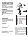
43000 SERIES
RANGE HOOD
READ AND SAVE THESE INSTRUCTIONS
!
INTENDED FOR DOMESTIC COOKING ONLY
WARNING
TO REDUCE THE RISK OF FIRE, ELECTRIC SHOCK, OR INJURY
TO PERSONS, OBSERVE THE FOLLOWING:
1. Usethisunitonlyinthemannerintendedbythemanufacturer.If
youhavequestions,contactthemanufacturerattheaddressor
telephonenumberlistedinthewarranty.
2. Beforeservicingorcleaningunit,switchpoweroffatservicepanel
andlockservicepaneltopreventpowerfrombeingswitchedon
accidentally.Whentheservicedisconnectingmeanscannot be
locked, securely fasten a prominent warning device, such as a
tag,totheservicepanel.
3. Installationworkandelectricalwiringmustbedonebyaqualified
person(s)inaccordancewithallapplicablecodesandstandards.
4. Sufficientairisneededforpropercombustionandexhaustingof
gases through the flue (chimney) of fuel burning equipment to
preventbackdrafting.Followtheheatingequipmentmanufacturer’s
guidelineandsafetystandardssuchasthosepublishedbythe
National Fire ProtectionAssociation (NFPA), and theAmerican
SocietyforHeating,RefrigerationandAirConditioningEngineers
(ASHRAE),andthelocalcodeauthorities.
5. Whencuttingordrillingintowallorceiling,donotdamageelectrical
wiringandotherhiddenutilities.
6. Ductedfansmustalwaysbeventedtotheoutdoors.
7. Donotusethisunitwithanysolid-statespeedcontroldevice.
8. Toreducetheriskoffire,useonlymetalductwork.
9. Usewithapprovedcord-connectionkitonly.
10.Thisunitmustbegrounded.
TO REDUCE THE RISK OF A RANGE TOP GREASE FIRE:
1. Neverleavesurfaceunitsunattendedathighsettings.Boilovers
causesmokingandgreasyspilloversthatmayignite.Heatoils
slowlyonlowormediumsettings.
2. AlwaysturnhoodONwhencookingathighheatorwhencooking
flamingfoods.
3. Cleanventilatingfansfrequently.Greaseshouldnotbeallowed
toaccumulateonfanorfilter.
4. Useproperpansize.Alwaysusecookwareappropriateforthe
sizeofthesurfaceelement.
TO REDUCE THE RISK OF INJURY TO PERSONS IN THE EVENT
OF A RANGE TOP GREASE FIRE, OBSERVE THE FOLLOWING:*
1. SMOTHERFLAMESwithaclose-fittinglid,cookiesheet,ormetal
tray,thenturnofftheburner.BECAREFULTOPREVENTBURNS.
Iftheflamesdonotgooutimmediately,EVACUATEANDCALL
THEFIREDEPARTMENT.
2. NEVERPICKUPAFLAMINGPAN-Youmaybeburned.
3. DONOTUSEWATER,includingwetdishclothsortowels-aviolent
steamexplosionwillresult.
4. UseanextinguisherONLYif:
A.You know you have a ClassABC extinguisher and you already
knowhowtooperateit.
B.Thefireissmallandcontainedintheareawhereitstarted.
C.Thefiredepartmentisbeingcalled.
D.Youcanfightthefirewithyourbacktoanexit.
*Basedon“KitchenFiresafetyTips”publishedbyNFPA.
!
CAUTION
1. Forindooruseonly.
2. Forgeneralventilatinguseonly.Donotusetoexhausthazardous
orexplosivematerialsandvapors.
3. To avoid motor bearing damage and noisy and/or unbalanced
impellers,keepdrywallspray,constructiondust,etc.offpowerunit.
4. Forbestcaptureofcookingimpurities,yourrangehoodshould
bemounted18-25”abovethecookingsurface.
5. Pleasereadspecificationlabelonproductforfurtherinformation
andrequirements.
IMPORTANT: OBSERVE ALL GOVERNING CODES AND ORDINANCES
Yourrangehoodhasbeendesignedtofilteroutsmoke,odors,and
grease which rise from the cooking surface. Before you being the
installationbesurethatallpartsandaccessoriesareremovedfrom
carton.Forbestresultsandeaseintheinstallationofthisrangehood,
readtheinstructionssheettobecomefamiliarwiththestep-by-step
installation.
TOOLS AND MATERIALS
REQUIRED
qDrill,electricorratchetdrive
q1/8"drillbitfordrillingpilotholes
q 1-1/4"woodbitfordrillingelectricalwiringaccesshole
q One common head screwdriver for securing hood mounting
screwstothecabinetandhoodsheetmetalparts
q Pliersforopeningknockouts
q Pencil,ruleandlevelformarkingcabinetlocations
q Sabersaworkeyholesawforcuttingthewallorcabinetopenings
q Metalsnips,ducttape,duct(withelbowsandtransition,ifnecessary),roofcementorcaulk,androoforwallcap,asrequired
q Electricalwiringandsuppliesoftypetocomplywithlocalcodes
Thefollowingmaterialsarerequiredonlyforinstallationonrecessed
bottomkitchencabinets:
q Two 1" x 2" x 12" (approximate length) wood strips (purchase
locally)
q Four1-1/4"longflatheadwoodscrews(purchaselocally)
INSTALLER:
LEAVETHISMANUALWITHTHEHOMEOWNER.
HOMEOWNER:
USEANDCAREINSTRUCTIONSONPAGE4.
Registeryourproductonlineat:www.broan.com/register
PREPARING THE HOOD
1.
ROOFCAP
ROOFCAP
Unpackhoodandcheckcontents.Youshouldreceive:
1–Filterwithbuilt-inlightlens
1–3-1/4"x10"damper/ductconnector
1–Installationpartsbag
BP87DAMPER(NOTINCLUDED) LOCATED AT
LEAST 6" FROM HOOD
INVERTICAL SECTION
OFDUCT
DAMPER
(INCLUDED)
LIGHT LENS
ALUMINUM OR
COMBINATION
FILTER
REMOVETHE
HOODDAMPER
FLAPIFITINTERFERESWITH
THEWALLCAP
DAMPER
JUNCTION BOX
2. Removejunctionboxcover.
3. Removetoporrearelectricalknockout.
4. Selectoneofthethreetypesofventingavailable:
Non-Vented—Removeventcoverfromhoodfront.Replace
thealuminumfilterwithanon-ductedfilter(BP57orR610050
-purchaseseparately).Goto"PreparingtheInstallationLocation".
Ducting directly through the wall (for range hoods mounted
onanexteriorwall).Shownaretwowaystoductthroughan
outsidewall.Ifawallcapisuseddirectlyoffthebackofthe
hood,specialcaremustbetakentomakesurethatthedamper
inthedamper/ductconnectoronthehoodanddamperinthe
wall cap do not interfere with each other when the hood is
operating.Thiscouldresultineitherinadequateairdelivery
orbackdrafts.Ifthisconditiondoesexist,removethehood
damperflap.Sometimeswhenusingawallcap,itiseasierto
ductverticallyandthenuseanelbow.
Ductingstraightupthroughroofusing3-1/4"x10"or7"round
duct.Forsinglestoryinstallations.
Ductingbetweenceilingjoistsformulti-storyinstallationsor
throughsoffitsabovecabinetswheresoffitconnectstooutside
walls.
VENT COVER
②
①
③
PREPARING THE
INSTALLATION LOCATION
Rectangular Vented—3-1/4"x10"verticalorhorizontal.Removeknockout#②forverticalorknockout#③forhorizontal
venting. Install damper/duct connector over opening. Go to
"PlanningDuctworkInstallation".
NOTE: MOUNT HOOD SO THAT BOTTOM OF HOOD IS 18"
TO 25" ABOVE COOKING SURFACE. TOP FRONT OF HOOD
SHOULD BE FLUSH WITH FRONT OF CABINET FRAME.
IF DISTANCE BETWEEN WALL AND FRONT OF CABINET
FRAME IS MORE THAN 12", THERE WILL BE A SPACE BETWEEN BACK OF HOOD AND WALL. THIS IS NORMAL.
OMIT STEP 1 IF HOOD WILL BE INSTALLED UNDER CABINETS WITH FLUSH BOTTOM.
FILLERSTRIP
Round Vented—7"vertical.Removeknockouts#①and#②
exposingductcollar.Goto"PlanningDuctworkInstallation".
PLANNING DUCTWORK
INSTALLATION
This section for vented hoods only. Non-vented hoods skip
this section and go on to "Preparing the Installation Location".
Beginplanningductworkbydecidingwhereductwillrunbetween
hoodandoutside.Forbestperformance,useshortestpossible
ductrunandaminimumnumberofelbows.Thereareseveral
choices.
1. Forcabinetswithrecessedbottomsonly:Installwoodfiller
stripsoneachsideofrecessedareaundercabinet.Usetwo
1" x 2" strips cut to length (use thicker strips if necessary).
Fastenstripswithwoodscrewsabout3"infromeachend.
2. Measureandmarkthefollowing:
a.) Electricalwiringopeninginwallorcabinet.
b.) Ductopeninginwallorcabinet(ventedhoodsonly).
2
CABINETCUTOUTS
1. Followappropriatedirectionsbelowfortypeofductworkyou
areinstalling.
3-1/4" x 10"
RECTANGULAR
VENTING
4"(10.2cm)
WallCap Discharge:Usesabersaworkeyholesawtocuthole
slightlylargerthanductsizeusedsothatductwilllineupeasily
withdamper/ductconnectoronhood.Installcasingstripsifcap
willbeinstalledonsiding.Attachrequiredamountofducttowall
capandrunductbacktohood.Fastencaptowallandcaulkwell.
Makesurethatenoughductrunsintotheroomsothattheduct
willoverlapthedamper/ductconnectorwhenthehoodisinstalled.
5¼"
1½"(3.8cm)
5¼"(13.3cm)
CABINET
CUTOUTS
STARTERHOLES
7" ROUND
VENTING
STARTERHOLES
5"
(12.7cm)
WARNING: WHEN CUTTING OR DRILLING INTO WALL OR
CABINET, BE CAREFUL NOT TO CUT EXISTING ELECTRICAL WIRING.
3. Drill1-1/4"electricalwiringopeninginwallorcabinetbottom.
4. Drillfourpilotholesincornersofmarkedductopeningandcut
openingwithsaberorkeyholesaw(ventedhoodsonly).
5. Holdhoodupagainstcabinetbottomandtracekeyholeslots
ontocabinetbottomorfillerstrips.
RoofCapDischarge:Cutaholeinroofslightlylargerthanduct
size being used.Trim shingles around hole so that they will fit
snuglyaroundhoodofcapwhencapisinstalled.Assemblethe
ductworkandtapealljoints.Runductworkdowntohoodlocation.
Makesurethatenoughductrunsintotheroomsothattheduct
willoverlapdamper/ductconnectorwhenhoodisputintoplace.
Leave3/4"ofductprojectingaboveroofsurfaceonhighside.
Trimductparalleltoroofpitchandsealallaroundductwithroof
cement.
Carefullytrimshinglesandslidebackofroofsheetundershingles.
Nailroofsheettoroofundershinglesattoptwocornersandtwo
sides.Nailsheetdirectlytoroofinfourplacesatbottom.
Usingroofcement,sealallnailheadsandshingleswhichwere
cutorlifted.Donotsealbottomedgeofroofsheet.
KEYHOLESLOTOUTLINE
FILLER
STRIPS
INSTALLING RANGE HOOD
WARNING: TURN OFF THE PROPER CIRCUIT AT THE SERVICE ENTRANCE BEFORE WIRING THIS RANGE HOOD.
1. Checkbaffleforcorrectventing.(Non-ventedoroutsidevented)
6. Screwthefoursuppliedscrewsformountingthehoodintothe
exactcenterofthenarrowendofthekeyholeslotsmarked
underneaththecabinet.Allow3/8"ofthescrewstoproject,
sothehoodcanbefittedintoplace.
CONNECTOR
INSTALLING THE DUCTWORK
KEYHOLESLOTS
THESE INSTRUCTIONS ARE FOR VENTED HOODS ONLY.
NON-VENTED HOODS SKIP THIS SECTION AND GO ON TO
"INSTALLING THE RANGE HOOD".
START AT THE EXTERIOR AND RUN DUCTWORK BACK TO
THE RANGE HOOD.
KNOCKOUT
OPENING
FOR BEST PERFORMANCE OF YOUR RANGE HOOD, USE
THE SHORTEST POSSIBLE DUCT RUN AND A MINIMUM
NUMBER OF ELBOWS.
2. Runelectricwiringthroughholedrilledinwallorcabinet.Split
wiringfor6"andinstallproperconnectorfortypeofwireused.
3. Positionhoodsothat:
a.) Wiringisroutedthroughknockoutopening.
b.) Largepartofkeyholeslotsfitoverhoodmountingscrews.
c.) Damper/ductconnectorslidesintoductwork(3-1/4"x10"
ventedhoodsonly)
4. Adjusthoodsothathoodfrontisflushwithcabinetframe.
5. Tightenhoodmountingscrewsfirmly.
NEVER VENT A RANGE HOOD INTO AN ATTIC SPACE
BECAUSE A BUILDUP OF GREASE WILL BECOME A FIRE
HAZARD.
USE ONLY METAL DUCTWORK (DO NOT USE PLASTIC
DUCT). ASSEMBLE SECURELY SO THAT IN CASE OF A
GREASE FIRE ON THE RANGE, THE FIRE WILL BE CONTAINED INSIDE METAL DUCTWORK.
IT IS A GOOD PRACTICE TO TAPE ALL DUCT CONNECTIONS,
MAKING THEM BOTH SECURE AND AIR TIGHT.
3
WARNING: ALL ELECTRICAL CONNECTIONS MUST BE
MADE IN ACCORDANCE WITH LOCAL CODES, ORDINANCES, OR NATIONAL ELECTRICAL CODE. IF YOU ARE
UNFAMILIAR WITH METHODS OF INSTALLING ELECTRICAL WIRING, SECURE THE SERVICES OF A QUALIFIED
ELECTRICIAN.
6. Completeelectricalwiringinjunctionboxfollowingrequired
codesandreplacejunctionbox.Makesurethatallwiringis
safelycontainedinside.
7. Installlightbulb(75Wattmaximum).
8. Ifthehoodisvented,removecharcoalpadfromfilter.Install
filter.
9. Turnonpowerandcheckoperationoffanandlight.Makesure
thatdamperoperatesfreely.
REPLACEMENT PARTS
7
2
6
1
5
USE AND CARE
ALUMINUM FILTER
Forgreatestefficiency,thepermanent-typealuminumfiltershould
beremovedandcleanedperiodically.Toclean,thefiltershould
besoakedinhotwateranddetergentandthoroughlyrinsed.The
aluminumfiltercanbecleanedinadishwasher.
3
COMBINATION FILTER
Thisfiltershouldbeinspectedperiodicallyandwhenitbecomes
saturated,itshouldbereplaced.Therearenoeffectivemeansof
reactivatingthisfilter.
LIGHTS
Donotusebulblargerthan75Wattsinlightsocket.
CARE OF EXTERIOR SURFACES
Cleanyourhoodwithamilddetergentsuitableforpaintedsurfaces.DONOTUSEABRASIVECLOTH,STEELWOOLPADS
ORSCOURINGPOWDERS.
WARNING: ALWAYS DISCONNECT ELECTRIC POWER BEFORE SERVICING RANGE HOOD.
CARE OF FAN MOTOR
Fan motor has lifetime sealed bearings that never need oiling
under normal usage.A few drops on each bearing after three
yearsofheavyusagewillprolongthemotorlife.Cleanmotorwith
adampclothandgrease-cuttingdetergentwhenaheavycoating
ofgreasehasaccumulated.
HOW TO AVOID A COMMON RANGE-TOP GREASE FIRE
Yourrangehoodprovidesaprotectivebarrierbetweenthecooking
surfaceandthecabinets.
Keepfan,filters,andgrease-ladensurfacesCLEANaccordingto
theinstructions.
Always turn hood ON when cooking at high heat to keep the
cookingareaandthehoodcooler.
Usehighheatsettingsonlywhennecessary.
Neverleavecookingsurfaceunattended.Boil-overcausessmokingandgreasyspilloversthatmayignite.
Alwaysuseadequate-sizedutensils.
Ifpreparingflamingfoods,suchasCherriesJubilee,alwaysturn
hoodONtoHIGHtopreventahighheatsituationwhichcancause
damageorfire.
HOWTO EXTINGUISH A COMMON RANGE-TOP GREASE FIRE
Neverpickupaflamingpan.Ifdroppedflamescanspreadquickly.
DONOTUSEWATER!Aviolentsteamexplosionmayresult.Wet
dishclothsortowelsarealsodangerous.
Smotherflameswithaclose-fittinglid,cookiesheetormetaltray.
Flaminggreasecanalsobeextinguishedwithbakingsodaora
multi-purposedrychemicalextinguisher.
Turnoffsurfaceunits–ifyoucandosowithoutgettingburned.
Replacement parts
can be ordered on our
website at
www.Broan.com
4
KeyNo. PartNo.
Description
1
97016971 Fan Switch – White (Includes Light Switch)
97016972 Fan Switch – Almond (Includes Light Switch)
97016970 Fan Switch – Black (Includes Light Switch)
97016973 Fan Switch – Biscuit (Includes Light Switch)
2
97016971 Light Switch – White (Includes Fan Switch)
97016972 Light Switch – Almond (Includes Fan Switch)
97016970 Light Switch – Black (Includes Fan Switch)
97016973 Light Switch – Biscuit (Includes Fan Switch)
3
R730088
Motor/Blade Assembly
4
R610045 Filter - Aluminum (use with ducted hoods only)
*
R610050
Filter – Ductless
*
R610051
Filter Pads – Ductless
5
R566088
Lampholder
6
99091020 Vent Cover - White
99091021 Vent Cover - Almond
99091022 Vent Cover - Black
99091027 Vent Cover - Biscuit
7
R6689601 Wiring Cover - White
R6689602 Wiring Cover - Almond
R6689604 Wiring Cover - Black
R6689605 Wiring Cover - Biscuit
* Not shown. Purchase separately.
WARRANTY
BROAN-NUTONE ONE YEAR LIMITED WARRANTY
Broan-NuTone warrants to the original consumer purchaser of its products that such products will be free from defects in
materials or workmanship for a period of one year from the date of original purchase. THERE ARE NO OTHER WARRANTIES,
EXPRESS OR IMPLIED, INCLUDING, BUT NOT LIMITED TO, IMPLIED WARRANTIES OF MERCHANTABILITY OR FITNESS
FOR A PARTICULAR PURPOSE.
During this one-year period, Broan-NuTone will, at its option, repair or replace, without charge, any product or part which is
found to be defective under normal use and service.
THIS WARRANTY DOES NOT EXTEND TO FLUORESCENT LAMP STARTERS, TUBES, HALOGEN AND INCANDESCENT
BULBS, FUSES, FILTERS, DUCTS, ROOF CAPS, WALL CAPS AND OTHER ACCESSORIES FOR DUCTING. This warranty does
not cover (a) normal maintenance and service or (b) any products or parts which have been subject to misuse, negligence,
accident, improper maintenance or repair (other than by Broan-NuTone), faulty installation or installation contrary to
recommended installation instructions.
The duration of any implied warranty is limited to the one-year period as specified for the express warranty. Some states do not
allow limitation on how long an implied warranty lasts, so the above limitation may not apply to you.
BROAN-NUTONE’S OBLIGATION TO REPAIR OR REPLACE, AT BROAN-NUTONE’S OPTION, SHALL BE THE PURCHASER’S
SOLE AND EXCLUSIVE REMEDY UNDER THIS WARRANTY. BROAN-NUTONE SHALL NOT BE LIABLE FOR INCIDENTAL,
CONSEQUENTIAL OR SPECIAL DAMAGES ARISING OUT OF OR IN CONNECTION WITH PRODUCT USE OR PERFORMANCE.
Some states do not allow the exclusion or limitation of incidental or consequential damages, so the above limitation or
exclusion may not apply to you.
This warranty gives you specific legal rights, and you may also have other rights, which vary from state to state. This warranty
supersedes all prior warranties.
To qualify for warranty service, you must (a) notify Broan-NuTone at the address or telephone number below, (b) give the model
number and part identification and (c) describe the nature of any defect in the product or part. At the time of requesting warranty
service, you must present evidence of the original purchase date.
Broan-NuTone LLC, 926 W. State Street, Hartford, Wisconsin 53027 www.broan.com 800-558-1711
626850
99043005H
SERIE 43000
CAMPANA DE EXTRACTORA
LEA Y CONSERVE ESTAS INSTRUCCIONES
!
PREVISTO PARA COCINAR DOMÉSTICO SOLAMENTE.
!
ADVERTENCIA
PRECAUCION
PARA REDUCIR EL RIESGO DE INCENDIO, CHOQUE ELECTRICO, O
LESION A PERSONAS, PROCURE LO SIGUIENTE:
1. Utiliceestaunidadsóloenlamaneraprescritaporelfabricante.Sitiene
ustedalgunapregunta,comuníqueseconelfabricantealadireccióno
elteléfonoindicadosenlagarantía.
2. Antesdeefectuaralgúnservicioolimpieza,sedebedesconectarla
corriente eléctrica en el armario de circuitos y asegurarlo con llave
paraevitarquelacorrienteseaconectadaaccidentalmente.Cuandoel
dispositivoparadesconectarelservicioeléctriconopuedesercerrado
conalgúntipodetraba,sujetefuertementealpaneldeservicio,una
etiquetadeadvertenciaprominente.
3. Todotrabajodeinstalaciónycableadoeléctricodebeserrealizadopor
personalcalificadoydeacuerdocontodosloscódigosynormaspertinentes,incluyendoloscódigosynormasrelacionadosconconstrucción
clasificadaparaincendio.
4. Airesuficienteesnecesarioparafacilitarlacombustiónadecuadayla
salidaapropiadadegasesporlachimeneadelaunidadyparaevitar
corrientesdeaireinvertidas.Sigalasinstruccionesymedidasdeseguridaddelfabricantedelequipoydelassociedadesprofesionalesde
equiposdecalentadoresylosreglamentosdeseguridadlocales.
5. Acortaroperforarlaparedoeltecho,nodañeelcableadoeléctricou
otrosserviciospúblicosocultosalavista.
6. Los abanicos con ducto deberán siempre tener una salida hacia el
exterior.
7. Noutiliceestaunidadenconjuntoconcualquierdispositivodecontrol
develocidaddeestadosólido.
8. Parareducirelriesgodeincendio,usesóloductosdemetal.
9. Usoconelkitaprobadodellaconexióndelacuerdasolamente.
10.Estaunidadsedebeinstalarcontierraefectiva.
PARAREDUCIRELRIESGODEINCENDIODEBIDOAGRASAACUMULADAENLASHORNILLAS:
1. Nunca deje sin atender las unidades de superficie cuando tengan
ajustesaltos.Losrebosespuedenprovocarhumoyderramesgrasosos
quesepuedenincendiar.Calientelentamenteelaceiteenunajuste
bajoomedio.
2. SiempreENCIENDAlacampanacuandococineconaltatemperatura
ocuandococinealimentosquesepuedanincendiar.
3. Limpieconfrecuencialosventiladores.Nodebepermitirquelagrasa
seacumuleenelventiladornienelfiltro.
4. Utilice un sartén de tamaño adecuado. Siempre utilice el utensilio
adecuadoaltamañodelelementodesuperficie.
PARAREDUCIRELRIESGODELESIONAPERSONASRESULTADODE
UNINCENDIODEBIDOAGRASAACUMULADAENLASHORNILLAS,
PROCURELOSIGUIENTE:*
1. AHOGUE LAS LLAMAS con una tapa ajustada o charola de metal,
después apague la hornilla.TENGA CUIDADOA FIN DE EVITAR
QUEMADURAS.Silasllamasnoseapagandeinmediato,EVACUEY
AVISEALOSBOMBEROS.
2. NOLEVANTENUNCAUNASARTENQUEESTEENLLAMAS-Usted
sepodráquemar.
3. NO UTILICEAGUA, incluyendo toallas de cocina mojadas - puede
resultarunaexplosióndevaporviolenta.
4. UtiliceunextinguidorSOLAMENTEsi:
A. UstedsabequetieneunextinguidordeclaseABCylosabeutilizar.
B. Elincendioespequeñoycontenidodentrodeláreadondeseinició.
C. Losbomberoshansidoavisados.
D. Ustedpuedecombatirelincendioconunasalidaasuespalda.
* Basadoenlasrecomendacionespara“SeguridadenlaCocina”publicadas
porlaNFPAdelosEEUU.
1. Paraelusodeinteriorsolamente.
2. Solamenteparausogeneraldeventilación.Noutiliceparadescargar
materialesovaporesriesgososoexplosivos.
3. Paraevitardañosalmotoryevitarquelasnavajasdelabanicoemitan
mucho ruido o estén fuera de balance, mantenga el motor libre de
pelusa,polvo,etc.
4. Paraobtenermejoresresultadosenlacapturadelosvaporesdela
estufa,elextractordebemontarseaentre18"y25"(45.7y63.5cm)
sobrelashornillasdelaestufa.
5. Porfavorlealaetiquetaconlasespecificacionesdelequipoparaotros
requisitosymayorinformación.
IMPORTANTE: OBSERVE TODOS LOS CODIGOS Y REGULACIONES VIGENTES.
Sucampanadecocinahasidodiseñadaparasacarelhumo,losolores,
ylagrasaquesalendelasuperficiedondesecocina.Antesdecomenzar la instalación asegúrese que ha sacado del cartón todas la piezas
yaditamentos.Paraobtenermejoresresultadosyfacilitarlainstalacion
delacampana,lealahojadoinstuccionesafindefamiliarizarseconla
instalacionpasoapaso.
HERRAMIENTAS Y MATERIALES QUE SE
NECESITAN
q Taladro,eléctricooaccionadoportrinquete
q Brocade1/8"(3.175mm)parataladraragujerospilotos
q Brocaparamaderade1¼"(31.75mm)parataladrarelorificiodeacceso
q Un destornillador de cabeza común para asugurar los tornillos de
montajedelacampanaalmuebleylaspiezasdechapametalica
q Alicatesparasacarlosdiscosremovibles
q Lápiz,reglaynivelparamarcarelmueble
q Sierra sable o de calar para cortar la pared o hacer agujeros en el
mueble
q Tijerasdehojalatero,cintaparaducto,ducto(concodosytransicionessi
lasnecesita),cenentoparatechosomasillaytapatechosotapapared,
segúnseanecesario
q Alambreymaterialeseléctricosdeltiporequeridoporloscódigoslocales
Losmaterialessiguientessenecesitansolamenteparalainstalaciónde
mueblesdecocinaempotradosenlaparteinferior
q Dos1"x2"x12"(25x50x305mm)tirasdemadera(largoaproximado)
(cómpreloslocalmente)
q Cuatrotornillosdecabezaplanaparamaderade1¼"(3.2mm)delargo
(cómpreloslocalmente)
INSTALADOR: DEJE ESTE MANUAL CON EL USUARIO.
USUARIO: INSTRUCCIONES PARA EL USO Y CUIDADO EN
LA PAGINA 8.
Registresuproductoenlíneaen:www.broan.com/register
PREPARACION DE LA CAMPANA
1. Desempaque la campana y verifique el contenido. Ud debe
recibir:
1–Filtroconcristalesdeluzempotrados
1–Conectorregistro/ductode3¼"x10"(83x25.4cm)
1–Bolsitaconpiezasparalainstalación
CRISTALES
DE LA LUZ
TAPATECHO
TAPATECHO
REDONDODE
7"(17.8cm)
REGISTRO BP87 (NO
SEINCLUYE)SITUADO
PARLOMENOS6"(15.2
CM) DE LA CAMPANA
EN ELTRAMOVERTICALDELDUCTO
MUEBLE
VERTICAL
TAPAPARED
REGISTRO
(INCLUIDO)
FILTRO DE
ALUMIINIO O
COMBINACIÓN
HORIZONTAL
TAPA DE LA CAJA DE
2. Quitelatapadelacajadeempalmes.
EMPALMES
3. Saqueeldiscoremovibledeltopeodelapartedeatrás.
4. Seleccioneunodelostrestiposdeventilaciónqueseofrecen:
Sin Ventilación-Saquelacubiertadeventeada.Reemplazeel
filtrodealuminioconfiltrosinducto(BP57oR610050compre
porseparado).Pasealasección"ComoPropararelSitiodela
Instalación".
②
①
" )
1½8cm
(3,
③
(197½"
,1c
30" m)
36" (76,2
(9 cm
1,4 )
cm
)
CUBIERTA DE
VENTEADA
3/8"
(1cm)
¾"
(1,9cm)
" )
1½8cm
)
(3,
(2, 1"
12",5cm
5c
m)
(30 9" 9cm)
,
2
6"
2
(
(15
)
"
2 cm
,2c
1
m)
(5,
"
17½cm)
5
,
4
(4
Ventilación Rectangular-Verticalóhorizontalde3¼"x10"
(8.3x25.4cm).Saqueeldisco#②sieslaventilaciónverticaloel#③sieshorizontal.Instaleelconectorpararegistro/
ductosobrelaabertura.Inviertaeldeflectordelaposiciónsin
ventilaciónhaciaafuera.Pasea"ComoPlanearlaInstalación
delDucto".
RECTANGULAR
DE3¼"X10"
(8.3X25.4cm)
VENTIACION DE DUCTO
REDONDO DE 7" (17.8 cm)
SAQUELACOMPANAALETA
DELREGISTRO
ESTORBAAL
REGISTRODEL
TAPAPARED
VENTIACION RECTANGULAR DE
3¼" X 10" (8.3 X 25.4 cm)
Elductodirectoatravésdelapared(paracampanasdecocina
montadasenunaparedexterior).Semuestrandosmaneras
deinstalarelductoatravésdeunaparedexterior.Siseusaun
tapapareddirectamentepordetrásdelacampana,debetenerse
muchocuidadoenqueelregistroenelconectorregistro/ducto
delacampanayelregistroeneltapaparednoseinterfieran
entresicuandofuncionalacampana.Estopodríaresultaren
inadecuado movimiento de aire o contratiros. Cuando exista
estacondiciónquitelaaletadelregistrodelacampana.Algunas
vecescuandoseusauntapaparedesmásfácilcorrerelducto
verticalmenteyluegousaruncodo.
Ductoderechoatravésdeltechousandoductoredondode3¼"
x10"(8.3x25.4cm)óde7"(17.8cm).Parainstalacionesde
unsolopiso.
Ductosentrelosmontantesdeltechoeninstalacionesdevarios
pisosoatravésdecielosrasossobremueblesdondeelcielo
rasoestáconectadoalasparedesexteriores.
PREPARACION DEL SITIO DE LA INSTALACION
NOTA: MONTE LA CAMPANA PARA QUE SU PARTE INFERIOR QUEDE DE 18" (45.7 cm) A 25" (63.5 cm) SOBRE LA
SUPERFICIE DONDE SE COCINA. EL TOPE FRONTAL DE LA
CAMPANA DEBE ESTAR A RAS CON EL MARCO DELANTERO
DE MUEBLE.
SI LA DISTANCIA ENTRE LA PARED Y EL FRENTE DEL
MARCO DEL MUEBLE ES MAS DE 12" (30.5 cm) QUEDARA
UN ESPACIO ENTRE LA PARTE TRASERA DE LA CAMPANA
Y LA PARED. ESTO ES NORMAL.
OMITASE EL PASO 1 SI SE VA A INSTALAR DEBAJO DE
MUEBLES CON FONDO AL RAS.
3"(7.6cm)
Ventilación Redonda -Vertical de 7" (17.8 cm). Saque los
discos#①y#②paraexponerelcollardeducto.Pasea"Como
PlanearlaInstalacióndelDucto".
COMO PLANEAR LA INSTALACION DEL DUCTO
Esta sección es solamente para companas venteadas. Para
las companas sin ventilación omitase esta sección y pase a
"Como Preparar el Sitio de la Instalación".
Empiecelosplanesparaelductodecidiendopordondevaacorrer
elductoentrelacampanayelexterior.Paremejoresresultados
uselavíamáscortaposibleyelmenornúmerodecodos.Hay
variasposibilidades.
6
TIRADERELLENO
3"
(7.6
cm)
1. Solamenteparamueblesconfondosempotrados:Instaletiras
derellenodemaderaacadaladodeláreaempotradadebajo
delmueble.Usedos1"x2"(2.54x5.08cm)tirascortadasa
lolargo(usetirasmásgruesassiesnecesario).Asegurelas
tirascontornillosparamaderacomo3"(7.62cm)desdecada
extremo.
NUNCA VENTEE UNA CAMPANA DE COCINA EN EL ATICO O
DESVAN PORQUE LA ACUMULACION DE GRASA CREARA EL
PELIGRO DE INCENDIO.
EMPLEE UNICAMENTE DUCTOS DE ACERO (NO DE PLASTICO).
ASEGUE BIEN EL ENSAMBLAJE PARA QUE EN CASO DE PRODUCIRSE INCENDIO DEBIDO A LA GRASA, EL FUEGO QUEDARA
CONTENIDO DENTRO DEL DUCTO ACERO.
ES UNA BUENA PRACTICA CUBRIR TODAS LA CONEXIONES DE
DUCTO CON CINTA PARA HACERLAS SEGURAS Y HERMETICAS.
MUESCASENELMUEBLE
VENTIACION
RECTANGULAR
DE 3¼" x 10"
(8.26 x 25.4 cm)
4"(10.2cm)
1. Sigalasdireccionesapropiadasquesedanabajoparaeltipodeducto
quevaainstalar.
5¼"
1½"(3.8cm)
5¼"(13.3cm)
AGUJEROSPARACOMENZAR
MUESCASEN
ELMUEBLE
DescargaporlaTapapared:Useunasierradesableodecalarparacortar
unagujeroligeramentemásgrandequeeltamañodelductoempleadoa
findequeelductoquedebienalineadoconelconectorderegistro/ducto
delacampana.Instaletirascontramarcosilatapavaainstalarseenlas
tablasdelapared.Conectelalongitudrequeridadeductoalatapapared
ycorraelductohacialacampana.Asegurelatapaalaparedycalafatee
bien.Asegúresequesuficienteductoentraenelcuartoparaquerecubra
elconectordelregistro/ductocuandoseinstalelacampana.
VENTILACION
REDONDO DE
7" (17.8 cm)
AGUJEROSPARA
COMENZAR
5"
(12.7cm)
2. Midaymarquelosiguiente:
a.) La abertura para el alambrado eléctrico en la pared o
mueble.
b.) Aberturaparaelductoenlaparedomueble(campanas
conventilaciónsolamente).
ADVERTENCIA: CUANDO CORTE O TALADRE LA PARED O EL
MUEBLE TENGA CUIDADO DE NO CORTAR LOS ALAMBRES
ELECTRICOS INSTALADOS.
3. Taladreelagujeroparaelalambradoeléctricoenlaparedoel
fondodelmueble.
4. Taladrecuatroagujerospilotosenlasesquinasdeagujerodel
ductomarcadoyhagaelcorteconunasierrasableodecalar
(campanasconventilaciónsolamente).
5. Sostengalacampanacontraelfondodelmuebleytracelas
aberturasdeojoenelfondodelmuebleoenlastirasderelleno.
¾"
(1.9cm)
DescargaporlaTapatecho:Corteunagujeroeneltecholigeramentemás
grandequeeltamañodelductoempleado.Recortelastejasalrededor
delagujeroparaqueencajenperfectamentealrededordelatapacuando
selainstale.Armelosductosycubraconcintatodaslasjuntas.Corrael
ductohaciaabajoalsitiodondeestálacampana.Asegúresequesuficiente
ductoentraenelcuartoparaquerecubraelconectordelregistro/ducto
cuandoseinstalelacampanaensulugar.Hagaque¾"(1.9cm)deducto
sobresalgaporarribadelasuperficiedeltechoenelladoalto.
Recorteelductoparalelamentealainclinacióndeltechoysellebien
alrededordelductoconcementoparatechos.
Concuidadorecortelastejasydeslicelahojadetechopordebajodelas
tejaseneltopededosesquinasydoslados.Clavelahojadirectamente
altechoencuatrolugaresenlaparteinferior.
Empleecementoparatechosyselletodaslascabezasdeclavosylas
tejasrecortadasolevantadas.Noselleelbordeinferiordelahojadetecho.
CONTORNODELAS
ABERTURASDEOJO
TIRASDE
RELLENO
INSTALACION DE LA CAMPANA DE COCINA
ADVERTENCIA: DESCONECTE EL CIRCUITO CORRESPONDIENTE
EN LA ENTRADA DEL SERVICIO ELECTRICO ANTED DE ALAMBRAR ESTA CAMPANA DE COCINA.
1. Veaqueeldeflectorestáventeadocorrectamente(sinventilaciónode
venteoalexterior.
6. Atornille los cuatro tornillos que se proveen para montar la
campanaenelcentromismodelextremoestrechodelasaberturasdeojomarcadasdebajodelmueble.Dejequelostornillos
sobresalgan3/8"(10mm)paraquelacampanapuedaencajar
bienensulugar.
CONECTOR
ABERTURADEOJO
INSTALACION DE LOS DUCTOS
ESTAS INSTRUCCIONES SON SOLAMENTE PARA CAMPANAS CON
VENTILACION. PARA CAMPANAS SIN VENTILACION OMITA ESTA
SECCIONY VAYA A "INSTALACION DE LA CAMPANA DE COCINA".
COMIENCE AFUERA E INSTALE EL DUCTO HACIA LA CAMPANA.
PARA OBTENER EL MEJOR RENDIMIENTO DE LA CAMPANA EMPLEE EL DUCTO MAS CORTO POSIBLE Y UN NUMERO MINIMO
DE CODOS.
7
ABERTURADELAGUJEROCIEGO
2. Corraelcableeléctricoporelagujerotaladradoenlaparedoelmueble.
Separelosalambrespara6"(15.2cm)einstaleelconectorapropiado
altipodealambrequeemplea.
3. Coloquelacampanadetalmaneraque:
a.) Losalambrespasenporlaaberturadelagujerociego.
b.) Lamayorpartedelasaberturasdeojocabensobrelostornillos
demontajedelacampana.
c.) Elconectorderegistro/ductosedeslizadentrodelducto(campanas
conventilaciónde3¼"x10"(8.25x25.4cm)solamente).
4. Coloquelacampanaparaquesufrentequedearasconelmarcodel
mueble.
5. Aprietebienlostornillosdemontajedelacampana.
ADVERTENCIA: TODAS LAS CONEXIONES ELECTRICAS
DEBEN HACERSE EN CONFORMIDAD CON LOS CODIGOS Y
REGULACIONES LOCALES O EL CODIGO ELECTRICO NACIONAL. SI UD. NO ESTA FAMILIARIZADO CON LOS METODOS
DE INSTALACION DEL ALAMBRADO ELECTRICO, CONTRATE
LOS SERVICIONS DE UN ELECTRISTA CALIFICADO.
6. Complete el alambrado eléctrico en la caja de derivaciones
de acuerdo con los códigos vigentes y reemplace la caja.
Asegúresequetodoslosalambresestándentrodelacaja.
7. Instaleunfoco(75vatiosmáximo).
8. Silacampanallevaventilación,quiteeltacodecarbóndelfiltro.
Instaleelfiltro.
9. Conectelaelectricidadyobserveelfuncionamientodelventiladorylaluz.Asegúresequeelregistrofuncionalibremente.
LISTA DE REPUESTOS
7
2
6
1
5
3
4
USO Y CUIDADO
FILTRO DE ALUMINIO
Para mayor eficiencia el filtro de aluminio permanente deberá
sacarse y limpiarse periódicamente. Para limpiar el filtro debe
remojarseenaguacalientecondetergenteylavarsecompletamente.Elfiltrodealuminiopuedelavarseenlalavadoradeplatos.
FILTRO COMBINACION
Este filtro debe examinarse periódicamente y cuando llega a
saturarse debe reemplazarse. No hay una manera efectiva de
reactivarestefiltro.
LUCES
Noempleeunfocodemásde75vatiosenunportafocoliviano.
CUIDADO DE LAS SUPERFICIES EXTERIORS
Limpiesucampanautilizandoundetergentesuaverecomendado
parasuperficiespintadas.NOUSETELASABRASIVAS,TACOS
DELANADEACEROOPOLVOSPARAFREGAR.
ADVERTENCIA: SIEMPRE DESCONECTE LA ELECTRICIDAD
ANTE DE HACER SERVICIO EN LA CAMPANA DE COCINA.
CUIDADO DEL MOTOR DEL VENTILADOR
Elmotordelventiladorllevacojinetesselladospermanentesque
norequierenaceitebajousonormal.Unaspocasgotasencada
cojinetedespuésdetresañosdetrabajopesadoalagaránlavida
delmotor.Limpieelmotorconuntrapohúmedoydetergentequitagrasacuandoveaquesehaacumuladounadensacapadegrasa.
COMO EVITAR QUE OCURRA UN INCENDIO DEBIDO A LA GRASA QUE SE
ACUMULAENUNEXTRACTORCOMUN
• Su extractor proporciona una barrera protectora entre la superficie para
cocinar y los gabinetes.
• Mantenga el abanico, los filtros y las superficies donde se acumula la grasa
LIMPIAS conforme a las instrucciones.
• ENCIENDA siempre el extractor cuando esté cocinando a fuego alto para
mantener el area para cocinar y el extractor limpios.
• Utilice las hornillas de fuego alto solamente cuando sea necesario.
• No deje las hornillas de la estufa sin atención cuando esté cocinando.
El vapor o el aceite que salpique puede ocasionar un incendio o
acumulación de humo.
• Siempre utilice los utensilios del tamaño adecuado.
• Si está preparando alimentos flameados, como las Cerezas a la Jubilee, ENCIENDA siempre el extractor en ALTO para evitar que el calor pueda causar
algún daño o un incendio.
COMOEXTINGUIRUNINCENDIOENUNEXTRACTORCOMUN
•No levante nunca una sartén que esté en llamas. Si se le cae, las llamas se
pueden extender rapidamente.
• ¡NO UTILICE AGUA PARA APAGARLO! Puede ocasionar una explosión de
vapor. Las toallas de cocina mojadas también son peligrosas.
• Ahogue las llamas con una tapa ajustada o una charola.
• Las llamas provocadas por la grasa también se pueden apagar con bicarbonato
de sodio o un extinguidor químico.
• Apague las hornillas - si puede hacerlo sin quemarse.
Las piezas de repuestos
se pueden pedir en
nuestro website en
www.Broan.com
ClaveNo.
1
2
3
4
*
*
5
6
7
PiezaNo.
97016971
97016972
97016970
97016973
97016971
97016972
97016970
97016973
R730088
R610045
R610050
R610051
R566088
99091020
99091021
99091022
99091027
R6689601
R6689602
R6689604
R6689605
Descripción
Interruptor de Ventilador – Blanco (incluye interruptor de la luz)
Interruptor de Ventilador – Almendra (incluye interruptor de la luz)
Interruptor de Ventilador – Negro (incluye interruptor de la luz)
Interruptor de Ventilador – Beige (incluye interruptor de la luz)
Interruptor de la Luz – Blanco (incluye interruptor de ventilador)
Interruptor de la Luz – Almendra (incluye interruptor de ventilador)
Interruptor de la Luz – Negro (incluye interruptor de ventilador)
Interruptor de la Luz – Beige (incluye interruptor de ventilador)
Conjunto de Motor/Aspa
Filtro de Aluminio (uso con extractor ducto solamente)
Filtro - Sin Ducto
Tacos de Filtro – Sin Ducto
Portafoco
Cubierta de Venteada - Blanco
Cubierta de Venteada - Almendra
Cubierta de Venteada - Negro
Cubierta de Venteada - Beige
Cubierta para la Conexion Electrica - Blanco
Cubierta para la Conexion Electrica - Almendra
Cubierta para la Conexion Electrica - Negro
Cubierta para la Conexion Electrica - Beige
* No ilustrado. Compre por separado.
GARANTIA
GARANTIA BROAN-NUTONE LIMITADA POR UN AÑO
Broan-NuTone garantiza al consumidor comprador original de sus productos que dichos productos carecerán de defectos en
materiales o en mano de obra por un período de un año a partir de la fecha original de compra. NO EXISTEN OTRAS GARANTIAS,
EXPLICITAS O IMPLICITAS, INCLUYENDO, PERO NO LIMITADAS A, GARANTIAS IMPLICITAS DE COMERCIALIZACION O APTITUD
PARA UN PROPOSITO PARTICULAR.
Durante el período de un año, y a su propio criterio, Broan-NuTone reparará o reemplazará, sin costo alguno cualquier producto
o pieza que se encuentre defectuosa bajo condiciones normales de servicio y uso.
LA PRESENTE GARANTÍA NO CUBRE LOS TUBOS FLUORESCENTES NI SUS ARRANCADORES, BOMBILLAS DE HALÓGENO
E INCANDESCENTES, FUSIBLES, FILTROS, CONDUCTOS, TAPONES DE TECHO O PAREDES Y DEMÁS ACCESORIOS PARA
CONDUCTOS. Esta garantía no cubre (a) mantenimiento y servicio normales o (b) cualquier producto o piezas que hayan sido
utilizadas de forma errónea, negligente, que hayan causado un accidente, o que hayan sido reparadas o mantenidas inapropiadamente (por otras compañías que no sean Broan-NuTone), instalación defectuosa, o instalación contraria a las instrucciones
de instalación recomendadas.
La duración de cualquier garantía implícita se limita a un período de un año como se especifica en la garantía expresa. Algunos
estados no permiten limitaciones en cuanto al tiempo de expiración de una garantía implícita, por lo que la limitación antes
mencionada puede no aplicarse a usted.
LA OBLIGACION DE BROAN-NUTONE DE REPARAR O REEMPLAZAR, SIGUIENDO EL CRITERIO DE BROAN-NUTONE, DEBERA
SER EL UNICO Y EXCLUSIVO RECURSO LEGAL DEL COMPRADOR BAJO ESTA GARANTIA. BROAN-NUTONE NO SERA
RESPONSABLE POR DAÑOS INCIDENTALES, CONSIGUIENTES, O POR DAÑOS ESPECIALES QUE SURJAN A RAIZ DEL USO O
DESEMPEÑO DEL PRODUCTO. Algunos estados no permiten la exclusión o limitación de daños incidentales o consiguientes,
por lo que la limitación antes mencionada puede no aplicarse a usted.
Esta garantía le proporciona derechos legales específicos, y usted puede también tener otros derechos, los cuales varían de estado
a estado. Esta garantía reemplaza todas las garantías anteriores.
Para calificar en la garantía de servicio, usted debe (a) notificar a Broan-NuTone al domicilio o al número de teléfono que se menciona
abajo, (b) dar el número del modelo y la identificación de la pieza, y (c) describir la naturaleza de cualquier defecto en el producto o
pieza. En el momento de solicitar servicio cubierto por la garantía, usted debe de presentar evidencia de la fecha original de compra.
Broan-NuTone LLC, 926 W. State Street, Hartford, Wisconsin 53027 www.broan.com 800-558-1711
626850
99043005H


![HMBC[L]_Spanish_56571 [From English 54383].pub](http://vs1.manualzilla.com/store/data/006216602_1-cfe031224017a12fd1747226d4724f03-150x150.png)