1
Xerox DocuPrint EPS
Using LCDS Print Description Language
701P21091
Version 3.7
May 2003
Xerox Corporation
Global Knowledge and Language Services
West Coast Operations
701 South Aviation Boulevard, ESM1-058
El Segundo, CA 90245
©2003 by Xerox Corporation. All rights reserved.
Copyright protection claimed includes all forms and matters of copyrighted
material and information now allowed by statutory or judicial law or hereinafter
granted including without limitation, material generated from the software
programs that are displayed on the screen such as styles, templates, icons,
screen displays, looks, etc.
Printed in the U.S.A., U.K., and France.
XEROX, XEROX Europe, and XEROX Canada Limited, The Document
Company, the stylized X, and all names and identifying numbers used in
connection with Xerox products mentioned in this publication are trademarks
of XEROX CORPORATION. All non-Xerox brands and product names are
trademarks or registered trademarks of their respective companies. Other
company trademarks are also acknowledged.
While the information in this guide is correct at the time of this publication,
Xerox reserves the right at any time to change the information without notice.
Changes are made periodically to this document. Changes and technical
updates will be added in subsequent editions.
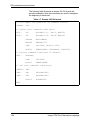
Table of contents
Laser safety . . . . . . . . . . . . . . . . . . . . . . . . . . . . . . . . . . . . . . . . . . xvii
Ozone information: U. S. only . . . . . . . . . . . . . . . . . . . . . . . . . . . . . . . . xvii
Operation safety: U. S. . . . . . . . . . . . . . . . . . . . . . . . . . . . . . . . . . . . . . xviii
Operation safety: Europe . . . . . . . . . . . . . . . . . . . . . . . . . . . . . . . . . . . . xix
Warning markings . . . . . . . . . . . . . . . . . . . . . . . . . . . . . . . . . . . . . xix
Electrical supply . . . . . . . . . . . . . . . . . . . . . . . . . . . . . . . . . . . . . . xix
Ventilation . . . . . . . . . . . . . . . . . . . . . . . . . . . . . . . . . . . . . . . . . . . xx
Operator accessible areas . . . . . . . . . . . . . . . . . . . . . . . . . . . . . . xx
Maintenance . . . . . . . . . . . . . . . . . . . . . . . . . . . . . . . . . . . . . . . . . xxi
Before cleaning your product . . . . . . . . . . . . . . . . . . . . . . . . . . . . xxi
CE mark: Europe only . . . . . . . . . . . . . . . . . . . . . . . . . . . . . . . . . . . . . . . xxi
For further information . . . . . . . . . . . . . . . . . . . . . . . . . . . . . . . . . . . . . . xxii
Introduction . . . . . . . . . . . . . . . . . . . . . . . . . . . . . . . . . . . . . . . . . . xxiii
Contents . . . . . . . . . . . . . . . . . . . . . . . . . . . . . . . . . . . . . . . . . . . . . . . . xxiii
Conventions . . . . . . . . . . . . . . . . . . . . . . . . . . . . . . . . . . . . . . . . xxiv
Related publications . . . . . . . . . . . . . . . . . . . . . . . . . . . . . . . . . . . . . . . xxv
DocuPrint 100/115/135/155/180 EPS documentation . . . . . . . . xxv
DocuPrint 75/90 EPS documentation . . . . . . . . . . . . . . . . . . . . . xxvi
1. PDL principles and procedures . . . . . . . . . . . . . . . . . . . . . . . . . . . 1-1
Enabling PDL features and functions . . . . . . . . . . . . . . . . . . . . . . . . . . 1-2
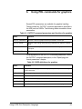
PDL command structure and components . . . . . . . . . . . . . . . . . . . . . . 1-3
Command lines . . . . . . . . . . . . . . . . . . . . . . . . . . . . . . . . . . . . . . 1-3
Components of a command . . . . . . . . . . . . . . . . . . . . . . . . . . . . 1-3
Command syntax . . . . . . . . . . . . . . . . . . . . . . . . . . . . . . . . . . . 1-12
Syntax rules . . . . . . . . . . . . . . . . . . . . . . . . . . . . . . . . . . 1-12
Command syntax conventions . . . . . . . . . . . . . . . . . . . . 1-14
Sample PDL commands . . . . . . . . . . . . . . . . . . . . . . . . . . . . . . 1-15
PDL command categories . . . . . . . . . . . . . . . . . . . . . . . . . . . . 1-16
The Job Source Library (JSL) . . . . . . . . . . . . . . . . . . . . . . . . . . . . . . . 1-17
What does a JSL specify? . . . . . . . . . . . . . . . . . . . . . . . . . . . . 1-18
JSL command levels . . . . . . . . . . . . . . . . . . . . . . . . . . . . . . . . 1-18
JDL name . . . . . . . . . . . . . . . . . . . . . . . . . . . . . . . . . . . 1-21
JDL or system level commands . . . . . . . . . . . . . . . . . . . 1-21
Coding system level commands with identifiers . 1-21
Coding other system level commands . . . . . . . . 1-24
Catalog level commands . . . . . . . . . . . . . . . . . . . . . . . . 1-26
Using LCDS Print Description Language
iii
Table of contents
Job or JDE level commands . . . . . . . . . . . . . . . . . . . . .
Coding job or JDE level commands . . . . . . . . . .
Comments . . . . . . . . . . . . . . . . . . . . . . . . . . . . . . . . . . . . . . . .
Ending a JSL . . . . . . . . . . . . . . . . . . . . . . . . . . . . . . . . . . . . . .
Sample completed JSL . . . . . . . . . . . . . . . . . . . . . . . . . . . . . . .
Before creating a JSL: considerations and decisions . . . . . . . .
Input data . . . . . . . . . . . . . . . . . . . . . . . . . . . . . . . . . . . .
Output specifications . . . . . . . . . . . . . . . . . . . . . . . . . . .
Special features . . . . . . . . . . . . . . . . . . . . . . . . . . . . . . .
Interactions between JSLs, catalogs, and jobs . . . . . . .
Paper sizes and page frames . . . . . . . . . . . . . . . . . . . .
Orientation . . . . . . . . . . . . . . . . . . . . . . . . . . . . . . . . . . . . . . . .
Fonts . . . . . . . . . . . . . . . . . . . . . . . . . . . . . . . . . . . . . . . . . . . . .
Overriding PDL commands . . . . . . . . . . . . . . . . . . . . . . . . . . .
Hints and tips . . . . . . . . . . . . . . . . . . . . . . . . . . . . . . . . . . . . . .
Coding a JSL . . . . . . . . . . . . . . . . . . . . . . . . . . . . . . . . . . . . . .
Before you start . . . . . . . . . . . . . . . . . . . . . . . . . . . . . . .
Short JSL coding procedure . . . . . . . . . . . . . . . . . . . . .
Full JSL coding procedure . . . . . . . . . . . . . . . . . . . . . . .
Sample online JSL . . . . . . . . . . . . . . . . . . . . . . . . . . . . .
Sample offline JSL . . . . . . . . . . . . . . . . . . . . . . . . . . . . .
Compiling a JSL . . . . . . . . . . . . . . . . . . . . . . . . . . . . . . . . . . . .
Compiling procedure . . . . . . . . . . . . . . . . . . . . . . . . . . .
Files produced by the compilation procedure . . . . . . . .
Correcting errors in a JSL . . . . . . . . . . . . . . . . . . . . . . .
Dynamic job descriptor entries (DJDEs) . . . . . . . . . . . . . . . . . . . . . . .
Benefits of using DJDEs . . . . . . . . . . . . . . . . . . . . . . . . . . . . . .
Dumps . . . . . . . . . . . . . . . . . . . . . . . . . . . . . . . . . . . . . . . . . . . . . . . . .
Online dump . . . . . . . . . . . . . . . . . . . . . . . . . . . . . . . . . . . . . . .
Starting and ending online dump sessions . . . . . . . . . .
Online dump format and content . . . . . . . . . . . . . . . . . .
Offline dump . . . . . . . . . . . . . . . . . . . . . . . . . . . . . . . . . . . . . . .
Starting and ending tape dump sessions . . . . . . . . . . . .
Offline dump format and content . . . . . . . . . . . . . . . . . .
Compatibility with other Xerox laser printing systems that use PDL . .
Printing highlight color applications on DP EPS . . . . . . . . . . . .
Other Xerox monochrome LPS jobs . . . . . . . . . . . . . . . . . . . . .
1-26
1-27
1-29
1-29
1-30
1-31
1-32
1-32
1-33
1-34
1-34
1-35
1-38
1-40
1-47
1-49
1-49
1-50
1-55
1-60
1-62
1-64
1-64
1-68
1-69
1-72
1-72
1-73
1-73
1-73
1-73
1-75
1-75
1-75
1-76
1-78
1-80
2. Specifying input parameters. . . . . . . . . . . . . . . . . . . . . . . . . . . . . . 2-1
Input data streams . . . . . . . . . . . . . . . . . . . . . . . . . . . . . . . . . . . . . . . . .
Input processing functions . . . . . . . . . . . . . . . . . . . . . . . . . . . . . . . . . . .
Input processing online . . . . . . . . . . . . . . . . . . . . . . . . . . . . . . . .
Forms control buffer (FCB) and vertical format control
processing . . . . . . . . . . . . . . . . . . . . . . . . . . . . . . . . . . . .
Example of an online JSL . . . . . . . . . . . . . . . . . . . . . . . .
Input processing offline . . . . . . . . . . . . . . . . . . . . . . . . . . . . . . . . . . . . .
iv
2-1
2-2
2-2
2-5
2-6
2-8
Using LCDS Print Description Language
Table of contents
Host computer tape formats . . . . . . . . . . . . . . . . . . . . . . . . . . . . 2-8
Tape codes . . . . . . . . . . . . . . . . . . . . . . . . . . . . . . . . . . . . . . . . . 2-9
Packed data formats . . . . . . . . . . . . . . . . . . . . . . . . . . . . . . . . . . 2-9
Record formats . . . . . . . . . . . . . . . . . . . . . . . . . . . . . . . . . . . . . . 2-9
Record structure . . . . . . . . . . . . . . . . . . . . . . . . . . . . . . . . . . . . 2-10
Multivolume processing . . . . . . . . . . . . . . . . . . . . . . . . . . . . . . 2-10
Input processing command descriptions . . . . . . . . . . . . . . . . . . . . . . . 2-11
BLOCK command . . . . . . . . . . . . . . . . . . . . . . . . . . . . . . . . . . . 2-12
BLOCK command parameters . . . . . . . . . . . . . . . . . . . . 2-12
BLOCK ADJUST . . . . . . . . . . . . . . . . . . . . . . . . . . . . . . 2-13
BLOCK CONSTANT . . . . . . . . . . . . . . . . . . . . . . . . . . . 2-13
BLOCK FORMAT . . . . . . . . . . . . . . . . . . . . . . . . . . . . . 2-14
BLOCK LENGTH . . . . . . . . . . . . . . . . . . . . . . . . . . . . . . 2-14
BLOCK LMULT . . . . . . . . . . . . . . . . . . . . . . . . . . . . . . . 2-15
BLOCK LTHFLD . . . . . . . . . . . . . . . . . . . . . . . . . . . . . . 2-15
BLOCK OFFSET . . . . . . . . . . . . . . . . . . . . . . . . . . . . . . 2-16
BLOCK POSTAMBLE . . . . . . . . . . . . . . . . . . . . . . . . . . 2-16
BLOCK PREAMBLE . . . . . . . . . . . . . . . . . . . . . . . . . . . 2-17
BLOCK ZERO . . . . . . . . . . . . . . . . . . . . . . . . . . . . . . . . 2-17
BLOCK command: points to note . . . . . . . . . . . . . . . . . 2-18
Block command example . . . . . . . . . . . . . . . . . . . . . . . . 2-18
CODE command . . . . . . . . . . . . . . . . . . . . . . . . . . . . . . . . . . . 2-19
CODE command parameters . . . . . . . . . . . . . . . . . . . . 2-19
CODE ASSIGN . . . . . . . . . . . . . . . . . . . . . . . . . . . . . . . 2-20
CODE DEFAULT . . . . . . . . . . . . . . . . . . . . . . . . . . . . . . 2-20
CODE SPACECODE . . . . . . . . . . . . . . . . . . . . . . . . . . . 2-22
DBCODE command . . . . . . . . . . . . . . . . . . . . . . . . . . . . . . . . . 2-22
DBCODE command parameters . . . . . . . . . . . . . . . . . . 2-23
DBCODE ASSIGN . . . . . . . . . . . . . . . . . . . . . . . . . . . . . 2-23
DBCODE DEFAULT . . . . . . . . . . . . . . . . . . . . . . . . . . . 2-24
DBCODE command: point to note . . . . . . . . . . . . . . . . . 2-24
IDEN command . . . . . . . . . . . . . . . . . . . . . . . . . . . . . . . . . . . . 2-24
IDEN command parameters . . . . . . . . . . . . . . . . . . . . . 2-25
IDEN DJPCC . . . . . . . . . . . . . . . . . . . . . . . . . . . . . . . . . 2-25
IDEN OFFSET . . . . . . . . . . . . . . . . . . . . . . . . . . . . . . . . 2-26
IDEN OPRINFO . . . . . . . . . . . . . . . . . . . . . . . . . . . . . . . 2-26
IDEN PREFIX . . . . . . . . . . . . . . . . . . . . . . . . . . . . . . . . 2-27
IDEN SKIP . . . . . . . . . . . . . . . . . . . . . . . . . . . . . . . . . . . 2-27
IDEN command example . . . . . . . . . . . . . . . . . . . . . . . . 2-28
KCODE command . . . . . . . . . . . . . . . . . . . . . . . . . . . . . . . . . . 2-28
KCODE command parameters . . . . . . . . . . . . . . . . . . . 2-28
KCODE ASSIGN . . . . . . . . . . . . . . . . . . . . . . . . . . . . . . 2-29
KCODE DEFAULT . . . . . . . . . . . . . . . . . . . . . . . . . . . . . 2-29
KCODE command: point to note . . . . . . . . . . . . . . . . . . 2-30
PCC command . . . . . . . . . . . . . . . . . . . . . . . . . . . . . . . . . . . . . 2-30
PCC command parameters . . . . . . . . . . . . . . . . . . . . . . 2-30
Using LCDS Print Description Language
v
Table of contents
PCC ADVTAPE . . . . . . . . . . . . . . . . . . . . . . . . . . . . . . .
PCC ASSIGN . . . . . . . . . . . . . . . . . . . . . . . . . . . . . . . . .
PCC DEFAULT . . . . . . . . . . . . . . . . . . . . . . . . . . . . . . .
PCC INITIAL . . . . . . . . . . . . . . . . . . . . . . . . . . . . . . . . .
PCC MASK . . . . . . . . . . . . . . . . . . . . . . . . . . . . . . . . . .
PCC command: points to note . . . . . . . . . . . . . . . . . . . .
PCC command example . . . . . . . . . . . . . . . . . . . . . . . .
RECORD command . . . . . . . . . . . . . . . . . . . . . . . . . . . . . . . . .
Record command parameters . . . . . . . . . . . . . . . . . . . .
RECORD ADJUST . . . . . . . . . . . . . . . . . . . . . . . . . . . .
RECORD CONSTANT . . . . . . . . . . . . . . . . . . . . . . . . .
RECORD FORMAT . . . . . . . . . . . . . . . . . . . . . . . . . . . .
RECORD LENGTH . . . . . . . . . . . . . . . . . . . . . . . . . . . .
RECORD LMULT . . . . . . . . . . . . . . . . . . . . . . . . . . . . .
RECORD LTHFLD . . . . . . . . . . . . . . . . . . . . . . . . . . . . .
RECORD OFFSET . . . . . . . . . . . . . . . . . . . . . . . . . . . .
RECORD POSTAMBLE . . . . . . . . . . . . . . . . . . . . . . . .
RECORD PREAMBLE . . . . . . . . . . . . . . . . . . . . . . . . . .
RECORD STRUCTURE . . . . . . . . . . . . . . . . . . . . . . . .
RECORD command: Points to note . . . . . . . . . . . . . . .
RECORD command example . . . . . . . . . . . . . . . . . . . .
SEFFNT command . . . . . . . . . . . . . . . . . . . . . . . . . . . . . . . . . .
SEFFNT command parameters . . . . . . . . . . . . . . . . . . .
SEFFNT SEFMAP . . . . . . . . . . . . . . . . . . . . . . . . . . . . .
SEFFNT MAP . . . . . . . . . . . . . . . . . . . . . . . . . . . . . . . .
SEFFNT command: points to note . . . . . . . . . . . . . . . .
SEFFNT command examples . . . . . . . . . . . . . . . . . . . .
TCODE command . . . . . . . . . . . . . . . . . . . . . . . . . . . . . . . . . .
TCODE command parameters . . . . . . . . . . . . . . . . . . .
TCODE DEFAULT . . . . . . . . . . . . . . . . . . . . . . . . . . . . .
TCODE TASSIGN . . . . . . . . . . . . . . . . . . . . . . . . . . . . .
TCODE TRESET . . . . . . . . . . . . . . . . . . . . . . . . . . . . . .
TCODE command examples . . . . . . . . . . . . . . . . . . . . .
VOLUME command . . . . . . . . . . . . . . . . . . . . . . . . . . . . . . . . .
VOLUME command parameters . . . . . . . . . . . . . . . . . .
VOLUME BMULT . . . . . . . . . . . . . . . . . . . . . . . . . . . . .
VOLUME CODE . . . . . . . . . . . . . . . . . . . . . . . . . . . . . .
VOLUME DBCODE . . . . . . . . . . . . . . . . . . . . . . . . . . . .
VOLUME DBCS . . . . . . . . . . . . . . . . . . . . . . . . . . . . . . .
VOLUME EMTYPE . . . . . . . . . . . . . . . . . . . . . . . . . . . .
VOLUME EOV . . . . . . . . . . . . . . . . . . . . . . . . . . . . . . . .
VOLUME EXPAGE . . . . . . . . . . . . . . . . . . . . . . . . . . . .
VOLUME HOST . . . . . . . . . . . . . . . . . . . . . . . . . . . . . . .
VOLUME KANJI . . . . . . . . . . . . . . . . . . . . . . . . . . . . . .
VOLUME KCODE . . . . . . . . . . . . . . . . . . . . . . . . . . . . .
VOLUME LABEL . . . . . . . . . . . . . . . . . . . . . . . . . . . . . .
vi
2-31
2-31
2-33
2-34
2-35
2-35
2-35
2-36
2-36
2-36
2-37
2-37
2-38
2-39
2-39
2-40
2-40
2-40
2-41
2-41
2-42
2-44
2-45
2-45
2-46
2-47
2-48
2-49
2-50
2-51
2-51
2-52
2-53
2-54
2-54
2-56
2-56
2-57
2-57
2-58
2-58
2-59
2-60
2-62
2-63
2-63
Using LCDS Print Description Language
Table of contents
VOLUME LCODE . . . . . . . . . . . . . . . . . . . . . . . . . . . . .
VOLUME LPACK . . . . . . . . . . . . . . . . . . . . . . . . . . . . . .
VOLUME MAXLAB . . . . . . . . . . . . . . . . . . . . . . . . . . . .
VOLUME MINLAB . . . . . . . . . . . . . . . . . . . . . . . . . . . . .
VOLUME OPTIMIZE . . . . . . . . . . . . . . . . . . . . . . . . . . .
VOLUME OSCHN . . . . . . . . . . . . . . . . . . . . . . . . . . . . .
VOLUME OSHDP . . . . . . . . . . . . . . . . . . . . . . . . . . . . .
VOLUME OSTLP . . . . . . . . . . . . . . . . . . . . . . . . . . . . . .
VOLUME RMULT . . . . . . . . . . . . . . . . . . . . . . . . . . . . .
VOLUME TCODE . . . . . . . . . . . . . . . . . . . . . . . . . . . . .
VOLUME UNPACK . . . . . . . . . . . . . . . . . . . . . . . . . . . .
VOLUME VCODE . . . . . . . . . . . . . . . . . . . . . . . . . . . . .
VOLUME command examples . . . . . . . . . . . . . . . . . . .
2-64
2-64
2-65
2-65
2-66
2-67
2-67
2-67
2-68
2-68
2-69
2-70
2-71
3. Using logical processing . . . . . . . . . . . . . . . . . . . . . . . . . . . . . . . . 3-1
Types of commands for logical processing . . . . . . . . . . . . . . . . . . . . . . 3-1
Test expressions . . . . . . . . . . . . . . . . . . . . . . . . . . . . . . . . . . . . . . . . . . 3-2
Coding a test expression . . . . . . . . . . . . . . . . . . . . . . . . . . . . . . 3-2
Logical processing commands that have TEST parameters . . . 3-4
Commands that define criteria and constants . . . . . . . . . . . . . . . . . . . . 3-4
TABLE command . . . . . . . . . . . . . . . . . . . . . . . . . . . . . . . . . . . . 3-4
TABLE command parameters . . . . . . . . . . . . . . . . . . . . . 3-5
TABLE CONSTANT . . . . . . . . . . . . . . . . . . . . . . . . . . . . . 3-5
TABLE MASK . . . . . . . . . . . . . . . . . . . . . . . . . . . . . . . . . 3-6
TABLE command: points to note . . . . . . . . . . . . . . . . . . . 3-7
TABLE command examples . . . . . . . . . . . . . . . . . . . . . . 3-7
CRITERIA command . . . . . . . . . . . . . . . . . . . . . . . . . . . . . . . . . 3-9
CRITERIA command modes . . . . . . . . . . . . . . . . . . . . . . 3-9
Using the CRITERIA command . . . . . . . . . . . . . . . . . . . 3-10
String comparisons . . . . . . . . . . . . . . . . . . . . . . . 3-11
CRITERIA command parameters . . . . . . . . . . . . . . . . . 3-14
CRITERIA CHANGE . . . . . . . . . . . . . . . . . . . . . . . . . . . 3-14
CRITERIA CONSTANT . . . . . . . . . . . . . . . . . . . . . . . . . 3-16
CRITERIA LINENUM . . . . . . . . . . . . . . . . . . . . . . . . . . . 3-17
CRITERIA VALUE . . . . . . . . . . . . . . . . . . . . . . . . . . . . . 3-18
Logical processing command descriptions . . . . . . . . . . . . . . . . . . . . . 3-22
BANNER command . . . . . . . . . . . . . . . . . . . . . . . . . . . . . . . . . 3-22
BANNER command parameters . . . . . . . . . . . . . . . . . . 3-23
BANNER HCOUNT . . . . . . . . . . . . . . . . . . . . . . . . . . . . 3-23
BANNER HJOBNO . . . . . . . . . . . . . . . . . . . . . . . . . . . . 3-24
BANNER HRPTNA . . . . . . . . . . . . . . . . . . . . . . . . . . . . 3-24
BANNER TCOUNT . . . . . . . . . . . . . . . . . . . . . . . . . . . . 3-25
BANNER TEST . . . . . . . . . . . . . . . . . . . . . . . . . . . . . . . 3-25
BANNER TYPE . . . . . . . . . . . . . . . . . . . . . . . . . . . . . . . 3-26
BANNER command: points to note . . . . . . . . . . . . . . . . 3-27
BANNER command examples . . . . . . . . . . . . . . . . . . . . 3-27
Using LCDS Print Description Language
vii
Table of contents
BSELECT and BDELETE commands . . . . . . . . . . . . . . . . . . .
BSELECT and BDELETE TEST parameter . . . . . . . . .
BSELECT and BDELETE commands: points to note . .
Examples . . . . . . . . . . . . . . . . . . . . . . . . . . . . . . . . . . . .
Example 1 . . . . . . . . . . . . . . . . . . . . . . . . . . . . . .
Example 2 . . . . . . . . . . . . . . . . . . . . . . . . . . . . . .
LMODIFY command . . . . . . . . . . . . . . . . . . . . . . . . . . . . . . . . .
LMODIFY command parameters . . . . . . . . . . . . . . . . . .
LMODIFY INK . . . . . . . . . . . . . . . . . . . . . . . . . . . . . . . .
LMODIFY SELECT . . . . . . . . . . . . . . . . . . . . . . . . . . . .
LMODIFY TEST . . . . . . . . . . . . . . . . . . . . . . . . . . . . . . .
Points to note: LMODIFY command . . . . . . . . . . . . . . .
RAUX command . . . . . . . . . . . . . . . . . . . . . . . . . . . . . . . . . . . .
RAUX TEST parameter . . . . . . . . . . . . . . . . . . . . . . . . .
RAUX command: points to note . . . . . . . . . . . . . . . . . .
RAUX command example . . . . . . . . . . . . . . . . . . . . . . .
RDELETE and RSELECT commands . . . . . . . . . . . . . . . . . . .
RSELECT and RDELETE TEST parameter . . . . . . . . .
RDELETE and RSELECT commands: point to note . .
RDELETE command example . . . . . . . . . . . . . . . . . . . .
RFEED command . . . . . . . . . . . . . . . . . . . . . . . . . . . . . . . . . . .
RFEED TEST parameter . . . . . . . . . . . . . . . . . . . . . . . .
RFEED command: points to note . . . . . . . . . . . . . . . . .
ROFFSET command . . . . . . . . . . . . . . . . . . . . . . . . . . . . . . . .
ROFFSET command parameters . . . . . . . . . . . . . . . . .
ROFFSET PASSES . . . . . . . . . . . . . . . . . . . . . . . . . . . .
ROFFSET TEST . . . . . . . . . . . . . . . . . . . . . . . . . . . . . .
ROFFSET command: points to note . . . . . . . . . . . . . . .
ROFFSET command example . . . . . . . . . . . . . . . . . . . .
RPAGE command . . . . . . . . . . . . . . . . . . . . . . . . . . . . . . . . . .
RPAGE command parameters . . . . . . . . . . . . . . . . . . .
RPAGE SIDE . . . . . . . . . . . . . . . . . . . . . . . . . . . . . . . . .
RPAGE TEST . . . . . . . . . . . . . . . . . . . . . . . . . . . . . . . .
RPAGE WHEN . . . . . . . . . . . . . . . . . . . . . . . . . . . . . . .
RPAGE command: points to note . . . . . . . . . . . . . . . . .
RPAGE command examples . . . . . . . . . . . . . . . . . . . . .
RRESUME and RSUSPEND commands . . . . . . . . . . . . . . . . .
RSUSPEND and RRESUME command parameters . . .
RSUSPEND and RRESUME BEGIN . . . . . . . . . . . . . . .
RSUSPEND and RRESUME TEST . . . . . . . . . . . . . . . .
RRESUME and RSUSPEND commands: points to
note . . . . . . . . . . . . . . . . . . . . . . . . . . . . . . . . . . . . . . . .
RSUSPEND and RRESUME example . . . . . . . . . . . . .
RSTACK command . . . . . . . . . . . . . . . . . . . . . . . . . . . . . . . . .
RSTACK delimiter modes . . . . . . . . . . . . . . . . . . . . . . .
Delimiter on accounting page . . . . . . . . . . . . . . . . . . . .
viii
3-28
3-28
3-29
3-29
3-29
3-30
3-31
3-31
3-31
3-32
3-32
3-33
3-33
3-34
3-34
3-34
3-35
3-35
3-36
3-36
3-37
3-37
3-38
3-39
3-40
3-40
3-41
3-41
3-42
3-43
3-43
3-43
3-45
3-45
3-46
3-46
3-49
3-49
3-49
3-50
3-50
3-52
3-53
3-53
3-54
Using LCDS Print Description Language
Table of contents
Status display . . . . . . . . . . . . . . . . . . . . . . . . . . . . . . . .
RSTACK command parameters . . . . . . . . . . . . . . . . . .
RSTACK ACCTINFO . . . . . . . . . . . . . . . . . . . . . . . . . . .
RSTACK DELIMITER . . . . . . . . . . . . . . . . . . . . . . . . . .
RSTACK HRPTNA . . . . . . . . . . . . . . . . . . . . . . . . . . . .
RSTACK PRINT . . . . . . . . . . . . . . . . . . . . . . . . . . . . . .
RSTACK TEST . . . . . . . . . . . . . . . . . . . . . . . . . . . . . . .
RSTACK command: points to note . . . . . . . . . . . . . . . .
RSTACK command example . . . . . . . . . . . . . . . . . . . . .
3-54
3-55
3-55
3-56
3-56
3-57
3-58
3-58
3-59
4. Specifying print format parameters . . . . . . . . . . . . . . . . . . . . . . . . 4-1
Print format command descriptions . . . . . . . . . . . . . . . . . . . . . . . . . . . . 4-1
ABNORMAL command . . . . . . . . . . . . . . . . . . . . . . . . . . . . . . . . 4-2
ABNORMAL command parameters . . . . . . . . . . . . . . . . . 4-2
ABNORMAL ACCTFEED . . . . . . . . . . . . . . . . . . . . . . . . 4-2
ABNORMAL CODE . . . . . . . . . . . . . . . . . . . . . . . . . . . . . 4-3
ABNORMAL ERROR . . . . . . . . . . . . . . . . . . . . . . . . . . . . 4-3
ABNORMAL IMISMATCH . . . . . . . . . . . . . . . . . . . . . . . . 4-5
ABNORMAL ISUBSTITUTE . . . . . . . . . . . . . . . . . . . . . . 4-6
ABNORMAL OTEXT . . . . . . . . . . . . . . . . . . . . . . . . . . . . 4-6
ABNORMAL REP . . . . . . . . . . . . . . . . . . . . . . . . . . . . . . 4-7
ABNORMAL SECURITY . . . . . . . . . . . . . . . . . . . . . . . . . 4-8
ACCT command . . . . . . . . . . . . . . . . . . . . . . . . . . . . . . . . . . . . . 4-9
ACCT command parameters . . . . . . . . . . . . . . . . . . . . . . 4-9
ACCT DEPT . . . . . . . . . . . . . . . . . . . . . . . . . . . . . . . . . . 4-9
ACCT USER . . . . . . . . . . . . . . . . . . . . . . . . . . . . . . . . . 4-10
ACCT command: points to note . . . . . . . . . . . . . . . . . . . 4-10
ACCT command example . . . . . . . . . . . . . . . . . . . . . . . 4-10
CME command . . . . . . . . . . . . . . . . . . . . . . . . . . . . . . . . . . . . . 4-11
CME command parameters . . . . . . . . . . . . . . . . . . . . . . 4-12
CME CONSTANT . . . . . . . . . . . . . . . . . . . . . . . . . . . . . 4-13
CME FONT . . . . . . . . . . . . . . . . . . . . . . . . . . . . . . . . . . 4-13
CME INK . . . . . . . . . . . . . . . . . . . . . . . . . . . . . . . . . . . . 4-14
CME LINE . . . . . . . . . . . . . . . . . . . . . . . . . . . . . . . . . . . 4-15
CME POSITION . . . . . . . . . . . . . . . . . . . . . . . . . . . . . . . 4-16
CME command: points to note . . . . . . . . . . . . . . . . . . . 4-16
CME command examples . . . . . . . . . . . . . . . . . . . . . . . 4-18
IDR command . . . . . . . . . . . . . . . . . . . . . . . . . . . . . . . . . . . . . . 4-19
IDR command parameters . . . . . . . . . . . . . . . . . . . . . . . 4-20
IDR ICATALOG . . . . . . . . . . . . . . . . . . . . . . . . . . . . . . . 4-20
IDR ILIST . . . . . . . . . . . . . . . . . . . . . . . . . . . . . . . . . . . . 4-21
IDR PALETTE . . . . . . . . . . . . . . . . . . . . . . . . . . . . . . . . 4-22
LINE command . . . . . . . . . . . . . . . . . . . . . . . . . . . . . . . . . . . . . 4-22
LINE command parameters . . . . . . . . . . . . . . . . . . . . . . 4-22
LINE BASELINE . . . . . . . . . . . . . . . . . . . . . . . . . . . . . . 4-23
LINE BLANKTYPE . . . . . . . . . . . . . . . . . . . . . . . . . . . . . 4-24
Using LCDS Print Description Language
ix
Table of contents
LINE DATA . . . . . . . . . . . . . . . . . . . . . . . . . . . . . . . . . .
LINE FCB . . . . . . . . . . . . . . . . . . . . . . . . . . . . . . . . . . . .
LINE FDATA . . . . . . . . . . . . . . . . . . . . . . . . . . . . . . . . .
LINE FONTINDEX . . . . . . . . . . . . . . . . . . . . . . . . . . . . .
LINE GDATA . . . . . . . . . . . . . . . . . . . . . . . . . . . . . . . . .
LINE INKINDEX . . . . . . . . . . . . . . . . . . . . . . . . . . . . . . .
LINE LPI . . . . . . . . . . . . . . . . . . . . . . . . . . . . . . . . . . . .
LINE MARGIN . . . . . . . . . . . . . . . . . . . . . . . . . . . . . . . .
LINE OVERPRINT . . . . . . . . . . . . . . . . . . . . . . . . . . . . .
LINE PCC . . . . . . . . . . . . . . . . . . . . . . . . . . . . . . . . . . .
LINE PCCTYPE . . . . . . . . . . . . . . . . . . . . . . . . . . . . . . .
LINE VFU . . . . . . . . . . . . . . . . . . . . . . . . . . . . . . . . . . . .
LINE command: points to note . . . . . . . . . . . . . . . . . . .
LINE command examples . . . . . . . . . . . . . . . . . . . . . . .
MESSAGE command . . . . . . . . . . . . . . . . . . . . . . . . . . . . . . . .
MESSAGE command parameters . . . . . . . . . . . . . . . . .
MESSAGE ITEXT . . . . . . . . . . . . . . . . . . . . . . . . . . . . .
MESSAGE OTEXT . . . . . . . . . . . . . . . . . . . . . . . . . . . .
MESSAGE command: points to note . . . . . . . . . . . . . . .
MESSAGE command example . . . . . . . . . . . . . . . . . . .
OUTPUT command . . . . . . . . . . . . . . . . . . . . . . . . . . . . . . . . .
OUTPUT command parameters . . . . . . . . . . . . . . . . . .
OUTPUT BFORM . . . . . . . . . . . . . . . . . . . . . . . . . . . . .
OUTPUT BINDING . . . . . . . . . . . . . . . . . . . . . . . . . . . .
OUTPUT COLLATE . . . . . . . . . . . . . . . . . . . . . . . . . . . .
OUTPUT COPIES . . . . . . . . . . . . . . . . . . . . . . . . . . . . .
OUTPUT COVER . . . . . . . . . . . . . . . . . . . . . . . . . . . . .
OUTPUT CYCLEFORMS . . . . . . . . . . . . . . . . . . . . . . .
OUTPUT DENSITY . . . . . . . . . . . . . . . . . . . . . . . . . . . .
OUTPUT DESTINATION . . . . . . . . . . . . . . . . . . . . . . . .
OUTPUT DUPLEX . . . . . . . . . . . . . . . . . . . . . . . . . . . . .
OUTPUT FACEUP . . . . . . . . . . . . . . . . . . . . . . . . . . . .
OUTPUT FEED . . . . . . . . . . . . . . . . . . . . . . . . . . . . . . .
OUTPUT FORMAT . . . . . . . . . . . . . . . . . . . . . . . . . . . .
OUTPUT FORMS . . . . . . . . . . . . . . . . . . . . . . . . . . . . .
OUTPUT GRAPHICS . . . . . . . . . . . . . . . . . . . . . . . . . .
OUTPUT IDFAULT . . . . . . . . . . . . . . . . . . . . . . . . . . . .
OUTPUT IDR . . . . . . . . . . . . . . . . . . . . . . . . . . . . . . . . .
OUTPUT IMAGE . . . . . . . . . . . . . . . . . . . . . . . . . . . . . .
OUTPUT INVERT . . . . . . . . . . . . . . . . . . . . . . . . . . . . .
OUTPUT IRESULT . . . . . . . . . . . . . . . . . . . . . . . . . . . .
OUTPUT LOGO . . . . . . . . . . . . . . . . . . . . . . . . . . . . . . .
OUTPUT MODIFY . . . . . . . . . . . . . . . . . . . . . . . . . . . . .
OUTPUT NTO1 . . . . . . . . . . . . . . . . . . . . . . . . . . . . . . .
OUTPUT NUMBER . . . . . . . . . . . . . . . . . . . . . . . . . . . .
OUTPUT OFFSET . . . . . . . . . . . . . . . . . . . . . . . . . . . . .
x
4-25
4-25
4-26
4-27
4-28
4-29
4-30
4-31
4-31
4-33
4-34
4-35
4-36
4-37
4-38
4-39
4-39
4-40
4-41
4-41
4-42
4-42
4-44
4-45
4-48
4-48
4-49
4-49
4-51
4-51
4-52
4-52
4-53
4-54
4-55
4-56
4-57
4-58
4-59
4-60
4-61
4-62
4-63
4-64
4-66
4-67
Using LCDS Print Description Language
Table of contents
OUTPUT OSTK . . . . . . . . . . . . . . . . . . . . . . . . . . . . . . . 4-68
OUTPUT PAPERSIZE . . . . . . . . . . . . . . . . . . . . . . . . . . 4-73
OUTPUT PURGE . . . . . . . . . . . . . . . . . . . . . . . . . . . . . 4-74
OUTPUT SF1FUNCTION . . . . . . . . . . . . . . . . . . . . . . . 4-75
OUTPUT SF2FUNCTION . . . . . . . . . . . . . . . . . . . . . . . 4-76
OUTPUT SHIFT . . . . . . . . . . . . . . . . . . . . . . . . . . . . . . . 4-76
OUTPUT SIZING . . . . . . . . . . . . . . . . . . . . . . . . . . . . . . 4-77
OUTPUT STAPLE . . . . . . . . . . . . . . . . . . . . . . . . . . . . . 4-79
OUTPUT STOCKS . . . . . . . . . . . . . . . . . . . . . . . . . . . . 4-80
OUTPUT SYSPPR . . . . . . . . . . . . . . . . . . . . . . . . . . . . 4-81
OUTPUT TMODE . . . . . . . . . . . . . . . . . . . . . . . . . . . . . 4-83
OUTPUT TRANS . . . . . . . . . . . . . . . . . . . . . . . . . . . . . . 4-87
OUTPUT UNITS . . . . . . . . . . . . . . . . . . . . . . . . . . . . . . 4-87
OUTPUT XSHIFT . . . . . . . . . . . . . . . . . . . . . . . . . . . . . 4-88
OUTPUT command: point to note . . . . . . . . . . . . . . . . . 4-89
OUTPUT command examples . . . . . . . . . . . . . . . . . . . . 4-89
PDE command . . . . . . . . . . . . . . . . . . . . . . . . . . . . . . . . . . . . . 4-91
Standard PDEs . . . . . . . . . . . . . . . . . . . . . . . . . . . . . . . 4-91
PDE command parameters . . . . . . . . . . . . . . . . . . . . . . 4-93
PDE BEGIN . . . . . . . . . . . . . . . . . . . . . . . . . . . . . . . . . . 4-93
PDE FONTS . . . . . . . . . . . . . . . . . . . . . . . . . . . . . . . . . 4-96
PDE PMODE . . . . . . . . . . . . . . . . . . . . . . . . . . . . . . . . . 4-97
PDE command: points to note . . . . . . . . . . . . . . . . . . . . 4-98
PDE command examples . . . . . . . . . . . . . . . . . . . . . . . 4-98
ROUTE command . . . . . . . . . . . . . . . . . . . . . . . . . . . . . . . . . . 4-99
ROUTE command parameters . . . . . . . . . . . . . . . . . . . 4-99
ROUTE RFORM . . . . . . . . . . . . . . . . . . . . . . . . . . . . . 4-100
ROUTE RTEXT . . . . . . . . . . . . . . . . . . . . . . . . . . . . . . 4-100
ROUTE command example . . . . . . . . . . . . . . . . . . . . . 4-103
STOCKSET command . . . . . . . . . . . . . . . . . . . . . . . . . . . . . . 4-103
STOCKSET command parameters . . . . . . . . . . . . . . . 4-104
STOCKSET ASSIGN . . . . . . . . . . . . . . . . . . . . . . . . . . 4-104
STOCKSET INIFEED . . . . . . . . . . . . . . . . . . . . . . . . . 4-105
STOCKSET SYSPAGE . . . . . . . . . . . . . . . . . . . . . . . . 4-105
STOCKSET command example . . . . . . . . . . . . . . . . . 4-107
VFU command . . . . . . . . . . . . . . . . . . . . . . . . . . . . . . . . . . . . 4-108
VFU command parameters . . . . . . . . . . . . . . . . . . . . . 4-108
VFU ASSIGN . . . . . . . . . . . . . . . . . . . . . . . . . . . . . . . . 4-108
VFU BOF . . . . . . . . . . . . . . . . . . . . . . . . . . . . . . . . . . . 4-109
VFU TOF . . . . . . . . . . . . . . . . . . . . . . . . . . . . . . . . . . . 4-109
VFU command: points to note . . . . . . . . . . . . . . . . . . . 4-110
VFU command example . . . . . . . . . . . . . . . . . . . . . . . 4-111
5. Using Dynamic Job Descriptor Entries (DJDEs) . . . . . . . . . . . . . 5-1
Using the IDEN command to enable DJDEs . . . . . . . . . . . . . . . . . . . . . 5-1
Specifying DJDE records . . . . . . . . . . . . . . . . . . . . . . . . . . . . . . . . . . . 5-2
Using LCDS Print Description Language
xi
Table of contents
Application of DJDEs . . . . . . . . . . . . . . . . . . . . . . . . . . . . . . . . . . . . . . . 5-3
DJDE operator information pages . . . . . . . . . . . . . . . . . . . . . . . . . . . . . 5-5
Restrictions on job parameter modification . . . . . . . . . . . . . . . . . . . . . . 5-6
Considerations and cautions for using DJDEs . . . . . . . . . . . . . . . . . . . 5-8
Types of DJDEs . . . . . . . . . . . . . . . . . . . . . . . . . . . . . . . . . . . . . . . . . 5-10
DJDE descriptions . . . . . . . . . . . . . . . . . . . . . . . . . . . . . . . . . . . . . . . . 5-14
ALTER DJDE . . . . . . . . . . . . . . . . . . . . . . . . . . . . . . . . . . . . . . 5-14
ALTER DJDE: point to note . . . . . . . . . . . . . . . . . . . . . . 5-15
Examples of ALTER DJDE . . . . . . . . . . . . . . . . . . . . . . 5-15
ASSIGN DJDE . . . . . . . . . . . . . . . . . . . . . . . . . . . . . . . . . . . . . 5-16
ASSIGN DJDE: points to note . . . . . . . . . . . . . . . . . . . . 5-16
BATCH DJDE . . . . . . . . . . . . . . . . . . . . . . . . . . . . . . . . . . . . . . 5-16
BATCH DJDE: points to note . . . . . . . . . . . . . . . . . . . . . 5-17
BEGIN DJDE . . . . . . . . . . . . . . . . . . . . . . . . . . . . . . . . . . . . . . 5-17
BEGIN DJDE: points to note . . . . . . . . . . . . . . . . . . . . . 5-18
BFORM DJDE . . . . . . . . . . . . . . . . . . . . . . . . . . . . . . . . . . . . . 5-18
BFORM DJDE: points to note . . . . . . . . . . . . . . . . . . . . 5-19
BOF DJDE . . . . . . . . . . . . . . . . . . . . . . . . . . . . . . . . . . . . . . . . 5-20
BOF DJDE: points to note . . . . . . . . . . . . . . . . . . . . . . . 5-20
C (text) DJDE . . . . . . . . . . . . . . . . . . . . . . . . . . . . . . . . . . . . . . 5-20
C (text) DJDE: points to note . . . . . . . . . . . . . . . . . . . . . 5-21
CANCEL DJDE . . . . . . . . . . . . . . . . . . . . . . . . . . . . . . . . . . . . . 5-21
COLLATE DJDE . . . . . . . . . . . . . . . . . . . . . . . . . . . . . . . . . . . . 5-22
COLLATE DJDE: point to note . . . . . . . . . . . . . . . . . . . 5-22
COPIES DJDE . . . . . . . . . . . . . . . . . . . . . . . . . . . . . . . . . . . . . 5-22
COPIES DJDE: points to note . . . . . . . . . . . . . . . . . . . . 5-23
DATA DJDE . . . . . . . . . . . . . . . . . . . . . . . . . . . . . . . . . . . . . . . 5-23
DATA DJDE: point to note . . . . . . . . . . . . . . . . . . . . . . . 5-23
DEPT DJDE . . . . . . . . . . . . . . . . . . . . . . . . . . . . . . . . . . . . . . . 5-24
DEPT DJDE: points to note . . . . . . . . . . . . . . . . . . . . . . 5-24
DESTINATION DJDE . . . . . . . . . . . . . . . . . . . . . . . . . . . . . . . . 5-24
DESTINATION DJDE: points to note . . . . . . . . . . . . . . . 5-25
DUPLEX DJDE . . . . . . . . . . . . . . . . . . . . . . . . . . . . . . . . . . . . . 5-25
END DJDE . . . . . . . . . . . . . . . . . . . . . . . . . . . . . . . . . . . . . . . . 5-26
END DJDE: points to note . . . . . . . . . . . . . . . . . . . . . . . 5-26
EOF DJDE . . . . . . . . . . . . . . . . . . . . . . . . . . . . . . . . . . . . . . . . 5-26
EOF DJDE: point to note . . . . . . . . . . . . . . . . . . . . . . . . 5-26
FEED DJDE . . . . . . . . . . . . . . . . . . . . . . . . . . . . . . . . . . . . . . . 5-27
FDATA DJDE . . . . . . . . . . . . . . . . . . . . . . . . . . . . . . . . . . . . . . 5-27
FILE DJDE . . . . . . . . . . . . . . . . . . . . . . . . . . . . . . . . . . . . . . . . 5-28
FILE DJDE: points to note . . . . . . . . . . . . . . . . . . . . . . . 5-29
FILE DJDE processing . . . . . . . . . . . . . . . . . . . . . . . . . 5-29
FONTINDEX DJDE . . . . . . . . . . . . . . . . . . . . . . . . . . . . . . . . . 5-33
FONTINDEX DJDE: points to note . . . . . . . . . . . . . . . . 5-34
FONTS DJDE . . . . . . . . . . . . . . . . . . . . . . . . . . . . . . . . . . . . . . 5-35
FONTS DJDE: points to note . . . . . . . . . . . . . . . . . . . . . 5-36
xii
Using LCDS Print Description Language
Table of contents
FORMAT DJDE . . . . . . . . . . . . . . . . . . . . . . . . . . . . . . . . . . . .
FORMAT DJDE: points to note . . . . . . . . . . . . . . . . . . .
FORM[S] DJDE . . . . . . . . . . . . . . . . . . . . . . . . . . . . . . . . . . . .
FORM[S] DJDE: point to note . . . . . . . . . . . . . . . . . . . .
GDATA DJDE . . . . . . . . . . . . . . . . . . . . . . . . . . . . . . . . . . . . . .
GRAPHIC DJDE . . . . . . . . . . . . . . . . . . . . . . . . . . . . . . . . . . . .
GRAPHIC DJDE: points to note . . . . . . . . . . . . . . . . . .
ICATALOG DJDE . . . . . . . . . . . . . . . . . . . . . . . . . . . . . . . . . . .
ICATALOG DJDE example . . . . . . . . . . . . . . . . . . . . . .
IDFAULT DJDE . . . . . . . . . . . . . . . . . . . . . . . . . . . . . . . . . . . .
IDFAULT DJDE: point to note . . . . . . . . . . . . . . . . . . . .
IDR DJDE . . . . . . . . . . . . . . . . . . . . . . . . . . . . . . . . . . . . . . . . .
ILIST DJDE . . . . . . . . . . . . . . . . . . . . . . . . . . . . . . . . . . . . . . . .
ILIST DJDE example . . . . . . . . . . . . . . . . . . . . . . . . . . .
IMAGE DJDE . . . . . . . . . . . . . . . . . . . . . . . . . . . . . . . . . . . . . .
INKINDEX DJDE . . . . . . . . . . . . . . . . . . . . . . . . . . . . . . . . . . .
INVERT DJDE . . . . . . . . . . . . . . . . . . . . . . . . . . . . . . . . . . . . .
IRESULT DJDE . . . . . . . . . . . . . . . . . . . . . . . . . . . . . . . . . . . .
IRESULT DJDE: points to note . . . . . . . . . . . . . . . . . . .
ITEXT DJDE . . . . . . . . . . . . . . . . . . . . . . . . . . . . . . . . . . . . . . .
ITEXT DJDE: points to note . . . . . . . . . . . . . . . . . . . . . .
JDE DJDE . . . . . . . . . . . . . . . . . . . . . . . . . . . . . . . . . . . . . . . .
JDE DJDE: points to note . . . . . . . . . . . . . . . . . . . . . . .
JDL DJDE . . . . . . . . . . . . . . . . . . . . . . . . . . . . . . . . . . . . . . . . .
JDL DJDE: points to note . . . . . . . . . . . . . . . . . . . . . . .
LOGO DJDE . . . . . . . . . . . . . . . . . . . . . . . . . . . . . . . . . . . . . . .
LOGO DJDE: points to note . . . . . . . . . . . . . . . . . . . . .
LPI DJDE . . . . . . . . . . . . . . . . . . . . . . . . . . . . . . . . . . . . . . . . .
LPI DJDE: point to note . . . . . . . . . . . . . . . . . . . . . . . . .
MAP DJDE . . . . . . . . . . . . . . . . . . . . . . . . . . . . . . . . . . . . . . . .
MARGIN DJDE . . . . . . . . . . . . . . . . . . . . . . . . . . . . . . . . . . . . .
MARGIN DJDE: points to note . . . . . . . . . . . . . . . . . . .
MODIFY DJDE . . . . . . . . . . . . . . . . . . . . . . . . . . . . . . . . . . . . .
MODIFY DJDE: points to note . . . . . . . . . . . . . . . . . . . .
NUMBER DJDE . . . . . . . . . . . . . . . . . . . . . . . . . . . . . . . . . . . .
NUMBER DJDE: point to note . . . . . . . . . . . . . . . . . . . .
NUMBER DJDE example . . . . . . . . . . . . . . . . . . . . . . .
OTEXT DJDE . . . . . . . . . . . . . . . . . . . . . . . . . . . . . . . . . . . . . .
OTEXT DJDE: point to note . . . . . . . . . . . . . . . . . . . . . .
OVERPRINT DJDE . . . . . . . . . . . . . . . . . . . . . . . . . . . . . . . . .
OVERPRINT DJDE: points to note . . . . . . . . . . . . . . . .
PALETTE DJDE . . . . . . . . . . . . . . . . . . . . . . . . . . . . . . . . . . . .
PALETTE DJDE example . . . . . . . . . . . . . . . . . . . . . . .
PMODE DJDE . . . . . . . . . . . . . . . . . . . . . . . . . . . . . . . . . . . . .
PMODE DJDE: point to note . . . . . . . . . . . . . . . . . . . . .
RFORM DJDE . . . . . . . . . . . . . . . . . . . . . . . . . . . . . . . . . . . . .
Using LCDS Print Description Language
5-37
5-37
5-38
5-38
5-39
5-39
5-41
5-42
5-42
5-42
5-43
5-43
5-43
5-44
5-44
5-45
5-46
5-47
5-47
5-48
5-48
5-48
5-49
5-49
5-50
5-50
5-52
5-52
5-53
5-53
5-53
5-54
5-54
5-55
5-55
5-56
5-58
5-58
5-59
5-59
5-60
5-60
5-61
5-61
5-61
5-61
xiii
Table of contents
RFORM DJDE: points to note . . . . . . . . . . . . . . . . . . . .
RTEXT DJDE . . . . . . . . . . . . . . . . . . . . . . . . . . . . . . . . . . . . . .
RTEXT DJDE example . . . . . . . . . . . . . . . . . . . . . . . . .
SAVE DJDE . . . . . . . . . . . . . . . . . . . . . . . . . . . . . . . . . . . . . . .
SAVE DJDE: point to note . . . . . . . . . . . . . . . . . . . . . . .
SEFMAP DJDE . . . . . . . . . . . . . . . . . . . . . . . . . . . . . . . . . . . .
SEFMAP DJDE: points to note . . . . . . . . . . . . . . . . . . .
SEFMAP DJDE examples . . . . . . . . . . . . . . . . . . . . . . .
SF1FUNCTION DJDE . . . . . . . . . . . . . . . . . . . . . . . . . . . . . . .
SF2FUNCTION DJDE . . . . . . . . . . . . . . . . . . . . . . . . . . . . . . .
SHIFT DJDE . . . . . . . . . . . . . . . . . . . . . . . . . . . . . . . . . . . . . . .
SHIFT DJDE: points to note . . . . . . . . . . . . . . . . . . . . .
SIDE DJDE . . . . . . . . . . . . . . . . . . . . . . . . . . . . . . . . . . . . . . . .
SIDE DJDE: points to note . . . . . . . . . . . . . . . . . . . . . .
STOCKS DJDE . . . . . . . . . . . . . . . . . . . . . . . . . . . . . . . . . . . .
STOCKS DJDE: point to note . . . . . . . . . . . . . . . . . . . .
TMODE DJDE . . . . . . . . . . . . . . . . . . . . . . . . . . . . . . . . . . . . .
TOF DJDE . . . . . . . . . . . . . . . . . . . . . . . . . . . . . . . . . . . . . . . .
TOF DJDE: points to note . . . . . . . . . . . . . . . . . . . . . . .
TRANS DJDE . . . . . . . . . . . . . . . . . . . . . . . . . . . . . . . . . . . . . .
TRANS DJDE: points to note . . . . . . . . . . . . . . . . . . . . .
XMP DJDE . . . . . . . . . . . . . . . . . . . . . . . . . . . . . . . . . . . . . . . .
XSHIFT DJDE . . . . . . . . . . . . . . . . . . . . . . . . . . . . . . . . . . . . .
5-62
5-62
5-63
5-64
5-64
5-64
5-65
5-65
5-66
5-67
5-67
5-68
5-68
5-69
5-70
5-70
5-70
5-71
5-71
5-72
5-72
5-73
5-73
6. Using PDL commands for graphics . . . . . . . . . . . . . . . . . . . . . . . . 6-1
Input for graphics . . . . . . . . . . . . . . . . . . . . . . . . . . . . . . . . . . . . . . . . . .
Error handling for graphics . . . . . . . . . . . . . . . . . . . . . . . . . . . . . . . . . .
Graphic processing modes . . . . . . . . . . . . . . . . . . . . . . . . . . . . . . . . . .
Formats for graphic data . . . . . . . . . . . . . . . . . . . . . . . . . . . . . . . . . . . .
Impact of graphics on system performance . . . . . . . . . . . . . . . . . . . . .
Graphics features restrictions . . . . . . . . . . . . . . . . . . . . . . . . . . . . . . . .
6-2
6-3
6-3
6-4
6-6
6-6
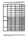
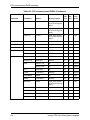
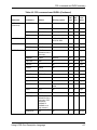
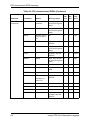
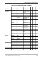
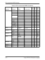
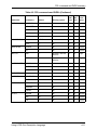
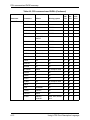
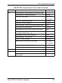
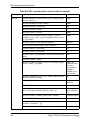
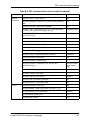
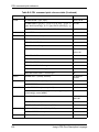
A. PDL command and DJDE summary . . . . . . . . . . . . . . . . . . . . . . . .A-1
Summary table of PDL commands and DJDEs . . . . . . . . . . . . . . . . . . A-2
B. PDL command quick reference . . . . . . . . . . . . . . . . . . . . . . . . . . .B-1
PDL command Quick Reference table . . . . . . . . . . . . . . . . . . . . . . . . . B-2
C. Character code assignments . . . . . . . . . . . . . . . . . . . . . . . . . . . . .C-1
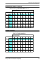
IBM BCD code set . . . . . . . . . . . . . . . . . . . . . . . . . . . . . . . . . . . . . . . . .
Honeywell/Bull 200 and 2000 BCD code set . . . . . . . . . . . . . . . . . . . . .
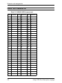
Honeywell/Bull 6000 BCD code set . . . . . . . . . . . . . . . . . . . . . . . . . . . .
Fieldata translation . . . . . . . . . . . . . . . . . . . . . . . . . . . . . . . . . . . . . . . .
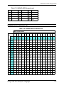
UNIVAC ASCII character set . . . . . . . . . . . . . . . . . . . . . . . . . . . . . . . . .
Standard ASCII character set . . . . . . . . . . . . . . . . . . . . . . . . . . . . . . . .
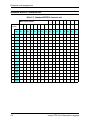
Standard EBCDIC character set . . . . . . . . . . . . . . . . . . . . . . . . . . . . . .
xiv
C-2
C-2
C-3
C-3
C-4
C-5
C-6
Using LCDS Print Description Language
Table of contents
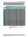
Xerox EBCDIC to extended ASCII hexadecimal translation values . . . C-7
D. Offline specifications. . . . . . . . . . . . . . . . . . . . . . . . . . . . . . . . . . . .D-1
Input unpacking examples . . . . . . . . . . . . . . . . . . . . . . . . . . . . . . . . . . .
Valid host computer and label specifications . . . . . . . . . . . . . . . . . . . .
Host system JDLs on system software CD . . . . . . . . . . . . . . . . . . . . . .
LPS tape label format . . . . . . . . . . . . . . . . . . . . . . . . . . . . . . . . . . . . . .
D-1
D-2
D-3
D-4
Glossary . . . . . . . . . . . . . . . . . . . . . . . . . . . . . . . . . . . . . . . Glossary-1
Index . . . . . . . . . . . . . . . . . . . . . . . . . . . . . . . . . . . . . . . . . . . . . Index-1
Using LCDS Print Description Language
xv
Table of contents
xvi
Using LCDS Print Description Language
Laser safety
WARNING
Adjustments, use of controls, or performance of procedures
other than those specified herein may result in hazardous
light exposure.
The Xerox DocuPrint printers are certified to comply with the
performance standards of the U.S. Department of Health,
Education, and Welfare for Class 1 laser products. Class 1 laser
products do not emit hazardous radiation. The DocuPrint printers
do not emit hazardous radiation, because the laser beam is
completely enclosed during all modes of customer operation.
The laser danger labels on the system are for Xerox service
representatives and are on or near panels or shields that must
be removed with a tool. DO NOT REMOVE LABELED PANELS
OR PANELS NEAR LABELS. ONLY XEROX SERVICE
REPRESENTATIVES HAVE ACCESS TO THESE PANELS.
Ozone information: U. S. only
This product produces ozone during normal operation. The
amount of ozone produced depends on print volume. Ozone is
heavier than air. The environmental parameters specified in the
Xerox installation instructions ensure that concentration levels
are within safe limits. If you need additional information
concerning ozone, call 1-800-828-6571 to request the Xerox
publication 600P83222, OZONE.
Using LCDS Print Description Language
xvii
Laser safety
Operation safety: U. S.
Your Xerox equipment and supplies have been designed and
tested to meet strict safety requirements. They have been
approved by safety agencies, and they comply with
environmental standards. Please observe the following
precautions to ensure your continued safety.
WARNING
Improper connection of the equipment grounding conductor
may result in risk of electrical shock.
•
Always connect equipment to a properly grounded electrical
outlet. If in doubt, have the outlet checked by a qualified
electrician.
•
Never use a ground adapter plug to connect equipment to an
electrical outlet that lacks a ground connection terminal.
•
Always place equipment on a solid support surface with
adequate strength for its weight.
•
Always use materials and supplies specifically designed for
your Xerox equipment. Use of unsuitable materials may result
in poor performance and may create a hazardous situation.
•
Never move either the printer or the printer controller without
first contacting Xerox for approval.
•
Never attempt any maintenance that is not specifically
described in this documentation.
•
Never remove any covers or guards that are fastened with
screws. There are no operator-serviceable areas within these
covers.
•
Never override electrical or mechanical interlocks.
•
Never use supplies or cleaning materials for other than their
intended purposes. Keep all materials out of the reach of
children.
•
Never operate the equipment if you notice unusual noises or
odors. Disconnect the power cord from the electrical outlet
and call service to correct the problem.
If you need any additional safety information concerning the
equipment or materials Xerox supplies, call Xerox Product
Safety at the following toll-free number in the United States:
1-800-828-6571
xviii
Using LCDS Print Description Language
Laser safety
For customers outside the United States, contact your local
Xerox representative or operating company.
Operation safety: Europe
This Xerox product and supplies are manufactured, tested and
certified to strict safety regulations, electromagnetic regulations
and established environmental standards.
Any unauthorized alteration, which may include the addition of
new functions or connection of external devices, may impact the
product certification.
Please contact your Xerox representative for more information.
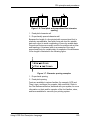
Warning markings
All warning instructions marked on or supplied with the product
should be followed.
This WARNING alerts users to areas of the product where there
is the possibility of personal damage.
This WARNING alerts users to areas of the product where there
are heated surfaces, which should not be touched.
Electrical supply
This product shall be operated from the type of electrical supply
indicated on the data plate label of the product. If you are not
sure that your electrical supply meets the requirements, please
consult your local power company for advice.
Using LCDS Print Description Language
xix
Laser safety
WARNING
This product must be connected to a protective earth
circuit.
This product is supplied with a plug that has a protective earth
pin. This plug fits only into an earthed electrical outlet. This is a
safety feature. Always connect equipment to a properly grounded
electrical outlet. If in doubt, have the outlet checked by a qualified
electrician.
To disconnect all electrical power to the product, the disconnect
device is the power cord. Remove the plug from the electrical
outlet.
Ventilation
Slots and openings in the enclosure of the product are provided
for ventilation. Do not block or cover the ventilation vents, as this
could result in the product overheating.
This product should not be placed in a built-in installation unless
proper ventilation is provided, please contact your Xerox
representative for advice.
Never push objects of any kind into the ventilation vents of the
product.
Operator accessible areas
This product has been designed to restrict operator access to
safe areas only. Operator access to hazardous areas is
restricted with covers or guards, which would require a tool to
remove. Never remove these covers or guards.
xx
Using LCDS Print Description Language
Laser safety
Maintenance
Any operator product maintenance procedures will be described
in the user documentation supplied with the product. Do not
carry out any maintenance on the product, which is not
described in the customer documentation.
Before cleaning your product
Before cleaning this product, unplug the product from the
electrical outlet. Always use materials specifically designated for
this product, the use of other materials may result in poor
performance and may create a hazardous situation. Do not use
aerosol cleaners, they may be flammable under certain
circumstances.
CE mark: Europe only
January 1, 1995: Council Directive 73/23/EEC, amended by
Council Directive 93/68/EEC, approximation of the laws of the
member states related to low voltage equipment.
January 1, 1996: Council Directive 89/336/EEC, approximation
of the laws of the member states related to electromagnetic
compatibility.
March 9, 1999: Council Directive 99/5/EC, on radio equipment
and telecommunications terminal equipment and the mutual
recognition of their conformity.
A full declaration of conformity, defining the relevant directives
and referenced standards, can be obtained from your Xerox
representative.
In order to allow this equipment to operate in proximity to
Industrial, Scientific and Medical (ISM) equipment, the external
radiation for the ISM equipment may have to be limited or special
mitigation measures taken.
Using LCDS Print Description Language
xxi
Laser safety
This is a Class A product. In a domestic environment this product
may cause radio frequency interference, in which case the user
may be required to take adequate measures.
Shielded interface cables must be used with this product to
maintain compliance with Council Directive 89/36/EEC.
For further information
For more information on Environment, Health and Safety in
relation to this Xerox product and supplies, please contact the
following customer help lines:
Europe: +44 1707 353434
USA: 1-800-828-6571
Canada: 1-800-828-6571
xxii
Using LCDS Print Description Language
Introduction
Using LCDS Print Description Language provides information on
how to use PDL to program LCDS job descriptions that can be
used on the Xerox DocuPrint 75/90 and 100/115/135/155/180
Enterprise Printing Systems, the DocuPrint 75 MX, and other
Xerox laser printing systems.
Contents
Before using this documentation, become familiar with its
contents and conventions.
The topics discussed in this guide include:
•
Explanation of a Job Source Library (JSL), including required
and optional commands and components
•
Rules and guidelines for coding LCDS PDL commands
•
Procedures for creating and compiling a JSL
•
Syntax and explanation of each LCDS PDL command,
parameter, and DJDE
•
Explanation of Dynamic Job Descriptor Entries (DJDEs) and
the process for inserting them into the data stream
•
Reference list of all PDL and DJDE commands, including
online and offline usage, parameters, and the Xerox printing
systems that support them
A glossary and index are also provided.
Focus of this
guide
This documentation describes LCDS Print Description Language
as it applies to the DocuPrint 100/115/135/155/180 and 75/90
EPS, and DocuPrint 75 MX. Except where otherwise noted, the
PDL information contained in this documentation also applies to
the following families of Xerox Laser Printing Systems that print
LCDS data:
Xerox 180, 180MX, 96, and 96MX Laser Printing Systems
Using LCDS Print Description Language
xxiii
Introduction
The following families of printing systems support subsets of the
PDL commands that can be used on the DP EPS.
•
Xerox 4635 and 4635 MX Laser Printing Systems
•
Xerox 4850 and 4890 HighLight Color Laser Printing
Systems
•
Xerox DocuPrint 92C HighLight Color Laser Printing System
•
Xerox 4050, 4090, and 4650 Laser Printing Systems
•
Xerox 9790 and 8790 Laser Printing Systems
Refer to appendix A, “PDL command and DJDE summary,” for
information on which laser printer families support the different
commands.
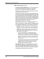
NOTE: Forms Description Language (FDL) commands cannot
be used on the DP EPS, because these systems do not have
forms compiling capability. You can, however, create forms by
using FDL on another laser printing system or by using a forms
creation software package on a PC or other type of workstation.
Form files that are created externally can be transferred or
imported to the system disk of your DP EPS, and can be
specified for jobs that are printed on the system.
Conventions
This guide uses the following conventions:
•
Alerts: Alerts include notes, cautions, and warnings.
– Notes are hints that help you perform a task or
understand the text.
– Cautions alert you to an action that could damage
hardware, software, or your print job.
– Warnings alert you to conditions that may cause injury to
people.
Alerts appear as follows:
– Notes: Printed in italics
– CAUTIONS: Printed in red
– WARNINGS: Printed in bold red
•
xxiv
Angle brackets: Angle brackets surrounding a word indicate
the word is the name of a key on the controller keyboard. Key
names start with a capital letter. (Example: Press <Enter>.)
Using LCDS Print Description Language
Introduction
•
Square brackets: Placed around words or phrases that are
names of buttons that you click or menu options that you
select on a screen, and names of fields and text boxes on
screens. (Example: In the [Folders] field, select [resources].
•
Bold type: Used for emphasis. It is also used for keywords
that introduce items in a list.
•
Entering: Within procedures, the two-step process of keying
in text and pressing <Enter>. (Example: Enter y in the box).
•
Fixed pitch font: Used to indicate text that you enter in a
text field on a window, such as examples of PDL commands.
It also indicates text that the system displays on the screen,
such as messages. Example:
LINE DATA=(1,132), FONTINDEX=133;
•
Italics: Indicate variables (types of items that vary from one
command to another), or the position of a specified argument
in the command syntax. (Example: IDEN SKIP = value).
Italics are also used for document titles and library names (for
example, Using LCDS Print Description Language).
Related publications
Using LCDS Print Description Language is part of the Xerox
DocuPrint 100/115/135/155/180, 75/90, and 75 MX publication
sets.
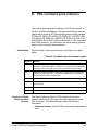
DocuPrint 100/115/135/155/180 EPS documentation
Following are related Xerox documents that pertain to the
DocuPrint 100/115/135/155/180 EPS.
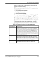
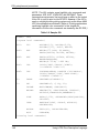
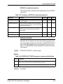
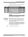
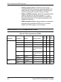
Table 1. DP 100/115/135/155/180 EPS documents
DocuPrint 100/115/135/155/180 EPS Customer Information Quick Reference Card
DocuPrint 100/115/135/155/180 EPS Font Reference Manual
DocuPrint 100/115/135/155/180 EPS Installation Planning Guide
DocuPrint 100/115/135/155/180 EPS Operator Guide
DocuPrint 100/115/135/155/180 EPS Operator Quick Reference Card
DocuPrint 100/115/135/155/180 EPS User Job Submission Quick Reference Card
DocuPrint EPS Tape Client Job Submission Guide
Using LCDS Print Description Language
xxv
Introduction
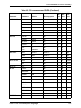
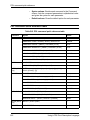
Table 1. DP 100/115/135/155/180 EPS documents (Continued)
DocuPrint EPS Using LCDS Print Description Language
DocuSP Common Controller System Guide
Getting Ready for the DocuSP Installation
Getting Started
Generic MICR Fundamentals Guide
Helpful Facts About Paper
MICR User Guide
NPS/IPS Extensions Operations Guide
Tape Formats Manual
Using the lp Utilities for Solaris
Using the lpr Utilities for DOS and Unix
Using the Xerox Client Software for Solaris
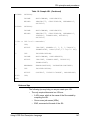
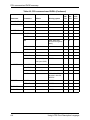
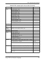
DocuPrint 75/90 EPS documentation
The following Xerox documents pertain to the DP 75/90 EPS and
the DP 75 MX.
Table 2. DP 75/90 EPS and 75 MX documents
DocuPrint 75/90 EPS Installation Planning Guide
DocuPrint 75/90 EPS Operator Guide
DocuPrint 75/90 EPS Operator Quick Reference Card
DocuPrint EPS Tape Client Job Submission Guide
DocuPrint EPS Using LCDS Print Description Language
Generic MICR Fundamentals Guide
DocuSP Common Controller System Guide
Getting Ready for the DocuSP Installation
Getting Started
Helpful Facts About Paper
MICR User Guide
Tape Formats Manual
Useful Resources
xxvi
Using LCDS Print Description Language
Introduction
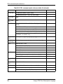
Table 2. DP 75/90 EPS and 75 MX documents
Using the lp Utilities for Solaris
Using the lpr Utilities for DOS and Unix
Using the Xerox Client Software for Solaris
Using LCDS Print Description Language
xxvii
Introduction
xxviii
Using LCDS Print Description Language
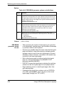
1.
PDL principles and procedures
The Xerox LCDS Print Description Language (PDL) is a set of
commands that you give to the printing system to define
properties such as the appearance, output destination, and
paper feed source for your LCDS print job.
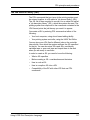
You can use LCDS PDL to do all of the following in your print
jobs:
•
Change and mix font types on a page to page, line to line, or
character to character basis. This allows you to customize
printed output for specific needs; for example, emphasizing
important headings by changing font styles and sizes.
•
Change text orientation and positioning on a page to page
basis. This allows you to print characters along the width or
length of the page with equal ease. The printing system can
switch instantly, at a page boundary, between portrait (tall
and narrow) and landscape (wide) page formats, combining
the two styles within a single report.
•
Print a number of previously separate logical pages on the
same physical page of a document.
•
Modify documents on a page to page basis by using copy
modification entries (CMEs) to replace selected portions of
text with other data, change fonts, or label copies as
“confidential.”
•
Merge variable print data with forms stored on the system
disk. This feature eliminates the need for forms overlays and
most preprinted forms, as well as assuring perfect
registration.
•
Print two different forms back to back (duplex) on one sheet
of paper, thereby reducing paper costs. Additionally, this
option offers potential savings in inventory, filing, storage, and
mailing costs for computer generated material.
•
Feed paper either short edge first or long edge first to
accommodate a variety of paper sizes.
Using LCDS Print Description Language
1-1
PDL principles and procedures
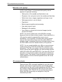
Enabling PDL features and functions
To enable these functions, you enter PDL commands that do the
following for your print job:
•
Describe the input (type, format, characteristics, and source)
•
Define any logical or special processing functions to be
performed on selected text, pages, or copies
•
Describe the output (type, format, font selection, accounting
options, and destination)
Each command has a set of parameters and parameter options
that are used to define the above characteristics of a print job.
PDL commands may be specified in the following ways:
Job Source
Libraries (JSLs)
•
In a Job Source Library (JSL)
•
As Dynamic Job Descriptor Entries (DJDEs)
One way to issue PDL job definition commands to your printing
system is to create a text file of these commands for your job.
The source (text, uncompiled) file of PDL commands is called a
“job source library” (JSL) file. The JSL file is then compiled by the
system to create an object file, called a “job descriptor library”
(JDL).
Each compiled JDL file is stored in a resource folder named
“lcds” that is located on the controller disk. The system accesses
the required JDL from the “lcds” folder when the operator
specifies it to start a job. When a job is sent from the host, the
printing system reads the specified JDL, from which it obtains
instructions on what fonts and forms to use when printing the job,
where to direct the printed output, and so forth.
Dynamic job
descriptor entries
(DJDEs)
Dynamic Job Descriptor Entries (DJDEs) are parameters
embedded within the input data stream. They modify the printing
environment established by a job descriptor entry (JDE) within a
JDL, as the job is printing. DJDEs allow page by page or record
by record modifications to your applications.
Most PDL commands are also available as DJDEs. (Refer to
“PDL command and DJDE summary” in appendix A for
information on which PDL commands have DJDE counterparts.)
In order to use DJDEs, you must specify an IDEN command in
the JSL to advise the system that DJDE records are included in
the input data stream and where to look for them.
1-2
Using LCDS Print Description Language
PDL principles and procedures
(Refer to “Specifying DJDE records,” later in this chapter for
information on how to include DJDEs in the data stream.)
PDL command structure and components
In order for the system to recognize and respond correctly to
your PDL commands, you must construct and enter them
correctly. Some components of PDL commands must be
specified every time, while others are optional. There are some
rules for constructing commands. You must follow these rules in
order for your system to print your job the way you want it. (Refer
to “Command syntax,” later in this chapter, for details on the JSL
syntax rules.)
Command lines
The JSL consists of command lines, also called records, on
which you enter PDL commands. The length of these records
can be up to 133 characters for JSLs on tape.
NOTE: If you select the [TRUNCATE] option of the xjdc
compiling command, only characters 1 through 72 may be used
for parameter information. Refer to “Compiling a JSL,” later in
this chapter.
You can continue commands on successive lines if the
parameters are separated by commas. Multiple commands may
appear on one record line if separated by semicolons.
Components of a command
Each PDL command consists of a command keyword and one or
more parameters. Parameters are separated by commas or
spaces. A PDL command has the following parts:
•
Command identifier (if required)
NOTE: DJDEs do not have identifiers.
•
Command keyword
•
One or more command parameters
•
Parameter options
•
Comments (if appropriate)
Using LCDS Print Description Language
1-3
PDL principles and procedures
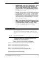
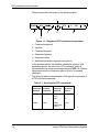
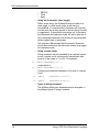
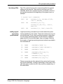
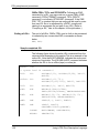
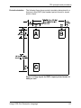
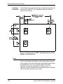
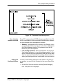
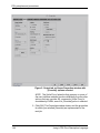
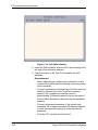
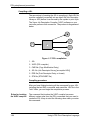
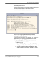
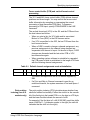
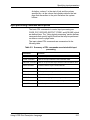
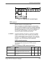
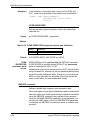
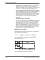
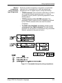
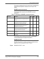
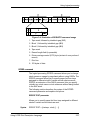
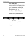
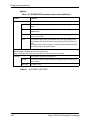
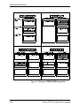
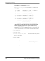
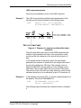
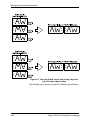
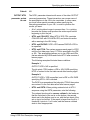
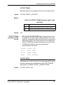
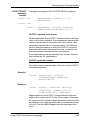
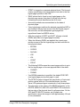
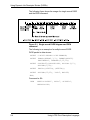
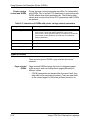
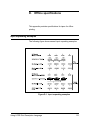
These components are shown in the following figure.
Figure 1-1. Diagram of PDL command components
1. Command statement
2. Identifier
3. Command keyword
4. Parameter keyword
5. Parameter option
6. Additional parameter keywords and options
In the example above, the identifier, parameter keyword, and
parameter options are part of the VFU command, which is
represented by the required command keyword VFU. All of these
components may be collectively referred to as a “command
statement.”
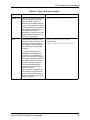
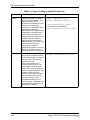
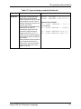
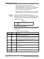
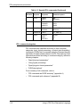
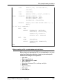
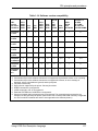
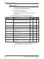
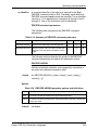
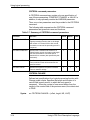
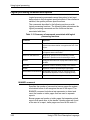
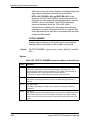
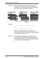
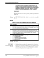
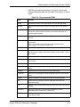
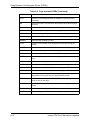
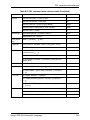
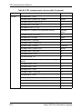
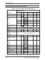
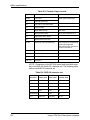
The following table shows examples of the typical components of
a PDL command statement.
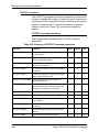
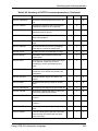
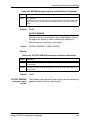
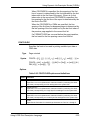
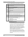
Table 1-1. Set of typical PDL commands
1-4
Command
identifier
Command
keyword
(required)
VFU1:
CME4:
Parameter
keywords
Parameter
options
VFU
ASSIGN=
TOF=
BOF=
(1,1),
1,
55;
CME
LINE=
POSITION=
FONT=
(1,60),
5,
2;
Using LCDS Print Description Language
PDL principles and procedures
Command
identifier
Some PDL commands require identifiers to precede their
command keywords. By coding an identifier before a command,
you associate the identifier with the command. This allows the
command to be referenced (by its identifier) by other commands
within the JSL. Some identifiers also determine the names of the
files that the XJDC compiler creates.
Different syntax rules apply to identifiers, depending on the
command being coded. Each command description in this
document tells you if an identifier is required (or optional) for the
command and if so, how it must be coded.
In most cases, in a JSL, if a command will be referenced by
another command within the JSL, an identifier must precede the
keyword of the referenced command. A command identifier is
defined using a label of up to six alphanumeric characters,
followed by a colon (:).
There are two types of identifiers that can be used:
1. ac type: Must have at least one alpha character (that is, a
letter).
2. dd type: May have all numerals, all alpha characters, or a
combination of both.
The following PDL command has the command identifier VFU1.
(Its keyword is VFU.)
VFU1: VFU
ASSIGN=(1,1), TOF=1, BOF=55;
END;
The identifier in this command may have any number of blanks
following the VFU1 characters; however, no blanks are permitted
within the identifier name.
NOTE: A command that requires an identifier must always be
defined before any other command that references it.
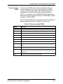
Command
keyword
Every command must have a keyword, which is the “name” of
the command for which various parameters may be selected.
In the following example, CME is the command keyword (CME4
is the identifier).
CME4: CME
LINE=(1,60), POSITION=5, FONT=2;
In the next example, the command keyword OUTPUT can be
followed by any number of parameters, such as:
OUTPUT GRAPHICS=YES, DUPLEX=NO, FORMAT=PDFLT,
FORM=BAR;
Using LCDS Print Description Language
1-5
PDL principles and procedures
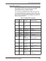
Refer to the “Summary table of PDL commands and DJDEs” in
appendix A for a list of all available command keywords.
Parameters
Parameter options
and right part
components
Each command keyword is followed by parameters. Parameters
give precise specifications for the print job or application.
•
In commands that comprise a JSL, each parameter consists
of a left part and a right part, separated by an equal (=) sign.
(Spaces before and after the equal sign are optional.) The left
part is the parameter name; the right part indicates the
parameter options or values.
•
In DJDEs, the left part is the DJDE command name. The
DJDE options are right part components, following the equal
sign.
The right part of a parameter contains the options, which may
consist of keywords, variable references, and value or string
constants.
Each parameter has one or more options. For example, the
OFFSET parameter of the OUTPUT command (which can be
shortened to OUTPUT OFFSET parameter) has three options:
ALL, FIRST, and NONE.
Some parameter options have multiple components. Some of
these components must have values specified; others are
optional. Parentheses are used to enclose multiple components
of a right part, as shown in the following example.
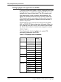
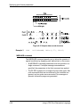
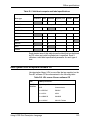
In the example below, the VFU command has three parameters:
ASSIGN, TOF (top of form), and BOF (bottom of form).
VFU1: VFU
ASSIGN=(1,1), TOF=1, BOF=55;
END;
In this example, the ASSIGN parameter option has two
components. Multiple components of an option must be coded in
the order shown in the command description syntax diagram.
•
Keywords
Keywords are terms that direct the system to perform specific
activities. Keywords always consist of the same characters
and do not vary.
1-6
Using LCDS Print Description Language
PDL principles and procedures
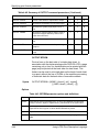
Example:
•
ABNORMAL
ERROR=CONTINUE, OTEXT=(... WAIT);
ACCT
USER=BOTH;
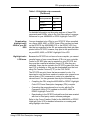
Variable references
In creating your JSLs, you will often include variable
references, which may be either file names of resources
stored on the system disk (forms, CMEs, PDEs, stocksets,
and so on); or they may be identifiers for commands that
were coded previously in the JSL.
Example:
OUTPUT
FORM=FORM1, MODIFY=CME12;
NOTE: In some cases, such as in the MODIFY= command
shown in the example above, the variable (CME12) could be
either a file name or an identifier for a CME coded earlier in
the JSL. In other cases, such as in the FORM= command,
the variable (FORM1) can only be a file name.
•
Value constants
Value constants have arithmetic values. Value constants
should be expressed as decimal numbers. They may also be
expressed as hexadecimal values, octal values, or character
values, but these expressions are not recommended.
Decimal numbers may be signed and may have fractional
digits.
Example:
PDE
BEGIN=(1.1,.37);
RECORD
LENGTH=132;
OUTPUT
IMAGE=(1.30 CM,0.85 IN);
To express value constants as hex, octal, or characters, you
use string constants to define one or two bytes of data.
•
String constants
String constants are used to specify a sequence of
characters. The length of string constants is important.
– Ways to express string constants
String constants may be expressed as any of the
following:
•
•
Hexadecimal
ASCII
Using LCDS Print Description Language
1-7
PDL principles and procedures
•
•
•
EBCDIC
Octal
Kanji
– Using the # character (case toggle)
Within a text string, the # character may be used as a
case toggle. In other words, when a text string is
encountered, it is assumed that characters are inserted
into the print line as they appear in the text string (usually
in uppercase). If the system encounters a #, it interprets
the characters as lowercase mode. All letters after the #
are considered lowercase until another # is encountered,
which toggles back to uppercase.
The sequence ## indicates that the actual # character
should be inserted and should not be treated as a toggle
for lowercase mode.
– Using a repeat count
String constants may be preceded by an optional repeat
count. A repeat count is enclosed in parentheses and
must be in the range of 1 to 255. For example:
T1: TABLE CONSTANT=(3)'*';
is equivalent to:
T1: TABLE CONSTANT=('***');
Following are additional examples of the use of a repeat
count:
T1: TABLE
CONSTANT=(3)O'27';
T2: TABLE
CONSTANT=(4)X'C1';
– Types of string constants:
The following table gives explanations and examples of
the different types of string constants.
1-8
Using LCDS Print Description Language
PDL principles and procedures
Table 1-2. Types of string constants
Constant
Definition
Example
Hexadecimal
Normally used as string constants,
but they may also be used as
value constants. Each pair of
hexadecimal characters results in
one byte. A hexadecimal constant
must immediately be preceded by
the characters X apostrophe (X’),
then followed by another
apostrophe, to indicate to the PDL
compiler that the expression that
follows is in hexadecimal.
IDEN PREFIX=X'C1C2C3C4';
ASCII
Used as string constants. Each
character results in one byte. The
constants must be preceded by
the characters A apostrophe (A’)
and followed by an apostrophe
character.
IDEN PREFIX=A'ABC!44EF'
is equivalent to
IDEN PREFIX=X'414243444546'
The ASCII string type allows
hexadecimal representation of
characters to be embedded in a
string. This is done by preceding
the hexadecimal representation of
the character with an ! character.
The three character sequence
required for the hexadecimal
representation of a character
results in one byte.
Two successive ! characters (!!)
are necessary to represent one
actual ! character when printing.
The two character sequence (!!)
results in one byte.
Using LCDS Print Description Language
1-9
PDL principles and procedures
Table 1-2. Types of string constants (Continued)
Constant
Definition
Example
EBCDIC
EBCDIC constants are used for
value and string constants. They
must be preceded by the
characters E apostrophe (E’) and
followed by an apostrophe
character (’). The EBCDIC string
type allows hexadecimal
representation of characters to be
embedded in a character string.
This is done by preceding the
hexadecimal representation of the
character with an ! character.
Each character represented in
EBCDIC results in one byte. Each
three character sequence
representing a character
hexadecimally results in one byte.
NOTE: If no character type is
specified, EBCDIC is the default.
IDEN
TABLE
Octal constants should be used
only as string constants because
of the control program conversion
process. Each octal character
results in three bits.
Each octal character pair is
converted internally to an 8 bit
octal character by prefixing two
binary zeros. Thus, the arithmetic
value of a multiple character octal
constant may be difficult to
determine, because each digit in
the constant has been altered.
An octal constant must be
preceded immediately by the
characters letter O apostrophe (O’)
and immediately followed by the
apostrophe (’) character.
RECORD
Octal
1-10
PREFIX='DJDE';
CONSTANT='ABCDE';
IDEN PREFIX=E'ABC!C4EFG'
is equivalent to the hexadecimal
IDEN PREFIX=X'C1C2C3C4C5C6C7’
CONSTANT=O'07070707'
Using LCDS Print Description Language
PDL principles and procedures
Table 1-2. Types of string constants (Continued)
Constant
Definition
Example
H2 and H6
H2 and H6 constants generate
H2000 BCD and H6000 BCD
codes, respectively. Use of H2 and
H6 is identical to use of E and A
prefixes described in the previous
sections of this table.
Since H2000 and H6000 BCD are
defined as 6-bit codes, no
specification greater than X’3F’
generates a legal character. If
anything from X’40’ to X’FF’ is
coded, an error message appears
and the bad character is replaced
with a blank.
String constants may be replaced
by an optional repeat count. A
repeat count must be enclosed in
parentheses and must be in the
range of 1 to 255.
BLOCK
BLOCK
Using LCDS Print Description Language
CONSTANT = H2’373737’;
CONSTANT = H6’373737’;
Repeat count examples:
T1: TABLE
CONSTANT = (3)’*’;
is equivalent to:
T1: TABLE CONSTANT = (‘###’);
T1: TABLE CONSTANT=(3)O’27’;
T2: TABLE CONSTANT=(4)X’C1’;
1-11
PDL principles and procedures
Command syntax
For the system to read and process any command you put in
your JSL, you must place all elements in the proper order and
use the correct symbol or amount of space to separate them.
Syntax rules
When you enter your PDL commands at the controller,
workstation, or host keyboard, you must follow these syntax
rules in order for the system to recognize the commands.
•
Abbreviations: Command and parameter keywords can be
shortened to the first three letters; for example, POSITION
may be entered as POS, OUTPUT as OUT, etc.
NOTE: The only exception to this abbreviation rule is the
parameter FOR, which the system could interpret as
FORMAT, or FORM, or FORMS. Therefore, be sure to use
the full spelling to represent FORMAT or FORM(S).
•
Blank spaces: You may use blanks anywhere in the JSL
except in keywords and constants.
•
Continuation lines: The DP EPS accept continuation lines
in DJDEs. The following is an example of a DJDE using a
continuation line.
NOTE: Use of continuation lines is not recommended
because the results are unpredictable
Incorrect structure for DP EPS:
DJDE FONTS=(fn1,fn2,fn3,...,fn13,
DJDE fn14,fn15,fn16);
Valid structure for DP EPS:
DJDE FONTS=(fn1,fn2,fn3,...,fn13),;
DJDE FONTS=(fn14,fn15,fn16),;
•
End of a command: Place a semicolon (;) at the end of
every PDL command.
•
End of a JSL: Use the END; command to signal the end of a
JSL or other file such as a PDE, CME, or STOCKSET.
•
End of all JSLs: To signal the end of all JSLs, PDEs, CMEs,
TSTs, or STOCKSETS that are being processed, enter END
followed by a semicolon (;) twice, as shown below.
END; END;
1-12
Using LCDS Print Description Language
PDL principles and procedures
•
Multiple part options: Use parentheses to enclose multiple
parts of a parameter option.
Example:
CRITERIA CONSTANT=(0,120,EQ,T1);
•
Order of right part components: If you want to specify
more than one component of a parameter right part, enter the
components in the order they are shown in the command
description and separated by commas.
Example: The MESSAGE OTEXT parameter has two
alternative options, one of which has four components
enclosed in parentheses. (The square brackets indicate that
a component is optional. The braces indicate that the
command contains alternative options, only one of which may
be used. Alternatives are separated by the “|” separator
character.)
OTEXT={(sc [,{passnum|END}][,WAIT])|NONE}
•
Placeholders: To specify a particular component but not the
optional components preceding it, do not enter more than
one comma as a “place holders” for the component you do
not specify. The component must be optional as indicated by
square brackets in the syntax definition for the parameter.
When the comma preceding the optional component appears
inside the square brackets, then it is provided only if the
component is provided.
Example: If you want to specify an operator message
(OTEXT) and the WAIT parameter, but wish to use the
default value for passnum, enter:
OTEXT=(‘load blue paper’, WAIT);
The passnum component is not supplied in the example, and
its default value is used instead.
•
Singular or plural: You may use either the singular or plural
form of the FONT, FORM, and GRAPHIC parameters. (The S
in FONTS, FORMS, and GRAPHICS is optional.)
•
Separation of parameters: Use commas and blanks to
separate parameters within a command.
Example:
BANNER
TEST=C1, HCOUNT=1, TCOUNT=2;
Using LCDS Print Description Language
1-13
PDL principles and procedures
NOTE: Commas and blanks cannot be used
interchangeably. Many commands require commas to
separate the parameters, and blanks are not valid delimiters.
The syntax diagram in each command and parameter
description shows which delimiters to use.
•
Command
example
Uppercase text: Use UPPERCASE letters when coding PDL
commands. Comments, however, need not be in uppercase.
The following LINE command example contains three
parameters. The right part of the VFU parameter is a reference
to an identifier “VFU1.” The right part of the DATA parameter has
two components that are value constants, and OVERPRINT
uses keyword constants.
Table 1-3.
LINE
VFU=VFU1, DATA=(1,10),
OVERPRINT=(PRINT,DISP);
Command syntax conventions
The command descriptions use the syntax conventions shown in
the table below.
Table 1-4. Syntax conventions
1-14
Symbol
Term
Function
( )
Parentheses
Enclose options in a command right part that consist of two or more
components, separated by commas.
{ }
Braces
Enclose a set of choices for a right part component, or the entire right
part of a command for which there are two or more alternative
(“either–or”) options, only one of which must be selected.
|
Separator
Separates alternative command right part options, one of which must
be selected. (Means “or.”)
[ ]
Square
brackets
Enclose components that are optional and not required for the
command.
,
Comma
Separates multiple parameters or components of a parameter right
part (means “and”).
OUTPUT
(example)
Uppercase
letters
Denote a keyword for a command, parameter, or option.
value
(example)
Italics
Denote a variable you must define.
Using LCDS Print Description Language
PDL principles and procedures
Sample PDL commands
The following table lists a set of commands in the order that they
might appear in a JSL. It shows the components of PDL
commands and a variety of right part options.
The commands are displayed below in table form so you can
more easily distinguish their components. When coding a JSL,
you may want to use tabs to separate these parts. You may also
prefer to place all parameters for a command on the same line
with the command keyword.
Table 1-5. Sample PDL commands
Identifier
Command
keyword
Parameter
keywords
Parameter options
VFU1:
VFU
ASSIGN=
TOF=
BOF=
(1, 1),
1,
55;
VFU2:
VFU
ASSIGN=
TOF=
BOF=
(1, (4, 59)),
4,
127;
T1:
TABLE
CONSTANT=
('CLIPS');
C1:
CRITERIA
CONSTANT=
LINENUM=
(14, 5, EQ, T1),
(6, 3);
T2:
TABLE
CONSTANT=
('1');
C2:
CRITERIA
CONSTANT=
(0, 1, NE, T2);
CME1:
CME
LINE=
POS=
CONSTANT=
3,
59,
'FIRST QUARTER';
CME4:
CME
LINE=
POSITION=
FONT=
(1, 60),
5,
2;
PDE2:
PDE
PMODE=
BEGIN=
FONTS=
PORTRAIT,
(1.1,.37),
(P08TYA, P08SCA);
CODTAB:
CODE
DEFAULT=
ASSIGN=
EBCDIC,
(X'4A', X'B4');
RECORD
STRUCTURE=
LENGTH=
FB,
132;
LINE
VFU=
DATA=
OVERPRINT=
VFU1,
(1, 10),
(PRINT, DISP);
Using LCDS Print Description Language
1-15
PDL principles and procedures
Table 1-5. Sample PDL commands (Continued)
Identifier
Command
keyword
Parameter
keywords
Parameter options
ACCT
USER=
DEPT=
BIN,
'MEDCAR';
OUTPUT
FORMS=
FORMAT=
MODIFY=
XER111,
PDE2,
CME4;
ROUTE
RTEXT=
RFORM=
('ENGINEERING', 2, 56, 109),
XERCOV;
RDELETE
TEST=
(C1, AND, C2);
IDEN
PREFIX=
SKIP=
OFFSET=
‘$DJDE',
10,
1;
PDL command categories
PDL commands are classified according to their functional
categories: input, logical processing, or output (print formatting)
commands. DJDEs are in a separate category, because they are
specified in the data stream instead of a JSL. Descriptions of the
commands are listed according to command category, within the
following chapters:
•
“Specifying input parameters”
•
“Using logical processing”
•
“Specifying print format parameters”
•
“DJDE descriptions”
For a summary of all commands, refer to:
1-16
•
“PDL command and DJDE summary” (appendix A)
•
“PDL command quick reference” (appendix B)
Using LCDS Print Description Language
PDL principles and procedures
The Job Source Library (JSL)
The PDL commands that you issue to the printing system must
be entered together in a file called a “job source library” (JSL).
The JSL file is then compiled to convert it to an object file called
a “job descriptor library” (JDL), which the system can read. The
printing system then responds to the commands contained in the
JDL file and prints the job the way you want it to appear.
You create a JSL by entering PDL commands at either of the
following:
•
Your host computer, using a host based editing facility
•
Your printing system controller, using the UNIX Text Editor
You can store your JDL files for different jobs on the controller
internal disk, from which the system retrieves the JDL specified
for the job. You can also store JDLs and JSLs on diskette,
cartridge tape, or open reel tape and import them to the disk
when you are ready to use them.
In order to create a JSL you need to know the following:
•
What a JSL specifies
•
Before creating a JSL: considerations and decisions
•
How to code a JSL
•
How to compile a JSL into a JDL
•
Compatibility of the DP with other LPS that use PDL
commands
Using LCDS Print Description Language
1-17
PDL principles and procedures
What does a JSL specify?
A JSL is a set (“library”) of commands that specify various
aspects of a print job, including:
•
What portion of the variable and fixed data to use
•
Placement, font, and point size for the variable and fixed data
•
Which fonts, forms, images, signatures, and logos to use
•
What paper stocks to use for the job
•
Page layout
•
Banner page recognition and processing
•
How many copies to print
•
Messages to the operator
•
Use of black or colored ink for text and images (see the
second note below).
NOTE: You cannot create forms at the DP EPS controller,
because it does not have a forms compiler. Forms specified in a
JSL must be created as separate files at your host, a
workstation, or the controller of another laser printing system.
You can then import these forms onto the system disk from
diskette or tape, or download them from your host system using
the FILE DJDE or the File Transfer Protocol (FTP) process.
NOTE: You can create highlight color JSLs on a monochrome
system using many of the color related PDL commands and
parameters. The JSLs you create on the monochrome system
can be used on the Xerox highlight color laser printing systems
(4850 LPS, 4890 LPS, and DP92 LPS). If you use color JSLs to
print jobs on monochrome systems, the jobs print in black and
shades of gray. (The shades of gray that appear on the printed
output depend on the inks that are specified in the JSL for the
colored areas.)
JSL command levels
There are many PDL commands available for your job source
libraries, many ways of organizing them, and virtually infinite
combinations you can use to create applications with PDL. There
are, however, a few programming rules that you must follow
when creating a JSL. If the JSL is not structured according to
these rules, the system may not recognize or obey the
commands you enter.
1-18
Using LCDS Print Description Language
PDL principles and procedures
(Refer to “Coding a JSL” in this chapter for the procedure for
creating a Job Source Library.)
PDL commands are organized within a JSL in groupings called
“command levels.”
•
JDL or system level commands
•
Catalog level commands
•
Job or JDE level commands
You may code commands within these levels following the JDL
command, which identifies the start of the system level. The
system level must have at least the SYSTEM or JDL command.
The catalog level is not required, and there must be at least one
job specified in the JOB level. Some JSLs define only one print
job, but it is more common to find JSLs that define multiple jobs.
The following table outlines the command levels and some
typical specifications that are included in these various levels.
Table 1-6. Command levels and their general purpose
Command level
General purpose
JDL or system level
Establishes installation defaults.Commands at this level apply by
default to all jobs (JDEs) within the JSL. Command specifications
found in a job level, override specifications made at the system level.
NOTE: Some of these commands require an identifier, by which
other commands in the JSL can reference them. Commands with
identifiers are usually coded first; for example, the CODE and PCC
commands. Commands within this level with identifiers, apply to all
jobs and catalogs within the JSL.
Catalog level
Groups PDL commands for easy reference at the job level. Catalog
command sets are defined before the JOB or JDE command that
references them. The catalog command sets are usually all defined
before the first JDE or JOB command; therefore, they are considered
to be coded at a separate level, called the “Catalog level.”
Job or JDE level
Defines how individual print jobs are processed. JDE level
commands apply only to the job under which they are listed.
Using LCDS Print Description Language
1-19
PDL principles and procedures
The following table illustrates a sample JSL file format and
provides examples. Note that comments are used to designate
the beginning of each level.
Table 1-7. Sample JSL file format
/* This sample JSL shows the JSL command levels*/
JDLSMP:
JDL;
/* System level commands coded here*/
VFU1:
VFU
ASSIGN=(1,1), TOF=1, BOF=66;
VFU9:
VFU
ASSIGN=(1,9), TOF=9, BOF=66;
VOLUME
HOST=IBMOS;
RECORD
LENGTH=133;
LINE
VFU=VFU9, DATA=(1,132);
OUTPUT
FORMS=CPPR1, DUPLEX=NO, COPIES=2;
/* Catalog commands coded here if needed*/
CAT1:
CATALOG;
LINE
VFU=VFU1;
OUTPUT
FORMS=FORM2
/* Job level commands coded here*/
JOBCPP:
JOB;
JOB2:
JOB
INCLUDE=CAT1;
JOB3:
JOB
INCLUDE=CAT1;
OUTPUT
DUPLEX=YES
END;
1-20
Using LCDS Print Description Language
PDL principles and procedures
JDL name
Begin your JSL by deciding on a name for the compiled JDL and
entering the “JDL” command on the first line of the JSL. The
JDLNAME is a 1 to 6 character alphanumeric identifier
specifying the name of the JDL to be created.
Select a name that is related to the function of the JDL and
identifies the type of jobs you are creating. For example, if your
site has several input sources, you might want to name the JDL
for an online job “JDLONL: JDL;.”
The format for naming a JDL is:
JDLNAME: JDL;
For example, you might name a JDL containing short edge feed
(large paper size) jobs:
JDLSEF: JDL;
When a JSL is coded, the word SYSTEM is sometimes used in
place of JDL. The meaning is exactly the same. In the following
example, the JDL name SAMPL corresponds to the name of the
JDL to be used when printing a job. The command can be stated
in the following ways:
SAMPL: SYSTEM;
SAMPL: JDL;
JDL or system level commands
PDL commands coded at the JDL or system level establish
default print job characteristics. Commands that are common to
all the jobs in the JSL are listed at this level so that they need not
be coded in every job in the JSL. System level commands,
however, may be overridden by commands at the job or JDE
level.
NOTE: The JDL level is the highest level in a JSL. When you
enter the following command levels, you may wish to indent
them under the system level commands.
Coding system level commands with identifiers
System level commands that require identifiers are typically
coded first. These commands must be placed in the JSL either
before or in the same job as any other commands within the
library that reference their identifiers. The identifier that begins
the command is typically placed at the left margin (at the
beginning of the line).
Using LCDS Print Description Language
1-21
PDL principles and procedures
The VFU (vertical format unit) commands in the JSL illustration
shown in table 1-7 are examples of commands with identifiers.
(In this JSL, the VFU command identifiers are called “VFU1” and
“VFU9.”)
The types of commands described in the following sections are
usually coded first at the system level (following the JDL
command) because:
•
They require identifiers.
•
They typically apply to all jobs within a JSL.
These commands include:
•
VFU commands
•
TABLE commands
•
CRITERIA commands
•
PDE commands
•
CME commands
•
CODE commands
•
VOLUME commands
•
RECORD commands
•
BLOCK commands
NOTE: Make sure that the first command line of the JSL is the
JDL identifier command. The system level ID commands then
follow. For example:
XSML: JDL;
VFU1: VFU ASSIGN=(1,1), TOF=1, BOF=66;
“XSML” is the name of the complete JDL. The VFU command is
at the system level and has the identifier “VFU1.”
1-22
Using LCDS Print Description Language
PDL principles and procedures
Specifying VFUs
The VFU (vertical format unit) command specifies the vertical
tabbing for the print job. There can be more than one VFU
identified. Each VFU command requires an identifier. All VFUs
are typically specified at the beginning of the system level; for
example:
/* System level commands*/
Adding logical
processing
specifications
VFU1:
VFU
ASSIGN=(1,11), ASSIGN=(12,66),
TOF=11, BOF=66;
VFU2:
VFU
ASSIGN=(1,(11,77)),
ASSIGN=(12,(66,132)), TOF=11,
BOF=132;
VFU3:
VFU
ASSIGN=(1,1), TOF=1, BOF=132;
Logical processing commands are invoked when the system
locates satisfactory test criteria. These test criteria are set up for
record fields and, if met, allow special processing to take place
for such things as banner pages, record selection or deletion,
page selection from auxiliary paper trays, and page offsetting.
An example of logical processing tests and criteria is provided in
this command set:
T1:
TABLE
CONSTANT=('PAGE 1');
T2:
TABLE
CONSTANT=('INPUT RECORDS');
T3
TABLE
CONSTANT=('JOB');
C1:
TABLE
CONSTANT=(122,6,EQ,T1),
LINENUM=(1,10);
C2:
TABLE
CONSTANT=(14,13,EQ,T2);
C3:
TABLE
CONSTANT=(14,3,EQ,T3);
These commands are often placed at the system level because
they require identifiers. However, depending on how many of the
jobs they apply to within the JSL, they could be coded at any of
the other levels.
Using LCDS Print Description Language
1-23
PDL principles and procedures
Specifying formats
(PDEs)
Using copy
modification
entries
Defining character
code translation
tables
There are many standard formats or print description entries
(PDEs) available for your JSL. These formats are listed in the
“PDE command” section of the “Specifying print format
parameters” chapter. PDEs, like VFUs, require identification; for
example:
PDE1:
PDE
BEGIN=(0.18IN,0.66IN),
FONT=(L0112B,L01BOA),
PMODE=LANDSCAPE;
PDE2:
PDE
BEGIN=(1.03,.51),
BEGIN=(6.30,.51),
FONTS=P1012A, PMODE=PORTRAIT;
Copy modification entries (CMEs) allow you to change certain
parts of static data in report output and to change fonts within
variable data. Below are some sample CMEs:
CME1:
CME
LINE=(9,–), POS=1, FONT=1;
CME2:
CME
LINE=3, POS=59,
CONSTANT='FIRST QUARTER’;
CODE commands define character translation tables used to
convert input job data into printed characters. For example:
C1:
CODE
DEFAULT= EBCDIC;
ASSIGN= (’\’, ’/’);
Coding other system level commands
System level commands without identifiers should be indented
under the commands with identifiers. One exception is the JDL
name command, which precedes the identifier commands and is
not indented.
The following sections discuss several other commands that are
usually coded at system level and that do not require identifiers.
1-24
Using LCDS Print Description Language
PDL principles and procedures
Setting up input
parameters
You may want to start by specifying the input data characteristics
for the application. The basic input processing commands are
BLOCK, CODE, PCC, RECORD, TCODE, and VOLUME. Input
processing characteristics vary depending on the data source.
For example, if your JSL is for an online application, the BLOCK
command is not applicable. Also, parameters within a command
may apply to offline only, online only, or both. For example, with
the VOLUME command, the parameters CODE and HOST can
apply to both online and offline; EOV applies only to offline
applications; and OPTIMIZE applies only to online applications.
Following are examples of typical input processing commands.
•
•
Specifying LINE
command
parameters
Online:
VOLUME
HOST=IBMONL, CODE=EBCDIC;
RECORD
LENGTH=136;
Offline:
VOLUME
HOST=IBMOS,LABEL=STANDARD,CODE=EBCDIC;
BLOCK
LENGTH=2660, PREAMBLE=4, LTHFLD=2,
FORMAT=BIN;
RECORD
LENGTH=135, PREAMBLE=4, LTHFLD=2,
STRUCTURE=VB, OFFSET=2, FORMAT=BIN;
The LINE command references VFUs from the system level and
allows you to instruct the system on which parts of the data in
each record will be printed. For this reason, it typically follows the
RECORD command. For example:
LINE
Specifying ACCT
command
parameters
DATA=(1,132), PCCTYPE=IBM3211,
PCC=(0,NOTRAN), VFU=VFU1;
The ACCT command often follows the LINE command and can
be coded into any command level.
ACCT USER=TRAY;
Using LCDS Print Description Language
1-25
PDL principles and procedures
Catalog level commands
The catalog level allows the coding of commands common to
several JDEs. A catalog can then be referenced in an INCLUDE
parameter in any following JDE commands. A catalog section of
a JSL begins with the CATALOG command and ends with the
appearance of another CATALOG command or a JOB
command. CATALOG commands may contain the same
commands that appear in the JOB command.
The CATALOG command has the form:
catname: CATALOG;
The CATNAME is a 1 to 6 character alphanumeric identifier, of
which at least one character must be alphabetic. The catalog
name is referenced by JDEs after the CATALOG command set
has been defined.
For example:
POWER: CATALOG;
In this command, POWER is the catalog level identifier to be
used in the INCLUDE parameter of a JOB command. To
reference the catalog named POWER in a job, the job level
command would be:
JOB1: JDE
INCLUDE=POWER;
Job or JDE level commands
A JSL contains one or more elements called “jobs” or “Job
Descriptor Entries.” A JDE, along with its system level
commands, describes the options that apply to one printing task.
A JDE contains one input format, one set of processing
instructions, and one set of output instructions. The identifier for
each JDE (job) is a user defined name that you invoke to run the
job.
PDL commands that are coded within the job command level
override the system commands. For each job, values not
specified in any of the command sets are taken from the PDL
defaults. (Refer to the “PDL command and DJDE summary”
table in appendix A for a list of all command defaults.)
PDL commands coded at a catalog command level can be
incorporated as shown in the command syntax below.
CATNAME is a 1 to 6 character alphanumeric identifier of a
previously defined catalog name.
1-26
Using LCDS Print Description Language
PDL principles and procedures
Examples of JOB
commands
Following are some examples of job commands.
JOB2:
JDE;
JOB3:
JDE
JOB4:
JDE;
INCLUDE=CAT2;
LINE
VFU=VFU2;
OUTPUT
FORMS=AY2F;
A JOB or JDE command remains in effect until another JOB or
JDE command or an END command is encountered. The
identifier in a JOB or JDE command, as in JOB2, JOB3, or JOB4
in the previous example, is used with the identifier on the JDL or
SYSTEM command to initiate a print job.
Coding job or JDE level commands
The commands discussed in this section are usually coded at
the JOB or JDE level of the JSL, because they normally vary by
individual job. However, you may want to code them at the
catalog level if you have grouped jobs together that have the
same characteristics as defined in the commands.
Defining stock
requirements
There are several ways to specify paper stocks with PDL. One
method is the STOCKSET command, which can be referenced
in lower level commands. Each formatted page is then
associated with the active STOCKSET command and the active
OUTPUT FEED parameter. If no FEED parameter is specified,
the INIFEED parameter of the STOCKSET command takes
effect.
•
Use the OUTPUT command and the PAPERSIZE and
SYSPPR parameters to specify physical and system paper
size. The OSTK and TRANS parameters allow you to specify
tab or transparency stocks, and the NTO1 parameter enables
you to instruct the printer to print the last page of a report first.
•
The FEED parameter of the OUTPUT command can either
specify a stock reference assigned in the STOCKSET
command or bypass this referencing and specify a stock
name called out in the current STOCKSET.
•
The INIFEED parameter of the STOCKSET command is the
default if no OUTPUT FEED parameter is present.
Using LCDS Print Description Language
1-27
PDL principles and procedures
Here is a sample STOCKSET command:
SSML:
Specifying output
requirements
STOCKSET
ASSIGN=('WHITE',CVR),
ASSIGN=('YELLOW',BLL),
ASSIGN=('GREEN',SUM),
INIFEED=CVR,
SYSPAGE=SUM;
There are many specifications you can select to define the
manner and look of your printed application. You can also have
messages displayed to operators to advise them of special
circumstances. This is done with the MESSAGE command:
MESSAGE OTEXT= ('ALL FORMS DUPLEX ONLY!!!', 1, WAIT);
NOTE: The MESSAGE OTEXT command shown above is one
example, and is not necessarily the recommended method for
switching media. (Refer to the OUTPUT STOCKS and OUTPUT
FEED command descriptions in the “Specifying print format
parameters” chapter, for further information.)
Similarly, the ROUTE command sends printed information
preceding the report to operators. Most output specifications are
selected from parameters of the OUTPUT command. As with
other commands, these can be specified at any command level,
but are most often specified at the job level because of the many
variations possible.
Job level
command
examples
Here are some examples of commands that are coded at the job
or JDE level:
/* Job level commands*/
JOB1:
JDE;
OUTPUT
JOB2:
1-28
DUPLEX=YES, SHIFT=YES,
FORM=SMPLE, MODIFY=CME1,
FORMAT=PDE1, COPIES=10,
BFORM=SMLBK, OFFSET=FIRST,
PURGE=NO;
JDE;
LINE
VFU=VFU2UP;
OUTPUT
FORMAT=PDE4, FORMS=SPL2,
COPIES=7;
Using LCDS Print Description Language
PDL principles and procedures
Comments
Comments are optional statements you may include in the
source file to identify sections of the JSL, describe selected PDL
commands and their functions, or provide messages for anyone
who modifies the JSL later. The system does not perceive these
comments as commands and ignores them.
Comments may appear anywhere within the JSL and may
consist of multiple records. Comments must be preceded by the
character sequence slash asterisk (/*), and terminated by the
character sequence asterisk slash (*/). For example:
/*System commands are coded here.*/
Nested comments
A comment may also be nested within another comment. There
is no practical limit to the level of nesting possible, as long as
each nested comment is preceded by a slash and an asterisk (/*)
and succeeded by an asterisk and a slash (*/). An acceptable
nested comment format is as follows:
/*
comment
/*
nested comment
*/
*/
Note that the illustration above ends with two */ markers: the first
for the nested comment and the second for the main comment.
Ending a JSL
A JSL terminates with the END command. When you are
finished constructing your JSL, you must let the system know
you are finished by entering the END; command, as shown
below. This also applies to CMEs, PDEs, TSTs, and
STOCKSETs you are coding.
END;
What may follow
the END;
command
After you end a JSL, you may still code certain items following
the END; command.
Subsequent JSLs: Following the END; command for one JSL,
you may code additional JSLs. If one JSL is to follow another,
the next command after the END; command should be another
“JDL” command.
Using LCDS Print Description Language
1-29
PDL principles and procedures
CMEs, PDEs, TSTs, and STOCKSETs: Following an END;
command for a JSL, you may code one or more CMEs (CME
command), PDEs (FORMAT command), TSTs (ROUTE
command), or stocksets (STOCKSET command). If the CME,
PDE, TST, or stockset that you are coding will be used by more
than one JSL file or is referenced by a DJDE, compile and
catalog it as a separate file (not part of any JSL). (Refer to
“Compiling a JSL,” later in this chapter, for the procedure.)
Ending all JSLs
The end of all JSLs, CMEs, PDEs, and so forth to be processed
is indicated by two consecutive END; commands as shown
below.
END; END;
Sample completed JSL
The following figure shows the entire JSL constructed from the
command level examples in this section.This is an example of an
online JSL. Note that HOST=IBMONL indicates the source and
structure of input data. The VOLUME=HOST command indicates
whether the JSL is for an offline (tape) or online job.
XRXSPL: JDL;
/* System level ID commands*/
VFU1:
1-30
VFU
ASSIGN=(1,11), ASSIGN=(12,66), TOF=11,
BOF=66;
VFU2UP: VFU
ASSIGN=(1,(11,77)),
ASSIGN=(12,(66,132)), TOF=11, BOF=132;
VFU3:
VFU
ASSIGN=(1,1), TOF=1, BOF=132;
PDE1:
PDE
BEGIN=(0.18IN,0.66IN),
FONT=(L0112B,L01BOA), PMODE=LANDSCAPE;
PDE2:
PDE
BEGIN=(1.03,.51), BEGIN=(6.30,.51),
FONTS=P1012A, PMODE=PORTRAIT;
CME1:
CME
LINE=(9,–), POS=1, FONT=1;
CME2:
CME
LINE=3, POS=59,
CONSTANT='FIRST QUARTER';
VOLUME
HOST=IBMONL, CODE=EBCDIC;
RECORD
LENGTH=136;
Using LCDS Print Description Language
PDL principles and procedures
SSML:
LINE
DATA=(1,132), PCCTYPE=IBM3211,
VFU=VFU1;
ACCT
USER=TRAY;
IDEN
PREFIX='C9700', SKIP=7, OFFSET=1;
STOCKSET
ASSIGN=('WHITE', CVR),
ASSIGN=('YELLOW', BLL),
ASSIGN=('GREEN', SUM),
INIFEED=CVR, SYSPAGE=SUM;
MESSAGE
OTEXT=('ALL FORMS DUPLEX ONLY!!!', 1,
WAIT);
/* Job level commands*/
JOB1:
JDE;
OUTPUT
JOB2:
DUPLEX=YES, SHIFT=YES,
FORM=SMPLE, MODIFY=CME1,
FORMAT=PDE1,COPIES=10,
OFFSET=FIRST, PURGE=NO;
JDE;
LINE
VFU=VFU2UP;
OUTPUT
FORMAT=PDE2, FORMS=SPL2,
COPIES=7;
END;
Before creating a JSL: considerations and decisions
Before starting to develop the JSL for your application, you must
make the following key decisions, based on your site specific
needs and the design of the application.
•
•
•
•
•
•
•
•
•
Input data
Output specifications
Type of application to create
Special features
Interactions between JSLs, catalogs, and jobs
Stock size
Page orientation
Font types
Hints and tips
Using LCDS Print Description Language
1-31
PDL principles and procedures
Input data
Before starting to develop the JSL for your application, you
should know the following information about the input data.
•
The input source, such as:
– The host that supports the 3211 or 4245 host interface
– Open reel or cartridge tape, which are offline devices
– System disk
– Combination of two or more of these sources
•
Computer on which the data was created
•
Block and record lengths and structure
•
Code in which the data is encoded, such as ASCII and
EBCDIC
•
How printer carriage control (PCC) information should be
processed
•
For tapes: the label format used
Output specifications
Before starting to develop the JSL for your application, you must
know the following about the printed output.
•
Will you modify an existing JSL or create a new one?
•
Will the orientation be landscape (horizontal) or portrait
(vertical)? (Refer to “Page orientation,” later in this chapter,
for an explanation of these terms.)
•
Will you use more than one type or color of stock in the print
job?
•
What fonts will be used?
•
Will you use a form? If so, you need to specify the form in
your JSL. If do not have an existing form that you can use,
you will need to create it and load it onto the system disk.
You may specify the first form for your job in the Queue
Manager, LCDS Setup, Output, or On-line Job Manager
windows on the controller, when you are ready to print. This
form selection overrides any initial form specified in the JSL.
(If you do not specify an Initial Form at the user interface, the
form defined in the JSL is used.)
•
1-32
What paper sizes will be used?
Using LCDS Print Description Language
PDL principles and procedures
•
Will copy modification entries (CMEs) be used?
•
Will the output be delivered face up, N to 1 (last page first),
and collated?
•
Will the data be printed on one side of the page (simplex) or
on both sides (duplex)?
•
Will graphics be used?
•
What types of applications will be printed? For example:
– Forms
– Reports
– Letters
– Billing statements using variable data, that is, information
that varies from customer to customer.
•
What are the conventions at your site, if any, for naming
forms, JSLs, files, and jobs?
This information helps you plan your application: the type of input
data to specify, the type of application to design, and how to
customize the application so that it meets its intended purpose
rather than using system defaults.
Special features
Before starting to develop the JSL for your application, determine
the following:
•
Will you display operator information, such as messages, on
the controller screen?
•
Will you select paper trays?
•
What will the page layout be? For example, a large form may
require an entire page but, if smaller formats are usable, you
may want to print two, or even four logical pages on each
physical page.
•
Will you use dynamic job descriptor entries (DJDEs) to
change the application on a page or report basis? (Refer to
the “Using dynamic job descriptor entries (DJDEs)” chapter
for an explanation of DJDEs and their coding process.)
Using LCDS Print Description Language
1-33
PDL principles and procedures
Interactions between JSLs, catalogs, and jobs
Before starting to develop the JSL for your application, consider
the interactions, similarities, and differences between various
JSLs, catalogs, and jobs. Remember: although a printing system
can have only one JOB or JDE in effect at a time, you can still
create JSLs with multiple JOBs or JDEs, and switch between the
JDEs by using DJDEs in the data stream.
•
What characteristics are used globally, if any, for all of the
applications at your site? For example, do all jobs use the
same host, format, paper size, page orientation, block or
record length, test criteria, DJDEs, error responses,
accounting requirements, fonts, or forms?
•
What names will you call the JSL and catalogs or individual
jobs within the JSL? Use names that will be meaningful to
you and others who may use the application.
Paper sizes and page frames
The printing system considers paper sizes in terms of page
frames, which are boundaries associated with a page as a unit of
printing or imaging. The system defines three page frames:
•
Physical page
•
System page
•
Logical page
In addition to paper size, you must consider edgemarking and
non-imaged elements when you design the pages of your
applications.
System page
The “system page” is the maximum image area of the printer for
the paper size. The system page size varies, depending on the
size of the paper for your job.
Physical page
The “physical page” is the size of the paper itself. You may select
any page dimensions within an 8 by 10 inch / 203 by 254 mm
minimum and a 14.33 by 17 inch / 364 by 432 mm maximum.
If your system is configured with the small paper kit option, your
minimum page size is 7 by 10 inches or 178 by 254 mm.
1-34
Using LCDS Print Description Language
PDL principles and procedures
Logical page
A “logical page” is a user defined page image that is bordered by
Top of Form and Bottom of Form and left and right margin
specifications. Up to 63 logical pages can be defined on a
physical page.
NOTE: You are not able to specify right margins on logical
pages. The right margin size is determined by the left margin and
the line length.
Edgemarking
“Edgemarking” occurs when text or graphics are printed outside
the physical sheet, giving the appearance of printing on the edge
of the paper. (Refer to the OUTPUT OSTK command description
in the “Specifying print format parameters” chapter, for more
information on edgemarking.)
NOTE: Edgemarks must start within the system page, although
they may print mostly outside the page boundaries.
Elements that do
not print
Elements of a page, that is, text and graphics, may begin at the
edge of the physical page and may even extend off the page.
However, if any part of a printed element begins off the system
page, then no part of the element is imaged.
•
If a line of variable data begins off the system page, no part of
the line is printed.
•
A ruled line must originate inside the system page in order for
the line to print.
•
If a ruled line begins off the system page, no part of the line is
printed.
Orientation
There are two types of text orientation on a page:
•
Portrait
•
Landscape
The vertical and horizontal positions for each of these
orientations are shown in the following figures.
Using LCDS Print Description Language
1-35
PDL principles and procedures
Figure 1-2. Vertical and horizontal positions
in portrait mode
1. Left margin (horizontal position or hpos)
2. Character cell
3. Top margin (vertical position or vpos)
Figure 1-3. Horizontal and vertical positions in landscape
mode
1. Left margin (hpos)
2. Character cell
3. Top margin (vpos)
1-36
Using LCDS Print Description Language
PDL principles and procedures
Portrait orientation
The following figure shows portrait orientation dimensions for a
document using FMT6 (the standard portrait format for impact
printer output).
Figure 1-4. Page layout for FMT6: Impact printer format, 8.1
lines per inch
Using LCDS Print Description Language
1-37
PDL principles and procedures
Landscape
orientation
The following figure shows landscape orientation dimensions for
a document using FMT1 (the standard landscape format for
impact printer output).
Figure 1-5. Page layout for FMT1: Equivalent impact printer
format, 8.1 lines per inch
Fonts
A font is a character set that has a unique type style, type size,
and orientation. Both fixed pitch and proportionally spaced fonts
are available for use on your printing system. Each font
character occupies an area called a “character cell.” All
character cells in a fixed pitch font are the same width. Character
cells in a proportional font vary in width.
1-38
Using LCDS Print Description Language
PDL principles and procedures
Figure 1-6. Fixed pitch and proportional font character
spacing
1. Fixed pitch character cell
2. Proportionally spaced character cell
Because the length of a line printed with a proportional font is
relatively unpredictable, fixed pitch fonts are used for variable
data on a report to avoid overprinting of forms by variable data.
Proportional fonts are normally used for form data such as titles
and headings. A business letter is an example of the use of
proportional fonts for variable data. An example of the difference
in line length is illustrated in the following figure.
Figure 1-7. Character spacing examples
1. Proportional spacing
2. Fixed pitch spacing
Fonts are available in various families (for example, OCR and
Titan), sizes, and faces (for example, italic and bold). Refer to
the Font Reference Manual, delivered with your system, for more
information on fonts and for samples of the font families, sizes,
and faces available for use with your printing system.
Using LCDS Print Description Language
1-39
PDL principles and procedures
In addition to typeface, style, and size, a font can be defined by
its orientation:
•
Landscape
•
Portrait
•
Inverse landscape
•
Inverse portrait
Custom fonts, signatures, and logos may be ordered from Xerox
through your sales representative.
Overriding PDL commands
The system default values are listed in the “PDL command and
DJDE summary” appendix. The printing system uses the
defaults for parameters you do not specify in the JSL. When you
are creating a JSL, you do not have to code the command
parameters for which your jobs specify the defaults.
NOTE: Some parameters have no defaults. If you do not specify
a value for these, they are not included in the job description.
DJDEs do not have default values.
The coding may be further simplified by placing commands
common to more than one job at the catalog command level.
The PDL processor evaluates user coded commands and
applies the highest priority, error free definition to the job for
printing. This process, termed the “hierarchy of replacement,” is
discussed in the subsequent paragraphs and illustrated in the
“Command override sequence” figure.
The following figure shows a diagram of the command override
sequence.
1-40
Using LCDS Print Description Language
PDL principles and procedures
Figure 1-8. Command override sequence
User interface
window overrides
Setting late
binding attributes
Some PDL commands and DJDEs that are specified in the JSL
can be overridden by queue properties that have been selected
on user interface queue management windows.
•
Quantity: The highest priority override is the Quantity (copy
count) specification that can be set on the Queue Manager or
the Online Manager window. This parameter must be set
before the job is decomposed.
•
Late binding attributes: Other specifications are known as
“late binding attributes” or “post scheduling properties” of the
queue, because they are implemented after the job has been
sent to a queue and scheduled for printing. The procedure for
setting late binding attributes is described in the next section.
In order for late binding attributes to take effect in the jobs you
are printing, you must do the following for the queue that will be
used:
1. On the Print Services window, click the [Queue Manager]
icon. The queue list is displayed.
Using LCDS Print Description Language
1-41
PDL principles and procedures
Figure 1. Print Services window with Queue Manager
selected
2. On the queue list, double-click the name of the queue to
which your job will be sent. The Properties window for the
selected queue opens.
3. On the Properties window, click the tab that contains the
attributes for which you want to specify an override. You are
able to set late binding attributes for LCDS jobs on the
following tab windows:
•
1-42
[Stock]: Includes stock name, type (including
transparency), size, weight, and color, with access to the
Stock List. Alternatively, you can select the name of a tray
from which to feed, regardless of the stock that is loaded
in it.
Using LCDS Print Description Language
PDL principles and procedures
•
[Output]: Includes sides imaged (1-sided or 2-sided),
finishing, slip sheets, rotation of page image, delivery
(face up or down), order (1 to N or N to 1), output bin
selection (location), collation, and optimization of
throughput speed for jobs containing mixed sizes of stock.
•
[Alignment]: Includes unit of measure for the
adjustment, the amount of page image displacement, and
printing a test pattern.
NOTE: The features on the Properties, PostScript/PCL,
ASCII, and LCDS tab windows are not late binding attributes.
The items on the Properties tab, including queue and printer
name, input mode (streaming, spooling, etc.), destination
(print or save), and job notes, must be set prior to job
submission.
The items on the PostScript/PCL, ASCII, and LCDS tab
windows must be set before the job is decomposed. If they
are not specified at that time, the system uses the queue
defaults.
4. On each tab window, select the Override check box for each
queue attribute that you want to override all PDL commands
and DJDEs.
NOTE: If [Override] is not selected for an option on the
window, that option has no effect on the job. Instead, the
parameter default in the JDL and JDE is used. If no JDL is
specified, the system uses the default for the command itself.
The following figure shows the Output tab on a queue
Properties window, on which the [Override] check boxes for
the [Location], [Order], and [Delivery] have been selected.
Using LCDS Print Description Language
1-43
PDL principles and procedures
Figure 2. Output tab on Queue Properties window with
[Override] options selected
NOTE: The [Initial Form] selection that appears on some of
the user interface windows functions differently from the other
options that can override JDL commands. [Initial Form] is
overridden by DJDEs, even if its [Override] option is selected.
5. Click [OK]. The Properties window closes, and the properties
for which you selected [Override] are implemented for the
next job.
1-44
Using LCDS Print Description Language
PDL principles and procedures
Specifying
overrides while a
job is printing
If you want to specify late binding overrides that will immediately
take effect on a job that is currently printing, do the following:
1. Click [Pause Printing] on the Print Services window to halt
printing.
2. Follow the procedure for specifying late binding attributes,
described in the previous section.
Example:
The following example illustrates a situation in which you might
want to use a late binding attribute on a job that is currently
printing:
As a large job starts to print, you notice that the printed sheets
are going to the sample tray. You know that the sample tray is
not large enough to accommodate the entire job. On the Queue
Properties window, you click the [Output] tab, then select a
stacker bin from the menu in the Output group box. You click the
[Override] check box, then click [OK] at the bottom of the Output
window.
When you resume printing, the output immediately starts going
to your selected stacker bin.
Hierarchy within a
job descriptor
library (JDL)
The following sample JSL for online printing contains three JDEs
or jobs. The VOLUME CODE parameter, which specifies the
encoding of the input data, appears in four places:
1. According to the system command level (or JDL) command
set, the default encoding of the input data is ASCII (VOLUME
CODE=ASCII).
2. According to the catalog command level, the encoding of the
input data is EBCDIC (VOLUME CODE=EBCDIC).
3. According to the commands for job 2, the encoding of the
input data is Printable EBCDIC (PEBCDIC). The PDL
command VOLUME CODE=PEBCDIC overrides both
catalog and system command level definitions.
4. In Job 3, the encoding of the input data is EBCDIC, because
the INCLUDE parameter of the JOB command specifies the
CATGRP catalog which, in turn, specifies EBCDIC in its
VOLUME command CODE parameter.
Using LCDS Print Description Language
1-45
PDL principles and procedures
NOTE: This JSL contains some highlight color commands and
parameters: IDR, ILIST, ICATALOG, and IDEFAULT. These
commands are processed, but most have no effect on the output
if the JSL is used to print on the DP EPS. However, if the JSL is
used on a highlight color printing system such as the Xerox 4890
LPS, the commands are followed. (Refer to “Printing applications
containing highlight color commands” in this chapter for
information on how color commands are treated by the DP EPS.)
Table 1-8. Sample JSL
JDLHLC:
JDL;
/*System level commands*/
VFU1:
VFU
ASSIGN=(1,5), ASSIGN=(2,10),
ASSIGN=(3,15), TOF=5, BOF=66;
PDE1:
PDE
BEGIN=(175 DOTS, 00 XDOTS),
FONTS=(UN110E, PR110E, PR124B);
PDE2:
PDE
FONTS=(L0512C, L05SCA, L05ITA),
PMODE=LANDSCAPE,
BEGIN=(0.725IN, 1.000 IN);
IDR1:
IDR
ILIST=(’RED’,’BLACK’,’PINK’);
/***IDFAULT =’RED’***/
IDR2:
IDR
ICATALOG=XEROX, PALETTE =’PICTORIAL’,
ILIST=(’BLACK’,’RED’,’PALE PINK’);
/*IDFAULT =’BLACK’*/
T1:
TABLE
CONSTANT=(A’REPORT’);
C1:
CRI
CONSTANT=(2, 6, EQ, T1);
VOLUME
HOST=IBMONL, CODE=ASCII;
RECORD
LENGTH=136, STRUCTURE=VB, LTHFLD=2,
ADJUST=0,FORMAT=BIN,PREAMBLE=3;
LINE
DATA=(1,132), OVERPRINT=(PRINT,NODISP),
VFU=VFU1;
IDEN
PREFIX=A’DJDE’, SKIP=6, OFFSET=2,
OPRINFO=YES;
RSTACK
TEST=(C1), DELIMITER=YES;
ACCT
USER=BIN;
/*Catalog level commands*/
1-46
Using LCDS Print Description Language
PDL principles and procedures
Table 1-8. Sample JSL (Continued)
CATPOW:
CATGRP:
CATALOG;
VOLUME
HOST=IBMONL, CODE=EBCDIC;
RECORD
LENGTH=135, STRUCTURE=VB, PREAMBLE=2,
ADJUST=3;
CATALOG;
VOLUME
HOST=IBMONL, CODE=EBCDIC;
RECORD
LENGTH=135, STRUCTURE=VB, PREAMBLE=1,
LTHFLD=1, FORMAT=BIN, OFFSET=0,
ADJUST=2;
/*Job or JDE level commands*/
1:
JDE;
2:
3:
DFLT:
OUTPUT
IDR=IDR1, NUMBER=(1, 1, 0, 1,’BLACK’),
FORMAT=PDE1, LOGO=(SIG1,1.5 IN,6.0 IN);
JDE
INCLUDE=CATPOW;
VOLUME
HOST=IBMONL, CODE=PEBCDIC;
OUTPUT
IDR=IDR2, FORMAT=PDE2, IDFAULT=2,
FORMS=STMT3;
ABNORMAL
ERROR=CONTINUE, IMISMATCH=CONTINUE;
JDE
INCLUDE=CATGRP;
OUTPUT
COPIES=5, IDFAULT=’BLACK’, XMP=REPORT;
JDE;
END;
Hints and tips
The following tips may help you as you create your JSL.
•
The only required elements in a JSL are:
– A JDL name, which is the name of the file created by
compiling the JSL
– One or more job names (JDEs)
– END; command at the end of the JSL.
Using LCDS Print Description Language
1-47
PDL principles and procedures
System defaults can be used for all other specifications,
although typically each application has its own specific
characteristics.
•
Use tab spacing to create columns for the command
identifiers, commands, and parameters in your JSLs. While
not required by the system, this organization makes it much
easier to identify command sets, their commands, and the
parameters of each command quickly, reducing the chance
of error.
The JSL in the following figure is set up in column format with
tabs. Generally, only the JDL name, identifiers, and the END
command begin in the first column of the JSL. Other
commands are indented.
Table 1-9. Sample JSL
SMPLST:
JDL;
V1:
VFU
ASSIGN=(1,5), ASSIGN=(2,10),
ASSIGN=(3,15), TOF=5, BOF=66;
VOLUME
HOST=XEROX,CODE=EBCDIC,
LABEL=NONE;
RECORD
LENGTH=133, STRUCTURE=FB;
LINE
DATA=(1,132), PCCTYPE=XEROX,
PCC=(0,NOTRAN), VFU=V1;
T1:
TABLE
CONSTANT= (132) '*';
C1:
CRITERIA
CONSTANT=(2,132,EQ,T1),
LINENUM=(1,5);
CME1:
CME
LINE=(9,–), POS=1, FONT=1;
OUTPUT
DUPLEX=YES, FORMS=BARS,
MODIFY=CME1;
OUTPUT
FORMS=NONE, DUPLEX=NO, COPIES=2;
BANNER
TEST=C1, HCOUNT=1, TCOUNT=0;
JOB1:
JOB2:
JOB3:
JDE;
JDE;
JDE;
END;
1-48
Using LCDS Print Description Language
PDL principles and procedures
•
After deciding on the command levels you will use, make a
test run of the job to see the output and to make any
necessary adjustments.
•
Design forms to accommodate placement of data on the
page.
NOTE: It is best to start with the standard formats (print
description entries or PDEs) that are predefined on the
system. Each of these formats (FMT1 through FMT11)
matches standard form layouts.
•
If you are not sure which specifications to select, run a job
using the system defaults, then adjust the JSL to meet your
requirements. You can modify an existing JSL in the same
manner.
•
Remember the command override sequence. It is much
easier to specify generic or global characteristics at the
system level, for example, than to specify the same
specifications repeatedly for each job or catalog.
•
Remember that the specifications that you make in your JSL
can be changed easily. By including the IDEN command, you
can allow DJDEs to override PDL commands on a page or
record basis. (Refer to “Using the IDEN command to enable
DJDEs” in chapter 5 for further information.) Also, certain
selections entered at the user interface can alter the print job
in such areas as the number of copies to be printed and
paper feed specifications.
•
It is sometimes helpful to sketch the page layout, including
page orientation, logos, fonts, and the point of origin for
printing on the page.
Coding a JSL
If you want to create a JSL using specifications other than
command defaults, you have many PDL commands available to
you, and many ways of organizing them.
NOTE: Not all of these steps are necessary for every JSL you
create. Your application determines what parts can be omitted.
Before you start
Before you start to code your JSL, be sure you have done the
following:
Using LCDS Print Description Language
1-49
PDL principles and procedures
1. Identify the source media and data format.
2. Design the layout of your print job.
3. Build forms for the job, if necessary.
4. Identify logical processing requirements.
5. Determine whether you will use catalogs.
Short JSL coding procedure
The fastest and easiest way to create a JSL is to build it from an
existing one, such as the default JSL (named DFAULT.JSL),
provided with your system software. The following steps
describe how to create a JSL “the short way.”
1. Open a Text Editor window by following these steps:
a. On the controller screen, right-click in the background to
display the Workspace menu.
b. From the Workspace menu, select [Programs]. The
Programs pull-down menu opens beside the Workspace
menu.
Figure 1-9. Workspace and Programs menus
1-50
Using LCDS Print Description Language
PDL principles and procedures
c. From the Programs menu, select [Text Editor]. A Text
Editor window opens.
Figure 1-10. Text Editor window
2. Bring the default JSL (stored in the “lcds” folder on the
system disk) into the Text Editor, using the following
procedure.
a. From the File menu on the Text Editor menu bar, select
[Include...]. The Text Editor – Include a File window
opens.
Using LCDS Print Description Language
1-51
PDL principles and procedures
Figure 1-11. Text Editor – Include a File window
b. In the [Enter path or folder name:] text field at the top of
the Include a File window, enter one of the following
directory paths and press <Return>.
/opt/XRXnps/resources/lcds/
or
/var/spool/XRXnps/resources/lcds/
NOTE: The file and folder names are case–sensitive. Be
sure to enter the directory path exactly as it is shown
above, with regard to uppercase and lowercase letters.
Remember to include the slashes (/) at the beginning and
end.
c. A list of files appears in the Files field below the text box in
which you entered the path to the folder. Scroll through
the file list until you locate the file called DFAULT.JSL.
This is the default JSL. (You can also use ONLINE.JSL, if
you are creating the JSL for an online job.)
1-52
Using LCDS Print Description Language
PDL principles and procedures
d. Click the file name DFAULT.JSL, then click [OK]. The
default JSL is displayed in the Text Editor window.
3. Using the default JSL as a base, enter any changes,
additional commands or parameters, and deletions that you
need to make in order to construct your new JSL.
NOTE: You should consider carefully the ID name that you
enter in the JDL or SYSTEM command (the first line of the
JSL), because this identifier determines the name of the JDL
file when your new JSL is compiled.
The JDL name must be one to six characters in length, not
including the extension (following the dot).
4. When you have completed entering all the desired
commands and parameters, select [Save As] from the File
menu on the Text Editor window menu bar. The Text Editor –
Save As window appears.
Figure 1-12. Save As window
Using LCDS Print Description Language
1-53
PDL principles and procedures
5. In the [Enter path or folder name:] text field, enter one of the
following paths to the “lcds” folder:
/opt/XRXnps/resources/lcds/
or
/var/spool/XRXnps/resources/lcds/
NOTE: The file and folder names are case–sensitive. Be
sure to enter the directory path exactly as it is shown above,
with regard to uppercase and lowercase letters. Remember
to include the slashes (/) at the beginning and end.
The “lcds” folder, where the DFAULT.JSL and all other system
LCDS resource files are stored, is the recommended folder
for storing your JSLs. You have write access to this folder,
which means you can add files and create new folders within
it.
6. Enter the name of your new JSL in the [Enter file name:] text
field at the bottom of the Text Editor – Save As window.
Following are some rules for JSL names:
•
The name must end with the .JSL file extension.
•
The name must be one to six characters in length (not
including the .JSL extension).
CAUTION
Be sure to give a new name to the JSL file that you have
created. Otherwise, your new JSL may overwrite the default
JSL in the “lcds” folder. (Overwriting can occur if you access
the default JSL by selecting [Open] from the File menu on the
Text Editor window instead of [Include]. Refer to step 7 of this
procedure.)
•
Recommended:
It is a good idea to use the same name for the JSL that
you specified in the JDL or SYSTEM command at the
beginning of the JSL coding. If the two names are the
same, the JSL file name can be easily determined from
the JDL file name in the future.
7. Click [OK]. Your new JSL is stored on the system disk. You
can now close the Text Editor window.
8. Compile the JSL to create a JDL file. (Refer to “Compiling a
JSL” in this chapter, for the procedure.)
1-54
Using LCDS Print Description Language
PDL principles and procedures
Full JSL coding procedure
If you do not want to use an existing JSL as a pattern and you
prefer to build the entire JSL yourself, follow these steps.
1. Open a Text Editor window by following these steps:
a. On the controller screen, right-click in the background to
display the Workspace menu.
b. From the Workspace menu, select [Programs]. The
Programs pull-down menu opens beside the Workspace
menu.
Figure 1-13. Workspace and Programs menus
c. From the Programs menu, select [Text Editor]. A Text
Editor window opens.
Using LCDS Print Description Language
1-55
PDL principles and procedures
Figure 1-14. Text Editor window
2. In the Text Editor window, code the JDL name, starting at the
left edge of the window workspace.
3. Code the system or JDL level ID commands with their
identifiers.
Recommended:
1-56
•
Before beginning your system level commands, code a
comment line stating that the following entries are system
level commands.
•
For each command, at the beginning of the line, enter the
identifier, followed by a colon (:) and the command
keyword. Tab or space over until the cursor is
approximately 20 character spaces from the left edge of
the Text Editor workspace, then enter the first parameter
keyword.
•
For each subsequent parameter of the system level
command, tab or space over about 20 character spaces
to enter the parameter, aligning it under the previous
parameter.
•
Code the VFU (vertical format unit) first.
Using LCDS Print Description Language
PDL principles and procedures
4. Code the rest of your system level commands (those not
requiring identifiers), to specify your input processing
commands. (Refer to the “Specifying input parameters”
chapter for information on coding these commands.)
Recommended:
For each of these commands, tab or space over about 10
character spaces to enter the command keyword. Then tab
or space over until the cursor is about 20 spaces from the left
edge of your Text Editor workspace to begin entering the
parameter keywords.
Figure 1-15. Text Editor window with JSL
showing system level commands with identifiers
5. Code the IDEN command at the system level if you plan to
use dynamic job descriptor entries.
6. Identify any dynamic print requirements for DJDEs.
7. If you are using catalog level commands, code them next,
with their identifiers.
Using LCDS Print Description Language
1-57
PDL principles and procedures
Recommended: Do the following when you are coding
catalog commands.
•
Place a comment on the line above the first CATALOG
command line, indicating that the following commands are
catalog level.
•
Place the catalog identifier, followed by a colon (:) and the
CATALOG keyword, at the left margin, aligned with the
system level identifiers.
•
On the command lines following the catalog identifier line,
tab or space over about 10 character spaces to enter the
rest of the catalog level command keywords.
8. Code the first JDE identifier, followed by a colon (:) and the
JDE keyword. The JDE name must be one to six characters
long.
NOTE: If the JDE uses a catalog, enter the
INCLUDE=catalogname command following the JDE
identifier on the same line, with the semicolon (;) following the
catalog name. For example:
2: JDE
INCLUDE=CATPOW;
Recommended:
•
Place a comment on the line above the first JDE
command line, indicating that the following commands are
JOB or JDE level.
•
Tab or space over approximately 10 character spaces to
enter the job identifier, followed by a colon (:) and the JDE
keyword.
9. Code the JDE level commands for the first job in the JSL.
Recommended: On the command lines following the JDE
identifier line, tab or space over about 15 character spaces to
enter the rest of the JDE level command keywords for that
job.
10. Repeat steps 8 and 9, above, for each additional JDE that
you want to specify.
11. Enter the END; command to complete the JSL.
12. When you have completed entering all the necessary
commands and parameters, select [Save As] from the File
menu on the Text Editor window menu bar. The Text Editor –
Save As window appears.
1-58
Using LCDS Print Description Language
PDL principles and procedures
Figure 1-16. Text Editor – Save As window
13. In the [Enter path or folder name:] text field, enter one of the
following paths to the “lcds” folder:
/opt/XRXnps/resources/lcds/
or
/var/spool/XRXnps/resources/lcds/
The “lcds” folder, where the DFAULT.JSL and all other system
LCDS resource files are stored, is the recommended folder
for storing your JSLs. You have write access to this folder,
which means you can add files and create new folders within
it.
14. Enter the name of your new JSL in the [Enter file name:] text
field at the bottom of the Text Editor – Save As window.
Following are some rules for JSL names:
Using LCDS Print Description Language
1-59
PDL principles and procedures
CAUTION
Be sure to give a new name to the JSL file you have created.
Otherwise, your new JSL may overwrite the default JSL in the
“lcds” folder. (Overwriting can occur if you access the default
JSL by selecting [Open} from the File menu on the Text
Editor window instead of [Include].
•
The name must end with the .JSL file extension.
•
The name must be one to six characters in length (not
including the .JSL extension).
15. Click [OK]. Your new JSL is stored on the system disk. You
can now close the Text Editor window.
16. Compile the JSL to create a JDL file. (Refer to “Compiling a
JSL,” later in this chapter, for this procedure.)
Sample online JSL
The following figure shows another example of an online JSL.
Note how comments are used to explain and identify parts of the
JSL.
Table 1-10. Sample online JSL
ONLINE:
JDL;
/* System level commands */
VFU1:
VFU
ASSIGN=(1,4), ASSIGN=(2,10),
ASSIGN=(3,16), ASSIGN=(4,22),
ASSIGN=(5,28), ASSIGN=(6,34),
ASSIGN=(7,40), ASSIGN=(8,46),
ASSIGN=(9,66), ASSIGN=(10,52),
ASSIGN=(11,58), ASSIGN=(12,64), TOF=4,
BOF=66;
/* Tables and criteria */
T1:
TABLE
C1:
MASK='?', CONSTANT='HE?DE?PAGE';
CONSTANT=(1,10,EQ,T1), LINENUM= (1,10);
T2:
TABLE
CONSTANT='TRAILER PAGE';
C2:
CRITERIA
CONSTANT=(0,12,EQ,T2), LINENUM=(1,10);
T3:
TABLE
CONSTANT='EOJ';
C3:
CRITERIA
CONSTANT=(0,3,EQ,T3), LINENUM=(1,20)
1-60
Using LCDS Print Description Language
PDL principles and procedures
Table 1-10. Sample online JSL (Continued)
T4:
TABLE
CONSTANT='// JOB';
C4:
CRITERIA
CONSTANT=(0,6,EQ,T4), LINENUM=(1,20);
T5:
TABLE
CONSTANT=(10,'*');
C5:
CRITERIA
CONSTANT=(0,10,EQ,T5), LINENUM=(50,10);
VOLUME
HOST=IBMONL;
LINE
PCCTYPE=IBM3211, VFU=VFU1,
FCB=IGNORE;
ACCT
USER=(TRAY);
IDEN
PREFIX='DJDE', SKIP=7, OFFSET=2,
OPRINFO=YES;
/* Job level commands */
/* Jobs with no banner pages */
DFLT: JOB;
/* Jobs with header pages only */
HDRP: JOB;
BANNER
TEST=C1, HCOUNT=2, TCOUNT=0;
/* Jobs with trailer pages only */
TRLP: JOB;
BANNER
TEST=C2, HCOUNT=0, TCOUNT=3;
/* Jobs with both header and trailer pages */
BOTH: JOB
INCLUDE=catname;
BANNER
TEST=(C1 OR C2), HCOUNT=2, TCOUNT=3;
/* Other jobs */
EOJ: JOB;
BANNER
TEST=C3, TCOUNT=1;
JOB: JOB;
POWER: JOB;
BANNER
TEST=C5, HCOUNT=2;
END;
Using LCDS Print Description Language
1-61
PDL principles and procedures
Sample offline JSL
The following figure shows an example of an offline JSL. Note
how comments are used to explain and identify parts of the JSL.
NOTE: This JSL contains some highlight color commands.
These commands are processed by the DP EPS, but all printing
is in monochrome.
Table 1-11. Sample offline JSL
JDLHLC:
JDL;
/* System (ID) level commands */
VFU1:
VFU
ASSIGN=(1,5), ASSIGN=(2,10),
ASSIGN=(3,15), TOF=5, BOF=66;
PDE1:
PDE
BEGIN=(175DOTS, 300XDOTS),
FONTS=(UN110E,PR110E,PR124B);
PDE2;
PDE
BEGIN=(0.725IN, 1.000IN),
FONTS=(L0512C,L05SCA,L05ITA),
PMODE=LANDSCAPE;
IDR1:
IDR
ILIST=(‘RED’,‘BLACK’,‘PINK’);
/***IDFAULT=’RED’***/
IDR2:
IDR
ICATALOG=XEROX, PALETTE=’PICTORIAL’,
ILIST=(‘BLACK’,‘RED’,‘PALE PINK’);
/*IDFAULT=’BLACK’*/
/* Tables and criteria */
T1:
TABLE
CONSTANT=(A'REPORT');
C1:
CRITERIA
CONSTANT=(2,6,EQ,T1);
/* System level commands */
1-62
VOLUME
HOST=IBMOS, CODE=ASCII;
BLOCK
LENGTH=2048;
RECORD
LENGTH=135, STRUCTURE=VB, LTHFLD=2,
ADJUST=0, FORMAT=BIN, PREAMBLE=3;
LINE
DATA=(1,132), PCCTYPE=IBM1403;
PCC=(0,NOTRAN),OVERPRINT=(PRINT,NODISP),
VFU=VFU1;
IDEN
PREFIX=A'DJDE', SKIP=6, OFFSET=2,
OPRINFO=YES;
Using LCDS Print Description Language
PDL principles and procedures
Table 1-11. Sample offline JSL (Continued)
RSTACK
TEST=(C1), DELIMITER=YES;
ACCT
USER=TRAY;
/******* Catalog level commands *******/
CATPOW;
CATGRP:
CATALOG;
VOLUME
HOST=IBMOS, CODE=EBCDIC;
BLOCK
LENGTH=2048, PREAMBLE=6, LTHFLD=2,
FORMAT=BIN, OFFSET=4;
RECORD
LENGTH=135, STRUCTURE=VB, PREAMBLE=2,
LTHFLD=2, FORMAT=BIN, OFFSET=0,
ADJUST=3;
CATALOG;
VOLUME
HOST=GRASP, CODE=EBCDIC
BLOCK
LENGTH=4096, PREAMBLE=0, ZERO=YES;
RECORD
LENGTH=135, STRUCTURE=VB, PREAMBLE=1,
LTHFLD=1, FORMAT=BIN, OFFSET=0,
ADJUST=2;
/******* Job or JDE level commands *******/
1:
2:
3:
DFLT:
JDE;
OUTPUT
IDR=IDR1, NUMBER=(1,1,0,1,’BLACK’),
FORMAT=PDE1, LOGO=(SIG1, 1.5 IN,6.0 IN);
JDE;
INCLUDE=CATPOW;
VOLUME
HOST=UNIVAC, CODE=PEBCDIC;
OUTPUT
IDR=IDR2, FORMAT=PDE2, IDFAULT=2,
FORMS=STMT3;
ABNORMAL
ERROR=CONTINUE, IMISMATCH=CONTINUE;
JDE;
INCLUDE=CATGRP;
OUTPUT
COPIES=5, IDFAULT=’BLACK’;
JDE;
END;
Using LCDS Print Description Language
1-63
PDL principles and procedures
Compiling a JSL
The second part of creating the JSL is compiling it. Each JSL file
must be compiled (converted) into an object file (Job Descriptor
Library or JDL) before it can be read by the system to print a job.
The Xerox Job Description Compiler (XJDC) software on your
controller performs this conversion. The process is diagrammed
below.
Figure 1-17. PDL compilation
1. JSL
2. XJDC (PDL compiler)
3. CME file (Copy Modification Entry)
4. JDL file (Job Descriptor Library [a compiled JSL])
5. PDE file (Print Descriptor Entry, or format)
6. STK file (STOCKSET file)
Compiling procedure
After you have finished entering all the commands for your JSL,
including the last END; command, and saved the .JSL file in the
“lcds” folder, you can begin the compilation process.
Rules for invoking
the XJDC compiler
1-64
The command that invokes the XJDC compiler has some
different syntax rules from the PDL commands that you used to
create the JSL. Keep in mind the following rules when you enter
this command:
Using LCDS Print Description Language
PDL principles and procedures
•
Do not omit any slashes (/). These symbols separate different
directory levels of folders in the UNIX file system. The slash
at the beginning of the command is actually the identifier or
“name” of the parent (root) directory of the file system.
•
Enter all command text in lowercase letters.
NOTE: This rule does not apply to UNIX file and folder
names that contain uppercase letters. Be sure to enter any
file or folder names exactly the way they appear in the
directory. (For example, if you enter the “XRXnps” folder
name as “xrxnps,” the system cannot find it.)
•
Leave spaces only where the command syntax shows them;
do not add any spaces where they are not indicated.
•
Italics indicate variables that you must specify. For example,
when entering a command, you would replace the word
filename with the actual name of the file.
Follow these steps to compile a JSL:
1. On the controller workspace, open a Terminal window by
following these steps:
a. Right click in the controller workspace (screen
background) to display the Workspace menu.
b. From the Workspace menu, select [Tools]. The Tools
menu is displayed next to the Workspace menu.
Figure 1-18. Selecting [Tools] from the Workspace
menu
c. Select [Terminal] from the Tools menu. A Terminal window
opens.
Using LCDS Print Description Language
1-65
PDL principles and procedures
Figure 1-19. Terminal window with % prompt
displayed
2. Move the pointer onto the Terminal window. A blinking cursor
should be visible next to the prompt (a % sign, sometimes
preceded by the name of your system).
3. At the % prompt, enter the following command to compile the
JSL (be sure to leave spaces where they are indicated).
/opt/XRXnps/bin/xjdc options /opt/XRXnps/resources/lcds/JSLNAME.JSL
The options variable may be either omitted or replaced with
one or more of the options that are shown on the following
table. Options may be specified in any order.
You may shorten the option name to its first three characters
(shown in uppercase in the following table).
The first option must be preceded by a hyphen. When you
specify multiple options, you must separate them by commas
(refer to the following example).
Example:
/opt/XRXnps/bin/xjdc –NOT,LAB,REP /opt/XRXnps/resources/lcds/MYJOB.JSL
1-66
Using LCDS Print Description Language
PDL principles and procedures
Table 1-12. xjdc command options
Option
Definition
COMpile
Compiles the JSL with printed sheets.
SCAn
Scans the JSL only.
PRInt
Generates a printed JSL.
NOPrint
Generates a printed JSL only when it contains errors.
REPlace
Specifies that an existing JDL file may be replaced by a new output file of the
same name. This is the default.
NOReplace
Specifies that, if the new JSL has the same name as an existing one, the old
file is retained as a backup file and is given a “.backup” extension. REPLACE is
the default.
SINglebyte
Specifies use of single byte character code and printer carriage control
translation files.
DOUblebyte
Specifies use of double byte character code and printer carriage control
translation files.
TRUncate
Restricts command lines in the JSL to the first 72 characters.
NOTruncate
Accepts JSL command lines that are longer than 72 characters.
LABel
Generates a 128 byte Xerox standard label.
NOLabel
Suppresses the 128 byte Xerox standard label.
DISplay
Displays all XJDC messages.
NODisplay
Suppresses all XJDC messages.
Vx
Software version number.
x = 10, 2, 35, 3615, 37, 38, 39, 40, 50, 3A, or M10
For DP EPS, the version number is M10.
PAPersize=s
(VM10 only)
Specifies the size of paper the job should print on.
s = USLEGAL, USLETTER, or A4
DATe = d
Specifies the date format.
d = US or EUROPEAN
PAGinate=n
Specifies the number of lines per page.
n = 0 or 5 through 999 (0 specifies no pagination.)
OUTpath=p
Specifies the base directory path for output files.
p = / foldername1 / foldername2 /...
The default is the current directory.
Using LCDS Print Description Language
1-67
PDL principles and procedures
If the JSL compiles correctly with no errors, the JDL object
file is created from the JSL, and a message is displayed in
the Terminal window, indicating that the compilation was
successful.
The system places the newly created JDL file (along with the
.LST and .RSC files that are created at the same time) in the
“lcds” resources folder where your JSL is located.
4. If the JSL does not compile correctly, correct any errors in the
JSL and recompile it.
Files produced by the compilation procedure
When XJDC compiles a JSL, it produces the following files:
•
Object file (JDL): The JDL, which contains all the
information from the JSL, but in a format the system can
read. If the JSL was compiled successfully, the object file, or
Job Descriptor Library file, is created. The JDL file name is
the identifier that is specified by the JDL command that starts
the JSL. It has a .JDL extension.
NOTE: If you compile one of the other file types (other than a
JSL) that are supported by the XJDC compiler, the file
extension could be .CME, .IDR, .LIB, .PDE, .STK, or .TST. Its
file name is the name that is specified by the first command in
the file; that is, the CME, IDR, LIB, PDE, STK, or TST
command.
•
JSL Source Listing file: Shows the JSL as you coded it, but
with the lines and columns numbered. Also indicates the
location of any errors, along with messages explaining the
errors. The Source Listing file name is the same as the JSL
name, except that it has a .LST extension.
•
Resource Listing file: Contains a list of the resources that
are specified in the JSL, such as font names and form
names. The Resource Listing file name is the same as the
JSL name, except that it has a .RSC extension.
•
Log file: Contains all messages that were displayed on the
screen during compiling. This file is appended each time
XJDC is invoked, and it is placed in the following directory:
/opt/XRXnps/XRXxjdc/data/
The Log file name is “XJDC.LOG.”
1-68
Using LCDS Print Description Language
PDL principles and procedures
Correcting errors in a JSL
If errors are encountered in a JSL while it is being compiled, the
following message appears in the Terminal window:
**********JSL CONTAINS ERROR(S)**********
Figure 1-20. Terminal window displaying compiling
messages for a JSL with errors
The system does not create a .JDL file in the “lcds” folder, but it
does create a .LST file, which shows where the errors are.
1. Open and inspect the .LST file to locate the errors that
prevented the JSL from compiling.
To open a .LST file:
a. Open a UNIX Text Editor window. (Refer to “Full JSL
coding procedure,” earlier in this chapter, for instructions.)
b. From the File menu on the Text Editor window, select
[Open] to display the Text Editor – Open a File window.
Using LCDS Print Description Language
1-69
PDL principles and procedures
Figure 1-21. Text Editor – Open a File window
c. In the Folders field, double-click the name of each of the
folders that comprise the path to the “lcds” folder, in the
order shown below:
/opt/XRXnps/resources/lcds
d. In the Files field of the Open a File window, click the name
of the .LST file for the JSL you attempted to compile; or
In the Files text field on the Open a File window, enter the
name of your .LST file. The name syntax is as follows:
JSLNAME.LST
e. Click [OK] on the Open a File window. The .LST file
appears in the text window. This file contains the
following:
1-70
•
The JSL as you coded it, but with the lines and
columns numbered
•
Below each line that contains errors, a message that
explains each error that is on the line
•
The <<<<<<<< symbol at the end of each error
message line.
Using LCDS Print Description Language
PDL principles and procedures
Figure 1-22. A .LST file for a JSL containing errors
2. Open another Text Editor window and display your JSL in this
new window. (The procedure for displaying the JSL is
described under “Opening a file in the Text Editor,” above.)
3. Enter the indicated corrections to your JSL, referring to the
.LST file in the other Text Editor window as needed.
4. On the Terminal window, recompile the corrected JSL, using
the compiling procedure that is described earlier in this
section.
Using LCDS Print Description Language
1-71
PDL principles and procedures
Dynamic job descriptor entries (DJDEs)
Dynamic job descriptor entries (DJDEs) are parameters
embedded within the input data stream. DJDEs modify the
printing environment established by a job descriptor entry (JDE)
as the job is printing. Dynamic job descriptor entry processing
allows certain JDE parameters to be changed for individual
pages or records.
The IDEN command, coded in a JDE, notifies the system that
DJDE records are included in the input data stream, specifies
where the DJDEs commands are embedded in the data record,
and specifies how to identify the DJDE records.
Benefits of using DJDEs
There are several reasons to use DJDEs to change job
parameters:
1-72
•
The printing system does not need to stop between reports
nor does it require operator intervention. The operator starts
a job on the printing system and typically returns to the
system for minor operational activity only.
•
Forms may be changed on specific pages.
•
Many variations on VFU channel, margin, Top Of Form (TOF)
and Bottom Of Form (BOF) assignments may be applied to
reports as they are created instead of being stored in the
printing system in JDL files. This dynamic processing
reduces the number of JDEs that need to be maintained.
•
DJDEs can be used to satisfy unusual processing
requirements more easily.
•
Varying numbers of copies can be generated automatically
with routing or distribution notification sent to the operator.
•
Print resources (such as forms and fonts) or nonprint data
can be downloaded onto the system disk through the print
data stream.
Using LCDS Print Description Language
PDL principles and procedures
Dumps
The dump feature is a troubleshooting tool for print jobs. It allows
you to generate a hardcopy of the command and data
transmission between the host computer or the magnetic tape
and the printing system while a job is being transmitted and
printed.
Online dump
The online dump provides a printout of all the command and
data transmission taking place between the host computer and
the printing system.
Starting and ending online dump sessions
To print a dump of an online job you wish to troubleshoot, follow
these steps:
1. Specify the DFLT JDE and the OLDUMP JDL on the Online
Job Manager window at the controller. (The OLDUMP JDL,
which was loaded on your system at installation, contains the
VOLUME HOST=OLDUMP and CODE=EBCDIC commands
as well as the DFLT JDE.)
2. Run the job you intend to troubleshoot.
3. Terminate the dump session by clicking the End button on
the Online Job Manager window.
Online dump format and content
Each host command directs the printer to perform an operation
or provides control information used during printing. The control
information could be printed with carriage control only or printer
control, such as load FCB. All print commands and some control
commands transmit data to and from the printing system. The
dump format for each of these commands contains a HEADER
and DATA segment. The HEADER segment consists of the
fields shown in the following table.
Using LCDS Print Description Language
1-73
PDL principles and procedures
Table 1-13. Print format command usage for online dump
Field
Definition
HOST COMMAND
The English translation of the host command in hexadecimal.
END STATUS
One byte of status in hexadecimal transmitted to the host.
SEQ#
Incremental count in decimal of the host commands received during a dump
session.
The maximum number is 999,999.
LENGTH
Length in decimal of the data transmitted.
DATE and TIME
Date and time when the host command was received by the dump
processor. The time includes tics of seconds, where one tic is approximately
one millisecond.
The DATA segment consists of the input data in hexadecimal
transmitted from the host and printed in hexadecimal and ASCII.
The data is translated based on the value specified in the CODE
command.
Restrictions for
online dumps
1-74
Online dumps have the following restrictions:
•
DJDEs, BANNER, and other logical processing functions are
not processed when the dump job is running.
•
Hardware errors are reported in the system error log, but are
not dumped due to host, OLI, or driver interface constraints.
•
Commands processed when input is stopped, as when paper
trays become empty, are not dumped.
•
Print records that are longer than the RECORD LENGTH
parameter value that is specified in the online dump
(OLDUMP) JDL are truncated without warning. If records
longer than 150 bytes are to be sent, the RECORD LENGTH
parameter in the OLDUMP JDL should be modified to the
longer length.
Using LCDS Print Description Language
PDL principles and procedures
Offline dump
The offline tape dump feature is a troubleshooting tool for tape
jobs. It allows you to generate a hardcopy printout of all the
characters, carriage control information, channel status, tape
labels, and other information in the data stream, while a job is
being transmitted and printed.
Starting and ending tape dump sessions
To print a dump of an offline job you wish to troubleshoot, follow
these steps:
1. Specify the DFLT JDE and the DUMP JDL on the Tape Client
window at the controller. (The DUMP JDL, which was loaded
on your system at installation, contains the VOLUME
HOST=DUMP and CODE=EBCDIC commands as well as
the DFLT JDE.)
2. Run the job you intend to troubleshoot.
3. Terminate the dump session by clicking the End button on
the Tape Client window.
Offline dump format and content
Each command directs the printer to perform an operation or
provides control information used during printing. The dump
format for each of these commands contains a HEADER and
DATA segment.
•
If a tape read error occurs while the system is reading the
tape for the dump, and the system skips the block containing
the error and continues reading the tape, the error is
indicated in the dump following the problem block.
•
When the system encounters a tape mark while formatting for
the dump, the tape mark is indicated following the block
number.
•
The dump of each block, tape mark, error status, end of
volume, or end of data is separated by at least one blank print
line.
Using LCDS Print Description Language
1-75
PDL principles and procedures
The tape data stream dump contains the following information
for each block that is dumped:
•
Block number
•
Block length
•
The decimal number of the starting byte in each printed line
of data
•
The data printed in hexadecimal
•
The data printed using the translation code table that is
defined in the VOLUME CODE command.
Compatibility with other Xerox laser printing systems that use PDL
Your DP EPS is able to process print jobs that use JSLs with
some commands for functions that the system does not support.
For example, the system processes Xerox 4850, 4890, and
DP92 HighLight Color LPS print jobs that contain ink references;
it disregards color commands and prints the job in black. The DP
EPS also print all 4050, 4090, 4650, DP96, DP180, and 4635
LPS applications successfully.
The functions of the various Xerox laser printing systems are
listed in the following compatibility table.
1-76
Using LCDS Print Description Language
PDL principles and procedures
Table 1-14. Software version compatibility
V3.9:
9790
8790
V4.0 &
5.0:
4850
4890
DP92C
1
1
2
3, 5
4
1
2
4
Compiled
in V3.9
2
Compiled
in V4.0/5.0
V3A:
4635
VM10:
DP180
LPS
DP180 MX
DocuSP 3.7:
DP EPS
DP 75 MX
DP 100/115/
135/155/180 MX
1
1
1
9
2
3, 5
1
1
9
4
2
1
4
4
4, 9
6
1
2
1
4
4
4, 9
1
2
2
1
2
1
1
9
2
4, 7, 8
6, 7, 8
4, 7, 8
2
1
4, 8
4
4, 9
Compiled
in V3A
2
2
2
2
2
2
1
1
9
Compiled
in XJDC
4.0
2
2
2
2
2
2
1
1
9
JDL
source
file downloaded to:
V3.5:
4050
4090
4650
V3.6
4135
Compiled
in V3.5
1
Compiled
in V3.6
V3.7:
4850
V3.8:
4050
4090
4650
1
1
2
1
Compiled
in V3.7
2
Compiled
in V3.8
1. Performs as expected.
2. Commands unique to this software release are not supported. Unpredictable results occur in printing.
3. Commands unique to this software release are not supported. However, an error message is
displayed, unique commands are ignored, and the job prints.
4. Job prints in black only.
5. Paper size not supported by the printer. Causes job to abort.
6. RFEED command is not supported.
7. LOGO command in JSL is not supported.
8. Extended CRITERIA and VCODE are not supported.
9. Certain commands and/or parameters are not supported. The commands are processed by the
Compiler, but are ignored by the printer. (Refer to the “PDL command and DJDE summary” in appendix
A to find out which commands are and are not supported on the different printers.)
Using LCDS Print Description Language
1-77
PDL principles and procedures
Printing highlight color applications on DP EPS
If you have a Xerox 4850, 4890, or DP92C HighLight Color Laser
Printing System, your applications probably include the use of
highlight color (one color plus black). The JDLs used to print
these applications contain commands and parameters that
specify the location and the color ink to be used. These color
JDLs may also contain commands indicating what the system
should do if a JDL specifies a different color ink from what is
loaded in the printer.
The DP EPS can print jobs that were designed for the 4850,
4890, or DP92C LPS and contain color commands. When you
run a highlight color job on the DP EPS, the job prints in black
ink. (Some solid colored or shaded areas may print in various
shades of gray.)
The following table lists the highlight color related PDL
commands, parameters, and DJDEs.
Table 1-15. Highlight color commands
Command
Color parameter
DJDE
available?
ABNORMAL
IMISMATCH
No
ISUBSTITUTE
No
CME
INKS
No
IDR
ICATALOG
Yes
ILIST
Yes
PALETTES
Yes
LINE
INKINDEX
Yes
LMODIFY
INK
No
SELECT
No
TEST
No
FORMS
Yes
GRAPHICS
Yes
IDFAULT
Yes
IDR
Yes
IRESULT
Yes
OUTPUT
1-78
Using LCDS Print Description Language
PDL principles and procedures
Table 1-15. Highlight color commands
(Continued)
Command
Color parameter
DJDE
available?
LOGO
Yes
NUMBER
Yes
XMP
Yes
For detailed information on the syntax and use of these PDL
commands and DJDEs, refer to the Print Description Language
Reference for your 4850/4890 or DP92 HighLight Color LPS.
Downloading
highlight color
JDLs to your DP
EPS
You can download color JDLs to your DP EPS. When compiled
on a Xerox 4850, 4890, or DP92, these JDLs can then be used
on the DP EPS, the 4850/4890 LPS, or the DP92C LPS. Any
inks that you specified in the JSL are replaced by black ink when
printed on the DP EPS; however, they print in the specified inks
on your 4850, 4890, or DP92C HighLight Color LPS.
HighLight color
LPS forms
Because the DP EPS do not have a forms compiler, you cannot
compile forms or form source libraries (FSLs) at your controller.
Forms for DP EPS jobs may be created on your DP EPS, but
they must be compiled at another Xerox LPS. After they are
compiled, forms can be copied to the DP EPS system disk from
tape, CD, or diskette; or they can be downloaded from the host
using File Transfer Protocol (FTP) or the FILE DJDE.
The DP EPS can print forms that were created in color. It is
important to note that forms need not contain color unique forms
source library (FSL) commands in order to be classified as
colored forms. You can generate them by the following methods:
•
Compiling the FSL using the 4850/4890 or DP92C HighLight
Color LPS Forms Description Language (FDL) compiler
•
Converting the monochrome form to color with the File
Conversion Utility (FCU) resident on the 4850, 4890, or
DP92C HighLight Color LPS
•
Downloading to the DP EPS colored forms that were created
with host or third party vendor software packages.
Refer to the Forms Creation Guide for the 4850/4890 or DP92C
HighLight Color LPS for detailed information on creating and
using highlight color forms.
Using LCDS Print Description Language
1-79
PDL principles and procedures
Points to note for colored forms:
•
Light tints with isolated pixels of color that print on the Xerox
4850, 4890, or DP92C LPS may not be visible on the DP
EPS.
•
Colored text printed over a solid black or gray background, or
black text printed over solid colored or shaded backgrounds,
may not be visible when printed on the DP EPS. Be
especially careful in using this format, because it does not
generate displayed or printed messages.
•
600 dots per inch (dpi) tints and shades printed on DP EPS
are finer and more uniform than 300 dpi tints and shades
printed on the 4850, 4890, or DP92C HighLight Color LPS.
Other Xerox monochrome LPS jobs
You can create JSLs for the DP EPS on all of the following Xerox
families of monochrome laser printing systems:
•
4050, 4090, and 4650 LPS
•
8700, 8790, 9700, and 9790 LPS
•
4135, 4635, DP96, and DP180 LPS
You can then compile these JSLs on your DP EPS system for
printing.
1-80
Using LCDS Print Description Language
2.
Specifying input parameters
Input data is processed and temporarily written to disk for
subsequent printing under control of user selected PDL
commands.
The input processor decodes and formats input data online from
a host attached channel interface or a remote communication,
and offline from magnetic tape via the Tape Client.
Input data streams
The DP EPS systems receive data online, over a channel or
through Ethernet using TCP/IP. They also print offline from
magnetic open reel and cartridge tapes. The controller supports
submission of the following data streams:
•
PostScript
•
PCL
•
ASCII (converted to PostScript by the controller)
•
TIFF (converted to PostScript by the controller)
•
LCDS
•
PDF (converted to PostScript by the controller)
PostScript, PCL, and LCDS each has its own decomposer on the
controller, and the controller supports page description
commands for each page description language. Print Description
Language is a type of page description language, which is used
only with the LCDS data stream.
Using LCDS Print Description Language
2-1
Specifying input parameters
Input processing functions
The following functions are part of input processing on the DP
EPS.
Input processing online
For online printing, the LCDS data is transmitted from a host
computer either directly or through a protocol converter. The DP
EPS receive print data either over a channel through bus and tag
cables, or through the Socket Gateway or lpr using TCP/IP
protocol.
The LCDS data stream emulates the IBM 3211 or 4245 line
printer format. All commands coded for the 3211 may be coded
for the 4245. In online 3211 mode, the data stream emulates an
IBM 3211 line printer format, with or without embedded DJDEs.
Basic input processing functions are augmented by the following
functions for online 3211 or 4245 mode operations:
Specifying DJDE
processing online
•
Handling all interactions with the online interface hardware.
•
Building translate tables based on the present contents of the
current FOLD or UNFOLD command that is in effect.
•
Processing form control buffers (FCBs) that are received from
the host to redefine channel to line number assignments.
Online printing is controlled through parameters from a user
defined .JDL file. You can dynamically override these parameters
by Dynamic Job Descriptor Entries (DJDEs).
The DJDEs that you specify are processed by the system as part
of the input print data from the host. The IDEN command
enables the system to identify DJDEs as commands and not part
of the input data. (Refer to the IDEN command description for
information on the use and parameters of this command.)
Nonprint files, such as font files, can be downloaded from the
host using the FILE command (refer to “FILE DJDE,” in the
“DJDEs” chapter of this guide.)
2-2
Using LCDS Print Description Language
Specifying input parameters
Report separation
The two logical processing commands that can control report
separation online are BANNER and RSTACK. The BANNER
command specifies the detection criteria for traditional spooler
banner pages and their associated report boundaries. The
RSTACK command is used to detect other types of report
boundary indicator records called RSTACK records.
NOTE: After reports are processed they are managed and
printed as jobs.
(See also “Using logical processing,” in which these commands
are described.)
Record length
The default record length for online systems is 150 bytes.
However, you may choose larger record lengths with the
following restrictions:
•
If the data record transmitted from the host exceeds the value
that is specified in the RECORD LENGTH parameter of the
initial JDL, the record is truncated to the length that was
specified in the initial JDL, and no warning is provided. (This
action is consistent with IBM 3211 or 4245 printers.)
•
The online dump JDL specifies a record length of 150 bytes.
If you use a longer record length, modify the JSL to dump the
data accurately.
To select a record length longer than 150 bytes, you must specify
the new value for the RECORD LENGTH command. You must
also modify the LINE DATA to print the extended character or
record length.
Using the
VOLUME HOST
command for
online printing
One PDL command that must be specified for normal online
processing is VOLUME HOST=IBMONL. The HOST parameter
of the VOLUME command performs two functions:
•
Allows the printer to accept data from the online host
•
Allows PDL to use a different set of defaults for the RECORD
and LINE commands.
Refer to the VOLUME HOST parameter description for additional
information.
Online recovery
After a system failure, data acquired from the host and stored on
system disk is imaged upon system restart. Only data that was
being received at the time of the power failure is lost and must be
retransmitted.
Using LCDS Print Description Language
2-3
Specifying input parameters
In the event of a power failure, the system notifies you if you
need to retransmit any data, and which records to resend.
Downloading
resource files from
the host to the
printer
You can download resource files such as forms, fonts, JSLs, and
so forth, by using the FILE DJDE.
The FILE dynamic job descriptor entry (DJDE) transfers files
while normal printing activity is taking place. However, you may
need to precondition the file that you want to transfer, by adding
a delimiter at the end of each record to prevent truncation of
trailing blanks by the host spooler. The FILE DJDE loads card
image files from the data stream to the printing system disk while
a printing job is in progress. (Refer to the “Offline specifications”
appendix in this guide for information on the format of LPS
labeled tapes.)
The FILE DJDE is record oriented and is applied immediately. It
can be included with other record oriented or page oriented
DJDEs in a DJDE packet. (Refer to “FILE DJDE processing” for
further information on using the FILE DJDE.)
2-4
Using LCDS Print Description Language
Specifying input parameters
Forms control buffer (FCB) and vertical format control
processing
The 3211 and 4245 forms control buffer (FCB) defines channel
positions and forms length. You may restrict the forms control
buffer information by accepting or suppressing the normal
processing of host transmitted FCB input. To suppress
processing of FCB input, specify FCB=IGNORE in the LINE
command.
The vertical format unit (VFU) in the JSL and the FCB sent from
the host interact as follows:
•
When you start a job, the VFU table and its associated
Bottom of Form (BOF) in the JDE become active.
•
If no VFU is specified in the JDE, the last FCB sent from the
host becomes active.
•
When a DJDE is used to change a channel assignment, any
previous assignments to the channel being changed are
suspended until the end of report. At the end of report, DJDE
changes are discarded and the last active FCB or VFU
becomes active again.
•
When operating system software is reinstalled or upgraded,
the FCB saved on disk is reinitialized to the length of 66 lines
with the following channel assignments:
Table 2-1. Default channel assignments made at installation
Channel
1
2
3
4
5
6
7
8
9
10
11
12
Line
4
10
16
22
28
34
40
46
52
58
64
66
The default corresponds to the STD2 default supplied by
IBM.
•
Print position
indexing (non-U.S.
markets only)
If a Print and Skip to Channel command is sent for an
undefined channel, the system executes a Print and Space 1
command.
The print position indexing (PPI) byte determines whether lines
should be shifted horizontally. If either the sixth bit or the seventh
bit of the first byte in the loaded FCB is on, the byte is a PPI byte,
and the lower five bits indicate the amount of shift.
For example, if the first byte is 0 x 48 (01001000), each line shifts
seven (0x48^0x1f -1) character spaces to the right (the sixth bit
indicates that the shift is to the right).
Using LCDS Print Description Language
2-5
Specifying input parameters
•
When the system is operating online in 3211 or 4245
emulation mode, forms control buffers (FCBs) are received
from the host to redefine channel-to-line number
assignments and to set margins based on the print position
indexing byte.
•
If the print position indexing (PPI) byte of the FCB is enabled,
it is not suppressed by FCB=IGNORE. If an FCB with a PPI
byte is received, indexing is invoked; if an FCB without a PPI
byte is received, indexing is turned off (even if
FCB=IGNORE).
CAUTION
Use of the PPI byte to shift the starting print position may cause
problems in recognition of both DJDEs and banner pages.
•
On the DP EPS, the maximum record length is 12288 bytes.
This limit is not influenced by print position indexing.
However, on other LPS systems, you should not use PPI for
print record lengths from 151 bytes to 214 bytes.
Example of an online JSL
The following figure shows an example of an online JSL that
contains several input processing commands. This JSL would be
used only for printing a job sent from a host over a channel or
through a TCP/IP gateway.
Table 2-2. Example of an online JSL
ONLINE: JDL;
VFU1:
VFU
ASSIGN=(1,4), ASSIGN=(2,10),
ASSIGN=(3,16), ASSIGN=(4,22),
ASSIGN=(5,28), ASSIGN=(6,34),
ASSIGN=(7,40), ASSIGN=(8,46),
ASSIGN=(9,66), ASSIGN=(10,52),
ASSIGN=(11,58), ASSIGN=(12,64), TOF=1,
BOF=66;
/*Tables and criteria */
2-6
T1:
TABLE
MASK='?', CONSTANT='HE?DE? PAGE';
C1:
CRITERIA
CONSTANT=(1,11,EQ,T1), LINENUM=(1,10);
T2:
TABLE
CONSTANT=’TRAILER PAGE’;
C2:
CRITERIA
CONSTANT=(0,12,EQ,T2), LINENUM=(1,10);
Using LCDS Print Description Language
Specifying input parameters
Table 2-2. Example of an online JSL (Continued)
T3:
TABLE
CONSTANT=’EOJ’;
C3:
CRITERIA
CONSTANT=(0,3,EQ,T3), LINENUM=(1,20);
T4:
TABLE
CONSTANT=’//JOB’;
C4:
CRITERIA
CONSTANT=(0,6,EQ,T4), LINENUM=(1,20);
T5:
TABLE
CONSTANT=(10)’*’;
C5:
CRITERIA
CONSTANT=(0,10,EQ,T5), LINENUM=(50,10);
VOLUME
HOST=IBMONL, OPTIMIZE=(NCC);
LINE
PCCTYPE=IBM3211, VFU=VFU1, FCB=IGNORE;
ACCT
USER=BIN;
IDEN
PREFIX='DJDE'SKIP=7,OFFSET=2,OPRINFO=YES;
/* Jobs with no banner pages */
DFLT:
JOB;
/* Jobs with header pages only */
HDRP:
JOB;
BANNER
TEST=C1, HCOUNT=2, TCOUNT=0;
/* Jobs with trailer pages only */
TRLP:
JOB;
BANNER
TEST=C2, HCOUNT=0, TCOUNT=3;
/* Jobs with header and trailer pages */
BOTH:
JOB;
BANNER
TEST=(C1 OR C2), HCOUNT=2, TCOUNT=3;
/* OTHER JOBS */
EOJ:
JOB;
BANNER
TEST=C3, TCOUNT=1;
JOB:
JOB;
BANNER
TEST=C4, HCOUNT=1;
END;
Using LCDS Print Description Language
2-7
Specifying input parameters
Input processing offline
For offline operations, the input medium to the printing system is
magnetic tape, which may be recorded in one of a variety of
standard vendor formats. Offline printing is handled by the Tape
Client software, which is an optional part of the DocuSP system
software.
To submit a tape job, you set up the job on the Tape Client
window on the controller and click [START]. The job is submitted
to the printer through the Socket or LPR gateway. (Refer to the
Tape Client Job Submission Guide, delivered with your system,
for job setup and submission procedures.)
As a programmer, you define the tape input deblocking and
record format parameters that reduce physical tape blocks first to
logical records, then to print lines.
You can also select special processing commands that facilitate
report processing by performing logical functions on the input
data.
Before selecting the PDL commands that will describe a specific
job tape, you need to understand certain tape structure
concepts. These concepts enable you to define job tape
characteristics such as host format, block and record structure,
tape translation code, packed data formats, and so forth.
Host computer tape formats
The printing system processes input tapes produced by those
standard hosts that are discussed in appendix D, “Offline
specifications,” in this manual. The HOST parameter of the
VOLUME command enables you to select a specific input tape.
The format of each tape is described in the Xerox LPS Tape
Formats Manual, which is delivered with your printing system.
2-8
Using LCDS Print Description Language
Specifying input parameters
Tape codes
Tape codes that are recognized by the DP EPS are EBCDIC,
ASCII, and several versions of BCD. If these codes are not
sufficient for a particular tape, you may create a new code
translation table or modify (customize) an existing code
translation table. Tables that show the correspondence between
standard recording codes and printed characters are in appendix
C, “Character code assignment tables,” in this manual. Within a
JDL, tape codes are selected by the CODE parameter of the
VOLUME command.
Packed data formats
Six bit characters may be written onto a 9 track or 36-track tape
in a 4-by-3 packed (or compressed) format. That is, four 6 bit
data bytes are compressed into three 8 bit data bytes. Two
methods of packing these bits together exist.
Whenever an unpacking method is included in the JDL, the
system unpacks the characters before data processing. Each 6bit character is extracted, and two high-order zeros are
appended. Normally, after data is unpacked, it must be
translated. The character code set is defined in the CODE
parameter of the VOLUME command. For a 4-by-3 unpacking
method, the data is generally encoded in BCD, and one of the
three standard BCD CODE parameters (H2BCD, H6BCD, and
IBMBCD) can be used.
The “Offline specifications” appendix shows an example of how 6
bit characters that are packed in the T4X3 or T4X3H2 method
are unpacked and then translated to ASCII by the system.
Record formats
All tape records input to the printing system are either blocked or
unblocked with a fixed length, a variable length, or an undefined
format. The BLOCK and RECORD commands define the format
of the input data. Tape label contents may also describe blocking
and record structure, and in some cases they override BLOCK
and RECORD commands that are specified in the JDL source
file. These labels are described in this chapter and in the Xerox
LPS Tape Formats Manual.
Using LCDS Print Description Language
2-9
Specifying input parameters
Record structure
A record is arbitrarily divided into two portions: operating system
and user.
•
The operating system portion of the record contains
information that is supplied by the host operating or spooling
system.
•
The user portion of the record contains information that is
provided by the application or the program that is running on
the host system.
The boundary between the two portions of the record is
traditionally between the record length and the printer carriage
control (PCC) fields. If there is no record length field, there is no
operating system portion of the record. The PDL commands that
define the components of a record are described in the
“RECORD command” section of this chapter.
Multivolume processing
All multivolume reports that force the system to make multiple
passes over the data are handled in the following manner:
2-10
•
For each copy that is requested, a complete pass is made
over the group of volumes that make up the current report.
The system is forced to make multiple passes over the input
data for multicopy reports that exceed the size of the print file.
(Refer to your printing system online Help for information on
the available choices for handling print file saturation.)
•
If a multivolume report requires multiple passes, messages
appear on the controller screen with instructions on which
action must be performed next.
•
Users with multiple volume jobs and multiple laser printing
systems may wish to print each volume on a separate
system. This requires that each volume be processed
independently. (Refer to the VOLUME EOV parameter
description, later in this chapter, for a discussion of this
processing.)
•
If a system rollover occurs while a multivolume report is being
processed, the controller screen (as a portion of the recovery
process) displays a message that tells you to click [Continue]
to space forward to the recovery point.
Using LCDS Print Description Language
Specifying input parameters
As before, volume 1 is the start-of-job, and the volume
specified by n is the volume that contains data for the last
page that was written to the print file before the system
rollover.
Input processing command descriptions
The basic PDL commands to control input processing are
CODE, PCC, RECORD, SEFFNT, TCODE, and VOLUME, which
are defined here. The “Using logical processing” section defines
commands that specify logical functions that may be performed
on either a record or page basis.
The input related PDL commands are summarized in the
following table.
Table 2-3. Summary of PDL commands associated with input
processing
Command
Function
BLOCK command
Describes input block characteristics
CODE command
Defines the input character code translation table.
DBCODE command
Defines an input double-byte character code translation table.
IDEN command
Indicates that the report contains DJDEs.
KCODE command
Defines an input double-byte character code translation table.
PCC command
Defines printer carriage control table.
RECORD command
Specifies the input data record characteristics.
SEFFNT command
Defines font mapping for short edge feed jobs.
TCODE command
Defines masked comparison type assignments for translation.
VOLUME command
Specifies input medium characteristics.
Using LCDS Print Description Language
2-11
Specifying input parameters
BLOCK command
The BLOCK command defines block length characteristics and
recording modes for offline data sources.
BLOCK command parameters
The following table summarizes the BLOCK command
parameters.
Table 2-4. Summary of BLOCK command parameters
Parameter
Specifies
Offline
Online
DJDE
BLOCK ADJUST
Specifies the adjustment value that is added to or
subtracted from the content of the block length
field.
Y
N
N
BLOCK CONSTANT
Specifies that the block delimiter constant and all
subsequent data are ignored until the end of the
block.
Y
N
N
BLOCK FORMAT
Specifies the length field recording mode.
Y
N
N
BLOCK LENGTH
Specifies the maximum block size.
Y
N
N
BLOCK LMULT
Specifies a multiplication factor to determine
block length.
Y
N
N
BLOCK LTHFLD
Specifies the length of field that contains the
block length specification.
Y
N
N
BLOCK OFFSET
Specifies the location of the block length field.
Y
N
N
BLOCK POSTAMBLE
Specifies the length of extraneous data at the
end of the block.
Y
N
N
BLOCK PREAMBLE
Specifies the length of the operating system
portion of block
Y
N
N
BLOCK ZERO
Specifies that the criterion test for the end of the
block is 0.
Y
N
N
The following sections describe the syntax of the BLOCK
command parameters and explain their options.
2-12
Using LCDS Print Description Language
Specifying input parameters
BLOCK ADJUST
Specifies a block adjustment value that is added to, or subtracted
from, the contents of the block length field to determine the true
block length. (Refer to the BLOCK LENGTH parameter
description for further information.)
Syntax
BLOCK ADJUST = value
Options
Table 2-5. BLOCK ADJUST parameter options and definitions
Option
Definition
value
Specifies the block adjustment length. This length is a constant integer that is
added to or subtracted from the value in the block length field of every tape
block. The resulting value is the true block length.
The range for a value is -127 to 127 and must be less than the block LENGTH
parameter.
A plus (+) or minus (-) character may be used to specify a positive or negative
adjustment value.
Default
0
BLOCK CONSTANT
Specifies that the block delimiter constant sc and all data
following it are ignored until the end of the block is reached.
Syntax
BLOCK CONSTANT = sc
Options
Table 2-6. BLOCK CONSTANT parameter options and definitions
Option
Definition
sc
(String constant) A string (hexadecimal, octal, or character) constant as
described under “Coding a JSL.”
The length of the constant must be from one to four bytes.
Default
No default
Using LCDS Print Description Language
2-13
Specifying input parameters
BLOCK FORMAT
Specifies the recording mode of the block length field.
Syntax
BLOCK FORMAT = type
Options
Table 2-7. BLOCK FORMAT parameter options and definitions
Option
Definition
type
Type of recording mode of the block length field. The following types are
available:
• BIN (binary)
• DEC (decimal)
• PACK (packed with no sign)
• PKSG (packed with sign)
BLOCK LENGTH
Specifies the longest physical block that is being processed.
Syntax
BLOCK LENGTH = value
Options
Table 2-8. BLOCK LENGTH parameter options and definitions
Option
Definition
value
Specifies the length, in bytes, of the longest physical block (an integer in the
range 12 to 24,576 bytes).
Default
BLOCK LENGTH
parameter: points
to note
2-14
1330
•
The maximum block size that may be processed (up to
24,576 bytes) depends on the available task memory and the
processing features that are invoked. The Tape Client is able
to allocate at least one input buffer for offline tape jobs when
the tapes are written in maximum size blocks.
•
The LENGTH parameter may be overridden by ANSI or IBM
OS/Standard labels that specify block length.
Using LCDS Print Description Language
Specifying input parameters
•
If a block length is specified that is less than the minimum
block length that is found on the tape, the system allocates
input buffers, which are sized to the minimum tape block
length. It is wise to specify the maximum block length in the
JSL, so that input buffers are large enough to handle the
largest block. However, specifying the maximum block length
in the JSL may slow performance. If the actual tape block
length is smaller than the JSL block length, no error message
is reported; otherwise, an error is displayed.
•
The length on a 4 by 3 packed format tape is the number of 6bit bytes or characters in the tape block.
BLOCK LMULT
Specifies a multiplication factor that is applied to the contents of
the block length field to determine the true block length.
Syntax
BLOCK LMULT = value
Options
Table 2-9. BLOCK LMULT parameter options and definitions
Option
Definition
value
An integer in the range of 1 to 15 that is multiplied by the value in the length
field (refer to LENGTH parameter) to compute the number of bytes in the block.
Default
1
BLOCK LTHFLD
Specifies the length of the field that contains the block length.
Syntax
BLOCK LTHFLD = size
Options
Table 2-10. BLOCK LTHFLD parameter options and definitions
Option
Definition
size
An integer from 0 to 5 that specifies in bytes the length of the field that contains
the block length.
Using LCDS Print Description Language
2-15
Specifying input parameters
Default
1
BLOCK LTHFLD:
point to note
•
If the size is set to 0, the block length field is not considered to
be part of the block; and the length of a block on the tape is
the actual physical block length.
•
The LTHFLD parameter may be overridden if RECORD
STRUCTURE is changed through tape label processing.
BLOCK OFFSET
Specifies the location of the block length field.
Syntax
BLOCK OFFSET = value
Options
Table 2-11. BLOCK OFFSET parameter options and definitions
Option
Definition
value
Specifies the number of bytes that the block length field is offset from the first
byte of the block. The value is an integer in the range 0 to LENGTH-LTHFLD –1.
Default
0
BLOCK POSTAMBLE
Specifies the length in bytes of the extraneous data at the end of
each tape block, measured from the end of the block backwards
to the end of the last logical record.
Syntax
BLOCK POSTAMBLE = length
Options
Table 2-12. BLOCK POSTAMBLE parameter options and definitions
Option
Definition
length
An integer in the range of 0 to the block length that specifies the number of
bytes that follow the last logical record to the end of each tape block.
Default
2-16
0
Using LCDS Print Description Language
Specifying input parameters
BLOCK
POSTAMBLE
parameter: points
to note
•
If the block delimiter string constant is specified, the block
postamble is ignored.
•
The POSTAMBLE parameter may be overridden if RECORD
STRUCTURE is changed through tape label processing.
BLOCK PREAMBLE
Specifies the length of the operating system portion of the block;
that is, the byte offset from the first byte of a tape block to the first
byte of the first logical record.
Syntax
BLOCK PREAMBLE = length
Options
Table 2-13. BLOCK PREAMBLE parameter options and definitions
Option
Definition
length
An integer in the range of 0 to the block length that specifies the number of
bytes from the first byte of the tape block to the first byte of the first logical
record
Default
0
BLOCK ZERO
Specifies the End-of-block indicator.
Syntax
BLOCK ZERO = {NO | YES}
Options
Table 2-14. BLOCK ZERO parameter options and definitions
Option
Definition
YES
Specifies that the end of a tape block is indicated by a value of 0 in the record
length field (before applying the record length adjustment). Data that follows the
record is ignored through the end of the block.
NO
Indicates that the end of a tape block is not indicated by a value of 0 in the
record length field.
Default
NO
Using LCDS Print Description Language
2-17
Specifying input parameters
BLOCK command: points to note
Note the following when using the BLOCK command:
•
The values for LTHFLD, OFFSET, FORMAT, and PREAMBLE
may be overridden if RECORD STRUCTURE is changed as
the result of ANSI or IBM OS/Standard label processing.
•
The length of the block delimiter constant should not be
coded as the BLOCK POSTAMBLE. Both lengths are
subtracted from the end of the block.
•
The search for the block delimiter constant starts after the
block preamble and proceeds forward to the first appearance
of the constant.
•
Using online JDEs in offline JDLs: An offline JDL
statement set that modifies the system default values,
specifically in the BLOCK or RECORD commands, may
experience incorrect results if an online job (JDE) is running.
In other words, if an online JDE is specified in an offline JDL
that has changed the system default values of the BLOCK
and RECORD command parameters, the job may not print
correctly. You should separate and run online and offline jobs
(JDEs) independently of each other.
CAUTION
If a block delimiter constant is positioned and is part of a record
or block, the record or block is truncated. As a result, the data is
not formatted as specified.
Block command example
The BLOCK command for the example in the following figure
would be coded as follows:
BLOCK
LENGTH=351, OFFSET=2, ADJUST=0,
LTHFLD=2, PREAMBLE=8, FORMAT=BIN;
The following diagram shows sample values for BLOCK
command parameters.
2-18
Using LCDS Print Description Language
Specifying input parameters
Figure 2-1. Sample BLOCK command diagram
CODE command
Defines a character code translation table.
When you require a user defined character code translation
table, you define the character translation using this command,
then reference the CODE command using the VOLUME CODE
parameter. As an alternative, you can use the USER option of
the VOLUME CODE parameter to reference the CODE
command for which no identifier was provided.
ac identifier
A command identifier of the type ac is optional for the first
CODE command within a JDE. Thereafter, each additional
CODE command must include the identifier. The ac identifier
consists of 1 to 6 alphanumeric characters (A through Z and 0
through 9). One of the characters must be alphabetic.
CODE command parameters
The following table summarizes the CODE command
parameters.
Table 2-15. Summary of CODE command parameters
Parameter
Specifies
Online
Offline
DJDE
CODE ASSIGN
Defines user code assignments.
Y
Y
N
CODE DEFAULT
Specifies a base code from which character
code assignment exceptions can be made.
Y
Y
N
CODE SPACECODE
Specifies the blank code for single-byte
characters
Y
Y
N
Using LCDS Print Description Language
2-19
Specifying input parameters
The following sections describe the syntax of the CODE
command parameters and explain the parameter options.
CODE ASSIGN
Defines user character code assignments.
Syntax
ac: CODE ASSIGN = {(input, output) | (input, (output1 [, output2]
[,...]))}
Options
Table 2-16. CODE ASSIGN parameter options and definitions
Option
Definition
input
Defines the input code.
output
Defines the output code, such as hexadecimal or decimal, that corresponds to
the input code
CODE ASSIGN
parameter: point
to note
The output option is inherently ASCII, because LCDS character
sets in most fonts are generally ASCII ordered. Therefore,
hexadecimal characters in an EBCDIC string constant (such as
E’!3F’) are converted to ASCII before being put into the code
assignment table.
Hexadecimal output option strings (such as X’20’), as well as text
string constants (for example, a), are not translated before being
put into the code assignment table. Therefore, you should keep
ASCII or, more precisely, the encoding of the fonts that will be
used, in mind when you use hexadecimal strings.
Default
No default
CODE DEFAULT
Specifies a base code from which you can make character code
assignment exceptions.
The base code is specified by a codetype; the exceptions are
specified in the ASSIGN parameter.
Syntax
2-20
ac: CODE DEFAULT = {codetype | value}
Using LCDS Print Description Language
Specifying input parameters
Options
Table 2-17. CODE DEFAULT parameter options and definitions
Option
Definition
codetype
Can be one the following:
• ASCII
• BCD
• EBCDIC
• PEBCDIC
• H2BCD
• H6BCD
• IBMBCD
value
A one byte hexadecimal, octal, or alpha constant. If a value is specified, all
inputs are coded to that value.
Default
CODE DEFAULT
parameter: points
to note
Codetype: EBCDIC
•
The DEFAULT parameter must be coded before any ASSIGN
parameter for the assignment exceptions to become active. A
DEFAULT parameter following any defined ASSIGN
parameters causes those ASSIGN parameters to be ignored.
•
Multiple user defined character code translation tables are
allowed, but only one may be without a command identifier.
– The corresponding CODE and LCODE parameters of the
VOLUME command are used to reference each usercreated code table by a command identifier.
– The USER option of the CODE and LCODE parameters
of the VOLUME command references a user defined code
translation table in which no command identifier is coded.
CODE DEFAULT
parameter
examples
Example 1
Following are two examples illustrating the use of the CODE
DEFAULT parameter.
Assume that your input data is recorded in EBCDIC. On output,
however, codes 5A, 5B and 5C (characters !, $, *, respectively),
are assigned to the character blank (X'20'). The command to
modify the EBCDIC base table is as follows:
CODE
DEFAULT=EBCDIC, ASSIGN=(X'5A', X'20'),
ASSIGN=(X'5B', X'20'),
ASSIGN=(X'5C',X'20');
Using LCDS Print Description Language
2-21
Specifying input parameters
Example 2
In this example, consecutive input codes, such as X’5B’ and
X’5C’, need not be specified to accomplish code modification.
CODE2: CODE DEFAULT=EBCDIC,
ASSIGN=(X'5A',(X'20',X'20',
X’20’));
CODE SPACECODE
Defines the blank (space) character code for the single-byte
character set.
Syntax
ac: CODE SPACECODE = spacecode,
Options
Table 2-18. CODE SPACECODE parameter options and definitions
Default
CODE
SPACECODE
parameter: point
to note
Option
Definition
spacecode
Defines the code for a blank space.
X’20’(CODE=ASCII), X’40’(CODE not ASCII)
SPACECODE must be specified after the DEFAULT parameter.
If SPACECODE is specified before DEFAULT, the spacecode
value is overwritten by X’20’ or X’40’.
Hexadecimal output option strings (such as X’20’), as well as text
string constants (for example, a), are not translated before being
put into the code assignment table. Therefore, you should keep
ASCII or, more precisely, the encoding of the fonts that will be
used, in mind when you use hexadecimal strings.
DBCODE command
Defines a double-byte character code translation table.
When you require a user defined translation table of double-byte
character codes, you define the double-byte character translation
using the DBCODE command, then reference this command
using the VOLUME DBCODE parameter. As an alternative, you
can use the USER option of the VOLUME DBCODE parameter
to reference the DBCODE command for which no identifier was
provided.
2-22
Using LCDS Print Description Language
Specifying input parameters
ac identifier
A command identifier of the type ac is optional for the first
DBCODE command within a JDE. Thereafter, each additional
DBCODE command must include the identifier. The ac identifier
consists of 1 to 6 alphanumeric characters (A through Z and 0
through 9). One of the characters must be alphabetic.
DBCODE command parameters
The following table summarizes the DBCODE command
parameters.
Table 2-19. Summary of DBCODE command parameters
Parameter
Specifies
Online
Offline
DJDE
DBCODE ASSIGN
Defines user double-byte code assignments.
Y
N
N
DBCODE DEFAULT
Specifies a base code from which double-byte
character code assignment exceptions can be
made.
Y
N
N
The following sections describe the syntax of the DBCODE
command parameters and explain the parameter options.
DBCODE ASSIGN
Defines double-byte character code assignment exceptions or
an entire user character translation table.
Syntax
ac: DBCODE ASSIGN = {(input, output) | (input, (output1 [,
output2] [,...])}
Options
Table 2-20. DBCODE ASSIGN parameter options and definitions
Option
Definition
input
A numeric constant that defines the input double-byte code.
output
A numeric constant that defines the output double-byte code that corresponds
to the input code
Default
No default
Using LCDS Print Description Language
2-23
Specifying input parameters
DBCODE DEFAULT
Specifies a base code from which you can make double-byte
character code assignment exceptions.
The base code is specified by a codetype; the exceptions are
specified in the ASSIGN parameter.
Syntax
ac: DBCODE DEFAULT = codetype
Options
Table 2-21. DBCODE DEFAULT parameter options and definitions
Option
Definition
codetype
Keyword for one the following double-byte codes:
• IBM: Specifies the IBM Nihongo character set (Kanji double-byte sets)
• JEF: Specifies the Fujitsu JEF Kanji double-byte character set.
• JIS
• KEIS: Specifies the Hitachi KEIS Kanji double-byte character set
Default
No default
DBCODE command: point to note
The KCODE command can be used in the same manner as
DBCODE. DBCODE is the preferred usage.
IDEN command
Invokes dynamic job descriptor entry (DJDE) processing.
The IDEN command coded in the JSL notifies the system that
DJDE records may be part of the input data stream. IDEN also
describes the characteristics or search criteria for locating and
identifying DJDE records.
The DJDE record(s) are interspersed among the data records in
the input data stream. Each DJDE record contains an
identification field (which matches the search criteria specified in
the active job) and a series of parameters that describe the
actual JDL changes to be applied to the job.
The following sections describe the syntax of the IDEN
command parameters and explain their options.
2-24
Using LCDS Print Description Language
Specifying input parameters
IDEN command parameters
Table 2-22. Summary of IDEN command parameters
Parameter
Specifies
Online
Offline
DJDE
IDEN DJPCC
Specifies processing of carriage control for DJDE
records.
Y
Y
N
IDEN OFFSET
Specifies the starting position of the prefix string.
Y
Y
N
IDEN OPRINFO
Specifies whether the DJDE record is printed and
delivered to the stacker.
Y
Y
N
IDEN PREFIX
Specifies a character string that appears in the
DJDE record identification part.
Y
Y
N
IDEN SKIP
Specifies the starting position of the first DJDE
command.
Y
Y
N
IDEN DJPCC
(DJDE Printer Carriage Control) Defines the processing of
carriage control for DJDE records found in the data stream.
Syntax
IDEN DJPCC= {DEFAULT | PROCESS | IGNORE}
Options
Table 2-23. IDEN DJPCC options and definitions
Option
Definition
DEFAULT
Specifies that, for online printing, the ‘channel skip’ portion of the carriage
control will be applied, whereas the ‘print’ and ‘space’ portions will not. (Refer
to the PCC ASSIGN parameter description for further information on carriage
control.)
For offline printing, this option specifies that all PCCs in the DJDE records will
be ignored.
PROCESS
Specifies that carriage control information for all DJDE records will be valid for
both online and offline printing.
IGNORE
Causes all carriage control information to be ignored for both online and offline
printing.
Default
DEFAULT
Using LCDS Print Description Language
2-25
Specifying input parameters
IDEN OFFSET
Specifies the number of bytes (beginning at 0) from the
beginning of the user portion of the record to the beginning of the
prefix string constant of the DJDE record. The number may be
negative.
Syntax
IDEN OFFSET = value
Options
Table 2-24. IDEN OFFSET parameter option and definition
Option
Definition
value
Specifies the number of bytes (beginning at 0) from the beginning of the user
portion of the record to the beginning of the prefix string constant of the DJDE
record. It may be a negative number.
Default
0
IDEN OPRINFO
Specifies whether or not the DJDE record is printed and
delivered to the stacker.
Syntax
IDEN OPRINFO = {YES | NO}
Options
Table 2-25. IDEN OPRINFO options and definitions
Default
IDEN OPRINFO
parameter: point
to note
2-26
Option
Definition
YES
Specifies that the DJDE record prints and is delivered to the stacker.
NO
Specifies that the DJDE record does not print.
NO
When OPRINFO=YES is selected, the length of the DJDE record
that prints on the sheet is whatever amount fits on the width of
the paper.
Using LCDS Print Description Language
Specifying input parameters
IDEN PREFIX
Defines the character string that must appear in the identification
part of each DJDE record in the input data stream. When the
system recognizes this character string, it examines the rest of
the record for DJDE commands.
Syntax
IDEN PREFIX = sc
Options
Table 2-26. IDEN PREFIX parameter options and definitions
Option
Definition
sc
string constant.
Specifies the search criterion for recognizing DJDE records. It is a byte string of
up to 255 characters represented as a hexadecimal, octal, BCD, ASCII, or
EBCDIC character constant.
Any records within the data stream that contain an identification field equal to
the specified prefix string sc are recognized and processed as DJDE records.
Default
No default.
IDEN SKIP
Defines the starting position of the DJDE commands.
Syntax
IDEN SKIP = value
Options
Table 2-27. IDEN SKIP parameter options and definitions
Option
Definition
value
Specifies the number of bytes (beginning at 0) from the beginning of the user
portion of the record to the beginning of the DJDE parameters. It may be a
negative number.
Default
1
Using LCDS Print Description Language
2-27
Specifying input parameters
IDEN command example
IDEN
PREFIX=’RTEST’, SKIP=9, OFFSET=3,
OPRINFO=YES, DJPCC=IGNORE;
KCODE command
Defines a double-byte character code translation table.
When you require a user defined translation table of double-byte
character codes, you define the double-byte character translation
using the KCODE command, then reference this command using
the VOLUME KCODE parameter. As an alternative, you can use
the USER option of the VOLUME KCODE parameter to
reference the KC ODE command for which no identifier was
provided.
ac identifier
A command identifier of the type ac is optional for the first
KCODE command within a JDE. Thereafter, each additional
KCODE command must include the identifier. The ac identifier
consists of 1 to 6 alphanumeric characters (A through Z and 0
through 9). One of the characters must be alphabetic.
KCODE command parameters
The following table summarizes the KCODE command
parameters.
Table 2-28. Summary of KCODE command parameters
Parameter
Specifies
Online
Offline
DJDE
KCODE ASSIGN
Defines user double-byte code assignments.
Y
N
N
KCODE DEFAULT
Specifies a base code from which double-byte
character code assignment exceptions can be
made.
Y
N
N
The following sections describe the syntax of the KC ODE
command parameters and explain the parameter options.
2-28
Using LCDS Print Description Language
Specifying input parameters
KCODE ASSIGN
Defines double-byte character code assignment exceptions or
an entire user character translation table.
Syntax
ac: KCODE ASSIGN = {(input, output) | (input, (output1 [,
output2] [,...])}
Options
Table 2-29. KCODE ASSIGN parameter options and definitions
Option
Definition
input
A numeric constant that defines the input double-byte code.
output
A numeric constant that defines the output double-byte code that corresponds
to the input code
Default
No default
KCODE DEFAULT
Specifies a base code from which you can make double-byte
character code assignment exceptions.
The base code is specified by a codetype; the exceptions are
specified in the ASSIGN parameter.
Syntax
ac: KCODE DEFAULT = codetype
Options
Table 2-30. KCODE DEFAULT parameter options and definitions
Option
Definition
codetype
Keyword for one the following double-byte codes:
• IBM: Specifies the IBM Nihongo character set (Kanji double-byte sets)
• JEF: Specifies the Fujitsu JEF Kanji double-byte character set.
• JIS
• KEIS: Specifies the Hitachi KEIS Kanji double-byte character set
Default
No default
Using LCDS Print Description Language
2-29
Specifying input parameters
KCODE command: point to note
The DBCODE command can be used in the same manner as
KCODE.
PCC command
Enables you to create a table (or modify an existing standard
table) of one-byte printer carriage control codes and define their
action.
NOTE: This command is ignored by the DP EPS for both
channel and TCP/IP processing. Carriage control (specifications
such as Skip to Channel, Print, or Space 2 Lines) is
accomplished by processing IBM channel commands, which
have specific, well defined carriage control interpretations.
However, if you specify the PCC command in a JSL created on
your system, you can transfer the JSL file to another laser
printing system for use with offline printing.
All line spacing, skipping to channel, and printing actions are
defined through this command.
You can optionally specify an identifier of the ac type (having at
least one alphabetic character) when defining the PCC table,
and reference this identifier in the LINE PCCTYPE parameter.
PCC command parameters
The following table summarizes the PCC command parameters.
Table 2-31. Summary of PCC command parameters
Parameter
Specifies
Online
Offline
DJDE
ADJUST
Defines the printer action for two successive
channel skips
N
Y
N
CONSTANT
Specifies user-assigned carriage control code
exceptions to the default table.
N
Y
N
RECORD FORMAT
Selects a table of printer carriage control codes.
N
Y
N
LENGTH
Specifies the initial reference point for the first
carriage control command.
N
Y
N
LMULT
Makes inaccessible any unnecessary bits from
the printer carriage control byte.
N
Y
N
LTHFLD
Length of field containing record length
Y
N
N
2-30
Using LCDS Print Description Language
Specifying input parameters
Table 2-31. Summary of PCC command parameters (Continued)
Parameter
Specifies
Online
Offline
DJDE
OFFSET
Location of record length field
Y
N
N
POSTAMBLE
Length of extraneous data at end of record
Y
N
N
STRUCTURE
Input record structure
Y
N
N
The following sections describe the syntax of the command
parameters and explain their options.
PCC ADVTAPE
Specifies whether or not the carriage control advances to a new
page when two successive channel skip parameters are issued
with no intervening print.
For example, on most printers, the actions PSK1 (Print and Skip
to Channel 1) followed by SK1N (Skip to Channel 1, Do Not
Print) cause a blank page to be output. However, on a 1403
printer, these actions do not produce a blank page.
Syntax
[ac:] PCC ADVTAPE = {YES | NO}
Options
Table 2-32. PCC ADVTAPE parameter options and definitions
Option
Definition
YES
Specifies that multiple skips are honored.
NO
Specifies that multiple skips result in only one skip action being taken.
Default
PCC ADVTAPE
parameter: point
to note
No default
SK1P (skip to channel 1 and print) followed by a second SK1P
results in a page transition because printing occurred on the first
page, even if only blanks were output.
PCC ASSIGN
Specifies printer carriage control exceptions to a default table
(refer to the PCC DEFAULT parameter description).
Syntax
[ac:] PCC ASSIGN = {(byte, ccln) | (byte, (ccln1 [, ccln2] [, ...])}
Using LCDS Print Description Language
2-31
Specifying input parameters
Syntax for ccln definition:
{field1[, field2 [, field3]] | (field1 [, field2 [, field3]] [, {TOF | OVR |
IGN}])}
Options
Table 2-33. PCC ASSIGN parameter options and definitions
Option
Definition
byte
The printer carriage control byte that is being defined. Its value is in the range 0 to 255
(X00 to XFF).
ccln
carriage control line number.
Specifies the action that should be taken when the printer carriage control byte defined
in the byte field is encountered.
A ccln consists of the following:
• Space print parameters
This has the following components:
– field1 Specifies the carriage action to take before printing. (An example is the
ANSI carriage control.)
- SPm Space m lines before printing.
- SKn Skip to channel n before printing.
– field2 Specifies whether printing occurs for this record:
- P Print the output data at the line number computed after field1 is
processed.
- N No printing occurs for this record (default).
– field3 Specifies the carriage action to take after printing. (An example is the
IBM1403 carriage control).
- SPm Space m lines after printing.
- SKn Skip to channel n after printing.
NOTE: Each of the three fields shown above is optional; however, you must
specify at least one field. The range for variables m and n is 0 to 15.
•
Bottom Of Form actions (optional)
– TOF
When spacing causes bottom of form (BOF) to occur, instructs the system to
go to the top of form (TOF) on the next page and to stop spacing.
– IGN
When spacing causes the bottom of form (BOF) to occur, instructs the system
to ignore it to continue spacing through the end of the physical page. The page
then transitions to top of form and spacing continues.
– OVR (default)
When spacing causes bottom of form (BOF) to occur, instructs the system to
go to the top of form (TOF) on the next page and to continue spacing.
Default
2-32
No default
Using LCDS Print Description Language
Specifying input parameters
PCC ASSIGN
parameter: points
to note
•
You need not specify consecutive byte values. For example,
you can code the following command as a single command:
ASSIGN=(X’60’, SP1), ASSIGN=(X’61’, SP2),
ASSIGN=(X’62’, SP3);
The single command is:
ASSIGN=(X’60’, SP1, SP2, SP3));
•
If byte translation is specified under the PCC LINE parameter
(that is, the LINE PCC parameter TRAN option is specified),
the PCC control byte is translated into standard EBCDIC
before being applied (refer to the Character Code
Assignment Tables in appendix C of this guide). In this case
you must specify the byte option of the ASSIGN parameter as
an EBCDIC translation of the PCC byte; for example, X’F1’
or ‘1’.
•
PCC codes should not be reassigned when the system is
printing online, because the carriage control codes are
converted to 3211 codes (whose functions are specifically
defined) before they are sent. Any special PCC byte
assignments are ignored for online printing, and the defaults
that were defined for PCCTYPE=IBM3211are used.
PCC DEFAULT
Allows you to select a set of printer carriage control codes.
You can select a table and then modify specific control codes by
using the ASSIGN parameter.
Syntax
[ac:] PCC DEFAULT = {ccln | pcctype}
Options
Table 2-34. PCC DEFAULT parameter options and definitions
Option
Definition
ccln
Specifies the required action when a character code has not been specifically
assigned. The assignment codes for various actions are described in the ccln
option description of the ASSIGN parameter. The system default PCC tables
are defined using standard EBCDIC characters.
Using LCDS Print Description Language
2-33
Specifying input parameters
Table 2-34. PCC DEFAULT parameter options and definitions (Continued)
Option
Definition
PCCtype
Parameters and the tables that can be modified are:
• ANSI
• B2500
• B2700
• B3700
• B4700
• B6700
• H2000
• H6000
• IBM1401
• IBM1403
• IGN
• OVR
• TOF
• US70
• XEROX
• NONE
Default
PCC DEFAULT
parameter: point
to note
A table of PSP1 (Print and Space 1) codes
The DEFAULT parameter must precede any ASSIGN parameter.
Any preceding ASSIGN parameter is not incorporated into the
PCC table.
PCC INITIAL
Specifies the initial reference point (TOF or BOF) from which a
job performs its first carriage control function.
Syntax
[ac:] PCC INITIAL = {TOF | BOF}
Options
Table 2-35. PCC INITIAL parameter options and definitions
Option
Definition
TOF
Specifies that the control program will perform the first spacing, skipping, or
printing action from the Top Of Form (top of page image).
BOF
Specifies that the control program will perform the first spacing, skipping, or
printing action from the Bottom Of Form (bottom of page image).
Default
2-34
TOF
Using LCDS Print Description Language
Specifying input parameters
PCC MASK
Makes inaccessible any unnecessary bits from the printer
carriage control byte.
Syntax
[ac:] PCC MASK = value
Options
Table 2-36. PCC MASK parameter options and definitions
Option
Definition
value
Specifies an 8 bit value that will be used in a bit wise “AND” operation with the
printer carriage control byte being processed. AND occurs after translation, if
any. The result of this process is to mask off bits from the carriage control byte
that are not relevant to the operation being specified.
Default
X’FF’
PCC command: points to note
When using the PCC command, keep in mind the following:
•
Multiple user defined PCC tables are allowed, but only one
may be used without a command identifier. The LINE
PCCTYPE parameter is used to invoke a PCC command by
reference to its identifier. The keyword USER can be used to
reference any user defined PCC table for which no command
identifier is coded.
•
You may end a PCC command with a semicolon and start
another PCC command to continue specification of the
carriage control codes. Multiple PCC commands may be
used within a single PCC table definition as long as there are
no intervening non PCC commands.
PCC command example
PCC1: PCC
Using LCDS Print Description Language
DEFAULT=IBM1403, INITIAL=TOF,
ADVTAPE=NO, ASSIGN=(X'40',SP1P),
ASSIGN=(X'F1',SK1P),
ASSIGN=(X'F8',PSK8);
2-35
Specifying input parameters
In the previous example, these codes were added to the
standard IBM1403 carriage control code table: X’40’ (Space 1
Line And Print), X’F1’ (Skip to Channel 1 And Print), and X’F8’
(Print And Skip to Channel 8).
RECORD command
Specifies the structure of the print record. (For online printing,
only the LENGTH parameter of this command is used. For offline
printing, the RECORD command has several additional
parameters that define the record structure.)
Record command parameters
The following table summarizes the RECORD command
parameters.
Table 2-37. Summary of RECORD command parameters
Parameter
Specifies
Offline
Online
DJDE
ADJUST
Record length adjust value
Y
N
N
CONSTANT
Record termination code
Y
N
N
RECORD FORMAT
Length field recording mode
Y
N
N
LENGTH
Maximum logical record length
Y
Y
N
LMULT
Multiplication factor to determine record length
Y
N
N
LTHFLD
Length of field containing record length
Y
N
N
OFFSET
Location of record length field
Y
N
N
POSTAMBLE
Length of extraneous data at end of record
Y
N
N
STRUCTURE
Input record structure
Y
N
N
RECORD ADJUST
Specifies an adjustment value that is added to or subtracted from
the contents of the record length field to determine the true
record length.
Syntax
2-36
RECORD ADJUST = value
Using LCDS Print Description Language
Specifying input parameters
Options
Table 2-38. RECORD ADJUST parameter options and definitions
Option
Definition
value
A constant integer that is added to or subtracted from the value in the length
field of every record. The range of a value is -127 to 127 and must be no
greater than the record length. The first character may be plus (+) or minus (-).
Default
0
RECORD CONSTANT
Specifies a constant string used to signal the end of a record.
This record delimiter constant string signals the end of the
record, but it is not included in the print line.
Syntax
RECORD CONSTANT = sc
Options
Table 2-39. RECORD CONSTANT parameter options and definitions
Option
Definition
sc
String constant.
Specifies a string (hexadecimal, octal, or alpha) constant as described in the
chapter “Creating a job source library (JSL).” The length of the constant may be
from 1 to 4 bytes.
Default
No default
RECORD FORMAT
Specifies the format of the record length field.
Syntax
RECORD FORMAT = type
Using LCDS Print Description Language
2-37
Specifying input parameters
Options
Table 2-40. RECORD FORMAT parameter options
and definitions
Default
Option
Definition
type
The following types are available for the record format:
• BIN (binary)
• DEC (decimal)
• PACK (packed with no sign)
• PKSG (packed with sign)
BIN
RECORD LENGTH
Specifies the length of the longest record.
Syntax
RECORD LENGTH = value
Options
Table 2-41. RECORD LENGTH parameter options and
definitions
Default
Option
Definition
value
Specifies in bytes the length of the longest logical record.
The value is an integer from 12 to 12288 for the DP EPS.
Online: 150
Offline: 133
RECORD LENGTH
parameter: points
to note
2-38
•
When you change the LINE DATA parameter to a value
greater than the default value, you must also change the
RECORD LENGTH parameter accordingly. Otherwise, the
data is truncated to the length that was specified in the initial
JDL.
•
You cannot use print position indexing for online processing if
you specify a LENGTH greater than 150.
Using LCDS Print Description Language
Specifying input parameters
•
The tape label contents can override a record length value. If
a defined record length is larger than the default block length
(1330), you must specify a block length that is large enough
to hold the record. If a large enough record length is not
specified, data may be lost.
•
The RECORD LENGTH parameter may be overridden by
ANSI or IBM OS/Standard labels that specify record length.
•
The length on a 4-by-3 packed format tape is the number of
6-bit characters in the record.
RECORD LMULT
Specifies a multiplication factor that is applied to the contents of
the record length field to determine the true record length.
Syntax
RECORD LMULT = value
Options
Table 2-42. RECORD LMULT parameter options and definitions
Option
Definition
value
An integer in the range of 1 to 15 that is multiplied by the value in the length
field (refer to the RECORD LENGTH parameter description) to compute the
number of bytes in the record.
Default
1
RECORD LTHFLD
Specifies the length of the field that contains the record length.
Syntax
RECORD LTHFLD = size
Options
Table 2-43. RECORD LTHFLD parameter options and definitions
Option
Definition
size
An integer from 0 to 5 that specifies in bytes the length of the field that contains
the record length.
Default
0
Using LCDS Print Description Language
2-39
Specifying input parameters
RECORD OFFSET
Specifies the location of the record length field.
Syntax
RECORD OFFSET = value
Options
Table 2-44. RECORD OFFSET parameter options and definitions
Option
Definition
value
Specifies the number of bytes that the block length field is offset from the first
byte of the record. The value is an integer in the range 0 to LENGTH-LTHFLD –1.
Default
0
RECORD POSTAMBLE
Specifies the length in bytes of the extraneous data at the end of
each tape record, measured from the end of the record
backwards to the end of the last logical record.
Syntax
RECORD POSTAMBLE = length
Options
Table 2-45. RECORD POSTAMBLE parameter options and definitions
Option
Definition
length
An integer in the range of 0 to the record length that specifies the number of
bytes that follow the last logical record to the end of each tape record.
Default
0
RECORD PREAMBLE
Specifies the length of the operating system portion of the
record; that is, the byte offset from the first byte of a tape record
to the first byte of the first logical record.
Syntax
2-40
RECORD PREAMBLE = length
Using LCDS Print Description Language
Specifying input parameters
Options
Table 2-46. RECORD PREAMBLE parameter options and definitions
Option
Definition
length
An integer in the range of 0 to the record length that specifies the number of
bytes from the first byte of the tape record to the first byte of the first logical
record
Default
0
RECORD STRUCTURE
Specifies the general record structure of the input data.
Syntax
RECORD STRUCTURE = structure-type
Options
Table 2-47. RECORD STRUCTURE parameter options and definitions
Option
Definition
structure-type
Type of structure of the record. May be any of the following:
• FB (fixed length blocked)
• F (fixed length)
• V (variable length)
• VB (variable length blocked)
• U (undefined length)
• UB (undefined length blocked)
Default
FB
RECORD command: Points to note
Note the following when using the RECORD command:
•
LTHFLD, OFFSET, FORMAT, and PREAMBLE parameters
The values for these parameters may be overridden if
STRUCTURE is changed as the result of ANSI or IBM OS/
Standard label processing.
•
CONSTANT and STRUCTURE parameters
Using LCDS Print Description Language
2-41
Specifying input parameters
CONSTANT may be enabled as the result of STRUCTURE
being changed to U in label processing. However, no
definition is assumed for the constant string. The default must
be zero, or it must be defined in the job descriptor entry.
•
LINE DATA parameter and RECORD LENGTH parameter
When the DATA parameter of the LINE command is changed
to a value greater than the default value, the LENGTH
parameter of the RECORD command must also be changed
accordingly. (Refer to the “LINE command” section of the
chapter “Specifying output parameters” for additional
information.)
•
Using online JDEs in offline JDLs
An offline JDL statement set that modifies the system default
values, specifically in the BLOCK or RECORD commands,
may experience incorrect results if an online job (JDE) is
running. In other words, if an online JDE is specified in an
offline JDL that has changed the system default values of the
BLOCK and RECORD command parameters, the job may
not print correctly. You should separate and run online and
offline jobs (JDEs) independently of each other.
RECORD command example
The RECORD command for the sample input record illustrated
below would be coded as follows:
RECORD
LENGTH=133, OFFSET=2, LTHFLD=2,
PREAMBLE=4, ADJUST=4, FORMAT=BIN;
The following figure shows sample values for RECORD
command parameters.
Figure 2-2. Sample RECORD command
The following figure shows record format types.
2-42
Using LCDS Print Description Language
Specifying input parameters
Figure 2-3. Record format types
Using LCDS Print Description Language
2-43
Specifying input parameters
SEFFNT command
When you print a job on large sized paper (such as 11 by 17 inch
or A3), the paper must feed with its short edge as the leading
edge. This is called “short edge feed” (SEF).
The SEFFNT command enables or disables the short edge feed
font mapping feature. SEFFNT creates customized mapping files
(of the type .LIB) and triggers the system to invoke short edge
feed font mapping. It is used in conjunction with the PDE
currently in effect.
In order to maintain the current definition of landscape and
portrait in these jobs, you must define a mapping in which every
landscape font used in a SEF job has a portrait equivalent and
vice versa.
When the system recognizes a SEF job, it scans the PDE font list
and substitutes these fonts with font mappings defined in the
JSL. If you specify that font mappings are contained in a file, the
input task checks to see if this file exists. If the mapping file, or a
font file that has been mapped to, does not exist, job processing
continues using the font specified in the PDE command.
If SEF font mapping is in effect, and if no mapping exists for a
font referenced in a PDE, you receive a Continue or Abort Input
message on the screen, which gives you the option to continue
processing using the font specified in the PDE or to abort the job.
The SEFFNT command has different effects depending on the
context:
•
Bypassing font mapping (SEFFNT MAP=NONE)
•
Mapping contained in the JDL (SEFFNT MAP=label)
•
Standalone mapping files (SEFFNT MAP=fileid)
•
Creation of a mapping file (label: SEFFNT SEFMAP= (...))
NOTE: You cannot specify both a MAP and a SEFMAP
parameter in the same SEFFNT command.
2-44
Using LCDS Print Description Language
Specifying input parameters
SEFFNT command parameters
The following table summarizes the use of the SEFFNT
command parameters.
Table 2-48. Summary of SEFFNT command parameters
Parameter
Specifies
Online
Offline
DJDE
label
Specifies the name of the font mapping file or the
identifier of a font mapping table that will be created. If
the label does not exist, the SEFFNT command either
creates a table in the JDL or uses an existing mapping
file if MAP is specified.
Y
Y
N
SEFFNT SEFMAP
Specifies font mapping where the second specified
font is the SEF mapping for the first font.
Y
Y
Y
SEFFNT MAP
Specifies a font mapping that was defined previously.
Y
Y
Y
The following sections describe the syntax of the command
parameters and give explanations of the parameter options.
SEFFNT SEFMAP
Specifies font mapping, which associates one font with another
font. A collection of font mappings may be stored in a mapping
file. (Font files are files having the .FNT extension and are stored
on disk.)
Syntax
[label:] SEFFNT SEFMAP = {((font1, font2) [, (fontm, fontn)]) |
NONE}
Options
Table 2-49. SEFFNT SEFMAP parameter options and definitions
Option
Definition
(font1, font2)
Font pair, where font2 is the SEF mapping for font1.
(fontm, fontn)
Font pair, where fontn is the SEF mapping for fontm
NONE
Disables font mapping and short edge feeding (SEF); stops previous SEFFNT.
UPD
UPDATE
Indicates that the specified font pairs change existing font mappings or
appending new mappings to the current font mapping table.
Using LCDS Print Description Language
2-45
Specifying input parameters
Table 2-49. SEFFNT SEFMAP parameter options and definitions (Continued)
Option
Definition
REP
REPLACE
Indicates that the specified font pairs create a new mapping table to replace
the current one.
Default
SEFFNT SEFMAP
parameter: points
to note
No default
•
When specified without a label preceding the SEFFNT
command, SEFMAP puts all font mapping definitions within
the JDL, rather than creating a separate mapping file.
•
When SEFMAP is coded outside of a standard JSL (either
prior to a JDL command or after an END command), the
system creates a file named label.LIB on the disk. This file
contains the font mappings for reference within the JSL by
other JSLs or through a DJDE.
NOTE: The .LIB file that is created by a labeled SEFFNT
command cannot be imported to, or exported from, the DP
EPS. You must compile the JSL that contains the labeled
SEFFNT command, which causes the system to recreate the
.LIB file.
•
When coded at the catalog level of a JSL, SEF mapping
applies to all JOBS or JDEs that include the catalog. When
coded at the job level, SEF mapping specifically assigns a
mapping to be used with this JOB or JDE.
•
In the parameter (font1, font2) (font2,font3), the fact that font1
is mapped to font2 and font2 is mapped to font3 does not
imply that font1 is mapped to font3.
SEFFNT MAP
References a previously defined font mapping file (filename) or a
labeled SEFFNT command defined in the current JSL file.
Syntax
2-46
SEFFNT MAP = {filename | label}
Using LCDS Print Description Language
Specifying input parameters
Options
Table 2-50. SEFFNT MAP parameter options and definitions
Option
Definition
filename
References a font mapping file. The file is accessed when the JDL is used for
printing.
label
References the label of a labeled SEFFNT command that is defined in the
current JSL.
Default
No default
SEFFNT command: points to note
Note the following when using the SEFFNT command:
•
The system does not assume any mappings for fonts. You
must always provide the mapping. Once the font mapping is
found, range checking is based on the new orientation. The
range checking determines only if the BEGIN values are
within the bounds of the page. The system does not check to
determine whether the line will run off the edge of the page.
•
The following system pages use predefined forms and
therefore are not reformatted in order to print the forms in the
same orientation as their associated jobs. In other words, no
font mappings or rotations of forms are performed on the
following files:
– Graphic samples
– Graphic summary pages
– Accounting pages
•
Short edge feed (SEF) duplex printing differs from long edge
feed (LEF) applications in that SEF uses a head to toe
orientation for printing portrait pages, while LEF uses head to
head orientation. (Refer to the OUTPUT INVERT parameter
description for alternate methods of rotating the page
orientation.)
For landscape printing, however, SEF uses a head to head
orientation, whereas LEF landscape uses head to toe
orientation.
Using LCDS Print Description Language
2-47
Specifying input parameters
•
If you want to use 11 by 17 inch paper or any size that
requires SEF, be aware that form source libraries (.FSL) files,
form (.FRM) files, logo (.LGO) files, and image (.IMG) files
are not automatically scaled or rotated. You may need to alter
the FSL text file to specify that the form should be rotated.
SEFFNT command examples
Following are a few examples of how to use the SEFFNT
command.
Example 1
A FNTMAP.LIB file is created on the system disk.
FNTMAP: SEFFNT
SYS1:
SYSTEM;
VOLUME
Example 2
CODE=ASCII;
Job 1 uses the SEFFNT command because there is no override
specified.
SEFFNT
SEFMAP=(L0114B, P0614A);
PDE1:
PDE
FONT=L0114B,
PMODE=LANDSCAPE,
BEGIN=(.50,.50);
JOB1:
JOB;
OUTPUT
Example 3
SEFMAP=(L0112B,P0612A);
FORMAT=PDE1;
Job 2 uses the FNTMAP.LIB file created in example 1.
JOB2: JOB;
Example 4
OUTPUT
FORMAT=FMT1;
SEFFNT
MAP=FNTMAP;
There is no font mapping because SEF is disabled by the
SEFMAP=NONE parameter.
JOB3: JOB;
2-48
OUTPUT
FORMAT=FMT6;
SEFFNT
SEFMAP=NONE;
Using LCDS Print Description Language
Specifying input parameters
Example 5
Job 4 overrides the system level SEFFNT mapping with a job
level definition.
JOB4: JOB;
SEFFNT
SEFMAP=(L01BOB,P0812A);
TCODE command
The TCODE command defines a set of input–character–to–type
assignments that will be used for the masked string comparisons
in a report. You must use TCODE whenever you need to modify
one of the standard sets of default type assignments.
General rules for
using the TCODE
command
The TCODE command should be coded as follows:
•
Use a command identifier of the type ac for the TCODE
command within a JSL. The ac identifier consists of 1 to 6
alphanumeric characters (A through Z and 0 through 9). One
of these characters must be alphabetic.
•
Use the DEFAULT parameter to specify the initial type
assignments for the entire set of input character codes.
•
Use one or more occurrences of the TASSIGN parameter to
modify the specified initial set of type assignments by
associating specific character types with specific characters
in the input character set.
•
If necessary, use one or more occurrences of the TRESET
parameter to further modify the initial set by disassociating
specific character types from specific characters in the input
character set.
•
Use a hyphen (-) to specify a range of contiguous characters
where the contiguity is based on actual codes.
•
Specify input codes in their untranslated form.
For example, for input data encoded generally in ASCII, use
the ASCII string constant type or the hexadecimal equivalent.
(For example, for A, use the ASCII A’a’ or the hex equivalent
X’61’. Do not use ‘a’ in this case.)
•
For input codes associated with EBCDIC characters, be
aware that the contiguity of the input codes is interrupted
between the letters I and J, and between the letters R and S.
This break requires you to specify three separate ranges.
•
Use the TASSIGN parameters to define additional character
sets.
Using LCDS Print Description Language
2-49
Specifying input parameters
•
The printing system accepts lowercase characters expressed
literally or symbolically; that is, preceded by the pound sign
(#) functioning as a switch case operator.
The following table gives some examples of how the TCODE
command may be coded to specify the following types of
character sets.
Table 2-51. Specifying various types of character sets
Type
Interpretation
1
Defines numeric characters (0 through 9) by default.
2
Defines alphabetic characters (A through Z and a through z) by default.
3
Defines uppercase alphabetic characters (A through Z) by TCODE command.
4
Defines lowercase alphabetic characters (a through z) by TCODE command.
None
Defines characters that are neither numeric nor alphabetic.
•
The TCODE command requires a variable of the type ac (at
least one character must be alphabetic).
TCODE command parameters
The following table summarizes the use of the TCODE command
parameters.
Table 2-52. Summary of TCODE command parameters
Parameter
Specifies
Online
Offline
DJDE
TCODE DEFAULT
Specifies the initial set of character type
assignments that will be used with masked
comparisons.
Y
Y
N
TCODE TASSIGN
Associates one or more specified characters
with one or more specified type codes.
Y
Y
N
TCODE TRESET
Disassociates one or more characters or all
characters in a set from one or more type
codes.
Y
Y
N
The following sections describe the syntax of the command
parameters and give explanations of the parameter options.
2-50
Using LCDS Print Description Language
Specifying input parameters
TCODE DEFAULT
Specifies an initial set of character type assignments for use with
masked comparisons. You may specify default assignments for
any standard character set by coding the appropriate keyword.
Syntax
ac: TCODE DEFAULT = {tcode Type | value}
Options
Table 2-53. TCODE DEFAULT parameter options and definitions
Option
Definition
tcode Type
Available tcode type keyword parameters are:
• ASCII
• BCD
• EBCDIC
• PEBCDIC
• IBMBCD
value
An integer from 0 to 7.
• If you specify 0, all the characters are untyped.
• If you specify 1, all the characters are type 1. If you specify 7, all the
characters are type 7, and so forth.
Default
TCODE DEFAULT
parameter: points
to note
No default
If you specify a tcode Type, this sets the following conditions:
•
All numeric characters (0 through 9) are type 1 characters.
•
All alphabetic characters (A through Z, a through z) are type
2 characters.
•
All other characters are untyped.
TCODE TASSIGN
Associates one or more specified characters with one or more
specified type codes. May also be used to disassociate one or
more characters from all type code assignments. Can be
specified more than once in a TCODE command.
Syntax
ac: TCODE TASSIGN = {(typespec, ’inputspec’) | (typespec,
(’inputspec1’ [’inputspec2’] [,...]))}
Using LCDS Print Description Language
2-51
Specifying input parameters
Options
Table 2-54. TCODE TASSIGN parameter options and definitions
Option
Definition
typespec
A typespec may be coded as a single integer, n. When coded as a single
integer, the value must be in the range of 0 to 7. When coded as a series of
integers, the values must be within the range of 1 through 7.
NUMERIC may be used instead of 1; ALPHA may be used instead of 2.
inputspec
An inputspec may be coded as a single character, char, as a series of
characters, (char [,...]), or as a range of characters, (char1, – , char2). The
syntax char1, , char2 means the set of input codes corresponding to characters
bounded by and including char1 and char2 (refer to appendix D for relative
order of characters).
TCODE TASSIGN
parameter: point
to note
When a typespec is coded as a 0, all characters specified by an
inputspec are disassociated from all type code assignments.
Thus, the TASSIGN parameter may untype a specified set of
characters.
When a typespec is coded with a single value (ranging from 1
through 7), all specified characters are associated with that type
code. When a typespec is coded as a series of values (all
ranging from 1 through 7), the specified characters are each
associated with all of the specified types.
Default
No default
TCODE TRESET
Disassociates one or more characters (or all characters) in a set
from one or more types.
Syntax
2-52
ac: TCODE TRESET = {(typespec, ’inputspec’) | (typespec,
(’inputspec1’ [, ’inputspec2’] [,...])) | ALL}
Using LCDS Print Description Language
Specifying input parameters
Options
Table 2-55. TCODE TRESET parameter options and definitions
Option
Definition
typespec
A typespec may be coded as a single integer, n, within the range of 1 through 7.
NUMERIC may be used instead of 1; ALPHA may be used instead of 2.
inputspec
An inputspec for this parameter is the same as defined for TASSIGN
parameter, or it can be ALL, which specifies that all characters in the code table
are disassociated from the specified types. The TRESET parameter may be
specified more than once in the TCODE command.
ALL
Resets all types for all characters.
Default
No default
TCODE command examples
Following are a few examples of how to use the TCODE
command.
Example 1
The basic character set used for default types is ASCII. The
keyboard display has uppercase and lowercase character
capability:
T1: TCODE
Example 2
DEFAULT= ASCII,
TASSIGN=(3,(A'A',-,A'Z')),
TASSIGN= (4,(A'a',–,A'z'));
The basic character set used for default types is EBCDIC. The
keyboard display has uppercase and lowercase character
capability:
T2: TCODE DEFAULT= EBCDIC,
TASSIGN= (3,('A',–,'I'),'J',–,'R'), ('S',–,'Z')),
TASSIGN= (4,'a',–,'i'),('j',–,'r'),('s',–,'z'));
Example 3
The basic character set used for default types is ASCII. The
keyboard display is limited to uppercase only.
T3: TCODE DEFAULT= ASCII,
TASSIGN=(3,(A'A',–,A'Z')),
TASSIGN= (4,(A'#A',–,A'#Z'));
The # symbol functions as a case switching operator.
Using LCDS Print Description Language
2-53
Specifying input parameters
Example 4
The basic character set is EBCDIC. The editor that was used to
edit the JSL file is limited to uppercase only:
T4: TCODE DEFAULT=EBCDIC,
TASSIGN=(3,('A',–,'I'),('J',–,'R'),('S',–,'Z')),
TASSIGN=(4,('#A',–,'#I'),('#J',–,'#R'),('#S',–,'#Z'));
VOLUME command
The VOLUME command specifies input medium and data
characteristics.
VOLUME command parameters
The following table summarizes the parameters of the VOLUME
command.
Table 2-56. Summary of VOLUME command parameters
2-54
Parameter
Specifies
Online
Offline
DJDE
VOLUME BMULT
Specifies a multiplication factor that is used to
determine the true block length.
N
Y
N
VOLUME CODE
Specifies the character code set for input data
translation.
Y
Y
N
VOLUME DBCODE
Specifies which double-byte character code
translation table the system will use to
interpret the input data.
Y
N
N
VOLUME DBCS
Specifies the double-byte character printing
mode. Allows printing of data streams with
intermixed single-byte and double-byte
characters.
Y
N
N
VOLUME EMTYPE
Specifies the emulation type with which the
system will print text.
Y
N
N
VOLUME EOV
Specifies the action that the system will take
when it detects the end of a tape volume.
N
Y
N
VOLUME EXPAGE
Provides data error logging and reporting of
unprintable characters that do not have font
bitmap or outline data in the font file.
Y
N
N
VOLUME HOST
Specifies the source of input data that will be
processed.
Y
Y
N
Using LCDS Print Description Language
Specifying input parameters
Table 2-56. Summary of VOLUME command parameters (Continued)
Parameter
Specifies
Online
Offline
DJDE
VOLUME KANJI
Specifies double-byte character printing mode
and allows printing of data streams of
intermixed single-byte and double-byte
characters.
Y
N
N
VOLUME KCODE
Specifies the double-byte character code
translation table that the system will use to
interpret the input data.
Y
N
N
VOLUME LABEL
Specifies the type of label on the input tape.
N
Y
N
VOLUME LCODE
Specifies the code translation table that will be
used in interpreting the tape label.
N
Y
N
VOLUME LPACK
Specifies whether undefined labels are
packed or unpacked.
N
Y
N
VOLUME MAXLAB
Specifies longest physical block that may be
treated as a label if the label is undefined.
N
Y
N
VOLUME MINLAB
Specifies the shortest physical block that may
be treated as a label if the label is undefined.
N
Y
N
VOLUME OPTIMIZE
Specifies throughput performance
enhancement.
Y
N
N
VOLUME OSCHN
Specifies the channel that the system sill use
to signal the end of a report.
N
Y
N
VOLUME OSHDP
Specifies the number of header banner pages
that precede the report.
N
Y
N
VOLUME OSTLP
Specifies the number of trailer banner pages
that follow the report.
N
Y
N
VOLUME RMULT
Specifies a multiplication factor used to
determine the true record length.
N
Y
N
VOLUME TCODE
Specifies a set of type assignments that will
be used for masked comparisons.
Y
Y
N
VOLUME UNPACK
Specifies unpacking method of the input data
when unpacking is required.
N
Y
N
VOLUME VCODE
Specifies a table of character type codes to
use for criteria testing in Value mode.
Y
Y
N
The following sections describe the syntax of the VOLUME
command parameters and explain the parameter options.
Using LCDS Print Description Language
2-55
Specifying input parameters
VOLUME BMULT
Specifies a multiplication factor that you can use to determine
the true block length.
Syntax
VOLUME BMULT = value
Options
Table 2-57. VOLUME BMULT parameter options and definitions
Option
Definition
value
An integer from 1 to 15 that you extract from the tape label and apply as a
multiplication factor to the block length to determine the true block length
Default
1
VOLUME CODE
Specifies which code translation table the system uses to
interpret the input data.
Syntax
VOLUME CODE = {keyword | id | NONE}
Options
Table 2-58. VOLUME CODE parameter options and definitions
2-56
Option
Definition
keyword
Specifies a specific, standard, system defined code translation table. The
available options are:
• ASCII
• BCD
• EBCDIC
• H2BCD
• H6BCD
• IBMBCD
• NONE
• PEBCDIC
• USER (Refers to the single unlabeled CODE command defined within the
JDL.)
id
Specifies an identifier label that you used in a previously defined CODE
command. The id label is required when multiple CODE commands are
contained within the JDL.
NONE
Specifies that data will not be translated by input processing.
Using LCDS Print Description Language
Specifying input parameters
Default
VOLUME CODE
parameter: points
to note
EBCDIC
•
When you run a CODE=NONE job with DUPLEX=YES and
SHIFT=YES, you must specify MARGIN in inches.
•
Input data is translated according to the CODE selected on
the VOLUME command. Any character that is translated into
an ASCII X’20’ is truncated after the last significant (nonASCII X’20’) character in the print record.
•
On the DP EPS, trailing spaces are deleted for the current
code set only. In addition, translated characters that are
beyond the highest character code in the current font are
converted to blanks and potentially removed.
VOLUME DBCODE
Specifies which double-byte character code translation table the
system will use to interpret the input data.
Syntax
VOLUME DBCODE = {keyword | id }
Options
Table 2-59. VOLUME DBCODE parameter options and definitions
Option
Definition
keyword
Specifies a specific, standard, system defined double-byte code translation
table. The available options are:
• IBM: IBM Nihongo character set (Kanji double-byte character sets)
• IBMCHN: IBM 5550 code translation table
• JEF: Fujitsu JEF Kanji double-byte character set
• KEIS: Hitachi KEIS Kanji double-byte character set
• USER: Refers to the single unlabeled DBCODE command defined within
the JDL or JDE.
id
Specifies an identifier label that was used in a previously defined DBCODE
command to refer to a specific, user-defined code translation table. The id label
is required when multiple DBCODE commands are contained within the JDL.
Default
No default
VOLUME DBCS
Specifies the double-byte character printing mode. Allows
printing of data streams of intermixed single-byte and doublebyte characters.
Using LCDS Print Description Language
2-57
Specifying input parameters
Syntax
VOLUME DBCS = {YES | NO}
Options
Table 2-60. VOLUME DBCS parameter options and definitions
Option
Definition
YES
Allows printing of a data stream of intermixed single-byte and double-byte
characters.
NO
Allows printing only of single-byte characters.
Default
NO
VOLUME EMTYPE
Specifies the emulation type with which the system will print text.
Syntax
VOLUME EMTYPE = {T1 | T2 }
Options
Table 2-61. VOLUME EMTYPE parameter options and definitions
Option
Definition
T1
Interprets the function codes and the specified print positions, using the
existing compatible formats.
T2
Interprets function codes and the specified print positions using the format for
the host computer.
Default
VOLUME EMTYPE
parameter: point
to note
YES
This parameter is ignored for online printing unless one of the
following VOLUME HOST parameter options for online printing is
specified:
•
HOST=FUJITSU; FUJONL KANJI=YES
•
HOST=HITACHI; HITONL KANJI=YES
VOLUME EOV
Specifies the action the system takes when it encounters an end
of volume (EOV) on the input data tape.
2-58
Using LCDS Print Description Language
Specifying input parameters
Syntax
VOLUME EOV = ([PAUSE | NOPAUSE], [EOF | NOEOF])
Options
Table 2-62. VOLUME EOV parameter options and definitions
Option
Definition
PAUSE
Displays a message when EOV is encountered. A CONTINUE response by the
operator causes the tape to rewind and the normal volume change sequence to
proceed.
NOPAUSE
Issues a rewind instruction as soon as the EOV label is processed.
EOF
End of file.
Specifies that the end-of-volume label is treated as an end-of-file label. When
this occurs, the first part of the page spanning the volumes is output as the last
page of the job. The second part of the spanned page is printed as the first
page when the next volume is started, with possible page format irregularities.
To use the EOF parameter effectively, special user-formatting of the multireel
tapes is required to avoid these page format problems.
NOEOF
No end of file.
Specifies normal end of volume processing.
Defaults
NOPAUSE, NOEOF
VOLUME EXPAGE
Enables data error logging and reporting of unprintable
characters that do not have font bitmap or outline data in the font
file. (Errors are flagged on a separate page.)
Syntax
VOLUME EXPAGE = {YES | NO}
Using LCDS Print Description Language
2-59
Specifying input parameters
Options
Table 2-63. VOLUME EXPAGE parameter options and definitions
Option
Definition
YES
If a character is not included in the font file, the error is flagged on the summary
page.
NO
No unprintable character reporting is done.
Default
YES
VOLUME HOST
Specifies the computer or host operating system that generated
the input data file.
Syntax
VOLUME HOST = host type
Options
Table 2-64. VOLUME HOST parameter options and
definitions
2-60
Option
Definition
host type
Type of host operating system that is generating the input file.
The following host types may be specified for online printing:
• 123ONL
• DBSONL
• FUJONL
• FXEONL
• HITONL
• IBMONL
• OLDUMP
• UTYONL
The following host types may be specified for offline printing:
• ANSI
• DUMP (tape dump only format)
• FUJITSU
• HITACHI
• IBMDOS
• IBMOS
• UNDEF (undefined)
• UNIVAC SDF
• Xerox (Xerox ANSI standard labeled and unlabeled tapes)
Using LCDS Print Description Language
Specifying input parameters
Default
Offline printing: IBMOS
Online printing: No default
VOLUME HOST
parameter: points
to note
•
For HOST=DUMP, two tape marks at the end of the tape are
required to dump the data tape using DUMP.JSL.
•
If a selected HOST type is inconsistent with a selected
LABEL type, the PDL issues an error message and
automatically substitutes a valid label. Do not code the
LABEL parameter of the VOLUME command in cases where
it is not appropriate for a particular HOST type. Refer to the
“Offline specifications” appendix for format information.
•
If an online job (JDE) is called out in an offline JDL that
changes the system default values, the job may print
incorrectly. If this happens, separate and run online and
offline jobs independently of each other.
•
The following defaults are automatically selected when
VOLUME HOST=IBMONL is specified:
•
RECORD
LENGTH = 150;
LINE
PCCTYPE = IBM3211, DATA = (0,150);
Double-byte printing:
The following host types can be used for online printing:
– 123ONL
– DBSONL: Emulates the IBM 4245 host type.
– FUJONL: Emulates the functionality of the Fujitsu F6715
and F672X printers.
– FXEONL
– HITONL: Emulates the functionality of the Hitachi H817X
printer.
– UTYONL: Emulates the IBM 4245 host type.
The following host types can be used for offline printing:
– IBMDBS: Emulates the IBMOS, IBMDOS, and MVS/ESA
host types in the label, block, and record structures.
– IBMUTY: Same as IBMDBS
– FUJITSU: Emulates the functionality of Fujitsu F6715 and
F672x printers.
– HITACHI: Emulates the functionality of Hitachi 817x
printer
Using LCDS Print Description Language
2-61
Specifying input parameters
•
If the host application program uses ANSI carriage control
commands, the host operating system converts each
command to a valid 3211 or 4245 channel command before
sending it to the printer for online printing. The printing
system online interface (as well as the 3211 and 4245)
rejects any commands other than those processed.
Therefore, the only appropriate PCCTYPE for an online JSL
file is IBM3211, which is the online default.
•
Because the carriage control command is sent before the
data record (rather than as part of it), offsets to fields (such
as DJDE prefix and font index) are typically one byte less for
online than offline mode, since the offline carriage control
byte is part of the data record. For the same reason, the
online LINE DATA parameter typically has a default offset of
0, rather than 1.
VOLUME KANJI
Specifies the double-byte character printing mode. Allows
printing of data streams of intermixed single-byte and doublebyte characters.
Syntax
VOLUME KANJI = {YES | NO}
Options
Table 2-65. VOLUME KANJI parameter options and definitions
Option
Definition
YES
Allows printing of a data stream of intermixed single-byte and double-byte
characters.
NO
Allows printing of only single-byte characters.
Default
VOLUME KANJI
parameter: point
to note
2-62
NO
This parameter functions the same as the VOLUME DBCS
parameter, which is the preferred method of specifying doublebyte character printing mode. The VOLUME KANJI parameter is
supported only for compatibility purposes.
Using LCDS Print Description Language
Specifying input parameters
VOLUME KCODE
Specifies which double-byte character code translation table the
system will use to interpret the input data.
Syntax
VOLUME KCODE = {keyword | id }
Options
Table 2-66. VOLUME KCODE parameter options and definitions
Option
Definition
keyword
Specifies a specific, standard, system defined double-byte code translation
table. The available options are:
• IBM: IBM Nihongo character set (Kanji double-byte character sets)
• IBMCHN: IBM 5550 code translation table
• JEF: Fujitsu JEF Kanji double-byte character set
• KEIS: Hitachi KEIS Kanji double-byte character set
• UCS2: ISO/IEC 10646 UCS2 character set
• USER: Refers to the single unlabeled KCODE command defined within
the JDL or JDE.
id
Specifies an identifier label that was used in a previously defined KCODE
command to refer to a specific, user-defined code translation table. The id label
is required when multiple KCODE commands are contained within the JDL.
Default
No default
VOLUME LABEL
Specifies the type of label on the input tape.
Syntax
VOLUME LABEL = label type
Options
Table 2-67. VOLUME LABEL parameter options and definitions
Option
Definition
label-type
Specifies the type of label that the tape contains. The following types
may be specified:
• COBOL (Honeywell 2000 COBOL tape with 120-byte labels)
• NONE (the input tape is unlabeled)
• ANSI/XEROX ANSI
• SPR (Honeywell 2000 System Print Tape)
• STANDARD
• UNDEF (Input tape label is not defined)
Using LCDS Print Description Language
2-63
Specifying input parameters
VOLUME LCODE
Specifies the code translation table that will be used in
interpreting the tape label.
Syntax
VOLUME LCODE = {keyword | id | NONE}
Options
Table 2-68. VOLUME LCODE parameter options and definitions
Option
Definition
keyword
Specifies a specific, standard, system-defined code translation table. The
available options are:
• ASCII
• BCD
• EBCDIC
• H2BCD
• H6BCD
• IBMBCD
• PEBCDIC
• NONE
• USER (Refers to the single unlabeled CODE command allowed within the
JDE or JDL.)
NOTE: You must specify the variable identifier id to correspond to the
identifier label that was assigned to the defining CODE command.
id
Specifies a variable identifier that you use in the CODE command to refer to a
specific user-defined code translation table. The identifier id is required when
multiple CODE commands are contained within the JDL.
NONE
Specifies that data will not be translated by input processing. For example, you
select NONE for XPPI jobs that contain metacodes.
Default
EBCDIC
VOLUME LPACK
Specifies whether undefined labels (LABEL=UNDEF) are
packed or unpacked.
Syntax
2-64
VOLUME LPACK = option
Using LCDS Print Description Language
Specifying input parameters
Options
Table 2-69. VOLUME LPACK parameter options and definitions
Option
Definition
NO
Indicates that no unpacking operation will be performed.
YES
Indicates that the labels are packed.
If YES is specified, the UNPACK parameters specify the required unpacking
method for both the labels and the input data. If the data in a report is packed,
the labels may be either packed or unpacked.
Default
NO
VOLUME MAXLAB
Specifies the longest physical block that will be treated as a label
when an undefined label is specified (LABEL=UNDEF).
Syntax
VOLUME MAXLAB = value
Options
Table 2-70. MAXLAB parameter options and definitions
Option
Definition
value
Specifies in bytes the maximum length of the longest physical block. The value
can range from 2 to 4096 bytes. The specified value must be greater than the
MINLAB value and must not exceed the BLOCK LENGTH.
Default
VOLUME MAXLAB
parameter: point
to note
81
Any data block whose length is between MINLAB and MAXLAB
(inclusive) is treated as a label.
VOLUME MINLAB
Specifies the smallest physical block that will be treated as a
label when an undefined label is specified (LABEL=UNDEF).
Syntax
VOLUME MINLAB = value
Using LCDS Print Description Language
2-65
Specifying input parameters
Options
Table 2-71. VOLUME MINLAB parameter options and definitions
Option
Definition
value
Specifies in bytes the maximum length of the smallest physical block. The value
can range from 1 to 4095 bytes. The specified value must be less than the
MAXLAB value and must not exceed the BLOCK LENGTH.
Default
80
VOLUME OPTIMIZE
Enhances the performance of the data stream.
NOTE: This parameter is supported only partially by the DP
EPS. The parameter options table below reflects only the options
that are supported.
Syntax
VOLUME OPTIMIZE = {NCCHECK | NONE}
Options
Table 2-72. VOLUME OPTIMIZE parameter options and definitions
Option
Definition
NCCHECK
NCCHECK
Disables channel 9 and channel 12 detection. When this option is selected. the
host is not notified by the printing system each time channel 9 or 12 is
recognized. Any skips to channel 9 or 12 are allowed as for any other channel.
NOTE: This option is supported on the DP EPS only for Fuji Xerox markets. All
other DP systems process it as NONE.
NONE
No optimization actions are taken.
VOLUME
OPTIMIZE
parameter: Point
to note
2-66
The NCCHECK option is supported for DP EPS only for Fuji
Xerox markets. It is processed in other markets as if NONE were
specified.
Using LCDS Print Description Language
Specifying input parameters
VOLUME OSCHN
Specifies the channel that the system uses to signal the end of a
report that is generated by an IBM OS writer.
Syntax
VOLUME OSCHN = value
Options
Table 2-73. VOLUME OSCHN parameter options and definitions
Option
Definition
value
Specifies the vertical format unit (VFU) channel that the system uses to signal
the end of a report. When a skip (determined by the PCC field within a logical
record) to the specified channel occurs, the IBM OS Writer banner page is
considered found.
Default
9
VOLUME OSHDP
Specifies the number of header banner pages that will be
generated by an IBM OS Writer.
Syntax
VOLUME OSHDP = value
Options
Table 2-74. VOLUME OSHDP parameter options and
definitions
Default
Option
Definition
value
Specifies the number of header pages that precede the report.
0
VOLUME OSTLP
Specifies the number of trailer banner pages that are generated
by an IBM OS writer.
Syntax
VOLUME OSTLP = value
Using LCDS Print Description Language
2-67
Specifying input parameters
Options
Table 2-75. VOLUME OSTLP parameter options and
definitions
Default
Option
Definition
value
Specifies the number of trailer pages that follow the report.
0
VOLUME RMULT
Specifies a multiplication factor that the record length uses to
determine the true record length.
Syntax
VOLUME RMULT = value
Options
Table 2-76. VOLUME RMULT parameter options and definitions
Option
Definition
value
An integer from 1 to 15 that is used as a multiplication factor to determine the
length of the record.
Default
1
VOLUME TCODE
Specifies the set of type assignments to use for masked
comparisons.
Syntax
2-68
VOLUME TCODE = {tcode Type | label}
Using LCDS Print Description Language
Specifying input parameters
Options
Table 2-77. VOLUME TCODE parameter options and definitions
Option
Definition
tcode Type
Specifies one of the following standard character sets for which type
assignments are defined by default:
• ASCII
• BCD
• EBCDIC
• H2BCD
• H6BCD
• IBMCD
• PEBCDIC
By coding any one of the keywords, you are furnished with a set of character to
type assignments.
label
Specifies an identified label of a TCODE parameter that defines a set of type
assignments.
Default
EBCDIC
VOLUME UNPACK
Specifies the unpacking method of the input data when
unpacking is required.
Syntax
VOLUME UNPACK = {NONE | T4X3 | T4X3H2 | UNIVAC}
Options
Table 2-78. VOLUME UNPACK parameter options and definitions
Option
Definition
NONE
Does not perform the unpacking operation.
T4X3 or
T4X3H2
Specifies unpacking routines in which 6-bit characters are extracted and
restored as 8-bit bytes.
UNIVAC
Specifies an unpacking routine used for UNIVAC tapes, although you can
specify any of these routines independent of the HOST type.
Default
NONE
Using LCDS Print Description Language
2-69
Specifying input parameters
VOLUME VCODE
Specifies a table of character type codes to use with the
CRITERIA command, VALUE parameter. This parameter
accommodates the different presentations of numbers used in
different countries, thereby ensuring accurate comparisons of
numeric values.
Syntax
VOLUME VCODE = (translation type, keyword)
Options
Table 2-79. VOLUME VCODE parameter options and definitions
Option
Definition
translation type
Specifies a standard code translation set. The following options are available:
• ASCII
• BCD
• EBCDIC
• H2BCD
• H6BCD
• IBMCD
• PEBCDIC
Coding any one of the keywords gives a set of character-to-type assignments.
keyword
Specifies a standard character Type code table. The options for this parameter
are shown in the following table.
Keyword options
The following “Character Type code options” table defines a
character Type code for each of the characters in a character
code translation set.
Table 2-80. Character Type code options
2-70
Type
Thousands separator
Decimal point
VCODE0
comma
period
VCODE1
period
comma
VCODE2
comma, space, apostrophe
period
VCODE3
period, space, apostrophe
comma
VCODE4
space
period
VCODE5
space
comma
VCODE6
period, space
dollar sign
VCODE7
comma, space, apostrophe
period
Using LCDS Print Description Language
Specifying input parameters
There are eight unique character Type codes; in a character
code translation set, as defined in the following “Unique
character Type codes” table.
Table 2-81. Unique character code types
Default
VOLUME VCODE
examples
Type
Characters
0
All characters except those defined below
1
Open parentheses
2
Thousands separator character
3
Close parentheses
4
Minus sign
5
Decimal point
6
0
7
1, 2, 3, 4, 5, 6, 7, 8, 9
EBCDIC, VCODE0
VOLUME
CODE=ASCII, VCODE=(ASCII, VCODE0)
In the example above, the command utilizes the character type
code table applicable to the United Kingdom or the United States
to process and compare numeric values through an ASCII code
translation.
VOLUME
CODE=EBCDIC, VCODE=(EBCDIC, VCODE1)
In the above example, the command utilizes the character Type
code table applicable to France to process and compare numeric
values through an EBCDIC code translation.
VOLUME command examples
The following are sample VOLUME commands for different host
types.
Online:
VOLUME
HOST=IBMONL, CODE=EBCDIC;
Using LCDS Print Description Language
2-71
Specifying input parameters
Offline:
2-72
VOLUME
HOST=UNIVAC, LABEL=STANDARD,
UNPACK=T4X3, CODE=ASCII,
LCODE=ASCII;
VOLUME
HOST=IBMOS;
VOLUME
HOST=B6700, LABEL=ANSI, BMULT=6,
RMULT=6;
VOLUME
HOST=OCTDUMP, CODE=H6BCD,
UNPACK=T4X3;
Using LCDS Print Description Language
3.
Using logical processing
Logical, or special, processing enables you to specify logical
functions that will be performed on a record or a set of records.
During job processing, the system tests the value of a specified
test expression and directs the flow of processing based on the
result of the test.
In order to specify a logical processing function, you must define
constants (character strings or values) for which the system will
look in the job data records, and the criteria (such as “equal,”
“greater than,” and so forth) that will be used to compare the
record to the specified constant.
Types of commands for logical processing
Two types of commands are used to specify logical processing:
Coding order of
command types
•
Constant definition commands. Two commands,
CRITERIA and TABLE, define the constants or conditions in
the job for which the system will test during job processing.
•
Logical processing commands. These commands specify
which criteria the system will test for, and the action the
system will perform when it encounters one of these criteria.
When you are creating a JSL that uses logical processing, you
code the component commands in the following order:
1. Code the TABLE command first to define your constants (if
any are needed). These must precede the CRITERIA
CONSTANT command that references them.
2. Code the CRITERIA commands next. These commands
must come after the tables they reference.
3. Code the logical processing commands after you have coded
the CRITERIA commands that they reference.
Using LCDS Print Description Language
3-1
Using logical processing
Test expressions
To define a logical processing command fully, you must specify
one or two fields in the record that will be tested. In general, a
logical processing command has the following format:
parameter command-keyword = options, ...,
command-keyword TEST = testexp, ...;
The testexp parameter of a logical processing command defines
a test that will be performed on either one or two specified fields
and their associated contents. The test result is a TRUE or
FALSE value. The fields in the current data record are compared
with either of the following:
•
One or more constants associated with the test, using either
an EQUAL (EQ) or a NOT EQUAL (NE) operator.
•
The contents of the field in prior records using a NOT EQUAL
(NE) operator.
The basic element used to describe a test for a logical function is
the CRITERIA command.
Coding a test expression
To activate testing, you code the TEST parameter of any logical
processing command that has one. (For information on
constructing the TEST parameter, refer to the command
description, Syntax section, for the command you want to code.)
Criteria identifiers
(criids)
In the TEST parameter, you must include one or two criteria
identifiers (criids), which you specify in the CRITERIA command.
These criid options are the identifiers of the CRITERIA
commands that specify the location of the test fields and what
they will be compared to.
Exceptions
There are two special cases in which the TEST parameter does
not function as described above, and the CRITERIA command
fails:
•
3-2
For offline printing: the record is too short to include the
whole field that is being tested. (For online printing, the
record is padded with blanks to make it large enough.)
Using LCDS Print Description Language
Using logical processing
•
A specific print line range is specified by the LINENUM
parameter, and the line or lines that are being tested contain
no record (that is, the lines have been skipped or spaced
over).
If the test specifies a change mode function, the CRITERIA
command fails because no change has occurred. However, the
value for the LAST option of the CHANGE parameter remains
unchanged for comparison with the next record.
Test expression
syntax
The following diagram shows the syntax for a definition of the
test expression for a logical processing command. The test
definition is referenced in the syntax of each of the logical
processing commands that follow it.
TEST= criid;
TEST=(criid1, AND, criid2);
TEST=(criid1, OR, criid2);
Test expression
example
tabid:
TABLE
CONSTANT=sc;
criid:
CRITERIA
CONSTANT=(offset, length, {EQ|NE}, table);
command-keyword
TEST=criid;
If only one criteria identifier is present (C1 in this case), the test
is satisfied if the criterion is met. If the test is satisfied, the logical
processing function is performed on the tested field.
When two criteria identifiers are present, a test expression that
contains OR (such as the RSELECT TEST command in the
following example), the test is satisfied if either one of the two
identifiers (in this case, C1 or C2) is present.
T1: TABLE
CONSTANT=’Page 001’;
C1: CRITERIA
CONSTANT=(100,8,EQ,T1);
C2: CRITERIA
CONSTANT=(0,3,NE,LAST);
RSELECT
Using LCDS Print Description Language
TEST=(C1,OR,C2);
3-3
Using logical processing
Logical processing commands that have TEST parameters
The logical processing commands with TEST parameters are
listed below. Each individual command should be specified only
once per job descriptor entry. If any one command is specified
more than once, the last occurrence is used without notification
of any error.
•
BANNER
•
RAUX
•
RDELETE
•
RFEED
•
ROFFSET
•
RPAGE
•
RRESUME
•
RSELECT
•
RSTACK
•
RSUSPEND
Commands that define criteria and constants
The following table summarizes the commands that define
constants that can be specified in logical processing commands.
Table 3-1. Summary of commands that define logical criteria and constants
Command
Function
TABLE
Builds a table of constants against which input data fields are checked
to determine if a logical processing function will be performed.
CRITERIA
Specifies criteria for testing data records against constants or values.
TABLE command
The TABLE command builds a table of constants, which can be
referenced by logical processing commands. (TABLE is the first
command discussed in this section because it is usually coded
before the other types of commands that are related to logical
processing.)
3-4
Using LCDS Print Description Language
Using logical processing
Each constant that is included in a referenced TABLE command
is examined by the system to see if it is equal in value to the
input data field specified in the CONSTANT parameter of the
CRITERIA command.
NOTE: The TABLE command must precede any CRITERIA
command that references it.
This command requires an identifier of the type ac (at least one
alpha character required).
TABLE command parameters
The following table summarizes the TABLE command
parameters.
Table 3-2. Summary of TABLE command parameters
Parameter
Specifies
Online
Offline
DJDE
TABLE CONSTANT
Defines string constants against which input
data fields are checked for logical processing.
Y
Y
N
TABLE MASK
Permits character positions of a string to be
ignored or tested for type attributes.
Y
Y
N
The following section describes the syntax of the TABLE
command parameters and explains their options.
TABLE CONSTANT
Specifies the content of one or more string constants.
Syntax
ac: TABLE CONSTANT = {sc | (sc1 [, sc2] [,...])}
Options
Table 3-3. TABLE CONSTANT parameter options and definitions
Option
Definition
sc
string constant.
sc is a string composed of literal characters and masking characters (as
defined by the MASK parameter of the TABLE command).
All string constants must be of the same length in bytes. The number of bytes
for all constants in the table (after conversion of any hexadecimal or octal
constants) is limited to 255 bytes.
Default
No default
Using LCDS Print Description Language
3-5
Using logical processing
TABLE MASK
Defines mask characters used within string constants (specified
by CONSTANT parameter). Also indicates which characters
denote special type testing and what that type is.
Syntax
ac: TABLE MASK = (ignorechar [, charspec1 [, charspec2 [,...]]])
Options
Table 3-4. TABLE MASK parameter options and definitions
Option
Definition
ignorechar
Specifies a character that appears in positions that will not be compared, within
a string constant.
charspeci
character specification
Specifies a character that appears in positions within a string constant where a
test for type i characters will be performed.
Default
TABLE MASK
parameter: points
to note
3-6
No default
•
Any valid character in the data character set, such as ASCII
and EBCDIC, may be used in the MASK parameter as a
mask character.
•
Any character that is not explicitly tested for absolute equality
by a TABLE command may be defined by the table MASK
parameter as a mask character.
•
MASK parameter character definitions apply only to the
TABLE command in which the definition occurs. As in
unmasked comparisons, it is possible to specify multiple
strings in the CONSTANT parameter.
•
To define a character specification use the form 'char' or
('char', 'char’, ...'char').
•
Mask characters should be defined using the same string
type as in the string specified in the CONSTANT parameter.
Using LCDS Print Description Language
Using logical processing
TABLE command: points to note
•
In an unmasked comparison (using only the CONSTANT
parameter of the TABLE command), characters in the string
constant that correspond positionally to those in the input
data string are tested for absolute equality, one character at a
time.
•
In a masked comparison (using the MASK parameter), before
the comparison is done for each character position, the
character in that position in the string constant is compared
against the mask characters that are specified by the user. If
a match is found, the corresponding data character is
ignored, or is tested only for the type indicated by the mask
character.
TABLE command examples
Following are some examples of the TABLE command.
Example 1
Example 2
In the sample TABLE commands below, the identifiers T1, T2,
and T3 are each referenced by a CRITERIA command.
T1: TABLE
CONSTANT=('$$//');
T2: TABLE
CONSTANT=('//JOB ','//EXEC');
T3: TABLE
CONSTANT=(120)'*';
The following example illustrates the use of the MASK parameter
to determine whether a particular field in a data record contains
one of several different six character serial number formats.
Possible formats are: xx999x, x999x9, and 99x999.
In this example, x represents any alphabetic character, and 9
represents any numeric character.
If the input code type is EBCDIC, the VOLUME command
includes TCODE=EBCDIC. The TABLE command to find the
format x999x9 within the input data stream would look like:
T1: TABLE
Using LCDS Print Description Language
MASK=('?','%','@'),
CONSTANT=('@%%%@%');
3-7
Using logical processing
The characters used in the MASK parameter occupy numbered
positions, beginning with 0 and separated by commas. These
position numbers in the MASK parameter are used as type
numbers. Therefore, the associations of mask characters to type
that are listed in the following table are made for the above
TABLE command.
Table 3-5. Mask associations of character to type for the TABLE
command
Character
Type
Meaning
?
None
Make no comparison
%
1
Per standard default, any numeric (0 through 9)
@
2
Per standard default, any alphabetic (A through Z, a through z)
Example 3
•
The data string characters that correspond positionally to
those occupied by @ in the CONSTANT parameter are tested
for type 2 (in the example, alphabetic A through Z or a
through z).
•
Characters that correspond positionally with a % are tested
for type 1 (numeric, 0 through 9).
•
If the string that is specified in the CONSTANT parameter
were to include a ?, the corresponding data character from
the input stream would be considered equal without any
comparison being made, because it is an “ignore” type mask
character.
Assume the TABLE command in example 2 is changed as
follows.
T2: TABLE
MASK=('?','%','@'),
CONSTANT=('A7%%@%');
When the first two character positions of the CONSTANT
parameter are checked for a mask character (as specified in the
MASK parameter), none is found. Exact character matches
between the input data string characters and the CONSTANT
parameter characters (in this case, A7) are required for those
two positions. Therefore, in this example, only data strings that
begin with A7 can possibly pass the entire test.
3-8
Using LCDS Print Description Language
Using logical processing
Example 4
The TABLE command below sets up the character to type
associations shown in the following table.
T2: TABLE
MASK=('*',':','!'),
CONSTANT=('DATE ::/::/:: ID!!!');
Table 3-6. Character to type associations
Mask
position
Mask
character
Character
type
0
*
None
1
:
1
Any numeric (0 through 9)
2
!
2
Any alphabetic (A through Z, a through z)
Meaning
Make no comparison
A logical test using this TABLE command examines a field of an
input data record to determine if the following conditions are met:
•
The word DATE is present.
•
The / is in the right place.
•
The date itself is numeric (type 1).
•
The string ID is present.
•
The first three characters after ID are alphabetic (type 2).
CRITERIA command
The CRITERIA command specifies that a test for a particular
logical function will be performed on a specific field in the record.
This command requires an identifier, which is specified with the
TEST parameter in any of the logical processing commands.
Specific TEST parameters are described in the individual logical
processing command sections.
CRITERIA command modes
There are three formats or modes for CRITERIA commands:
Constant mode, Change mode, and Value mode. You select the
mode by specifying either the CHANGE parameter, the
CONSTANT parameter, or the VALUE parameter of the
CRITERIA command in your JSL.
NOTE: A command may specify only one mode. However,
CRITERIA TABLES may specify either Change mode, Constant
mode, or both functions; there are no restrictions on their usage
or combination in tables.
Using LCDS Print Description Language
3-9
Using logical processing
Constant mode
In Constant mode (that is, when the CRITERIA CONSTANT
parameter has been specified), you must specify the location,
length, and contents of a fixed field within a record. Each record
is examined at the specified location to determine if the constant
is present (the identifier tabid defines the table containing the
constant). If the specified constant is present and equal (EQ), the
CRITERIA command is true; if the constant is present and not
equal (NE), the command is false.
Change mode
In Change mode (that is, when the CRITERIA CHANGE
parameter has been specified), you must specify the length and
location of a control field in each record. When the content of the
control field of one record differs from the content of the control
field of the previous record, the CRITERIA command is true.
Value mode
In Value mode (that is, when the CRITERIA VALUE parameter
has been specified), you compare two numerical values, testing
if they are equal (EQ) or not equal (NE), if one value is greater
than (GT) or less than (LT) the other value, or if one value is
greater than or equal to (GE) or less than or equal to (LE) the
other value. If the test on the two values is satisfied, the
CRITERIA command is true; if not, the command is false.
Using the CRITERIA command
To complete the description of the entire test for a logical
function, the TEST parameter of a logical processing command
must specify either one or two CRITERIA commands.
Specifying one
CRITERIA
command
If only one test is to be performed to determine the value of a
particular logical processing function, the form of the TEST
parameter is as follows:
TEST = criid;
The criid is the identifier for the particular CRITERIA command.
Parentheses in this format are optional.
Specifying two
CRITERIA
commands
If two CRITERIA commands are needed to determine the true or
false value for a logical processing function, they may be linked
by either AND or OR. The formats of these TEST parameters
may be as follows:
TEST = (criid1, AND, criid2);
or
TEST = (criid1, OR, criid2);
3-10
Using LCDS Print Description Language
Using logical processing
The criid1 and criid2 are the identifiers for two CRITERIA
commands. The parentheses in this format are required.
For example, the following three commands specify that a record
should be selected (RSELECT parameter) if a particular field is
equal to a given string constant (sc):
T1: TABLE
CONSTANT =(sc);
C1: CRITERIA
CONSTANT =(offset,length,EQ,T1);
RSELECT
TEST=(C1);
NOTE: A compiler error occurs if you attempt an AND test on
two different criteria that appear on two line ranges that do not
overlap. For example, a logic problem occurs with the ROFFSET
command if Criterion 1 is limited to line 3, and Criterion 2 is
limited to line 2. In this scenario both criteria could never be
satisfied on the same line.
Specifying the
CRITERIA
LINENUM
parameter
The LINENUM parameter of a CRITERIA command specifies
that only a subset of the data record in a report will be tested for
the user defined criteria. This subset is specified as a set of
contiguous line numbers for a logical page. If the carriage control
specification for a given record places the record within the set of
lines specified by LINENUM, the record is examined according to
the CRITERIA command. Otherwise, it is not processed.
String comparisons
String comparisons for logical processing are specified using the
CRITERIA and TABLE commands. These comparisons test for
one of the following conditions:
•
Absolute equality: Tested by either a Change mode
CRITERIA command or by a Constant mode CRITERIA
command which references a TABLE command that does not
have a MASK parameter coded (refer to processing
sequence 1 in the figure titled “Commands that specify string
comparisons”).
•
Equality under a mask: Tested when the referenced TABLE
command has a MASK parameter coded (refer to processing
sequence 2 in the following figure).
Comparing strings for equality under a mask means that the
user has specified, for each character position of the input
data string, that the test performed is one of the following:
Using LCDS Print Description Language
3-11
Using logical processing
– Compare the character in that position for absolute
equality.
– Ignore the character in that position (consider the
character, whatever it is, to compare as equal).
– Compare the character in that position for type, for
example, alphabetic, numeric, or some specially defined
type.
Character types
An attribute called type may be associated with any character or
characters in a character set. The possible types are identified by
the integers 1 through 7. Any single character in a set, for
example (\), either has a type (type 1, type 2, type 3, and so
forth) or it does not. If a character has no type, it is referred to as
“untyped.” It is possible for any character to be untyped, to have
one type, or to have multiple types (for example, to be type 2 and
type 3).
For every standard character set, there is a set of standard
default type assignments which, for most applications, is
sufficient without modification. These assignments are defined
as follows:
•
The numeric characters 0 through 9 are type 1 characters
•
The uppercase and lowercase alphabetic characters A
through Z and a through z are type 2 characters.
Use of these default type assignments can be invoked by the
VOLUME TCODE command.
The defining of types, that is, the associating of type numbers
with any group of characters in a character set, is described in
the “TCODE command” section of the “Specifying input
parameters” chapter.
Masked
comparisons
using default type
assignments
3-12
Performing masked comparisons using unmodified standard
default type assignments requires coding the following:
•
TCODE parameter of the VOLUME command: Allows you
to select a set of standard default type assignments.
•
MASK and CONSTANT parameters of one or more
occurrences of the TABLE command: Together, these
parameters define exactly how the comparisons for that
TABLE command are made using the set of type
assignments specified by the TCODE parameter of the
VOLUME command.
Using LCDS Print Description Language
Using logical processing
Masked
comparisons
using nondefault
type assignments
Performing masked comparisons using either a nonstandard
character set or a standard set for which the default type
assignments are not suitable requires coding the following:
•
TCODE command: This command is used either to modify a
set of standard default type assignments or to define a
completely new set (shown in processing sequence 3 in the
following figure).
•
TCODE parameter of the VOLUME command: This
parameter is used to specify the set of assignments defined
by the TCODE command as the one used for masked
comparison.
•
The MASK and CONSTANT parameters of one or more
occurrences of the TABLE command: The use of these
parameters is the same as for comparisons using unmodified
defaults, explained in the previous section.
Figure 3-1. Commands that specify string comparisons
Using LCDS Print Description Language
3-13
Using logical processing
CRITERIA command parameters
A CRITERIA command may contain only one specification of
one of these parameters: CONSTANT, CHANGE, or VALUE. In
addition, it may optionally contain the LINENUM parameter.
Thus, one or two parameters must be provided in the CRITERIA
command.
The following table summarizes the CRITERIA command
parameters and gives their uses and functions.
Table 3-7. Summary of CRITERIA command parameters
Parameter
Specifies
Online
Offline
DJDE
CRITERIA CHANGE
Specifies the Change mode criteria for a
logical processing function; that is, the length
and location of a control field in each record,
to which the content of the preceding record is
compared.
Y
Y
N
CRITERIA CONSTANT
Specifies the Constant mode criteria for a
logical function; that is, the location and length
of a fixed field within a record that will be
searched for a constant (also specified by this
parameter).
Y
Y
N
CRITERIA LINENUM
Specifies the range of numbers of consecutive
lines on which records will be tested for the
specified criteria.
Y
Y
N
CRITERIA VALUE
Specifies a magnitude comparison between
numeric character strings
Y
Y
N
CRITERIA CHANGE
Defines test specifications for a logical processing function with
Change mode criteria. Specifies the length and location of a
control field in each record, to which the next record is
compared. When the content of one record differs from the
content of the control field of the previous record, the criteria test
is TRUE.
Syntax
3-14
ac: CRITERIA CHANGE = (offset, length, NE, LAST)
Using LCDS Print Description Language
Using logical processing
Options
Table 3-8. CRITERIA CHANGE parameter options and definitions
Option
Definition
offset
The offset in bytes (relative to zero) from the start of the user portion of the
record to the control field within the record.
length
The length in bytes of the control field. Its range is 1 to 255.
NE
Indicates “not equal to.”
LAST
Indicates that the control field of the current record is being compared to
the control field of the previous (last encountered) record. If a control field
of the current record is less than the specified length, the comparison is
not done and the test fails.
Default
CRITERIA
CHANGE
parameter: points
to note
No default
•
In online jobs, the host truncates trailing blanks. You may add
blank character spaces to any control fields that are shorter
than the specified length, so the system can make a
comparison.
•
The data field contents are not interpreted as a number, but
as individual bytes of data. Therefore, comparison of the
numeric values of two data fields is not relevant. (For
example, “2.00” does not equal “2.000.”) Use the VALUE
parameter to perform this kind of comparison.
•
When Change Mode CRITERIA commands are evaluated, a
string from the current line is compared with a string saved
from the corresponding part of a previous line. (Refer to
“String comparisons” in this chapter for information on use of
strings in logical processing commands.
– If the comparison is not equal, the string from the current
line becomes the saved comparison string for subsequent
lines and the criteria is considered true.
– If two records are overprinted on the same line but with
different data in the field defined by the CRITERIA
command, the string from the last overprint record
becomes the saved comparison string and the CHANGE
CRITERIA is satisfied.
Using LCDS Print Description Language
3-15
Using logical processing
– If the LINENUM parameter is used, lines within the
specified range are processed normally, and lines outside
the range are not evaluated. Thus, Change mode
comparison strings are not saved from lines outside of a
LINENUM range. (Refer to the CRITERIA LINENUM
parameter description in this chapter for information on
using this parameter of the CRITERIA command.)
– “No print” records (carriage control specifies no printing
but only skipping or spacing) are evaluated for logical
processing.
CRITERIA
CHANGE
parameter syntax
example
A Change mode CRITERIA command can be coded as follows:
criid: CRITERIA
CHANGE= (offset, length, NE, LAST),
LINENUM= (init, count);
CRITERIA CONSTANT
Specifies that the content of a record will be compared to the
values that were specified in a TABLE command with the
identifier tabid. The CRITERIA CONSTANT specification is
referenced by the TEST parameter of the logical processing
command that follows it in the JSL.
CONSTANT also specifies the location and length of the fixed
field within a record that will be searched for the constant. The
field to be compared is located the number of bytes indicated by
the offset variable from the start of the user portion of the record.
The field has a length the number of bytes indicated in the length
variable.
When the field in the record matches a constant in the table and
is equal (EQ), the CRITERIA command is TRUE, and the
processing that was specified by the parameter is performed. If
the field matches a constant in the table, but is not equal (NE),
the command is FALSE.
Syntax
3-16
ac: CRITERIA CONSTANT = (offset, length, {EQ | NE}, tabid)
Using LCDS Print Description Language
Using logical processing
Options
Table 3-9. CRITERIA CONSTANT parameter options and definitions
Option
Definition
offset
The offset in bytes (relative to zero) from the start of the user portion of the
record to the field in the record being compared.
length
The length in bytes of the test field. Its range is 1 to 255.
EQ
Indicates the operation EQUAL TO.
NE
Indicates “not equal to.”
tabid
table identifier.
The identifier of a table, specified in the TABLE command, that contains the
constant to which the test field is compared.
Default
CRITERIA
CONSTANT
parameter syntax
example
No default
The following CRITERIA command syntax diagram describes a
test for a subfield equal to a specific constant table.
criid: CRITERIA CONSTANT=(offset, length, EQ, tabid);
In the above syntax, the CONSTANT parameter specifies that
the content of a record is to be compared to the values that were
specified in a TABLE command with identifier tabid. (Refer to
“TABLE command” in this chapter for an explanation of the tabid
parameter.)
The subfield that will be compared is located the number of bytes
indicated by the offset variable from the start of the user portion
of the record. The subfield has a length the number of bytes
indicated in the length variable. When the subfield in the record
matches a constant in the table, the CRITERIA command is
TRUE and the processing specified by the parameter is
completed or acted upon.
CRITERIA LINENUM
Specifies the range of consecutive line numbers for which the
CRITERIA command is fully evaluated.
Syntax
CRITERIA LINENUM = (init, count)
Using LCDS Print Description Language
3-17
Using logical processing
Options
Table 3-10. CRITERIA LINENUM parameter options and definitions
Option
Definition
init
initial line
An integer specifying the number, on each logical page, of the beginning line
for which the CRITERIA command is evaluated.
count
An integer specifying the consecutive number of lines (starting with the initial
line) for which the CRITERIA command is evaluated.
Default
All lines
CRITERIA VALUE
Defines test specifications for a logical processing function with
the Value mode criterion.
Use the CRITERIA VALUE parameter to compare two numeric
values. The system returns a true value if the variable text data
satisfies the test criteria.
Syntax
ac: CRITERIA VALUE = (offset, length, {EQ | NE | LT | LE | GT |
GE}, tabid)
Options
Table 3-11. CRITERIA VALUE parameter options and definitions
3-18
Option
Definition
offset
The offset in bytes (relative to zero) from the start of the user portion of the
data record to the field with the character string that is specified in the
associated TABLE.
NOTE: Offset may be a negative value.
length
The length in bytes of the test field. Its range is 1 to 255.
NOTE: This length may differ from the length of the associated TABLE
CONSTANT string.
EQ
Indicates the operation “equal.”
NE
Indicates the operation “not equal.”
LT
Indicates the operation “less than.”
LE
Indicates the operation “less than or equal.”
GT
Indicates the operation “greater than.”
Using LCDS Print Description Language
Using logical processing
Table 3-11. CRITERIA VALUE parameter options and definitions
Option
Definition
GE
Indicates the operation “greater than or equal.”
tabid
table identifier.
The identifier of a table, specified in the TABLE command, containing the
numeric value to which the test field is compared.
Default
CRITERIA VALUE
parameter: points
to note
No default
•
A test criteria specifying the EQ operator may return a true
result even though the character strings being compared are
not identically equal. For example, ‘0000’ is equal to ‘0,’ ‘0.0,’
‘$0.00,’ and so forth.
•
A numeric character string is compared with a constant
character string only if the numeric string is properly
constructed. The system observes the following rules when
evaluating a numeric character string:
– A properly constituted numeric character string should
consist of a single sequence of numeric characters, which
may be interspersed only with characters from a rigidly
defined set of “separator” characters that are allowed in
the format of a decimal number.
Improperly constructed numeric character strings would
include such strings as ‘1, 2, 3’, ‘957N4218’, and ‘00–
123’.
– All numeric character strings are evaluated as decimal
numbers, with a decimal point separating the integer
portion of the number from the fractional portion of the
number.
Due to international variations in decimal number formats,
the characters that are interpreted as the decimal point,
and the characters that are interpreted as the “thousands”
separator are taken from the VCODE table that is
specified in the VOLUME command. The VCODE
command is used to specify the character translation
code and/or the character type code, and must be
specified if the VCODE command defaults are not
applicable.
Using LCDS Print Description Language
3-19
Using logical processing
– Non-numeric characters, such as currency symbols,
positive and negative number designators, and alphabetic
text may only precede, follow, or enclose the numeric
character string.
Valid character strings would include the following if the
appropriate VCODE table is specified:
‘$(1,500.00)’, ‘–1.500,00 DM’, and ‘kr–1.500,00’
– A numeric character string is evaluated as a negative
number if a minus sign (–) either precedes or follows the
string, or if the string is enclosed in a single set of
parentheses.
Because of the simplified procedure used to determine
negative numbers, the following occurrences make the
string invalid:
•
More than one opening parenthesis preceding the
string
•
More than one closing parenthesis following the string
•
More than one minus sign.
– Leading zeros in the integer part and trailing zeros in the
fractional part of a numeric character string, do not affect
the value of the string. The “decimal point” character
separates the integer part of a number from the fractional
part. If a “decimal point” is not present, there is an implied
decimal point at the end of an integer number.
The “thousands separator” is allowed within a numeric
character string only if it is placed between groups of
three digits going away from the “decimal point.” A
“decimal point” or a “thousands separator” may appear
repeatedly outside the numeric character string.
In VCODE0, the following are examples of valid numeric
character strings: ‘50,000,’ ’0,000,50,’ ‘,,,42,’ ‘1.000,00,’
and ‘.......5.’
•
The referenced TABLE command may not use the MASK
parameter.
•
When more than one character string constant is specified in
the TABLE command, the following occurs:
– If the operator is EQ, the system tests the variable data
against all the values in the TABLE CONSTANT
statement. If any of the values are equal, the system
returns a TRUE value.
3-20
Using LCDS Print Description Language
Using logical processing
– If the operator is NE, LT, GT, LE, or GE, the system tests
the variable data against only the first value in the TABLE
CONSTANT statement.
Performance
considerations
with the CRITERIA
VALUE parameter
CRITERIA VALUE affects system performance in relation to the
number of characters per page involved. This is a function of the
number of tests performed, the number of character columns in
each test, and the number of lines in which the criteria is
evaluated.
The following actions can help you reduce the impact of
CRITERIA VALUE processing on your printer throughput speed
when printing your applications:
CRITERIA VALUE
parameter syntax
example
•
Restrict the range of lines tested via the LINENUM
parameter. This avoids time spent with unnecessary testing
of lines that are not supposed to meet the criteria in any case.
For example, in a forms application with an address field at
the top and mailing information at the bottom, you might use
the LINENUM command to prevent tests on the data
associated with the address label and mailing info.
•
Restrict the columns tested in the CRITERIA VALUE
parameter to the shortest possible length, to avoid testing
blank space. However, you should be sure that you are
providing for all possible values. For example, you should not
limit the column size to space enough for only $999,999 if
there is a chance that $1,000,000 might occur on a rare
occasion.
•
For applications in which either CRITERIA VALUE or
CRITERIA CONSTANT can be used, choose CRITERIA
CONSTANT, because it has less performance impact.
•
When coding numeric values into TABLE CONSTANTs, for
maximum performance, specify the shortest possible numeric
string. Omit superfluous leading zeros, trailing zeros, white
space, and “thousands” separators. For example, use ‘50000’
instead of ’050,000.00.’ Because the former expresses the
same value as the latter but with only half as many
characters, it takes much less time to process.
criid: CRITERIA VALUE=(offset, length, GT, tabid),
Using LCDS Print Description Language
LINENUM=(init, count);
3-21
Using logical processing
Logical processing command descriptions
Logical processing commands cause the system to test input
data records in the job against specified criteria. If the criteria are
satisfied, the system performs specific actions.
The commands described in the following sections provide
logical processing functions. The following table summarizes the
logical processing commands and the functions that are
associated with them.
Table 3-12. Summary of commands associated with logical
processing functions
Command
Specifies
BANNER
Specifies the number of consecutive banner pages the
system must detect before it recognizes the end of the
report.
RAUX
Specifies test for feeding a page from the tray
configured with the AUX stock.
RDELETE and RSELECT
RDELETE: Specifies a test for deleting a record.
RSELECT: Specifies a test for selecting a record.
RFEED
Changes stock names on a page basis without using
DJDEs.
ROFFSET
Specifies a test for offsetting a page in the stacker.
RPAGE
Specifies a test for repositioning a logical page.
RRESUME and RSUSPEND
RRESUME: Specifies a test for resuming printing.
RSUSPEND: Specifies a test for stopping printing.
RSTACK
Specifies a test for detecting the end of a report.
BANNER command
Specifies the number of consecutive banner pages the system
must detect before it will recognize the end of the report. The
BANNER command includes a test expression to detect and
count the header or trailer pages that are used to separate
reports.
Banner pages are header or trailer pages that separate printed
reports from each other in the stacker. Header pages are found
at the start of a report; trailer pages are found at the end of it.
3-22
Using LCDS Print Description Language
Using logical processing
The system recognizes the end of a report when enough banner
pages have been printed to satisfy the “end of report” test
criteria.
BANNER command parameters
The following table summarizes the BANNER command
parameters.
Table 3-13. Summary of BANNER command parameters
Parameter
Specifies
Online
Offline
DJDE
BANNER HCOUNT
Specifies the total number of consecutive
header pages that are recognized at Start of
Report.
Y
N
N
BANNER HJOBNO
Specifies which subfield of the first record to
satisfy banner selection criteria will be
displayed as a customer job number.
Y
N
N
BANNER HRPTNA
Specifies which subfield of the first record to
satisfy banner selection criteria will be
displayed as a report name.
Y
Y
N
BANNER TCOUNT
Specifies the total number of consecutive
trailer banner pages that are needed for
detection of the end of the report.
Y
N
N
BANNER TEST
Specifies the test expression for banner page
detection.
Y
N
N
BANNER TYPE
Specifies that banner pages will be treated as
data pages.
Y
N
N
The following sections describe the syntax of the BANNER
command parameters and explain their options.
BANNER HCOUNT
Specifies the maximum number of consecutive header banner
pages that will be recognized at Start of Report.
Syntax
BANNER HCOUNT = value
Using LCDS Print Description Language
3-23
Using logical processing
Options
Table 3-14. BANNER HCOUNT parameter options and definitions
Option
Definition
value
Maximum number of consecutive header pages that will be recognized at the
start of the report
Default
BANNER HCOUNT
parameter: point
to note
0
The DP EPS systems do not recognize header banner pages if
an HCOUNT value of 0 is specified.
BANNER HJOBNO
Specifies that, for each report, a subfield of the first record that
satisfies the banner selection criteria is to be displayed as a
customer job on the user interface Job Manager window.
Syntax
BANNER HJOBNO = {(offset, length) | NONE}
Options
Table 3-15. BANNER HJOBNO parameter options and definitions
Option
Definition
offset
Amount of space, specified in bytes (relative to zero), from the start of the user
portion of the record to the subfield within the record.
length
The number of bytes in the subfield (0 to 16).
NONE
Specifies that no HOST job number is to be selected.
Default
NONE
BANNER HRPTNA
Specifies that for each report a subfield of the first record that
satisfies the banner selection criteria is to be displayed as the
report name on the user interface Job Manager window. (For
jobs specifying HCOUNT=0 [meaning no headers are present;
only trailers], the report name is associated with the report that
precedes the trailer banner page.)
Syntax
3-24
BANNER HRPTNA = {(offset, length) | NONE}
Using LCDS Print Description Language
Using logical processing
Options
Table 3-16. BANNER HRPTNA parameter options and definitions
Option
Definition
offset
Amount of space, specified in bytes (relative to zero), from the start of the user
portion of the record to the subfield within the record.
length
The number of bytes in the subfield (1 to 16).
NONE
Specifies that no report name is to be selected.
Default
NONE
BANNER TCOUNT
Specifies the total number of consecutive trailer banner pages
that must be detected to recognize the end of the report.
Syntax
BANNER TCOUNT = value
Option
Table 3-17. BANNER TCOUNT parameter option and definition
Option
Definition
value
Specifies the total number of consecutive trailer pages that must be detected to
recognize the end of the report.
Default
0
BANNER TEST
Defines the test expression for detection of a banner page for
either Change Mode or Constant Mode criteria.
Syntax
BANNER TEST = testexp
Using LCDS Print Description Language
3-25
Using logical processing
Options
Table 3-18. BANNER TEST parameter options and definitions
Options
Definitions
testexp
test expression
Refer to “Coding a test expression,” earlier in this chapter, for the format and
syntax of a testexp.
If a test expression is satisfied, the page containing the record tested is
considered a banner page.
Default
No default
BANNER TYPE
Specifies the use of selected data pages as banner pages when
reports do not contain this information.
Syntax
BANNER TYPE = {DATA | BANNER}
Options
Table 3-19. BANNER TYPE parameter options and definitions
Option
Definition
DATA
Allows you to specify selected data pages to function as banner pages for
report separation.
This type of banner page is printed with a form (if specified). In duplex mode, it
is printed as a duplex page with data on the back.
If multiple PDE BEGINs and TYPE=DATA parameters are specified, only the
first header page of the report is repositioned to the first logical page of a new
physical sheet.
BANNER
Specifies that the banner pages will print without forms. In duplex mode, the
banner pages are printed with blank backs.
Default
BANNER TYPE
parameter: point
to note
3-26
BANNER
Use DATA when reports do not contain user specified banner
pages. Use BANNER when reports contain user specified
banner pages.
Using LCDS Print Description Language
Using logical processing
BANNER command: points to note
•
Field content captured via HJOBNO and HRPTNA is
translated using the CODE table in effect when the record
containing them is processed.
•
The following table shows the effect of the TCOUNT and
HCOUNT parameters of the BANNER command under the
conditions listed, and the results of each.
Table 3-20. Summary of BANNER command parameter conditions and results
Condition
Parameter
Result
System positions to Top of
Form after processing the
end of the report.
If TCOUNT= 0
The page after the first header is positioned at TOF.
If TCOUNT not 0
The page after the last trailer is positioned at TOF.
A job is running with header
pages only as the offset
criteria.
TCOUNT = 0
Job parameters such as DJDEs and page
numbering for a given report are applied to the first
header page of the following report.
The system encounters a
page other than a banner
page.
TCOUNT = 0
The next banner page is treated as the first header
of a new report, even if HCOUNT is not satisfied.
The system encounters a
non-banner page before
HCOUNT is satisfied.
HCOUNT not 0
and
TCOUNT not 0
The system assumes that the report has fewer
header pages than were specified and begins
looking for trailer pages.
BANNER command examples
Following are examples of the BANNER command.
Example 1
The following commands define the BANNER criteria for a job
with two trailer pages and one header page. A string of 120
asterisks beginning in position 1 of line 66 occurs on header and
trailer pages.
T1: TABLE
CONSTANT=(120)'*';
C1: CRITERIA
CONSTANT=(0,120,EQ,T1),
LINENUM=(66,1);
BANNER
Using LCDS Print Description Language
TEST=C1, HCOUNT=1, TCOUNT=2,
HJOBNO=(121,6);
3-27
Using logical processing
Example 2
If a job stream has two trailer pages with the character string
DATE=mm/dd/yy appearing on line 10 or 11 and beginning in
print position 20, the BANNER criteria could be coded as follows:
T2: TABLE
CONSTANT=('DATE=::/::/::'),
MASK=(':');
C2: CRITERIA
CONSTANT=(19,13,EQ,T2),
LINENUM=(10,2);
BANNER
TEST=C2, HCOUNT=0, TCOUNT=2;
The MASK parameter specifies a masking character. The
CONSTANT parameter specifies both the constant data being
compared and the character positions in which variable data is
not being compared. In this example, positions 1 through 5
(DATE=), as well as positions 8 and 11 (the / 's), of the specified
character string contain fixed data. Positions 6, 7, 9, 10, 12, 13,
14, and 15, which are identified by the mask character (:),
contain variable data and are not compared.
Header page count has been set to zero because no headers
are present in the job stream (that is, none are being tested for).
BSELECT and BDELETE commands
Blocks that are interspersed within one offline report or file may
be either selected for or deleted from printing by use of the
BDELETE and BSELECT commands.
These commands can also be used selectively to delete
specialized blocks; for example, control blocks and unsupported
labels that are on the data tape but should not be printed.
BSELECT and BDELETE TEST parameter
For offline jobs, this parameter defines test expression for
selecting blocks for printing or for deleting blocks from printing.
Syntax
BSELECT TEST = test-exp
BDELETE TEST = test-exp
3-28
Using LCDS Print Description Language
Using logical processing
Options
Table 3-21. TEST parameter options and definitions
Option
Definition
testexp
test expression.
Defines a test expression for a block that will be selected for printing
(BSELECT) or deleted (BDELETE). (Refer to “Coding a test expression,”
earlier in this chapter, for the format and syntax of a testexp.
Default
No default
BSELECT and BDELETE commands: points to note
Note the following when using the BSELECT and BDELETE
commands:
•
It is important to note that block selection or block deletion is
performed before the extraction of the records from the block.
If a block is deleted from or not selected for printing, none of
the records contained within that block are processed or are
available for any other logical processing functions.
•
If a block does not match the same format as the normal
blocks, it can be deleted and thus not cause a processing
error. For example, a control block in a fixed blocked file may
cause a processing error unless it is first deleted.
•
When defining TABLE CONSTANT or CHANGE parameters,
specify offsets to subfields of a block in bytes relative to zero,
from the start of the block to the beginning of the subfield.
Examples
This section shows examples of use of the BSELECT and
BDELETE commands.
Example 1
The following commands illustrate the use of BSELECT to
process interspersed reports (refer to the following figure) on a
block basis.
T1: TABLE
CONSTANT=('P');
C1: CRITERIA
CONSTANT=(0,1,EQ,T1);
BSELECT
Using LCDS Print Description Language
TEST=(C1);
3-29
Using logical processing
The contents of the first byte of each tape block (offset=0,
length=1) is examined for the character constant 'P'. When a 'P'
is detected, the entire block is selected (BSELECT) for printing.
When the first byte of any block does not contain a 'P', that block
is bypassed and not printed. In this example, only block 1 is
printed.
The following figure shows a sample of how BSELECT and
BDELETE commands are used.
Figure 3-2. Sample BSELECT and BDELETE command
usage
Example 2
The following example shows a BDELETE command that will
delete from the tape any blocks that contain $$11:
T1: TABLE
CONSTANT=('$$11');
C1: CRITERIA
CONSTANT=(4,4,EQ,T1);
BDELETE
3-30
TEST=C1;
Using LCDS Print Description Language
Using logical processing
LMODIFY command
Enables you to select one or more text strings to which highlight
color will be added under specified conditions.
NOTE: The DP EPS systems ignore this command, because
they are monochrome printers. However, JSLs that contain the
LMODIFY command may be created and transferred to a
highlight color laser printing system for use with highlight color
jobs.
LMODIFY command parameters
The following table summarizes the LMODIFY parameters and
their options.
Table 3-22. Summary of LMODIFY command parameters
Parameter
Specifies
Online
Offline
DJDE
LMODIFY INK
Specifies the ink to use to print the selected
text data.
Y
Y
N
LMODIFY SELECT
Defines the portion of the line that will be
printed in the specified ink.
Y
Y
N
LMODIFY TEST
Defines the test expression for printing
specified text strings in color.
Y
Y
N
LMODIFY INK
Specifies the ink to use to print the selected text (specified in the
SELECT parameter) in color.
Syntax
LMODIFY INK= inkindex
Option
Table 3-23. LMODIFY INK parameter option and definition
Option
Definition
inkindex
Specifies the ink to be used to print the selected text data. The inkindex is
an index number that refers to the current ink list (ILIST). If the inkindex is
not specified, the first ink in the ILIST is used.
Default
No default
Using LCDS Print Description Language
3-31
Using logical processing
LMODIFY SELECT
Specifies the part of the print line that will be printed in the
specified ink.
Syntax
LMODIFY SELECT= {LINE | (offset, length)}
Options
Table 3-24. LMODIFY SELECT parameter options and definitions
Option
Definition
LINE
Prints the entire line using the specified ink.
offset
Specifies in bytes (relative to zero) the amount of space from the
beginning of the print line to the beginning of the portion of the line that will
be printed in the specified ink.
length
Specifies the length in bytes of the portion of the print line that will be
printed in the specified ink.
Default
No default
LMODIFY TEST
Specifies the test expression for selecting one or more text
strings to be printed in color.
Syntax
LMODIFY TEST = {criid | (criid1, OR, criid2) | (criid1, AND,
criid2)}
Options
Table 3-25. LMODIFY TEST parameter options and definitions
Option
Definition
criid
criterion identifier.
Specifies the identifier of a CRITERIA command that is being referenced
in this TEST parameter.
AND
Specifies that both of the two specified criteria must be met for the
selected text to print in color.
OR
Specifies that either of two specified criteria must be met for the selected
text to print in color.
Default
3-32
No default
Using LCDS Print Description Language
Using logical processing
Points to note: LMODIFY command
•
The LMODIFY command acts upon individual print lines. The
offset values in all of the test criteria are measured from the
beginning of the print line to the beginning of the test field.
The print data offset (pdo value) in the LINE DATA parameter
can affect the relationship between the beginning of the input
data record and the beginning of the print line.
NOTE: In the LMODIFY command, the offset is measured
differently from the way it is done for other PDL commands.
The offset value for LMODIFY is measured from the
beginning of the print line. In most cases, the offset value is
measured from the beginning of the user portion of the
record.
•
Copy modification entries (CMEs) or font indexing (and
optionally ink indexing) in conjunction with
OVERPRINT=MERGE override LMODIFY specifications.
RAUX command
You can control feeding of a single sheet of paper from the tray
that contains the AUX stock, from within the input data stream. If
the system encounters a data record that satisfies the RAUX test
criteria, the page on which the record is found prints on a sheet
of paper picked from the tray assigned to the AUX stock.
For simplex printing, the page is printed on a sheet of paper
selected from the current tray, unless the page contains a record
satisfying the RAUX test criterion. For duplex printing, the
system ascertains the need to pick a sheet from the AUX stock
(the specified RAUX criterion appears on either the front or back
side of a page) on a page pair basis before the first side is
printed.
This command can also be used in combination with the
OUTPUT FEED command and the FEED DJDE.
The following section describes the syntax of the RAUX
command parameter and explains its options.
Using LCDS Print Description Language
3-33
Using logical processing
RAUX TEST parameter
Specifies the test expression for selection of paper from the
auxiliary tray.
Syntax
RAUX TEST = testexp
Options
Table 3-26. RAUX TEST parameter options and definitions
Option
Definition
testexp
test expression.
Describes the criteria that, when detected by the system, will cause a page to
be fed from the tray identified for the AUX stock.
Refer to “Coding a test expression,” earlier in this chapter, for the format and
syntax of a testexp.
Default
No default
RAUX command: points to note
•
If a record that is intended to satisfy the criteria for RAUX is
suspended by RSUSPEND, that record is not checked for the
RAUX criteria.
•
Record selection and deletion are performed before RAUX
processing.
RAUX command example
Following is an example of how to use the RAUX command.
3-34
T1:
TABLE
CONSTANT='CUSTOMER COPY';
C1:
CRITERIA
CONSTANT=(20, 13, EQ, T1);
RAUX
TEST=C1;
RECORD
PREAMBLE=0;
Using LCDS Print Description Language
Using logical processing
Figure 3-3. Data record showing offset specified in RAUX
command
The data record, when processed as part of the input data
stream, causes the page it is a part of to be printed on a sheet of
paper fed from the auxiliary tray. The Xs are depicted in the
above example only to illustrate the specified offset of 20
character positions.
RDELETE and RSELECT commands
Records that are interspersed throughout one report or file may
be either deleted or selected for printing by the RDELETE and
RSELECT commands, respectively. These commands can also
be used to selectively delete specialized records; for example,
control records and offset records that are on the data tape but
are not printed.
If the tests for both RSELECT and RDELETE are satisfied, the
records are deleted.
The following section describes the syntax of the RDELETE and
RSELECT command parameters and explains their options.
RSELECT and RDELETE TEST parameter
Defines the test expression for selection (RSELECT) or deletion
(RDELETE) of records for printing.
Syntax
RDELETE TEST = testexp
RSELECT TEST = testexp
Using LCDS Print Description Language
3-35
Using logical processing
Options
Table 3-27. RDELETE and RSELECT TEST parameter options and
definitions
Option
Definition
testexp
•
Default
For RSELECT: Specifies the test criteria that, if met, will cause the record
to be selected for printing.
• For RDELETE: Specifies the test criteria that, if met, will cause the record
to be deleted from the printed output.
Refer to “Coding a test expression,” earlier in this chapter, for the format and
syntax of a testexp.
No default
RDELETE and RSELECT commands: point to note
The RSELECT and RDELETE commands are supported on the
DP EPS only for offline printing.
RDELETE command example
The following commands illustrate the use of RDELETE to
process interspersed reports on a record basis (refer to the
following figure).
T1: TABLE
CONSTANT=('EFGH');
C1: CRITERIA
CONSTANT=(104,4,EQ,T1);
RDELETE
TEST=C1;
The above example shows that, if the contents of a deletion
control field located 104 bytes from the start of the user portion
of the record are equal to the constant 'EFGH,’ the record is not
printed.
In the example illustrated in the following figure, records 2 and 6
will not be printed.
3-36
Using LCDS Print Description Language
Using logical processing
Figure 3-4. Illustration of RDELETE command usage
1. Tape mark, followed by interblock gap (IBG)
2. Block 1, followed by interblock gap (IBG)
3. Block 2, followed by interblock gap (IBG)
4. Tape mark
5. Record length field (in preamble)
6. Printer carriage control (PCC) byte (at start of user portion of
record)
7. Print line
8. 103 bytes of data
RFEED command
The logical processing RFEED command allows you to change
stock names on a page by page basis without using DJDEs. The
RFEED command allows you to specify paper fed from trays
assigned to different stocks if certain record criteria are met.
RFEED, an extension of the RAUX command, lets you specify
virtually any stock name or stock reference without being limited
to the AUX stock.
The following section describes the syntax of the RFEED
command parameter and explains its options.
RFEED TEST parameter
Allows you to specify paper fed from trays assigned to different
stocks if certain record criteria are met.
Syntax
RFEED TEST = ((testexp, stock) [, ...])
Using LCDS Print Description Language
3-37
Using logical processing
Options
Table 3-28. RFEED TEST parameter options and definitions
Option
Definition
testexp
References a criteria table to be used to test for conditions that will cause the
stock defined by the stock parameter option to feed for the next page.
Refer to “Coding a test expression,” earlier in this chapter, for the format and
syntax of a testexp.
stock
Defines the stock whose assigned tray(s) will be used for the page, (either a
stock name or a stock reference).
Default
No default
RFEED command: points to note
•
Satisfaction of the RFEED criteria causes the current page to
feed from the tray assigned to the stock defined in the
RFEED command.
•
If a criterion is met, the stock name remains in effect until the
next RFEED criterion are met or a new report is processed.
•
RFEED is not available as a DJDE. Instead, the FEED DJDE
is available for similar functions. (Refer to the FEED DJDE
description.)
•
In a multiple RFEED criteria command, the order in which the
test expressions are specified makes a difference in the job
application. After a test is satisfied, the system ignores
RFEED checking for the rest of the page. RFEED checking
resumes when a page transition occurs.
Consider the following example:
3-38
Using LCDS Print Description Language
Using logical processing
PAPERSTK: STOCKSET
ASSIGN=('RED',REDPPR),
ASSIGN=('BLUE',BLUPPR),
ASSIGN=('GREEN',GRNPPR);
T1:
TABLE
CONSTANT=('ABC');
T2:
TABLE
CONSTANT=('DEF');
T3:
TABLE
CONSTANT=('GHI');
C1:
CRITERIA
CONSTANT=(4,3,EQ,T1);
C2:
CRITERIA
CONSTANT=(4,3,EQ,T2);
C3:
CRITERIA
CONSTANT= (15,3,EQ,T3);
RFEED
TEST=((C1,'RED'), (C2,'BLUE'), C3,
'GREEN'));
In this example, the system checks C1, C2, and then C3. If
C2 and C3 satisfy the specified criteria, the C2 stock has
priority over the C3 stock due to its position in the JSL.
ROFFSET command
The logical processing ROFFSET command enables you to
initiate a page offset in the stacker tray under control of the input
data and DJDE records. These special user-controlled offsets
can simplify job distribution by creating separate stacks for each
recipient. No other special processing occurs as a result of the
ROFFSET test being satisfied; for instance, the report is not
terminated and multiple copies are not produced at the offset
juncture.
ROFFSET forces the logical page on which the criteria are
satisfied to be the first logical page on a new sheet.
The page on which the offset occurs can be determined by the
following criteria:
•
If the record that satisfies the ROFFSET test is printed on a
page of the output, that page is on the offset sheet.
•
If the record that satisfies the ROFFSET test is not printed on
a page of the output, that is, it is deleted by RDELETE, the
ROFFSET function is performed for the next printable record.
If the next printable record causes a transition to the next
page, that next page is offset.
Using LCDS Print Description Language
3-39
Using logical processing
ROFFSET can also force an offset on either all copies of the
report or only the first copy. In conjunction with job offset control
(OFFSET parameter of the OUTPUT command), you can exert
extensive control over the offsetting function to build tailored, job
controlled stacks of output in your printer stacker tray.
ROFFSET command parameters
The following table summarizes the ROFFSET command
parameters.
Table 3-29. Summary of ROFFSET command parameters
Parameter
Specifies
Online
Offline
DJDE
ROFFSET PASSES
Initiates an offset of specified copies of a report.
Y
Y
N
ROFFSET TEST
Defines a test expression for offsetting pages in the
stacker.
Y
Y
N
The following section describes the syntax of the ROFFSET
command parameters and explains their options.
ROFFSET PASSES
Specifies which copy of a report in a collated print run will be
offset.
Syntax
ROFFSET PASSES = {FIRST | ALL}
Options
Table 3-30. ROFFSET PASSES parameter options and definitions
Option
Definition
FIRST
Specifies that the satisfied criteria causes an offset only on the first pass of a
collated print run.
ALL
Specifies that the satisfied criteria causes an offset on all passes of a collated
print run.
Default
3-40
ALL
Using LCDS Print Description Language
Using logical processing
ROFFSET TEST
Specifies the test expression for offsetting pages in the stacker
bin.
Syntax
ROFFSET TEST = testexp
Options
Table 3-31. ROFFSET TEST parameter options and definitions
Option
Definition
testexp
test expression.
Specifies the criteria test that, if satisfied, causes the output to be offset in the
stacker tray.
(Refer to “Coding a test expression,” earlier in this chapter, for the format and
syntax of a testexp.)
Default
No default
ROFFSET command: points to note
•
The ROFFSET feature prints the record that satisfies the test
expression according to the normal job parameters.
•
If ROFFSET is specified for an uncollated job, an offset
occurs on only the first copy of the offset page.
•
If OUTPUT OFFSET=FIRST (or ALL) was specified, and the
ROFFSET criteria is satisfied on the first page of a report, the
normal offset from the preceding report occurs.
•
If a testexp is satisfied in duplex mode, the logical page on
which the record occurs is the first logical page of a new
sheet.
If this page falls on the back side of a two-sided sheet, the
page is moved to the front of the next sheet, creating a blank
back side.
•
If segments are specified, the ROFFSET command is
ignored.
Using LCDS Print Description Language
3-41
Using logical processing
ROFFSET command example
In the following example, a file has multiple reports without any
delimiter records separating the reports. Each page of the report
has a page number as part of the heading. Each report causes
renumbering of the pages, starting with PAGE...1. With the
ROFFSET command coded below, an offset occurs for all
passes of the reports. Therefore, the first sheet of each report is
offset relative to the previous sheet, because each first sheet
contains records with the “Page...1” text.
T1: TABLE
CONSTANT=('PAGE...1');
C1: CRITERIA
CONSTANT=(105,8,EQ,T1);
ROFFSET
TEST=C1, PASSES=ALL;
The following figure shows a sample job diagram showing
ROFFSET command usage.
Figure 3-5. Diagram of a sample ROFFSET command
1. Tape mark
2. Pages
3. Tape mark
4. Reports
3-42
Using LCDS Print Description Language
Using logical processing
RPAGE command
The RPAGE command allows you to reposition the current (or
next) logical page on the physical page.
RPAGE command parameters
The following table summarizes the RPAGE command
parameters.
Table 3-32. Summary of RPAGE command parameters
Parameter
Specifies
Online
Offline
DJDE
RPAGE SIDE
Specifies the side of the physical page on which to
reposition the logical page.
Y
Y
Y
RPAGE TEST
Defines the test expression for detecting an
RPAGE record.
Y
Y
N
RPAGE WHEN
Specifies the portion of the current logical page
that will be positioned.
Y
Y
N
The following sections describe the syntax of the RPAGE
command parameters and explains their options.
RPAGE SIDE
Defines the side of the physical sheet on which the repositioned
logical page is to appear. The default is (NUFRONT, NOFFSET).
Syntax
RPAGE SIDE = {sideopt | offsetopt | (sideopt,offsetopt)}
Using LCDS Print Description Language
3-43
Using logical processing
Options
Table 3-33. RPAGE SIDE parameter options and definitions
Option
Definition
sideopt
In duplex (with no BFORM), sideopt produces the following results:
NUFRONT
The specified logical page is positioned as the first logical page on a new
sheet.
BACK
The specified logical page is positioned as the first logical page of the next
available back.
NUBACK
The specified logical page is positioned as the first logical page on the
back of a new sheet.
NEXT
The specified logical page is positioned as the first logical page on the
next available side, the back of the current sheet or the front of the next
sheet.
The logical page is moved unless it is already properly positioned as the
first logical page on the specified side.
In simplex, or in duplex with BFORM: The sideopt parameter is forced to NUFRONT, and the
specified page is positioned as the first logical page.
If the logical page is already properly positioned, a blank sheet is not created.
offsetopt
The available offsetopt parameters are:
OFFSET
The sheet on which the repositioned logical page occurs is offset in the
output stacker.
NOFFSET
No offset occurs.
Default
3-44
(NUFRONT, NOFFSET)
Using LCDS Print Description Language
Using logical processing
RPAGE TEST
Defines the test expression for detection of an RPAGE record
that will cause the logical page to be repositioned on a physical
page.
Syntax
RPAGE TEST = testexp
Options
Table 3-34. RPAGE TEST parameter options and definitions
Option
Definition
testexp
test expression.
Specifies the criteria test that, if met, will reposition the logical page.
The logical page on which this record normally appears is called the “current
logical page.”
(Refer to “Coding a test expression,” earlier in this chapter, for the format and
syntax of a test expression.)
Default
No default
RPAGE WHEN
Defines the portion of the current logical page that will be
positioned to the first logical page of a new location.
Syntax
RPAGE WHEN = {TOP | BOTTOM | NOW}
Options
Table 3-35. RPAGE WHEN parameter options and definitions
Option
Definition
BOTTOM
The logical page following the current logical page is repositioned.
NOW
The current record is repositioned. This record prints at TOF. Any spacing or
skipping defined to occur before printing the current record is ignored.
TOP
The current logical page is repositioned.
Default
TOP
Using LCDS Print Description Language
3-45
Using logical processing
RPAGE command: points to note
Note the following when using the RPAGE command.
•
If a record intended to satisfy the criteria for RPAGE is
suspended by RSUSPEND, that record is not checked for the
RPAGE criteria. Note that the RPAGE criteria takes effect
when printing is resumed.
•
Record selection or deletion is performed prior to RPAGE
processing. If a record satisfying the RPAGE test criteria was
previously not selected for or was deleted from printing, the
RPAGE does not function.
•
Since DJDE processing occurs before RPAGE processing,
DJDE records are not checked for satisfying the RPAGE
criteria.
RPAGE command examples
The following figures show the effects of RPAGE command SIDE
and WHEN parameters, respectively.
3-46
Using LCDS Print Description Language
Using logical processing
Figure 3-6. Effects of RPAGE SIDE parameter
Using LCDS Print Description Language
3-47
Using logical processing
Figure 3-7. Effects of RPAGE WHEN parameter
3-48
Using LCDS Print Description Language
Using logical processing
RRESUME and RSUSPEND commands
The print suppression logical processing function permits you to
delete from printing groups of records that are distinguishable at
the start and end, but whose intermediate records may not be
unique or distinguishable.
Print suppression and resumption are invoked by the use of two
separate commands: RSUSPEND and RRESUME. The tests for
each command are independent and must be described
separately. Each of the commands can specify the full range of
tests as described previously for the other logical processing
commands.
When specifying either the RSUSPEND or RRESUME
command, you can also specify whether suspension or
resumption of printing occurs on the current or next record. This
is controlled by the BEGIN parameter. This additional control
provides the necessary flexibility to cope with the variability of
requirements for print suppression. The BEGIN parameter can
be specified independently in both the RSUSPEND and the
RRESUME commands.
RSUSPEND and RRESUME command parameters
The following table summarizes the parameters for the
RSUSPEND and the RRESUME commands.
Table 3-36. Summary of RSUSPEND and RRESUME command parameters
Parameter
Specifies
Online
Offline
DJDE
BEGIN
Indicates with which record the print suspension
(RSUSPEND) or resumption (RRESUME) begins.
Y
Y
N
TEST
Defines a test expression for the records at which to
suspend and resume printing.
Y
Y
N
The following sections describe the syntax of the RSUSPEND
and RRESUME command parameters and explain their options.
RSUSPEND and RRESUME BEGIN
Specifies whether printing will be suspended starting with the
current record or with the following one.
Syntax
RSUSPEND BEGIN = {CURRENT | NEXT}
RRESUME BEGIN = {CURRENT | NEXT}
Using LCDS Print Description Language
3-49
Using logical processing
Options
Table 3-37. RSUSPEND and RRESUME BEGIN parameter options and
definitions
Option
Definition
CURRENT
Specifies that printing will stop or resume on the current record.
• If CURRENT is coded for RSUSPEND, the record satisfying testexp does
not print.
• If CURRENT is coded for RRESUME, the record is printed.
NEXT
Specifies that printing will stop or resume with the next record.
• If NEXT is coded for RSUSPEND, the record satisfying testexp is printed,
and printing is suppressed beginning with the next record.
• If NEXT is coded for RRESUME, the record satisfying the testexp is not
printed, and printing begins with the next record.
Default
NEXT
RSUSPEND and RRESUME TEST
Defines the test expressions for the record at which printing will
be suppressed (RSUSPEND) or resumed (RRESUME).
Syntax
RSUSPEND TEST = testexp
RRESUME TEST = testexp
Options
Table 3-38. RSUSPEND and RRESUME TEST parameter options and
definitions
Options
Definitions
testexp
test expression.
Defines a test expression for the record with which printing will be suspended
(RSUSPEND) or resumed (RRESUME) following print suppression.
Refer to “Coding a test expression,” earlier in this chapter, for the format and
syntax of a testexp.
Default
No default
RRESUME and RSUSPEND commands: points to note
•
3-50
On the DP EPS, RSUSPEND and RRESUME are supported
only for offline printing.
Using LCDS Print Description Language
Using logical processing
•
Interaction with RSTACK
– A record that satisfies the RSTACK criteria is detected,
and it terminates the report and record suspension,
regardless of whether or not the printing of records was
suspended at the time.
DJDE records are not processed if record printing has
been suspended. (Refer to “Using dynamic job descriptor
entries (DJDEs)” for further information.)
– If the criteria for RSTACK and RSUSPEND are satisfied
on the same record, that record delimits the report, and
the record is suspended.
•
Make sure that, if an RSUSPEND command is coded, an
RRESUME command is also present for the job. A warning is
issued by the XJDC compiler if one, but not both, commands
is invoked for a job. However, the JDE is compiled as
programmed.
•
If a data record satisfying the test expression in the
RSUSPEND is encountered, printing is suspended. If no
record that satisfies the test expression in the RRESUME
command is encountered (or no RRESUME command is
present for the job), there is no output generated for records
that occur after the point of suspension.
•
Record selection or deletion is performed before RSUSPEND
or RRESUME processing. If a record satisfying either the
suspend or resume test criteria was not selected for or was
deleted from printing, it does not cause either the suspend or
resume function.
•
The records just before print suspension and after
resumption should have compatible printer carriage control
(PCC) characters. No additional carriage control characters
are inserted by the system during the print suppression.
•
Use of the LINENUM parameter in the CRITERIA command
is not recommended when using RRESUME. Because
carriage control characters are not processed during print
suppression, the line number used by the system is that
which existed before the suppression started. This could
result in the test criteria being either unexpectedly satisfied or
never satisfied as a function of the line number where the
print suppression started.
•
DJDE records are processed, not ignored, even when
detected after an RSUSPEND record and before the
corresponding RRESUME record.
Using LCDS Print Description Language
3-51
Using logical processing
RSUSPEND and RRESUME example
Following is an example of the RSUSPEND and RRESUME
commands.
T1: TABLE
CONSTANT=('//JOB ','//EXEC');
T2: TABLE
CONSTANT=('EOJ ');
T3: TABLE
CONSTANT=('//EXEC');
C1: CRITERIA
CONSTANT=(1,6,EQ,T1);
C2: CRITERIA
CONSTANT=(1,4,EQ,T2);
C3: CRITERIA
CONSTANT=(1,6,EQ,T3);
RSUSPEND
TEST=(C1,OR,C2),
BEGIN=CURRENT;
RRESUME
TEST=(C3,OR,C2), BEGIN=NEXT;
The printing of the input data records in the following sample
data is suspended (records from //JOB to //EXEC) by the
preceding RSUSPEND command. Printing is resumed after the
//EXEC data record by the RRESUME command that follows it.
//JOB FOR001A0
//OPTION CATAL
//ASSIGN SYSRLB,3340,TEMP
Records that will not be printed
INCLUDE IMPCBBM
//EXEC FCOBOL
.
.
Data that will be printed
.
.
3-52
Using LCDS Print Description Language
Using logical processing
RSTACK command
The stacked reports feature enables you to define a series of
reports in a single file. This is accomplished by specifying the
end of the report in the coded logical processing commands.
The printer stacks reports in a file if more than one report is
included in a single file (or a single spooled host file identified by
the banner pages). In processing stacked reports, the system
checks each record for the logical “end of report” specification as
defined by the RSTACK TEST parameter.
When you use RSTACK for report separation, the end of the
report occurs as soon as the test criteria are satisfied. However,
when BANNER is coded, you specify the number of consecutive
banner pages that must satisfy the test criteria before end of
report occurs.
Report separation based on banner page detection is performed
with the BANNER command. When you use RSTACK for report
separation, the end of the report occurs as soon as the test
expression is satisfied. However, when BANNER is coded, you
specify the number of consecutive banner pages that must
satisfy the test criteria before the end of the report occurs, and
report separation occurs on a page boundary.
RSTACK delimiter modes
There are two modes of stacked reports: delimiter and
nondelimiter.
•
In delimiter mode, the record satisfying the TEST criteria is
not part of the data for the report that follows the delimiter, but
simply serves to separate or delimit one report from another.
•
In nondelimiter mode, reports are “stacked” one after the
other without any special records separating them.
The two modes are specified by the DELIMITER parameter of
the RSTACK command.
Delimiter mode
If DELIMITER=YES is coded (delimiter mode), you may actually
separate each report with multiple successive records, each of
which satisfies the test expression of the RSTACK command. In
this case, all consecutive delimiters are treated as a delimiter
packet.
Using LCDS Print Description Language
3-53
Using logical processing
In this mode, you can use the PRINT parameter to print the
delimiter (or the delimiter packet) and to select the output
destination of this delimiter page: BIN, TRAY, or BOTH. The
option BOTH delivers the page to the sample tray and to the
output tray.
The delimiter page, when printed, is output as part of the
subsequent report. All of the printing parameters selected in the
JDL remain in effect during report delimiter printing except
CARRIAGE CONTROL, which is ignored; the carriage control is
replaced by a Print and Space 1 line control.
If DJDE records exist within the delimiter packet or immediately
following, they are included on the delimiter page.
Nondelimiter
mode
If DELIMITER=NO is coded (Nondelimiter mode), a single record
separates one report from the next. After satisfying the TEST
criteria, this record is considered part of the subsequent report.
In this mode, the PRINT parameter is not available. Therefore,
the delimiter is not printed on a special page.
Delimiter on accounting page
You may include part of the first record of a report on the
accounting page. This command is selected by coding the
ACCTINFO parameter, which is normally used to print part of the
first (or only) RSTACK record.
The ACCTINFO field is captured from the first record of the
report, even if that record does not satisfy the RSTACK test.
Thus, the ACCTINFO data is captured even for a report
(boundary) that was not detected by an RSTACK test.
Status display
You can display a subfield of the first record in a report when you
display job status on the user interface screen. You select this
command by coding the HRPTNA or HJOBNO parameter.
Note that HJOBNO is not an RSTACK parameter and must be
coded in the BANNER command.
3-54
Using LCDS Print Description Language
Using logical processing
RSTACK command parameters
The following table summarizes the parameters of the RSTACK
command.
Table 3-39. Summary of RSTACK command parameters
Parameter
Specifies
Online
Offline
DJDE
RSTACK ACCTINFO
Prints a subfield of the first record on the
accounting page.
Y
Y
N
RSTACK DELIMITER
Specifies whether RSTACK records are treated
as special (delimiter) records, or as the first data
record of the next report.
Y
Y
N
RSTACK HRPTNA
Displays a subfield of the first record as REPORT
NAME on the controller screen as part of the
status display.
Y
Y
N
RSTACK PRINT
Prints delimiters.
Y
Y
N
RSTACK TEST
Test expression for end of report condition
Y
Y
N
RSTACK ACCTINFO
Specifies that a subfield of the first record will be printed on the
accounting page at the end of the report. If DELIMITER=YES is
also coded, the subfield is from the first delimiter record of the
report. For DELIMITER=NO the subfield is from the first record
of the report.
Syntax
RSTACK ACCTINFO = (offset, length)
Options
Table 3-40. RSTACK ACCTINFO parameter options and definitions
Option
Definition
offset
The amount of space, specified in bytes (relative to zero), from the start of the
user portion of the record to the subfield within the record.
length
The number of bytes in the subfield (1 to 64).
Default
No default
Using LCDS Print Description Language
3-55
Using logical processing
RSTACK DELIMITER
Specifies whether or not RSTACK records are treated as data
records.
Syntax
RSTACK DELIMITER = {YES | NO}
Options
Table 3-41. RSTACK DELIMITER parameter options and definitions
Option
Definition
YES
Specifies that all consecutive records that satisfy the TEST criteria are treated
as a delimiter packet and not as data records.
NO
Specifies that this single record separates one report from another and is
treated as a data record.
Default
Point to note:
RSTACK
DELIMITER
parameter
NO
You can use DELIMITER = NO to detect a record that is uniquely
recognizable as the first record of each report and have the
record treated as a report boundary. Two common examples of
this usage are:
•
A page heading print record that has page numbers on it
such as “Page 00001” (using Constant mode criteria)
•
A page heading record that has a report number on it such as
“Report 00001” (using Change mode Criteria).
RSTACK HRPTNA
Specifies that a subfield of the first record will be displayed on
the Job Manager window on the user interface.
If DELIMITER = YES is also coded, the subfield is from the first
delimiter record of the report. For DELIMITER = NO, the subfield
is from the first record, even if that record does not satisfy the
RSTACK test.
Syntax
3-56
RSTACK HRPTNA = {(offset, length) | NONE}
Using LCDS Print Description Language
Using logical processing
Options
Table 3-42. RSTACK HRPTNA parameter options and definitions
Option
Definition
offset
The amount of space, specified in bytes (relative to zero), from the start of the
user portion of the record to the subfield within the record.
length
The number of bytes in the subfield (1 to 16).
NONE
Specifies no report name is selected.
Default
NONE
RSTACK PRINT
If DELIMITER=YES is coded, specifies if the report delimiters
will be printed, and if so, the output destination of the printed
delimiters.
Syntax
RSTACK PRINT = {BIN | BOTH | TRAY | NONE}
Options
Table 3-43. RSTACK PRINT parameter options and definitions
Options
Definitions
BIN
Specifies that report delimiters will be printed and the output will be delivered to
the stacker tray.
BOTH
Specifies that report delimiters will be printed, and the output will be delivered
to both the sample tray and the stacker tray.
TRAY
Specifies that report delimiters will be printed and the output will be delivered to
the sample tray.
NONE
Specifies that report delimiters will not be printed.
Default
RSTACK PRINT
parameter: points
to note
NONE
•
If DELIMITER=NO has been coded, no page is printed.
•
If the report is being printed in duplex mode, report delimiters
are printed on at most one side of a two sided page.
Using LCDS Print Description Language
3-57
Using logical processing
RSTACK TEST
Defines the test expression for the “end of report” conditions for
either Change mode or Constant mode criteria.
Syntax
RSTACK TEST = testexp
Options
Table 3-44. TEST parameter options and definitions
Option
Definition
testexp
Defines test criteria that, if satisfied, signals the end of the report for either
Change Mode or Constant Mode criteria.
Refer to “Coding a test expression,” earlier in this chapter, for the format and
syntax of a testexp.
Default
No default
RSTACK command: points to note
•
If the TEST expression on the RSTACK command consists
solely of a Change Mode CRITERIA command,
DELIMITER=NO must be coded.
•
If a record that is an RSTACK delimiter (satisfies the test
expression), it must neither be deleted from nor not selected
for printing by the RSELECT or RDELETE logical processing.
If the record satisfies the RSTACK test criteria but is not a
delimiter, it can be deleted from or not selected for printing.
However, it still causes report separation.
•
If an RSTACK command contains a TEST expression that
specifies a constant mode CRITERIA command, and
DELIMITER = YES, the RSTACK command can be used to
detect a heading of a report as a report boundary.
Points to note for online printing:
3-58
•
Detection of RSTACK criteria within a not yet recognized
banner page (RSTACK record occurs before BANNER
criteria line) results in subsequent incorrect report separation.
•
Detection of RSTACK criteria in a recognized but incomplete
banner page (RSTACK record occurs after BANNER criteria
line) is ignored.
Using LCDS Print Description Language
Using logical processing
•
Detection of RSTACK immediately following report
separation is ignored. This prevents null reports. If RSTACK
is specified in a selected JDE or JDL, that is, a JDE or JDL
invoked in a DJDE), the following restrictions apply to online
systems:
– If RSTACK is not specified in the JDE or JDL that is
identified in the Initial JDE or JDL field on the user
interface window, the DELIMITER=NO parameter should
be specified in the selected JDE or JDL. Specification of
DELIMITER=YES is overridden in this case.
If RSTACK is specified in the Initial JDE or JDL, the
DELIMITER parameter cannot be changed in a selected
JDE or JDL.
– If RSTACK is specified in the starting JDE or JDL but not
in the selected JDE or JDL, RSTACK processing is
suspended until end of report is triggered by BANNER
page detection.
– If ACCTINFO is specified in the Initial JDE or JDL on the
Online Job Manager window, the ACCTINFO parameter
cannot be changed or deleted in a selected JDE or JDL
(even if RSTACK is suspended).
If ACCTINFO is not specified in the Initial JDE or JDL, it
can be invoked in a selected JDE or JDL. The first record
after the selected JDE takes effect is then printed as the
ACCTINFO field.
RSTACK command example
Following is an example of the RSTACK command:
T1: TABLE
CONSTANT=('XEROX');
C1: CRITERIA
CONSTANT=(1,5,EQ,T1);
RSTACK
TEST=C1, DELIMITER=YES,
ACCTINFO=(14,19),
HRPTNA=(20,10);
In the previous example, reports are separated by a record with
the characters XEROX in bytes 1 to 5 (relative to 0). Two reports
are created as illustrated in the following figure. The delimiter
record is not printed with the report.
The following figure illustrates a sample RSTACK command
usage.
Using LCDS Print Description Language
3-59
Using logical processing
Figure 3-8. Sample RSTACK command usage illustration
3-60
Using LCDS Print Description Language
4.
Specifying print format parameters
To specify the physical characteristics of a print job, define the
placement of data on the page, identify system responses to
error conditions, and other functions related to the printed output,
you use the PDL print format commands. These commands are
described in the following sections.
Print format command descriptions
The following table lists these print format commands and
summarizes their functions. Details of the function, syntax, and
usage of the parameters available for each command are
provided in its command description section.
Table 4-1. Summary of print format commands
Command
Function
ABNORMAL
Specifies operations security and page offset on jam recovery.
ACCT
Defines user and system accounting requirements.
CME
Allows certain parts of report output to be replaced on copies with
predefined static data or to specify font changes within variable data.
IDR
Defines inks, default ink catalogs, and palettes.
LINE
Controls margin, overprinting, carriage control, and so forth.
MESSAGE
Sends message to operator during input or output processing.
OUTPUT
Controls printing mode, forms, paper size and type, offsetting, and
output destination.
PDE
Defines page format (page orientation, fonts).
ROUTE
Sends message and form for a routing page.
STOCKSET
Defines a set of stocks used in a report.
VFU
Defines vertical format control.
Using LCDS Print Description Language
4-1
Specifying print format parameters
ABNORMAL command
The ABNORMAL command allows you to restrict certain
operator functions and to define system responses to error
conditions.
ABNORMAL command parameters
The following table summarizes the ABNORMAL command
parameters.
Table 4-2. Summary of ABNORMAL command parameters
Parameter
Specifies
Online
Offline
DJDE
ABNORMAL ACCTFEED
Specifies the stock from which an error sheet
will be fed when an error occurs during the
accounting report processing.
N
Y
N
ABNORMAL CODE
Specifies how illegal function codes in the
data stream will be handled.
N
Y
N
ABNORMAL ERROR
Specifies the system response to abnormal
conditions detected while processing DJDEs.
Y
Y
N
ABNORMAL IMISMATCH
Specifies action to take when the job contains
a specification for an ink that is not loaded in
the printer.
Y
Y
N
ABNORMAL ISUBSTITUTE
Specifies whether or not an ink substitution
can be made by the operator.
Y
Y
N
ABNORMAL OTEXT
Specifies that a message will be displayed to
the operator when printing stops because of a
system rollover.
Y
Y
N
ABNORMAL REP
Generates a page offset and/or slip sheet
after recovery from a rollover.
Y
Y
N
ABNORMAL SECURITY
Enables restriction on use of certain operator
commands.
Y
Y
N
The following sections describe the syntax of the ABNORMAL
command parameters and explain the parameter options.
ABNORMAL ACCTFEED
Specifies the stock from which an error sheet will feed when an
error occurs during accounting report processing.
Syntax
4-2
ABNORMAL ACCTFEED = {AUX | OPR}
Using LCDS Print Description Language
Specifying print format parameters
Options
Table 4-3. ABNORMAL ACCTFEED parameter options and
definitions
Option
Definition
AUX
Specifies that the error sheet will feed from the stock that was identified as
AUX.
OPR
(Not currently supported) Specifies the medium that is defined in the
Virtual Printer.
Default
AUX
ABNORMAL CODE
Specifies the handling of illegal function codes in the data
stream. The system sets the report completion code and inserts
an account error page into the job.
Syntax
ABNORMAL CODE = {IGNORE | SPACE | SUBSTITUTE}
Options
Table 4-4. ABNORMAL CODE parameter options and definitions
Option
Definition
IGNORE
Bypasses illegal functions in the data stream
SPACE
Replaces each illegal function code with a character space.
SUBSTITUTE
(Not currently supported) Replaces each illegal function code with a substitute
character that is defined in the Virtual Printer.
Default
IGNORE
ABNORMAL ERROR
Specifies the required system response to abnormal conditions
detected in input while processing DJDEs.
Syntax
ABNORMAL ERROR = {ABORT | CONTINUE | STOP}
Using LCDS Print Description Language
4-3
Specifying print format parameters
Options
Table 4-5. ABNORMAL ERROR parameter options and definitions
Option
Definition
CONTINUE
Displays the normal system message defining the abnormal condition and
continues processing the report without applying the offending DJDE
parameter and without offering the operator the choice of resuming or
canceling the job.
ABORT
Displays the message for the abnormal condition and aborts only the
report it is processing (not the entire job) without offering the operator the
choice of resuming or canceling the job.
STOP
Displays the message for stop condition, the system stops processing the
report and waits for the operator to respond by resuming or canceling the
job from the Job Manager window.
Default
ABNORMAL
ERROR
parameter: points
to note
4-4
STOP
•
The CONTINUE and ABORT options put the printer in
“Nonstop” mode. The STOP option puts the system in “Stop”
mode. Any abnormal condition that is detected, such as a
syntax error in a DJDE specification, a missing file referred to
by a DJDE, or an RTEXT or GRAPHIC error in either mode,
results in an appropriate error message being displayed. In
addition, during the Stop mode, the displayed error message
is followed by a DJDE error message to resume or cancel the
job.
•
If abnormal conditions are detected while processing DJDEs,
the DJDE parameter set containing the offending entry is set
up to print on the OPRINFO page and an error message is
displayed.
•
Errors detected while system is processing RTEXT data are
not reported to you.
•
The graphics processing errors are reported separately on
the graphics exception page printed at the end of the report.
Using LCDS Print Description Language
Specifying print format parameters
ABNORMAL IMISMATCH
Specifies the action for a highlight color printer to take when a
specified ink requires a primary ink color that is not currently
loaded.
NOTE: IMISMATCH is a highlight color parameter that is
recognized by printers such as the Xerox 4850 and 4890. It may
be included in JSLs that are created on the DP EPS for highlight
color printing. If the system encounters this parameter when
printing, it is ignored.
Syntax
ABNORMAL IMISMATCH = {ABORT | CONTINUE | STOP}
Options
Table 4-6. ABNORMAL IMISMATCH parameter options and definitions
Option
Definition
ABORT
Specifies that the system displays a message for the abnormal condition
and aborts only the report it is processing (not the entire job) without
offering the operator the choice of resuming printing or canceling the job.
CONTINUE
Specifies that the system displays a message defining the abnormal
condition and resumes printing the current report with the ink that is
currently loaded, overriding the ISUBSTITUTE parameter and any forms
creation commands that specify no ink substitution.
STOP
Specifies that the system displays a message prompting the operator to
load the requested primary ink or to abort the job. The printer stops
printing the report and waits for the operator to resume printing (with or
without changing inks) or cancel the job.
Default
ABNORMAL
IMISMATCH
parameter: point
to note
STOP
If a report does not contain an ink list in the JDE, printing may
start before the system is aware of the primary colors that are
needed. For example, page 100 of a report that was designated
black only may specify the green primary when the ink loaded in
the printer is red. This would create an IMISMATCH condition.
Using LCDS Print Description Language
4-5
Specifying print format parameters
ABNORMAL ISUBSTITUTE
Specifies whether or not the operator of a highlight color printer
may initiate ink substitution.
NOTE: ISUBSTITUTE is a highlight color parameter that is
recognized by printers such as the Xerox 4850 and 4890. It may
be included in JSLs that are created on the DP EPS for highlight
color printing. If the system encounters this parameter when
printing, it is ignored.
Syntax
ABNORMAL ISUBSTITUTE = {ANY | NONE}
Options
Table 4-7. ABNORMAL ISUBSTITUTE parameter options and
definitions
Option
Definition
ANY
Specifies that the operator may initiate ink substitution.
NONE
Prohibits operator initiated ink substitution. The operator may either print
the report without performing an ink substitution or abort the report.
Default
ANY
ABNORMAL OTEXT
(“Output text”) Specifies that the system will display a message
to the operator at the point of software restart when printing is
interrupted by a software failure. The parameter options enable
you to specify whether or not printing will stop when this
message is displayed.
Syntax
4-6
ABNORMAL OTEXT = {WAIT | NOWAIT}
Using LCDS Print Description Language
Specifying print format parameters
Options
Table 4-8. ABNORMAL OTEXT parameter options and definitions
Option
Definition
WAIT
Displays a message and stops printing until the operator resumes it (by
pressing the printer Continue button or selecting Resume from the
controller screen). Stopping printing allows the operator to verify the
output report in the near vicinity of the marker page.
NOWAIT
Displays a message, but printing does not stop.
Default
ABNORMAL
OTEXT parameter
example
NOWAIT
Following is an example of the ABNORMAL OTEXT parameter.
ABNORMAL
OTEXT = WAIT, ERROR = ABORT;
ABNORMAL REP
Specifies whether or not the first data page delivered to the
output bin following a printer jam recovery or a system rollover is
offset from the rest of the report.
Syntax
ABNORMAL REP = {NO | YES}
Options
Table 4-9. ABNORMAL REP parameter options and definitions
Default
Option
Definition
NO
Specifies that the page will not be offset.
YES
Specifies that the page will be offset.
NO
Using LCDS Print Description Language
4-7
Specifying print format parameters
ABNORMAL SECURITY
Restricts certain operations or administrative functions.
Syntax
ABNORMAL SECURITY = {YES | NO}
Options
Table 4-10. ABNORMAL SECURITY parameter options and definitions
Option
Definition
YES
Restricts use of the following functions for the duration of the startup JDE or
JDL:
• Obtaining a sample print from the current job
• Skipping over output pages.
NO
Specifies that no restrictions will be imposed.
Default
ABNORMAL
SECURITY
parameter: points
to note
4-8
NO
•
If SECURITY is invoked in a selected JDE, such as one that
is requested via a JDE DJDE, the Sample restrictions take
effect when the page that is associated with the DJDE
reaches the marker.
•
The automatic recovery procedures on the printing system
are based on the availability of valid checkpoint data
independently saved by the LCDS decomposer. As a result,
most recoveries are performed with no operator assistance.
In certain cases, the system may detect that the checkpoint
data is incorrect, and operator assistance is requested; that
is, the operator or user is requested to return to point of origin
or last valid checkpoint.
•
The system produces a marker page, which is set up during
processing, and inserts it into the print job at the point of
crash. It is printed after the output processor has printed data
that was already processed by input before the crash
occurred.
Using LCDS Print Description Language
Specifying print format parameters
ACCT command
The ACCT command enables a printout of an accounting
summary to be included with each report printed. This summary
consists of a single page of information containing job setup
information and counts of processing events.
The system automatically saves on disk certain processing
information on each report that is printed. The status file
accumulates this information on an individual report basis, in the
order that it is processed. (Refer to the online help information on
the Accounting window, accessed from the Administration
window on your system controller, for the customer accounting
procedures.) The accounting file is accessible to the user and
can be saved on media using the LCDS Accounting and Media
Resource Manager windows.
ACCT command parameters
The parameters for the ACCT command are summarized in the
following table.
Table 4-11. Summary of ACCT command parameter
Parameter
Specifies
Online
Offline
DJDE
ACCT DEPT
Specifies a category under which user accounting
statistics will accumulate for a job.
Y
Y
Y
ACCT USER
Specifies the output destination of the accounting
page if one is printed with a report.
Y
Y
N
ACCT DEPT
Defines the name under which accounting statistics will be
accumulated for this report or job.
Syntax
ACCT DEPT = sc
Options
Table 4-12. ACCT DEPT parameter options and definitions
Option
Definition
sc
string constant.
Represents a department code or name of up to 31 characters, under
which accounting information is maintained.
Using LCDS Print Description Language
4-9
Specifying print format parameters
Default
ACCT DEPT
parameter: point
to note
Built from the JDL name by adding “.JDL” to the name.
The department name (sc) is printed on the accounting sheet,
and is entered into the accounting log for the report.
ACCT USER
Specifies the delivery destination of the one-page accounting
summary for each report. This page is always printed in the
same mode (duplex or simplex) as the report.
Syntax
ACCT USER = {BIN | TRAY | BOTH | NONE}
Options
Table 4-13. ACCT USER parameter options and definitions
Default
Option
Definition
BIN
Directs an accounting page to the output bin.
TRAY
Directs an accounting page to the sample tray.
BOTH
Directs an accounting page to the output bin and the sample tray.
NONE
Specifies that no accounting page is delivered.
BIN
ACCT command: points to note
•
If the report completion code on the accounting page is other
than Completed, an accounting page is delivered to the tray,
even if USER=NONE is coded. This is done to notify you of a
possible report integrity problem.
•
Accounting information is accumulated at processing time,
not during printing. If the report does not complete
successfully, use the Customer Accounting feature to obtain
printing status.
ACCT command example
ACCT USER=BOTH, DEPT=’MARKETING’;
The command example above specifies that after each report is
printed, an accounting page is delivered to both the output bin
and sample tray.
4-10
Using LCDS Print Description Language
Specifying print format parameters
CME command
Copy modification entries (CMEs) allow certain parts of the
printed data in a report to be replaced with predefined static
data, and/or specify the changing of fonts within the variable
data. (The copy modification function is also referred to as “spot
carbon.”)
CMEs define a rectangular space on the printed page within
which printed data is replaced with a substitution string or a
changed font. More than one CME may be applied to a job.
CMEs may be coded as part of the JDL or created as separate
files so that they may be referenced by one or more JDLs. This
latter feature is described more fully in the “Catalogued CMEs”
section, later in this chapter.
You must specify an ac type identifier (requiring at least one
alphabetical character) when defining the CME, and reference it
with the MODIFY parameter of the OUTPUT command.
NOTE: The CME must precede the OUTPUT command.
Short form CME
specifications
You can minimize coding length by giving CME specifications in
the short form. In short form, you need to give only the first
character of a keyword, you can omit equal signs, and you need
not insert commas except where necessary to avoid ambiguity.
Here is an example of a CME in which the commands are
shortened:
CME12.CME
L47, P1, F5, (5)’*’, L48, P1, F1,
L49, P10, C’ABCD’;
In the above example, L replaces LINE=, P replaces
POSITION=, F replaces FONT=, and C replaces CONSTANT=.
Catalogued CMEs
CMEs need not be part of your JDL. They can be created as
separate disk files and still be used as if they were part of the
JDL that references them. You can do this by creating a JSL file
containing only one or more CMEs, then compiling it using the
xjdc command. (Refer to “Compiling a JSL” in the “PDL
principles and procedures” chapter, for the procedure.) For each
CME, an object file is created in the “lcds” folder on the system
disk, which is where the system looks for resource files when
they are needed for printing.
Using LCDS Print Description Language
4-11
Specifying print format parameters
(Refer to “Importing LCDS resources” in the “PDL principles and
procedures” chapter, for the procedure for copying resources to
the /opt/XRXnps/resources/lcds/ folder from elsewhere within
the Unix file system.)
NOTE: When you modify a CME source file, you must recompile
it with the xjdc command. It is not necessary to recompile the
associated JDLs.
When a CME is referenced in a JDL that does not contain that
CME, the system searches the “lcds” folder for the CME file
(which has the file type extension .CME). The CME file is then
loaded into memory for use in processing the report.
The MODIFY DJDE can also be used to dynamically associate a
catalogued CME file with report processing.
NOTE: CMEs must be catalogued as separate disk files if they
are referenced by a MODIFY DJDE.
CME command parameters
The following table summarizes the CME command parameters.
Table 4-14. Summary of the CME command parameters
Parameter
Specifies
Online
Offline
DJDE
CME CONSTANT
Specifies the copy modification character string
that will be printed.
Y
Y
N
CME FONT
Selects the fonts for printing input or CME data.
Y
Y
N
CME INK
Specifies the ink for printing the variable data
that is affected by the CME
Y
Y
N
CME LINE
Specifies the range of lines on which copy
modification occurs.
Y
Y
N
CME POSITION
Specifies the character position at which copy
modification begins on a page.
Y
Y
N
The following sections describe the syntax of the CME command
parameters and explain their options.
4-12
Using LCDS Print Description Language
Specifying print format parameters
CME CONSTANT
Specifies a character string to print.
Syntax
[ac:] CME CONSTANT = sc
Options
Table 4-15. CME CONSTANT parameter options and definitions
Option
Definition
sc
string constant.
Represents the character string to be printed. The width of the copy
modification rectangle is determined by the number of characters
specified by sc.
More than one string constant is allowed.
Default
No default
CME CONSTANT
parameter: point
to note
The CONSTANT parameter of the CME has no default and must
be specified, unless all that is required is a font change in the
variable data.
CME FONT
Specifies a value to be used as an index into the font list (as
specified by the PDE command or a DJDE). The selected font is
used when imaging the input data or CME data. (A PDE
command is selected by the FORMAT parameter of the OUTPUT
command.)
Syntax
[ac:] CME FONT = value
Option
Table 4-16. CME FONT parameter option and definition
Option
Definition
value
May range from 1 to n, where n is the number of different fonts specified
by the FONTS parameter of the PDE command.
A value of 1 specifies the first font in the PDE FONTS parameter, 2 the
second, and so forth.
The default for a value is the current font (specified with the last FONT
parameter; initially the value is 1).
Using LCDS Print Description Language
4-13
Specifying print format parameters
Default
CME FONT
parameter: points
to note
No default
•
A font specification applies to input variable data as well as to
static CME data. If a line number (LINE) and character
position (POSITION) but no insertion text (CONSTANT) are
specified, the font change that is called out applies to input
variable data at the specified position.
•
Fonts may be specified at any point. The last font that is
specified remains in effect until another font is specified. An
example of a CME with these characteristics is shown below.
XYZ: CME
•
LINE = (1,10), POS=40, FONT=2, POS=80,
FONT=3, LINE = (11,20), POS=1, FONT=3,
POS=40, FONT=1, POS=80, FONT=2,
LINE = (31,50), POS=1, FONT=2, POS=40,
FONT=3, POS=80, FONT=1;
Whether a font switch is applied to a CME string constant
depends upon the order in which FONT and CONSTANT are
specified in the CME. If FONT is specified before
CONSTANT, the font switch applies to the string constant. If
FONT is specified after CONSTANT, the font switch occurs at
the line position immediately after the string constant.
CME INK
Specifies the highlight color ink that will be used to print variable
data that is affected by the CME or CME constant data.
Syntax
[ac:] CME INK = inkindex
Option
Table 4-17. CME INK parameter option and definition
Option
Definition
inkindex
An integer value that represents the ink name that will be used to print
variable data that is affected by the CME. The value must be from 1 to n,
where n is the number of inks in the current ink list (defined by the ILIST
parameter of the IDR command or by the ILIST DJDE).
Default
4-14
0
Using LCDS Print Description Language
Specifying print format parameters
CME INK
parameter: points
to note
•
If 0 is specified (or defaulted) for the INK parameter, the ink
for the variable data and the CME text reverts to the ink that
was specified in the IDFAULT parameter of the OUTPUT
command.
•
An inkindex value greater than the ILIST size causes an “out
of range” message to be displayed. The operator has the
option to continue printing the job using black ink or to abort
the job.
CME LINE
Specifies the line range within which the CME is located on the
page.
Syntax
ac: CME LINE = {n | (n, m) | (n, –)}
Options
Table 4-18. CME LINE parameter options and definitions
Option
Definition
n
The initial line number of the copy modification rectangle
m
The number of lines to repeat the information. If not specified, the information
applies only to the starting line.
–
A dash character indicates that information is to apply to all lines on a page
beginning with the line indicated by n.
Default
CME LINE
parameter: point
to note
No default.
The line numbers specified in the LINE parameter must always
be in ascending order. In other words, you cannot specify one
line number, then list another one of lower value in the same
command. For example, the following command is incorrect and
will not be compiled:
CME1: CME
LINE =(2,3), POS=15,
CONSTANT=(6),’HELLO’, FONTINDEX=3,
LINE=1, POS=15;
As you can see, the first line parameter specifies starting at line
2, while the second LINE parameter specifies line 1, which
contradicts the ascending order.
Using LCDS Print Description Language
4-15
Specifying print format parameters
CME POSITION
Specifies the initial character position at which to begin to apply
the CME in the print line.
Syntax
[ac:] CME POSITION = n
Options
Table 4-19. CME POSITION parameter option and definition
Option
Definition
n
An integer value in the range of 1 (the first position of the print line) and the
value specified by the length option of the LINE DATA parameter.
Default
1
CME command: points to note
•
The CME LINE and POSITION parameters are order
dependent; that is, LINE must always precede POSITION.
•
Data lines: The position of the line is altered to
accommodate the line with a larger font.
•
Multiple copies: If a multicopy report is aborted before all
the pages are processed, one copy is printed if the CMEs are
copy sensitive. Otherwise, all copies of the setup pages are
printed.
•
CMEs are not applied if OVERPRINT=MERGE and
FONTINDEX are both specified.
•
If an indefinite range is specified (for example, 10 –), CMEs
are applied only up until the last print line for the page.
If a definite range is specified (such as 10, 15), CMEs are
applied regardless of whether or not variable data appears on
those lines.
•
Multiple lines and columns: You may specify multiple lines
and multiple columns for each line.
– Multiple line specifications must be given in ascending
(top to bottom of page) order.
– Multiple column specifications for a line range must be
given in ascending (left to right) order.
4-16
Using LCDS Print Description Language
Specifying print format parameters
There also may be multiple text specifications following a
column specification. These are combined to form a single
text string.
•
String position: Where a CME string constant is printed on
a line depends upon where the POSITION and CONSTANT
parameters are specified in the CME. If POSITION is
specified before CONSTANT, the string constant is printed at
the specified position. If POSITION is specified after
CONSTANT, the string constant is printed at the current
position (position 1 if no other POSITION or CONSTANT
parameter has been specified), and a subsequent
CONSTANT or FONT parameter takes effect at the specified
POSITION.
•
Double byte font support: Double byte text strings are
supported for the CME CONSTANT value if KCODE or
DBCODE is specified for the VOLUME command. The
maximum number of double byte characters is 127.
•
Copy sensitive CMEs:
– On LPS systems: Copy sensitive CMEs are supported
only for offline printing, because multiple passes are
required to implement them.
– On EPS systems: Copy sensitive CMES are supported for
online as well as offline printing. Online jobs may be
transmitted via channel or the Socket gateway. Only
spooling queues may be used.
NOTE: The entire job must be spooled to disk before the
RIP process can start. This could cause the spool to
become full if the job is extremely large.
– Copy sensitive CMEs are not supported when
COLLATE=NO is specified in the OUTPUT command.
Using LCDS Print Description Language
4-17
Specifying print format parameters
CME command examples
This section shows two examples of uses of the CME command.
Example 1
CME parameters specified in standard form:
CME12: CME
LINE=47, POS=1, FONT=5,
CONSTANT=(5)'*', LINE=48, POSITION=1,
FONT=1, LINE=49, POS=10,
CONSTANT='ABCD';
CME parameters specified in short form:
CME12: CME
L47,P1,F5,(5)'*',L48,P1,F1,L49,P10,C'ABCD';
or
CME12: CME
Example 2
L47P1F5(5)'*'L48P1F1L49P10C'ABCD';
The following is an example of copy sensitive CMEs.
CME1: CME
LINE=3, POS=59, CONSTANT='FIRST
QUARTER';
CME2: CME
LINE=(37,3), POS=81, CONSTANT=(6)'*';
CME3: CME
LINE=(1,60), POS=5, FONT=2, POS=12,
FONT=1;
OUTPUT
COPIES=3, MODIFY=(CME1,1,1),
MODIFY=(CME2,2,1), MODIFY=(CME3,3,1);
For the first copy of the report, line 3 is modified by the text
'FIRST QUARTER'. For the second copy, the character '*' is
inserted in lines 37, 38, and 39 for 6 character positions (starting
in column 81). For copy 3, fonts are changed for lines 1 to 60 at
character positions 5 and 12. These fonts must be defined in the
FONTS parameter of the PDE command.
4-18
Using LCDS Print Description Language
Specifying print format parameters
IDR command
Allows you to define default ink catalogs, palettes, and inks.
ac identifier
You must specify an ac identifier when defining an IDR. This
identifier is referenced by the OUTPUT IDR parameter or the
IDR DJDE. If a JSL contains an IDR command, but does not
specify an IDR name, the following message appears when the
JSL is compiled:
IDR FILE WILL BE USED DURING PRINTING.
The IDR command may be coded as part of the JSL or created
as separate files that may be referenced by JDLs or DJDEs. (A
separate file is created by the XJDC compiler when the
commands that define the IDR are coded outside the JSL. The
IDR command identifier is used as the filename.) An IDR that is
created as a separate disk file may be used as if it were part of
the JDL that references it.
If a DJDE will call the IDR, the IDR must be defined before the
JDL command, so that the IDR is saved on the system disk as a
separate file.
NOTE: The IDR command is a highlight color command that is
recognized by printers such as the Xerox 4850, 4890, and
DP92C LPS. It may be included in JSLs that are created on your
monochrome system for highlight color printing. If the system
encounters this command when printing, it is ignored.
IDR overrides
The OUTPUT IDR parameter references an IDR command (with
appropriate parameters) for each job. These IDRs are used for
the job unless they are overridden by other commands or
command parameters. For example, the IDFAULT parameter of
the OUTPUT command can override an ink specified in an IDR
that has been referenced in a job.
The default ink is defined according to the following override
sequence:
1. The IDFAULT DJDE has highest priority.
2. The OUTPUT IDFAULT parameter has the next priority at the
job level.
3. A catalog level default overrides a system level default if it is
specified at the job level.
4. A system level default has next priority if it is not overridden at
the catalog or job levels.
Using LCDS Print Description Language
4-19
Specifying print format parameters
If no IDFAULT is specified, the first element of the ILIST is used
as the default. If no ILIST is specified, the system default is used.
IDR command parameters
The following table summarizes the IDR command parameters.
Table 4-20. Summary of IDR command parameters
Parameter
Specifies
Online
Offline
DJDE
IDR ICATALOG
Specifies a default ink catalog that will be used
when there is no specific catalog reference.
Y
Y
Y
IDR ILIST
Provides a list of all the inks that may be
referenced by indexing when variable data is
printed through DJDEs.
Y
Y
Y
IDR PALETTE
Specifies a default palette that will be used when
there is no specific palette reference.
Y
Y
Y
IDR ICATALOG
Establishes a default ink catalog that will be used in ink
references when there is no specific catalog reference in the
JDL.
Syntax
ac:IDR ICATALOG = inkcatalogname
Options
Table 4-21. IDR ICATALOG parameter options and definitions
Option
Definition
ink catalog name
Name of the ink catalog that will be used when no other catalog is
referenced.
Default
IDR ICATALOG
parameter: point
to note
4-20
System default ink catalog
The ink catalog selection remains in effect until it is changed by
another IDR ICATALOG parameter. This also applies to ink
references that are specified by DJDEs.
Using LCDS Print Description Language
Specifying print format parameters
IDR ILIST
This parameter provides a list of all the inks which may be
referenced by indexing in printing variable input data or CME
data.
ac:IDR ILIST = {‘inkname’ | (‘inkname1’ [‘inkname2’] [, ...])}
Syntax
Options
Table 4-22. IDR ILIST parameter options and definitions
Option
Definition
’inkname’
Name of an ink that may be referenced by ink indexing during printing.
Can be a solid primary color only.
Default
IDR ILIST
parameter: points
to note
No default
•
The first ink in the ILIST parameter is the default unless it is
overridden by an IDFAULT parameter.
•
The maximum number of ink names that may be specified in
the ILIST parameter is 64.
•
If an IDR parameter is not specified in the OUTPUT
command or if the IDR that is specified does not exist, the
system supplies DFIDR.IDR as the system default IDR.
DFIDR.IDR is a standard file that is provided with the system
software. It contains the definition of the system default
‘BLACK’ ink, specified by the following command:
DFIDR: IDR ILIST = ‘BLACK‘;
•
When the VOLUME command CODE=NONE parameter is
specified, an ILIST parameter referencing a highlight color
primary causes the entire report to print in highlight mode. If
ILIST references only black ink, the report prints in black
mode.
Using LCDS Print Description Language
4-21
Specifying print format parameters
IDR PALETTE
Establishes a default inks palette that will be used in ink
references when there is no specific palette reference.
Syntax
ac:IDR PALETTE = ‘palette’
Options
Table 4-23. IDR PALETTE parameter options and definitions
Option
Definition
‘palette‘
Name of the default palette that will be used in ink references in the absence of
a specific palette reference.
Default
IDR PALETTE
parameter: point
to note
No default
The palette that is identified by this parameter remains in effect
until it is changed by another IDR PALETTE parameter. This also
applies to ink references that are specified by DJDEs.
LINE command
The LINE command provides parameters that define the
characteristics of the user portion of the input data record and
specify how it will be printed.
LINE command parameters
The following table summarizes the LINE command parameters.
Table 4-24. Summary of LINE command parameters
4-22
Parameter
Specifies
Online
Offline
DJDE
LINE BASELINE
Specifies the method of calculation for the
baseline position of the character that is being
printed.
Y
N
N
LINE BLANKTYPE
Specifies whether or not the “shift in” and “shift
out” codes are printed as blank spaces.
Y
N
N
LINE DATA
Defines the user portion of the input record.
Y
Y
Y
LINE FCB
Specifies whether to suppress or process the
forms control buffer that is transmitted from the
host.
Y
N
N
Using LCDS Print Description Language
Specifying print format parameters
Table 4-24. Summary of LINE command parameters (Continued)
Parameter
Specifies
Online
Offline
DJDE
LINE FDATA
Specifies starting and ending points of the file
data within a record.
Y
Y
N
LINE FONTINDEX
Specifies that a field within the user portion of
the record defines the index to a specific font to
be used for that line.
Y
Y
Y
LINE GDATA
Specifies starting and ending points of graphic
data within a record.
N
Y
N
LINE INKINDEX
Specifies a field within a data record that
contains a number that represents the ink index
in the current ILIST.
Y
Y
Y
LINE LPI
Specifies the line spacing values for each line
Y
N
Y
LINE MARGIN
Defines the size of the left margin on a physical
page
Y
Y
Y
LINE OVERPRINT
Specifies the manner in which overprint lines
are handled.
Y
Y
Y
LINE PCC
Specifies the location of the printer carriage
control field.
N
Y
N
LINE PCCTYPE
Specifies a set of printer carriage control codes
that will be used for a job.
N
N
N
LINE VFU
Specifies a vertical format unit table that will be
used for a job.
Y
Y
N
The following sections describe the syntax of the command
parameters and explain their options.
LINE BASELINE
Defines how to calculate the baseline position of the character
that is being printed.
Syntax
LINE BASELINE = {TOP | CENTER | BOTTOM | LARGE[ST]}
Using LCDS Print Description Language
4-23
Specifying print format parameters
Options
Table 4-25. LINE BASELINE parameter options and definitions
Option
Definition
TOP
Determines the baseline position from the top of each line by using the
BASELINE parameter of the first font in the PDE font list.
CENTER
Positions all of the characters so that their center lines match.
BOTTOM
Determines the baseline from the bottom of each line by using the
BASELINE parameter of the first font in the PDE font list.
LARGE[ST]
Determines the baseline position and the line spacing by using the largest
font in the PDE font list.
Default
LINE BASELINE
parameter: point
to note
LARGE[ST]
If KANJI is specified as one of the fonts (KANJI = YES), a
BASELINE=LARGE command is treated as BASELINE=TOP.
LINE BLANKTYPE
Specifies whether or not the “shift in” and “shift out” function
codes are printed as spaces.
Syntax
LINE BLANKTYPE = {F | V | SPACE | NOSPACE}
Options
Table 4-26. LINE BLANKTYPE parameter options and definitions
Option
Definition
F
Specifies the width of the back space character that is associated with the
width of the full-sized single-byte character, or of the half-sized double-byte
character.
V
Specifies the width of the back space character that is associated with the fullsized single-byte or double-byte character.
SPACE
Replaces X’0E’ and X’0F’ (“shift-in” and “shift-out”) function codes with singlebyte blank character spaces.
NOSPACE
Specifies that no space code is substituted.
Default
4-24
NOSPACE
Using LCDS Print Description Language
Specifying print format parameters
LINE DATA
Specifies the location and length of the print line data within an
input data record.
Syntax
LINE DATA = (pdo, length)
Options
Table 4-27. LINE DATA parameter options and definitions
Option
Definition
pdo
print data offset.
Number of bytes between the start of the user portion of the record and the first
character of the record to be printed.
length
Maximum length of printable data within each logical record.
Default
Online: (0,150)
Offline: (1,132)
LINE FCB
Specifies whether to suppress or to process host transmitted
forms control buffers (FCB).
Syntax
LINE FCB = {IGNORE | PROCESS}
Options
Table 4-28. LINE FCB parameter options and definitions
Option
Definition
IGNORE
Suppresses the processing of the host transmitted forms control buffer (FCB).
PROCESS
Accepts FCB processing. The VFU parameter defines the vertical positioning
control table if the FCB is ignored. For online systems only.
Default
PROCESS
Using LCDS Print Description Language
4-25
Specifying print format parameters
LINE FCB
parameter: points
to note
•
If you specify FCB=PROCESS, an FCB load causes
positioning to TOF. If the system is already at TOF, page eject
does not occur. However, if the line number before the FCB
load is greater than TOF, a page eject occurs.
•
If you specify FCB=PROCESS and an FCB is sent from the
host, the later FCB overrides the previous FCB or VFU. Its
length replaces the previous BOF. Furthermore, its contents
and length are saved on the disk.
•
If no Bottom Of Form is specified in the JDE, the length of the
last FCB sent from the host is retrieved from the disk and
becomes BOF. Note that Top of FORM (TOF) is not affected
by the FCB.
•
Non-U. S. markets only: The print position indexing (PPI) byte
of the FCB is suppressed.
LINE FDATA
Specifies the starting point of the file data from the beginning of
the user portion of a data record. This command can be used to
skip past information, such as a PCC byte that is not actually
part of the file data.
Syntax
LINE FDATA = (offset, termination)
Options
Table 4-29. LINE FDATA parameter options and definitions
Option
Definition
offset
The starting point of the line data.
termination
The terminating byte of the record. The options are:
• DEFAULT
– If online, a single terminating byte exists.
– If offline, no terminating byte exists.
• n: The number of terminating bytes that exist
Default
offset: 0
termination: DEFAULT
4-26
Using LCDS Print Description Language
Specifying print format parameters
LINE FONTINDEX
Specifies that a field within the user portion of a record defines
the index to a specific font to be used for that line. If FONTINDEX
is not specified, no index is used.
Syntax
LINE FONTINDEX = {offset | (offset [, initval [, bitopt]]) | NONE}
Options
Table 4-30. LINE FONTINDEX parameter options and definitions
Option
Definition
offset
Specifies the byte offset in the data record where the character that is to be
used as a font index number is located.
(Refer to “LINE OVERPRINT,” later in this chapter, for discussion of
FONTINDEX usage with overprint lines and maximum number of fonts.)
initval
initial value.
Index number associated with the first font in the font list (i.e., the number the
font list starts with). This value can be one of the following:
• ONE specifies that an index value of 1 is associated with the first font in the
font list.
• ZERO specifies that an index value of 0 is associated with the first font in
the font list, an index value of 1 is associated with the second font in the
font list, and so forth.
The default for the initial font index value is ONE.
bitopt
bit option
A number specifying the number of low order bits within the font index byte,
which, in turn, specifies an index value into the font list of the current PDE. The
bitopt value may be 1 through 7.
The default bitopt value is 4.
NONE
Specifies that there is no font index.
Default
NONE
Using LCDS Print Description Language
4-27
Specifying print format parameters
LINE FONTINDEX
parameter: points
to note
•
When the bitopt option is specified, the initval must also be
specified.
•
If the initval is ONE or is not specified, the value of the font
index byte in the data record is a number in the range 1 to n,
where n is the number of fonts specified in the PDE
parameter (1 to 128). If ZERO is specified, the font index is a
number in the range 0 to n, where n is the number of fonts
specified in the PDE parameter minus one (0 to 127). The
font index value must be present in every record. If the
FONTINDEX in the data record is greater than the number of
fonts specified, the first font in the list is used.
•
If the FONTINDEX feature is specified, the font index byte is
processed for every printed record, and for DJDEs where the
IDEN DJPCC parameter causes such processing. A valid
FONTINDEX byte should be present in all such records,
because it controls line spacing at page transitions.
If the offset to the font index value exceeds the logical record
size, the first font in the font list is used.
•
If there is a change from a small font to a large font when
LINE OVERPRINT=MERGE has been specified, the line is
adjusted downward by the difference in height between the
first and the largest fonts in the line. (This applies to DP EPS,
4850/4890 LPS, and DP92C LPS only.)
•
DP EPS only: When a new FONTINDEX is specified for a
print record, the new line spacing value is always used,
regardless of whether the record actually contains printable
data.
LINE GDATA
Specifies the starting point of the graphic data from the
beginning of the user portion of a data record. This command
can be used to skip past information, such as a PCC byte that is
not actually part of the image.
Syntax
4-28
LINE GDATA = (offset, termination)
Using LCDS Print Description Language
Specifying print format parameters
Options
Table 4-31. LINE GDATA parameter options and definitions
Option
Definition
offset
The starting point of the graphic data.
termination
The terminating byte of the record. The options are:
• DEFAULT
– If online, a single terminating byte exists.
– If offline, no terminating byte exists.
• n: The number of terminating bytes that exist
Default
offset: 0
termination: DEFAULT
LINE INKINDEX
Specifies a field within a data record that contains a number that
represents the ink index in the current ILIST.
Syntax
LINE INKINDEX = {offset | (offset [, initval [, bitopt]]) | NONE}
Options
Table 4-32. LINE INKINDEX parameter options and definitions
Option
Definition
offset
Indicates the byte offset in the data record where the ink index number is
located.
initval
initial value.
Specifies an index value that is associated with the first ink in the ink list. Must
be ONE or ZERO.
• “ZERO” specifies that the first ink on the ink list is considered “ink 0.”
• “ONE” indicates that the first ink on the ink list is considered “ink 1.”
The default initval is ONE.
bitopt
bit option
Specifies the number of bits that should be used in calculating the ink index.
The range is 1 through 7.
The default bitopt value is 4.
NONE
Specifies that there is no ink index.
Default
NONE
Using LCDS Print Description Language
4-29
Specifying print format parameters
LINE INKINDEX
parameter: points
to note
•
The DP EPS support only the offset option for the LINE
INKINDEX parameter.
•
When the bitopt option is specified, the initval must also be
specified.
•
The printer permits an entire line or a portion of a line to be
printed in highlight color. You can specify highlight color for
variable data on a form. (This is analogous to the output
capability of font switching.)
Variable data is printed using the ink that is specified in the
INKINDEX byte. If the INKINDEX byte is blank or does not
exist in the variable data record, the variable data is printed
using the default ink.
LINE INKINDEX
parameter
example
LINE
DATA=(1,132), FONTINDEX=133,
INKINDEX=143;
LINE LPI
Specifies the line spacing values for each line.
Syntax
LINE LPI = {(linespacing {LPI | DOTS | XDOTS}) | (linespacing
{LPI | DOTS | XDOTS}, lineno, (...))}
Options
Table 4-33. LINE LPI parameter options and definitions
4-30
Option
Definition
linespacing
Specifies the line spacing value. May be measured in:
• LPI (lines per inch)
• DOTS
• XDOTS (600 dpi)
The default unit is LPI.
lineno
line number
Specifies the line number or numbers over which the line spacing will be
applied. The options are:
• n
Number of the line to which the specified linespacing will be
applied
• n–
Number of the line from which the specified linespacing will be
applied through BOF (bottom of form).
• n–m The specified linespacing will be applied from line n through
line m.
Using LCDS Print Description Language
Specifying print format parameters
Default
LINE LPI
parameter: points
to note
No default
•
If the LARGE[ST] is specified for the LINE BASELINE
parameter, the LPI parameter is ignored.
•
The line spacing value is not based on the maximum LPI font
of the line. Instead, it is based on the value that is specified in
the command:
LINE LPI = LINESPACING
LINE MARGIN
Specifies the left printing margin within each logical page.
Syntax
LINE MARGIN = {value | (value, valuetype)}
Options
Table 4-34. LINE MARGIN parameter options and definitions
Option
Definition
value
Specifies the distance from the left edge of the logical page (as indicated by the
current BEGIN value in effect) to the left margin. Has the format nnn.mm (a
positive decimal number of up to three digits, with up to 2 digits to the right of
the decimal point).
valuetype
Unit of measure for the margin value. Available unit options include:
• IN (inches)
• CM (centimeters)
• POS (character positions).
NOTE: When you run a CODE=NONE job with DUPLEX=YES and
SHIFT=YES, you must specify MARGIN in inches.
Default
LINE MARGIN
parameter: point
to note
(1, POS)
A value must be specified as an integer (nnn) if its valuetype is
character positions (POS).
LINE OVERPRINT
Specifies how overprint lines are handled. (Overprint lines are
print lines whose carriage control specifies printing with no line
spacing after the last printed line.)
Syntax
LINE OVERPRINT = (overopt, disp)
Using LCDS Print Description Language
4-31
Specifying print format parameters
Options
Table 4-35. LINE OVERPRINT parameter options and definitions
Option
Definition
overopt
overprint option.
This option has the following choices:
• PRINT: Specifies that all overprint lines are printed as they would be on an
impact printer; that is, the second line is printed over the top of the first with
no regard to the previous data, including character spacing, which may
vary between the two lines of data.
• IGNORE: All overprint lines are ignored.
• MERGE: Same as PRINT except when used with FONTINDEX or CME
processing (refer to the “LINE OVERPRINT parameter: points to note”
section below and to example 2 of the “Examples” section for this
parameter).
• PRINT2: Specifies that up to two consecutive lines are printed per line;
that is, one line and one overprint. Other overprints for the line are ignored.
disp
display.
This option has the following components:
• DISP
• NODISP
NOTE: This option is not functional on the DP EPS. It is preserved here for
compatibility with other Xerox laser printing systems. The number of overprint
lines is always printed on the accounting page.
Default
LINE OVERPRINT
parameter: points
to note
(PRINT, NODISP)
FONTINDEX and OVERPRINT: When used in conjunction with
OVERPRINT, FONTINDEX is handled as follows:
•
For OVERPRINT=PRINT, the printing system overprints
records analogously to an impact printer if the fonts are the
same size. If the fonts differ, records are overprinted without
regard to character spacing.
•
For OVERPRINT=MERGE, the system replaces blank
characters in the previously printable line, if this print record
overprints the line. Character spacing values are adjusted;
thus, proportionally spaced or different size fonts may be
used, and the system performs the character placement.
Blank characters in the previous printable line are replaced
only when they are translated using the CODE table into an
ASCII X’20’ or into a character value greater than that of the
highest character in the specified font.
4-32
Using LCDS Print Description Language
Specifying print format parameters
LINE OVERPRINT
parameter
example
Following is an example of the LINE OVERPRINT parameter.
LINE
OVERPRINT=(MERGE,NODISP), VFU=V1,
DATA=(1,132), PCCTYPE=ANSI,
PCC=(0,NOTRAN);
LINE PCC
Specifies the position (and possible translation) of the printer
carriage control field.
NOTE: The PCC parameter is ignored in online printing by the
DP EPS, because online carriage control is derived from
commands that are sent using the online channel protocol.
However, you may create a JSL containing this parameter and
transfer it to another laser printing system for use with offline
printing.
Syntax
LINE PCC = (offset [, transtype])
Options
Table 4-36. LINE PCC parameter options and definitions
Option
Definition
offset
A number specifying the byte offset of the user portion of the record within the
user portion of each record to the printer carriage control (PCC) field.
The default offset value is 0.
transtype
translation type.
Specifies whether or not the printer carriage control byte is to undergo code
translation.
This option has the following alternatives:
• TRAN: Indicates that the byte is to be translated into standard EBCDIC
before being applied, using the translation defined in the CODE parameter
of the VOLUME command.
• NOTRAN: Prohibits translation.
The transtype default is NOTRAN.
Default
(0, NOTRAN)
Using LCDS Print Description Language
4-33
Specifying print format parameters
LINE PCCTYPE
Specifies a set of printer carriage control codes that will be used
in printing a job.
Syntax
LINE PCCTYPE = {PCCname | PCCid | USER}
Options
Table 4-37. LINE PCCTYPE parameter options and definitions
Option
Definition
PCCname
printer carriage control name.
Choices are:
• ANSI
• B2500
• B2700
• B3500
• B3700
• B4700
• B6700
• F650D
• H6000
• H2000
• H8276
• IBM1401
• IBM1403
• IBM3211
• IBM4245
• NCR
• Univac
• US70
• Xerox
PCCid
printer carriage control identifier
Refers to a PCC table that was defined in the JSL with the specified
identifier.
USER
Refers to a PCC table that was defined in the JSL without a label identifier.
Default
Online: IBM4245
Offline: ANSI
4-34
Using LCDS Print Description Language
Specifying print format parameters
LINE PCCTYPE
parameter: points
to note
•
For the DP EPS, this parameter is treated as if the system
were an IBM 3211.
Note that there is no functional difference between IBM3211
and IBM4245 for PCC types.
•
Creation of a user defined PCC table, which may be
referenced by either an identifier id or the keyword USER, is
specified using the PCC command. (Refer to “PCC
command,” later in this chapter.)
•
The INITIAL parameter for any of the PCCTYPEs listed in the
previous table (except ANSI or HOST=RSX11) is TOF.
For ANSI or HOST=RSX11, the INITIAL parameter is BOF.
For USER or PCCid, the INITIAL parameter is set by the user
in the PCC command.
•
The PCCTYPE=IBM3211 or IBM4245 specifies that the
printer online interface will perform checks, such as for bad or
NO OP parameters.
LINE VFU
Specifies a vertical format unit (VFU) table.
Syntax
LINE VFU = {vfuid | NONE}
Options
Table 4-38. LINE VFU parameter options and definitions
Option
Definition
vfuid
vertical format unit identifier.
The command identifier of the VFU table, which must precede this reference to
it. The VFU table defines print line positions corresponding to skip to channel
parameters for the job to be processed.
NONE
Indicates that any skip to channel parameter is to be replaced by a carriage
control of Print and Space 1.
Default
NONE
Using LCDS Print Description Language
4-35
Specifying print format parameters
LINE command: points to note
•
Line spacing with multiple fonts: The vertical spacing of a
line is the line spacing of the largest font in use in the
previous line. The current line can also be adjusted
downward by the difference in height between the first and
the largest font in the current line.
The line spacing of the first line in a report is determined by
the first font in the PDE, provided the FONTINDEX parameter
has not been specified. When FONTINDEX is specified, the
height of the first line of a report is determined by the height
of the font selected by the font index value in that first line. If
there is no font index value in the record and FONTINDEX is
specified, the spacing for the first line of the report is
determined by the first font in the PDE.
•
Positioning of the first line on subsequent pages. The
position of the first line, and the spacing of subsequent lines,
on the pages following page 1 is determined a different font
from the previous page, depending on the printing system.
– DP EPS: Each time a new font list is downloaded for a
page, font 0 is used to position the first line of that page.
– Other LPS: When a page transition occurs, the line
positioning and spacing is determined by different fonts,
depending on the conditions.
•
4-36
•
When the FONTINDEX or CME parameters are
specified, the line spacing of subsequent pages is
determined by the index of the last font on the previous
page into the current PDL font list. The height of the
last font used determines the initial base line of that
first print line.
•
If the index of the last font used on the previous page
is greater than the number of fonts on the current
page, the first font on the current page is used to
determine spacing and positioning.
Print line data: When you are changing the font index or a
print data offset (pdo) to a value greater than the default
value (150), the RECORD LENGTH command must also be
changed accordingly. Otherwise, the record is truncated to
the length that was specified in the initial JDL.
Using LCDS Print Description Language
Specifying print format parameters
LINE command examples
Here are some examples of use of the LINE command.
Example 1
The LINE command below defines the characteristics of the
following record structure shown in the following figure.
LINE
DATA=(1,132), PCC=(0,NOTRAN),
PCCTYPE=IBM1403, FONTINDEX=133;
Figure 4-1. Diagram of a sample print data offset (pdo)
parameter
The print data offset (pdo) option of the DATA parameter (the
number of bytes between the start of the user portion of the
record and the first character of the record to be printed) is 1
byte.
In the sample shown in the above figure, the print length
parameter (the number of characters in the longest print line in
the record) is defined as 132 bytes. The carriage control is
defined as IBM1403, and the position of the carriage control
character is the first byte within the user portion of the record.
The position of the font index (an index value into a font list that
indicates which font is to be selected) is byte 133 (relative to 0).
Example 2
In the following command, PCC = 0 (can be omitted because it is
the default). The record PREAMBLE=0.
LINE
PCCTYPE=NONE, DATA=(2,60),
VFU=V1, FONTINDEX=1;
The following figure illustrates the command shown in example
2.
Using LCDS Print Description Language
4-37
Specifying print format parameters
Figure 4-2. Sample data record structure
Example 3
LINE
PCCTYPE=NONE, DATA=(1,57), VFU=V1;
MESSAGE command
The MESSAGE command permits you to inform the operator of
special conditions by displaying user defined text on the screen.
4-38
•
All MESSAGE command parameters must be specified in a
single command. If multiple message commands are
specified, the parameters in the final command are applied.
•
The DP EPS systems do not support the bar code option. Bar
code commands that are encountered by the controller are
ignored, and no syntax errors are noted. No messages or
operator information pages are generated.
Using LCDS Print Description Language
Specifying print format parameters
MESSAGE command parameters
The following table summarizes the MESSAGE command
parameters.
Table 4-39. Summary of MESSAGE command parameters
Parameter
Specifies
Online
Offline
DJDE
MESSAGE ITEXT
Specifies that a message to the operator will be
displayed during input processing.
Y
Y
Y
MESSAGE OTEXT
Specifies that a message to the operator will be
displayed during printing.
Y
Y
Y
The following sections describe the syntax of the command
parameters and explain the parameter options.
MESSAGE ITEXT
(“Input text”) Specifies a text message to be sent to the operator
during input processing.
Syntax
MESSAGE ITEXT = {(sc [, passnum]) | NONE | WAIT}
Options
Table 4-40. MESSAGE ITEXT parameter options and definitions
Option
Definition
NONE
Specifies that no text message is sent to the operator during input processing.
passnum
pass number
Specifies the pass (copy ply) to which the message text applies. The message
is sent to the operator just before processing of the indicated pass is begun. If
no pass number is specified, the indicated message is sent at the beginning of
the first pass.
sc
string constant
Specifies a text message (string constant) of up to 80 characters.
WAIT
Specifies that after the text is displayed, input is suspended until the operator
has initiated a Continue request.
NOTE: The DP EPS systems do not support the ITEXT WAIT parameter. It is
ignored, and no error message is displayed.
Default
NONE
Using LCDS Print Description Language
4-39
Specifying print format parameters
MESSAGE ITEXT
parameter: points
to note
•
If EBCDIC or hexadecimal strings or hex defined bytes using
“!” in a character string are used in a MESSAGE command,
they are interpreted as standard EBCDIC and are translated
to extended ASCII.
•
You can use the # sign as a case toggle to switch between
upper- and lowercase when entering the messages.
•
ITEXT messages for more copies than one are ignored. No
error message is displayed.
MESSAGE OTEXT
(“Output text”) Specifies a text message to be output to the
operator during job printing.
Syntax
MESSAGE OTEXT= {(sc [, {passnum | END}] [,WAIT]]) | NONE}
Options
Table 4-41. MESSAGE OTEXT parameter options and definitions
Option
Definition
NONE
Specifies that no text message is sent to the operator during job printing.
sc
string constant
Specifies a text message of up to 80 characters (Refer to “MESSAGE OTEXT:
points to note,” below.)
passnum
pass number.
Specifies the pass (copy ply) to which the text applies. Multiple messages, one
per passnum, may be specified in a JSL. The message is sent to the operator
before the beginning of printing the specified report ply. If no pass number is
specified, the text is sent once, at the beginning of printing the first copy of the
report.
WAIT
Specifies that after the text is displayed, printing is suspended until the operator
has initiated a Continue request.
END
Specifies that the text is displayed after the last copy of the report is printed.
Default
4-40
NONE
Using LCDS Print Description Language
Specifying print format parameters
MESSAGE OTEXT:
points to note
•
Multiple line messages may be specified for a single copy by
one of the following methods:
– Specifying the copy number more than once in different
OTEXT parameters
– Specifying a list of string constants contained in a second
level of parentheses.
•
A maximum of 395 messages is permitted per report.
MESSAGE command: points to note
•
You can use the # sign as a case toggle to switch between
upper- and lowercase when entering the messages.
•
Messages may be entered in hexadecimal, octal, ASCII, H2,
H6, or EBCDIC. You must enter an apostrophe (‘) followed by
the appropriate letter for the language. (If there are no
introductory symbols, the message defaults to EBCDIC.)
Refer to the “Types of string constants” table in the “PDL
principles and procedures” chapter for further information.
MESSAGE command example
The following MESSAGE command informs the operator that
blue paper is required for copy 2 of a 4 copy report. Printing is
suspended at the appropriate points so that the operator can
load the paper.
OUTPUT
COPIES= 4;
MESSAGE
OTEXT= ('LOAD BLUE PAPER',2,WAIT),
OTEXT= ('LOAD WHITE PAPER',3,WAIT),
OTEXT= ((‘LAST COPY DONE’, ‘RELOAD STANDARD PAPER’),
END, WAIT);
Using LCDS Print Description Language
4-41
Specifying print format parameters
OUTPUT command
The OUTPUT command controls the organization and format of
a report, including the number of copies of a report, the forms to
be printed with the variable data, report offsetting, and the use of
simplex or duplex mode. For further information on graphics
features, refer to the “Using PDL commands for graphics”
chapter.
OUTPUT command parameters
The following table summarizes the OUTPUT command
parameters.
Table 4-42. Summary of OUTPUT command parameters
Parameter
Specifies
Online
Offline
DJDE
OUTPUT BFORM
Prints a specified form only on the back sides
of duplex pages.
Y
Y
Y
OUTPUT BINDING
Specifies page rotation for printing for short
edge or long edge binding.
Y
N
N
OUTPUT COLLATE
Specifies whether report pages will be
collated or uncollated.
Y
Y
Y
OUTPUT COPIES
Specifies the number of report copies that will
be printed.
Y
Y
Y
OUTPUT COVER
Feeds cover pages for a report from the tray
that contains the AUX stock.
Y
Y
N
OUTPUT CYCLEFORMS
Associates forms with report pages in a
repeating sequence.
Y
Y
N
OUTPUT DENSITY
Enables or disables image generator local
density functionality. (Listed for compatibility
purposes; not supported on DP EPS.)
Y
Y
N
OUTPUT DESTINATION
Specifies the destination for printed output.
Y
Y
Y
OUTPUT DUPLEX
Prints the job on both sides of the paper.
Y
Y
Y
OUTPUT FACEUP
Delivers and stacks the printed sheets face up
in the stacker.
Y
Y
N
OUTPUT FEED
Specifies the tray from which paper will feed
for the job.
Y
Y
Y
OUTPUT FORMAT
Specifies a page descriptor entry (PDE) for
the job.
Y
Y
Y
OUTPUT FORMS
Associates forms with report copies
Y
Y
Y
4-42
Using LCDS Print Description Language
Specifying print format parameters
Table 4-42. Summary of OUTPUT command parameters (Continued)
Parameter
Specifies
Online
Offline
DJDE
OUTPUT GRAPHICS
Specifies if and how graphics are used in the
job.
Y
Y
N
OUTPUT IDFAULT
Specifies the default ink that will be used for
parameters in which no ink is specified.
Y
Y
Y
OUTPUT IDR
Specifies the name of an ink descriptor (IDR)
that will be used for the job.
Y
Y
Y
OUTPUT IMAGE
Specifies initial scaling and positioning for
Batch mode graphics.
Y
Y
Y
OUTPUT INVERT
Rotates an image 180 degrees on the printed
page.
Y
Y
Y
OUTPUT IRESULT
Specifies whether the result of overlapping
pixels will be a colored or a black pixel.
Y
Y
Y
OUTPUT LOGO
Enables selection and positioning of a logo.
Y
Y
Y
OUTPUT MODIFY
Associates copy modification entries with
report copies.
Y
Y
Y
OUTPUT NTO1
Specifies on a report basis whether the pages
of all copies of a report are printed in
ascending (1 to N) or descending (N to 1)
order.
Y
Y
Y
OUTPUT NUMBER
Specifies whether page numbers will be
printed and, if so, defines their location and
appearance.
Y
Y
Y
OUTPUT OFFSET
Specifies whether reports are offset in the
stacker.
Y
Y
N
OUTPUT OSTK
Specifies the job will be printed on ordered
stock.
Y
Y
N
OUTPUT PAPERSIZE
Specifies the size paper to be used for the job.
Y
Y
N
OUTPUT PURGE
Specifies the default disposition of document
interleaved graphics after printing.
Y
Y
N
OUTPUT SF1FUNCTION
Specifies a function for sheet finisher function
number 1.
Y
Y
Y
OUTPUT SF2FUNCTION
Specifies a function for sheet finisher function
number 2.
Y
Y
Y
OUTPUT SHIFT
Shifts image on the y axis (vertically) on the
page.
Y
Y
Y
OUTPUT SIZING
Controls matching the paper that is specified
when the page is formatted with the paper
sizes in the trays.
Y
Y
Y
Using LCDS Print Description Language
4-43
Specifying print format parameters
Table 4-42. Summary of OUTPUT command parameters (Continued)
Parameter
Specifies
Online
Offline
DJDE
OUTPUT STAPLE
Places a wire stitch in copied sets of output.
Y
Y
N
OUTPUT STOCKS
Specifies a STOCKSET for use in the report.
Y
Y
Y
OUTPUT SYSPPR
Specifies the system page paper size for a
job.
Y
Y
N
OUTPUT TMODE
Specifies a maximum paper width in order to
improve throughput efficiency when mixed
paper sizes are used.
Y
Y
Y
OUTPUT TRANS
Specifies that transparencies are used in the
job.
Y
Y
N
OUTPUT UNITS
Specifies user selected units for positioning
graphics.
Y
Y
N
OUTPUT XSHIFT
Shifts the image upward or downward on the
page.
Y
Y
Y
OUTPUT BFORM
Prints a form on the back side of a duplex data sheet. In
association with the duplex printing mode DUPLEX=YES, a page
containing only a form (no variable data can be printed with this
page) may be printed on the back side of a data sheet. This
feature can be used to print static data on the back of each sheet
in a report without the use of DJDEs or the repetitive processing
of that static data for the back sides of successive sheets.
Syntax
OUTPUT BFORM = {NONE | (formid [, init [, copies]]
[, (INKS, inkref1 [,inkref2] ...)])}
Options
Table 4-43. BFORM parameter options and definitions
4-44
Option
Definition
formid
Specifies the name of the back form – a one to six character form file name
(may be numeric, alpha, or alphanumeric), which exists on the system disk.
init
initial copy.
Specifies the first copy set on which the BFORM will be placed.
copies
Specifies the numbers of copy sets that will contain the BFORM.
NONE
Specifies that no form is to be added to the associated report page of variable
data.
Using LCDS Print Description Language
Specifying print format parameters
Table 4-43. BFORM parameter options and definitions (Continued)
Option
Definition
inkref
Ink reference.
Identifies the inks that override the corresponding inks that are specified in the
ink list of the form. If a form does not contain an ink list, the form is printed in
black.
Default
NONE
OUTPUT BINDING
Specifies printing for long edge or short edge binding. Causes
the page to be rotated to orient it correctly for binding by a
finishing device on the long or short edge.
Syntax
OUTPUT BINDING = {LONG | SHORT}
Options
Table 4-44. OUTPUT BINDING parameter options and definitions
Option
Definition
LONG
Rotates the sheet so that binding space will occur along the long edge of the
printed page.
SHORT
Rotates the sheet so that binding space will occur along the short edge of the
printed page.
Default
OUTPUT BINDING
parameter: point
to note
LONG
The following figure shows the output using two-hole drilled long
edge feed paper with short edge binding.
Using LCDS Print Description Language
4-45
Specifying print format parameters
Figure 4-3. Two-hole drilled output from a long edge feed
job, with short edge binding
The following figure shows the results of different specifications.
4-46
Using LCDS Print Description Language
Specifying print format parameters
Figure 4-4. Diagrams of output resulting from different
BINDING specifications
Using LCDS Print Description Language
4-47
Specifying print format parameters
OUTPUT COLLATE
Specifies whether pages will be printed collated (in ordered sets)
or uncollated.
Syntax
OUTPUT COLLATE = {YES | NO}
Options
Table 4-45. OUTPUT COLLATE parameter options and definitions
Default
OUTPUT COLLATE
parameter: points
to note
Option
Definition
YES
Specifies that the output pages are collated.
NO
Specifies that the output is not collated.
YES
•
If NTO1=YES, PDL overrides COLLATE=NO with
COLLATE=YES and notes this action with a warning in the
JSL.
•
If you have specified multiple copies, you cannot change the
value of the COLLATE parameter again within the report.
OUTPUT COPIES
Specifies the number of report copies to be printed.
Syntax
OUTPUT COPIES = number
Options
Table 4-46. OUTPUT COPIES parameter options and definitions
Option
Definition
number
Specifies the number of copies to be printed. This is an integer value from 1 to
32,767.
Default
4-48
1
Using LCDS Print Description Language
Specifying print format parameters
OUTPUT COVER
Specifies that cover sheets are to be fed from the AUX stock.
These cover sheets may be placed at the front or back of each
copy of a report.
Syntax
OUTPUT COVER = {(FRONT [, SEP]) | BACK | (BOTH [, SEP]) |
NONE}
Options
Table 4-47. OUTPUT COVER parameter options and definitions
Option
Definition
NONE
Specifies that no cover sheets are to be fed.
FRONT
Specifies that a cover sheet will be fed as the first page of each report copy.
SEP
Specifies that no data will be printed on any front cover sheet.
BACK
Specifies that a cover page will be fed at the end of each copy. No report data is
printed on back covers.
BOTH
Specifies that both front and back cover pages will be fed for each report copy.
The front cover sheet will be the first page of each copy.
Default
OUTPUT COVER
parameter: point
to note
NONE
If RTEXT is specified along with (FRONT, SEP) or (BOTH, SEP),
RTEXT pages are printed on the covers, and front covers are
picked only on copies for which there is RTEXT. (Refer to the
ROUTE RTEXT parameter description later in this chapter, for
further details on RTEXT.)
Refer to “Restrictions on job parameter modification” for more
information on COVER specified in a selected JDE.
OUTPUT CYCLEFORMS
Specifies a set of forms to be printed on report pages in a
repeating sequence.
Syntax
OUTPUT CYCLEFORMS = {NONE | formid | (formid1 [, (INKS,
inkref1 [inkref2]] [, ...])] [, formid2 [, (INKS, inkref1 [inkref2] [, ...])])}
Using LCDS Print Description Language
4-49
Specifying print format parameters
Options
Table 4-48. OUTPUT CYCLEFORMS parameter options and definitions
Option
Definition
NONE
Specifies that no form will be added to the associated report page of variable
data.
formid
Specifies a 1 to 6 character form file name (may be numeric, alpha, or
alphanumeric), which exists on the system disk.
INKS
Specifies that the inks that follow will be used for the forms.
inkref
Identifies the inks that override the corresponding inks that are specified in the
ink list of the form. If a form does not contain an ink list, the form is printed in
black.
Default
OUTPUT
CYCLEFORMS
parameter: points
to note
NONE
•
If multiple CYCLEFORMS are specified in the same
OUTPUT command, a single list consisting of all these
specified forms is created. The forms are listed in the order
the names are encountered. The number of form identifiers is
limited only by the number of forms retained on the disk.
•
CYCLEFORMS and FORMS: Both may be used within a
report; however, only the parameter that was specified most
recently is in effect at any given time. If a multicopy report
specifies CYCLEFORMS, a FORMS DJDE that is
encountered in the report overrides the CYCLEFORMS
parameter from that point in every copy.
•
For colored forms: If an inkref that is on the ink list is
omitted from the command, commas must be used to
maintain the relative positioning of the remaining ink
references.
If more than two inkrefs are specified, the system ignores the
additional inkrefs.
OUTPUT
CYCLEFORMS
parameter
example
4-50
OUTPUT CYCLEFORMS=(form1, form2)
Using LCDS Print Description Language
Specifying print format parameters
OUTPUT DENSITY
Specifies how the system will respond to a scan line density
error.
This parameter is obsolete and is listed for compatibility
purposes only. It is, however, recognized by the XJDC (PDL)
compiler. You would use it if your JSL will be used for printing on
a system that is running an early version of operating system
software.
Syntax
OUTPUT DENSITY = {FIX | NOFIX | DEFAULT}
Options
Table 4-49. OUTPUT DENSITY parameter options and definitions
Option
Definition
FIX
Enables local density function.
NOFIX
Disables local density function.
DEFAULT
Directs the output to respond to local density events according to the default for
the printer type.
Default
DEFAULT
OUTPUT DESTINATION
Specifies the destination for printed output.
Syntax
OUTPUT DESTINATION = {BIN | TRAY | EXPORT}
Using LCDS Print Description Language
4-51
Specifying print format parameters
Options
Table 4-50. OUTPUT DESTINATION parameter options and definitions
Option
Definition
BIN
Specifies that the currently selected bin is used.
TRAY
Sends output to the sample tray.
Transparencies should always be sent to this tray.
NOTE: Use caution when selecting the TRAY option because of the limited
capacity of the sample tray (100 sheets).
EXPORT
Specifies that sheets be sent to the bypass transport, to be fed into a finishing
device. The EXPORT option takes effect only if:
• The user interface Output window has “System Specified” selected in the
Output Location field, and,
• The Finishing field displays the name of a finishing device.
Default
BIN
OUTPUT DUPLEX
Specifies whether printing is to occur in duplex (print on both
sides of a sheet) or simplex (print on a single side).
Syntax
OUTPUT DUPLEX = {YES | NO}
Options
Table 4-51. OUTPUT DUPLEX parameter options and definitions
Default
OUTPUT DUPLEX
parameter: point
to note
Option
Definition
YES
Specifies two sided (duplex) printing.
NO
Specifies single sided (simplex) printing.
NO
Transparencies cannot print in duplex.
OUTPUT FACEUP
Specifies that printed pages are delivered face up to the output
destination.
Syntax
4-52
OUTPUT FACEUP = {YES | NO}
Using LCDS Print Description Language
Specifying print format parameters
Options
Table 4-52. OUTPUT FACEUP parameter options and
definitions
Default
OUTPUT FACEUP
parameter: point
to note
Option
Definition
YES
Specifies that the printed sheets are delivered to the stacker
face up.
NO
Specifies that the printed sheets are delivered to the stacker
face down.
NO
Specify FACEUP=YES when printing on label stock. Delivering
label sheets face up prevents delamination when the sheets are
stacked. (Refer to the OUTPUT NTO1 parameter description,
later in this chapter, for related information.)
OUTPUT FEED
Controls the initial stock on which pages are printed.
Syntax
OUTPUT FEED = {OPR | MAIN | AUX | ‘stockname’ |
stockreference}
Options
Table 4-53. OUTPUT FEED parameter options and definitions
Option
Definition
MAIN
Feeds from the tray for which the stock identified as MAIN was specified.
(Provides compatibility with existing applications.)
AUX
Feeds from the tray for which the stock identified as AUX was specified.
(Provides compatibility with existing applications.)
OPR
FEED =OPR is equivalent to FEED = MAIN. (Provides compatibility with
existing applications.)
‘stockname’
Specifies the name of the stock from whose assigned tray or trays the next
sheet will feed for printing. This name must be in single quotes.
stockreference
Specifies the descriptive term that has been associated with the name of
the stock being used for the job.
Default
OPR
Using LCDS Print Description Language
4-53
Specifying print format parameters
OUTPUT FEED
parameter: points
to note
•
“FEED = stockreference” must refer to a stock assigned to a
stockname by the STOCKSET command that has been
specified for the report.
•
The MAIN stock is the default for system generated pages
and is used if no SYSPAGE stock is specified.
•
The DP EPS software comes with MAIN, AUX, and AUTO
stocks defined.
•
If the OUTPUT FEED command and the RAUX command
specify two different stock names, RAUX has higher priority.
•
The ‘stockname’ option bypasses the stock reference feature,
but it still requires that the stock name be specified in the
current STOCKSET command. (FEED=stockreference is the
recommended usage.)
OUTPUT FORMAT
Specifies a page descriptor entry (PDE) to be used in formatting
the printed output, such as location of starting print line for each
logical page on the physical page, font usage, and orientation.
Syntax
OUTPUT FORMAT = pdeid
NOTE: To ensure readability, enter the entire parameter
FORMAT. Do not abbreviate to “FOR.”
Options
Table 4-54. OUTPUT FORMAT parameter options and definitions
Option
Definition
pdeid
page descriptor entry identifier
References a page descriptor entry that was either defined previously in the
JDL or catalogued as a separate file in the “lcds” resources folder on disk.
Refer to “Coding a JSL” in the “PDL principles and procedures” chapter, for
information on creating and compiling PDE files using the XJDC processor.)
Default
OUTPUT FORMAT
parameter: point
to note
4-54
FMT1
Standard pdeids, such as FMT1 and FMT2, are defined in the
“PDE command” section, later in this chapter. These standard
PDEs are delivered with the printing system software and may
be used unless a specialized PDE is required. The choice of
active PDE may subsequently be replaced entirely or modified in
part through DJDEs.
Using LCDS Print Description Language
Specifying print format parameters
OUTPUT FORMS
Specifies forms to be associated with the report copies. Different
forms may be associated with different copies of a report by the
use of multiple FORMS left parts in the same OUTPUT
command.
Syntax
OUTPUT FORMS = {NONE | formid | (formid [, init [, copies]]) [,
(INKS, inkref1 [,inkref2] ...)])}
NOTE: To ensure readability, enter the entire FORMS
parameter. Do not abbreviate to “FOR,” because the system
interprets “FOR” as FORMAT.
Options
Table 4-55. OUTPUT FORMS parameter options and definitions
Option
Definition
formid
Specifies a 1 to 6 character form file name (may be numeric, alpha, or
alphanumeric) that already exists on the system disk.
Forms can be coded at a workstation with forms creation software such as
Elixir, or on another LPS using Xerox Forms Description Language (FDL), and
transferred to the controller disk by importing it via diskette, tape, or CD. (Refer
to “Importing LCDS resources” in the “PDL principles and procedures” chapter,
for the procedure.)
init
Specifies the first copy number to which the specified form applies. This
defaults to the first or next copy.
If neither init nor copies is specified, the form applies to all copies of all data
pages of the report.
copies
Specifies the number of copies to which the form applies.
If the copies option is not specified, the last (or only) specified form applies to
all copies beginning with the init copy number.
If the form is not the last one specified, copies defaults to 1.
NONE
Means that no form is added to the associated report page of variable data.
inkref
Ink reference.
Identifies the inks that override the corresponding inks that are specified in the
ink list of the form. If a form does not contain an ink list, the form is printed in
black.
Default
No default
Using LCDS Print Description Language
4-55
Specifying print format parameters
OUTPUT FORMS
parameter: points
to note
•
CYCLEFORMS and FORMS parameters: Both may be
used within a report; however, only the last parameter
specified is in effect at any given time. If a multicopy report
specifies CYCLEFORMS, a FORMS DJDE that is
encountered within the report overrides the CYCLEFORMS
parameter from that point in every copy.
•
You can code forms at a workstation with forms creation
software such as Elixir, on another laser printing system
using Xerox Forms Description Language (FDL), or on a
mainframe computer.
You can transfer these form files from tape, CD, or diskette to
the controller disk by using the Import process (for further
information, click the online [Help] button on your system
controller and refer to “Importing resources”). You can also
download forms from a host computer by using File Transfer
Protocol (FTP) or the FILE DJDE.
OUTPUT FORMS
parameter
example
The example below shows how to specify forms on different
copies. Form FORM12 appears on copies 1 and 2. FORM3 will
print on copy 3, and FORM4, on copies 4 through 10.
OUTPUT
FORMS = (FORM12,1,2), FORMS = FORM3,
FORMS = FORM4, COPIES = 10;
OUTPUT GRAPHICS
Specifies how graphics will be processed in a job.
Syntax
OUTPUT GRAPHICS = {NO | YES | MOVE | BATCH | ({NO |
YES | MOVE}, NOSUB)}
Options
Table 4-56. OUTPUT GRAPHICS parameter options and definitions
4-56
Option
Definition
NO
Indicates that there are no graphics in this job.
YES
Indicates there are graphics in the job, and they are processed in Batch mode.
BATCH
Means that the input stream contains no text, but only graphics that are to be
imaged, one per page.
Using LCDS Print Description Language
Specifying print format parameters
Table 4-56. OUTPUT GRAPHICS parameter options and definitions (Continued)
Option
Definition
Unused options: The following options are ignored by the DP EPS. They are included here
for compatibility.
MOVE
Specifies that all referenced graphic disk files will be copied into the print file.
(On the DP EPS, YES is used instead.)
NOSUB
If a graphic is missing, specifies that no substitution for the missing graphic
image is desired. (This option is ignored by the DP EPS.)
Default
OUTPUT
GRAPHICS
parameter: points
to note
OUTPUT
GRAPHICS
parameter
examples
NO
•
If you are using the IMAGE parameter in conjunction with
GRAPHICS, make sure to list the GRAPHICS parameter first,
as these two parameters are order dependent.
•
In Batch mode, only one graphic is imaged per page.
•
After a graphic has been processed as part of the job, if a
switch to a JDE with GRAPHICS = NO occurs, the
GRAPHICS = NO specification is ignored.
OUTPUT
GRAPHICS=BATCH, RESOLUTION=300;
OUTPUT
GRAPHICS=MOVE, RESOLUTION=300,
PURGE=NO;
OUTPUT IDFAULT
Specifies the default ink that will be used for objects whose ink is
not specified. This parameter remains in effect until another
IDFAULT parameter is specified.
Syntax
OUTPUT IDFAULT = ‘inkref’’
Using LCDS Print Description Language
4-57
Specifying print format parameters
Options
Table 4-57. OUTPUT IDFAULT parameter options and definitions
Option
Definition
‘inkref’’
ink reference
The default ink that will be used for all subsequent parameters that do not
specify a colored ink.
Default
OUTPUT IDFAULT
parameter
example
The first ink that is referenced in the IDR ILIST parameter in
effect at the start of the page. If no IDR is specified, the default
ink is BLACK.
OUTPUT IDFAULT=’RED’
OUTPUT IDR
Specifies the ink descriptor that will be used for the job. (Refer to
“IDR command,” earlier in this chapter, for information on what is
defined in an IDR.)
Syntax
OUTPUT IDR = idrname
Options
Table 4-58. OUTPUT IDR parameter options and definitions
Option
Definition
idrname
ink descriptor reference name
The name of the IDR (previously defined by an IDR command in the JSL) that
will be used for the job.
Default
OUTPUT IDR
parameter
example
4-58
DFIDR.IDR
OUTPUT IDR=IDR1
Using LCDS Print Description Language
Specifying print format parameters
OUTPUT IMAGE
This parameter is for Batch mode processing only, and specifies
the initial graphic imaging parameters to be used.
Syntax
OUTPUT IMAGE = (vpos [units], hpos [units] [, n [/d]]
[, (INKS, inkref1 [, inkref2])])
Options
Table 4-59. OUTPUT IMAGE parameter options and definitions
Option
Definition
vpos
vertical position.
Specifies the vertical position of the top edge of the graphic, as a
downward offset, relative to 0,0 on the current physical page (the position
that would be specified by a PDE BEGIN of 0,0). This parameter is
specified as a decimal number with up to three digits to the right of the
decimal point and may be followed by a space and the units indicator.
hpos
horizontal position.
Specifies the horizontal position of the left edge of the graphic, as a
rightward offset, relative to 0,0 on the current physical page. The form of
the specification is the same as for vpos.
units
Specifies the unit of measure for the vertical and horizontal positions of
the image on the page.
• DOTS
• CM (centimeters)
• IN (inches)
• UN (user defined unit).
The default unit is IN.
n/d
numerator / denominator.
Specifies the reference scale factor. Each parameter, n and d, must be an
integer in the range of 1 to 8, thereby allowing a reference scale factor in
the range of 1/8 to 8.
The reference scale factor is multiplied by the scale factor specified at the
time the graphic was digitized and the product is rounded to the nearest
integer in the range 1 to 8. That integer becomes the effective scale factor
with which each pixel of the graphic is imaged.
If n is specified but not d, d is assumed to be 1.
INKS
Specifies that the ink references that follow will override the inks that were
defined in the image file.
inkref
ink reference
Specifies the inks that override the corresponding inks specified in the ink
list of the image file.
Using LCDS Print Description Language
4-59
Specifying print format parameters
Default
OUTPUT IMAGE
parameter: points
to note
Top left corner of the portrait or landscape oriented page, scaled
at 1/1
•
To put an image on a page, use a form with the image, or use
the IMAGE DJDE.
•
If the UN option is used to define positioning, the UNITS
parameter must precede this command.
•
The IMAGE parameter must follow the GRAPHICS=BATCH
parameter, as these two parameters are order dependent.
•
If two IMAGE parameters are listed consecutively in a JDL,
the system processes only the second one.
•
Existing .IMG files are printed in the system default black ink
unless ink references are specified in the INK parameter.
•
If ink references are used:
– If one inkref in the list is omitted, commas must be used
as place holders to maintain the relative positioning of the
remaining ink references.
– If more than two ink references are specified, the
additional ink references are ignored.
OUTPUT IMAGE
parameter
example
Following is an example of the OUTPUT GRAPHIC parameter.
OUTPUT
GRAPHIC=BATCH, IMAGE=(1 IN,2 CM);
OUTPUT INVERT
Specifies that the content of a page will be inverted 180 degrees
when it is printed on the physical page, head to head or head to
toe. Inversion is also used for page orientation for finishing
functions.
Syntax
OUTPUT INVERT = {FRONT | BACK | BOTH | NONE}
Options
Table 4-60. OUTPUT INVERT parameter options and
definitions
4-60
Option
Definition
FRONT
Specifies page inversion on front sides.
BACK
Specifies page inversion on back sides.
Using LCDS Print Description Language
Specifying print format parameters
Table 4-60. OUTPUT INVERT parameter options and
definitions (Continued)
Default
Option
Definition
BOTH
Specifies page inversion on front and back sides.
NONE
Turns page inversion off.
NONE
OUTPUT IRESULT
Specifies what the result will be when objects that are imaged
with different inks overlap.
Syntax
OUTPUT IRESULT = {BLACK | COLOR}
Options
Table 4-61. OUTPUT IRESULT parameter options and definitions
Option
Definition
BLACK
Specifies that, when two objects that are imaged with different inks overlap, and
black and colored pixels coincide, the resulting pixel is black.
COLOR
Specifies that, when two objects that are imaged with different inks overlap, and
black and colored pixels coincide, the resulting pixel is colored.
Default
OUTPUT IRESULT
parameter: points
to note
The ink priority that was chosen at installation.
•
For monochrome printers such as the DP EPS, the COLOR
and BLACK parameters produce identical results (black).
•
The color that results from overlapping objects may be only
black or a color for an entire page. For example, a page
cannot have red text printed over a black background and
also black text printed over a red background.
•
The IRESULT can be specified on a page basis with the
IRESULT DJDE. If more than one IRESULT is specified on a
page, the last instance takes precedence.
Using LCDS Print Description Language
4-61
Specifying print format parameters
OUTPUT LOGO
Allows you to specify a logo for imaging on all pages of a report,
unless it is canceled by a CANCEL DJDE. Up to 128 logos can
be specified on a page.
Syntax
OUTPUT LOGO = (name, vpos units, hpos units [, INKS,
inkindex1 [, inkindex2])])
Options
Table 4-62. OUTPUT LOGO parameter options and definitions
Option
Definition
name
Name of the logo file
vpos
vertical position
A value constant that specifies as an offset the vertical position of the top edge
of the logo relative to the 0,0 position on the current physical page (the position
that would be specified by a PDE BEGIN parameter value of 0,0).
hpos
horizontal position
A value constant that specifies as an offset the horizontal position of the left
edge of the logo relative to the 0,0 position on the current physical page.
units
The unit of measurement for the vertical and horizontal positions offset value.
Options are:
• DOTS
• XDOTS (600 dpi dots)
• CM (centimeters)
• IN (inches)
The default unit is IN.
INKS
Indicates that the ink that follows will override the inks that are defined in the
logo.
inkindex
Overrides the corresponding inks that are specified in the ink list of the logo.
NOTE: For this option to be valid, the logo that is referenced must be in color
format.
Default
4-62
No default
Using LCDS Print Description Language
Specifying print format parameters
OUTPUT LOGO
parameter: points
to note
•
The number of logos that are allowed on a page varies
depending on the structure of the logo and the amount of
available dynamic memory space. If there is not enough
dynamic memory available for the number of logos specified
for a given page, an error message is generated.
•
Existing .LGO (logo) files and restricted RES format .LGO
files are printed in black by highlight color printers unless
inkrefs are specified in the INKS parameter.
If an inkref in the list is omitted, you must use commas to
maintain the relative positioning of the remaining ink
references. If more than two inkrefs are specified, the
additional inkrefs are ignored.
•
If any of the inks that will be substituted were specified in the
logo definition with a NOSUBSTITUTION parameter, the
system processes the ink requests according to what was
specified in the ABNORMAL ISUBSTITUTE parameter.
OUTPUT MODIFY
Specifies CMEs that will be associated with report copies.
Syntax
OUTPUT MODIFY = {(cmeid [, init [, copies]]) | NONE}
Options
Table 4-63. OUTPUT MODIFY parameter options and definitions
Option
Definition
cmeid
copy modification entry identifier.
The identifier or file name of a CME.
init
initial copy
Specifies the initial copy to which the associated CME is to be applied. If no
initial copy is specified, the CME applies to all copies.
copies
Specifies the number of plies (passes) on which apply the CME will be applied.
If copies is not specified, the CME applies to all copies beginning with the copy
number specified by init.
NONE
Specifies that data are processed without modification.
Default
NONE
Using LCDS Print Description Language
4-63
Specifying print format parameters
OUTPUT MODIFY
parameter: points
to note
•
A CME may be coded within a JSL or coded and catalogued
separately for use by several JSLs. Any CME invoked by a
DJDE must be catalogued separately (refer to “CME
command,” earlier in this chapter, for further information).
•
If the CME is within the JSL, it must precede a reference to its
identifier by the MODIFY parameter.
•
Different CMEs may be associated with different copies of a
report by the use of multiple MODIFY parameters on the
same OUTPUT command. CME copy ranges may not
overlap.
•
If different CMEs are associated with different copies of a
report, or if a CME is applied to some but not all copies of a
report, then the CMEs are termed copy sensitive. Copy
sensitive CMEs may not be used if COLLATE=NO, or online
processing is specified. Refer to the MODIFY DJDE
description in the “Using dynamic job descriptor entries
(DJDEs)” chapter for a discussion of how CMEs may be
changed on a page by page basis within a report ply.
OUTPUT NTO1
Specifies, on a report basis, whether all copies of a particular
report are printed last page to first (n to 1).
Syntax
OUTPUT NTO1 = {NO | YES | n}
Options
Table 4-64. OUTPUT NTO1 parameter options and definitions
4-64
Option
Definition
YES
Specifies last to first page printing. To print n to 1, output processing must print
the report starting with the last page. Therefore, output processing cannot
begin until input processing has finished with the entire report. It is possible that
input processing does not recognize the end of a report until it detects the start
of the next report (header banner page). When YES is specified, the system
assumes a 50 sheet threshold for the maximum report size to be printed N to 1.
NO
Specifies first page to last (1 to n) printing.
n
number.
The NTO1 threshold, which specifies the maximum number of pages a report
may have in order for it to be printed n to 1. If the threshold count is exceeded
before the end of the report, the system prints the entire report 1 to n.
The default value of n is 50 physical sheets, but n may range from 1 to 32767.
When a value is greater than 100, the system generates a warning message.
Using LCDS Print Description Language
Specifying print format parameters
Default
OUTPUT NTO1
parameter: points
to note
NO
The NTO1 parameter interacts with some of the other OUTPUT
command parameters. These interactions can cause some of
the specifications in the JSL to be overridden. In other cases,
you must follow special procedures when specifying the
interacting parameters in your JSL, in order to produce the
results you want.
•
N to 1 printing takes longer to process than 1 to n printing
because the system must process the entire report before
beginning to print the job.
•
NTO1 and COLLATE: When NTO1=YES, PDL overrides
COLLATE=NO with COLLATE=YES, and notes this action
with a warning in the JSL listing.
•
NTO1 and FACEUP: NTO1=YES causes FACEUP=YES to
be specified.
•
NTO1 and 1TON: The system assumes each report is NTO1
until the first data page, even if 1TON is specified in the JDE
or JDL. This arrangement allows you to use JDEs and JDLs
that are selected by DJDEs and invoke NTO1 after a series of
banner pages.
The following examples illustrate these conditions:
Example 1:
OUTPUT NTO1= NO is specified.
The job prints 1TON unless a JDE or JDL DJDE specifying
NTO1 is invoked in the first data record after banner pages.
Example 2:
OUTPUT NTO1= YES is specified, and a JDE or JDL DJDE
specifying NTO1= NO is invoked.
The DJDE is processed and the job prints 1TON if the system
encounters it in the first data record after banner pages.
•
NTO1 and OSTK: When printing ordered stock in NTO1
sequence using the OSTK parameter, note the following:
The ordered stock must be reverse collated in the feeder so
that the first sheet of the set is on the bottom, the second
sheet next to the bottom, and so on, with the last sheet of the
set on top to be fed first. If the report is larger than the N to 1
threshold, it prints in 1 to N order, and the reverse collated
stock is then inappropriate.
Using LCDS Print Description Language
4-65
Specifying print format parameters
When this occurs, the system displays a message stating that
page ordering has been reversed, and cycles down.
•
NTO1= NO, FACEUP= NO, and DUPLEX= NO: In this
sequence, the NTO1 and FACEUP parameters specify the
NO option so other potentially affected parameters, such as
DUPLEX, are not overridden. The DUPLEX parameter,
therefore, maintains either the YES or NO option.
If hierarchical overrides occur, the system issues warning
messages in the xjdc listing when the JSL is compiled, then
forces parameters that are lower in the hierarchical structure
to their workable values.
OUTPUT NUMBER
Invokes page numbering on the printed report, and specifies
starting number and location of the numbers on the page.
Syntax
OUTPUT NUMBER = {(pnum, lnum, cnum [, [findex] [, inkref]]) |
NO}
Options
Table 4-65. OUTPUT NUMBER parameter options and definitions
4-66
Option
Definition
pnum
page number
An integer specifying the number with which page numbering starts. The
beginning page number may be nonpositive. The number is incremented at
page transitions but is not printed until it becomes positive.
The maximum page number that can be printed is 2,147,483,647.
lnum
line number.
An integer specifying the number of the line on which the page number is
placed.
cnum
column number.
An integer specifying the ending column number for the page numbering
sequence.
findex
font index.
An index into the list of fonts specified in the currently active FONTS parameter
of the PDE command, or of a recent DJDE. The index is an integer, starting
with 1 for the first font. If a font index is not specified, the first font in the list is
used.
Using LCDS Print Description Language
Specifying print format parameters
Table 4-65. OUTPUT NUMBER parameter options and definitions (Continued)
Option
Definition
inkref
ink reference.
Specifies the reference number for the ink with which the page number will be
printed.
NO
Specifies that no page numbering is to be performed.
Default
OUTPUT NUMBER
parameter: points
to note
OUTPUT NUMBER
parameter
example
NO
•
The page number character string is placed on the page at
the specified line number, based on the line spacing of the
specified font. If override line spacing is specified for the font,
it does not affect where the page number character string is
to be printed.
•
If both BFORM and NUMBER are specified, BFORM pages
are numbered.
OUTPUT NUMBER=(1, 1, 40, 1);
OUTPUT OFFSET
Specifies offsetting of output in the stacker on a report basis.
Syntax
OUTPUT OFFSET = {ALL | FIRST | NONE}
Options
Table 4-66. OUTPUT OFFSET parameter options and
definitions
Default
Option
Definition
ALL
Results in an offset of each copy of each report.
FIRST
Specifies that an offset is to occur only on the first copy of a report.
NONE
Specifies that there will be no offsetting at any time.
ALL
Using LCDS Print Description Language
4-67
Specifying print format parameters
OUTPUT OFFSET
parameter: point
to note
The OFFSET control of FIRST, ALL, or NONE may be modified
by the ROFFSET command (refer to the ROFFSET command
description in the “Using logical processing” chapter).
If OUTPUT OFFSET=FIRST (or ALL) was specified, and the
ROFFSET criteria is satisfied on the first page of a report, the
normal offset from the preceding report occurs.
OUTPUT OSTK
Specifies that ordered stocks are used for printing the job.
Syntax
OUTPUT OSTK = {ostkspec | (ostkspec, ostkspec, ...)}
where ostkspec is:
(stockdef, [mod], [pos], [{RES | NORES}], [TABS], [size {DOTS |
IN | CM}]] [, {L | P}])
Options
Table 4-67. OUTPUT OSTK parameter options and definitions
4-68
Option
Definition
stockdef
stock definition
The identifier or name of the ordered stock to be used, and for which feeder
trays have been identified on the user interface Stock List.
No default.
mod
modulus
The number of sheets in the ordered stock. For example, 5 cut tabs would have
a mod value of 5. The range of values is from 1 to 255.
The default modulus definition is 1.
pos
position.
The initial position relative to the mod value. The range of values is between 1
and mod.
The default position is 1.
RES
NORES
RESET or NO RESET.
Indicates whether the pos value should be reset at the start of the next report.
The default is RES.
TABS
Indicates a tab stock is being used.
The default is no tabs (no option entered).
size
Width of the tab. The value can be specified in DOTS, IN, or CM. This
parameter applies only when tabs are specified.
The default is 0.5 in.
Using LCDS Print Description Language
Specifying print format parameters
Table 4-67. OUTPUT OSTK parameter options and definitions (Continued)
Option
Definition
L or P
Landscape or Portrait.
Indicates at which edge of the paper the tab is located. If L, it is located at the
right edge of the landscape oriented page. If it is P, it is located at the right edge
of the portrait oriented page.
The default is P.
Defaults
OUTPUT OSTK
parameter: points
to note
•
mod and pos: 1
•
RES
•
no tabs
•
size: 0.5 IN
•
P
When using tabs and ordered stock:
•
All applications that are printed on a tab have pages
formatted for tab printing. If there is a PDE switch in the job
stream that causes the BEGIN value to be shifted off the
page, such as BEGIN = (.18, 8.6), the stock criteria must
already be met before the new BEGIN is processed. This
sequence allows the input task to ignore the BEGIN value
when checking for tab stocks.
•
The XJDC compiler ensures the minimum value for mod is 1
and the maximum is 255 (decimal). It also ensures the value
of pos is greater than or equal to 1 and less than or equal to
mod.
•
Printing on tabs: Following are some considerations for
printing on tabs.
– Use the OSTK option before trying to run a tab job.
– The printer prints on tabs in both simplex and duplex
modes.
– Imaging area: When the printer is printing on 9 inch (229
mm) stock or 8.5 inch (216 mm) stock with half inch (13
mm) tabs, the full imaging area of 9 inches (229 mm) is
enabled. It is limited, however, by the amount of image
shift that is enabled.
Using LCDS Print Description Language
4-69
Specifying print format parameters
– Tab widths: When running a tab stock job, you must not
include the width of the tab when specifying the
PAPERSIZE command. However, you must include the
width of the tab when specifying the stock size on the
controller user interface windows or on the printer control
console.
– Switching to tab stock during a job: The stockname
form of a stock specification must be used in the following
instances: a FEED= DJDE; RAUX, RFEED, or COVER
commands; or a selection from the user interface stock
windows.
– Recognizing tab stock: The system processes tabs by
referring to the current stockname at the time that the
page is formatted for output.
Example: If the page satisfies the RAUX criteria and AUX
is specified as a stockname in the ordered stock
statement, the system recognizes this as a tab stock.
Having recognized it, the system then adds n scan lines
(width of the tab) to the paper size in the slow scan
direction for portrait tabs, or in the fast scan direction for
landscape tabs.
– Orientation: The P and L (portrait and landscape)
parameters of the OSTK statement allow you to specify
either orientation. The only one that is supported by the
DP EPS is portrait (P) is the default condition. If you select
landscape (L) and you load the tab stock with the tab at
the right edge of a landscape oriented page, this
combination does not run due to jams induced by skew.
Example: Job 1 starts with Tab 1 (located in the upper
right corner of a portrait page), and Job 2 must start with
Tab 5 (located in the lower right corner of the portrait
page). The number of tabs Job 1 will use is 2.
In order to run the job in succession, you must code the
JSL with MOD=5 and POS=1 for Job 1 and MOD=5 and
POS=5 for Job 2. The system does keep track of the last
tab position in tray 2 at the end of Job 1. Upon starting
Job 2, the printer purges Tab 3 and Tab 4 because Job 2
starts with POS=5 and Job1 used Tab 1 and Tab 2.
– At the time the system makes validity checks for BEGIN
values and graphic positioning, the system cannot
determine if the current physical page is tab stock.
4-70
Using LCDS Print Description Language
Specifying print format parameters
However, if the OSTK command is specified, the system
allows a tolerance of n inches (where n is the width of the
tab specified in the OSTK command) when validity checks
are being performed on BEGIN values and graphic
positioning. In addition, the FEED=tab stock DJDE must
precede any printable text data that is placed on the tab.
– When running tab stock jobs, dedicate one tray for tab
stock.
– Avoid using tab stock with two-sided printing. When you
are feeding stock that contains tabs, turn off duplex
printing.
– When feeding from tab stock, be sure to convert the
DJDEs back to the following specifications after printing
the tabs, by using the following parameters:
OUTPUT
•
FEED=regular stock, DUPLEX=NO
(or DUPLEX=YES)
Specifying a tab as a form: To define a form that is to be
used as a tab in a form callout, it is recommended that you
code your applications with the following specifications:
– The JSL must specify PAPERSIZE=USLETTER (or
8.5,11 or A4).
– Your form must specify that the paper size is 9 by 11
inches or 8.5 by 11 inches, or A4 with 1/2 inch / 13 mm
tab.
– One tray must be dedicated for tabs. The JSL must
specify which stock name/reference contains the tab
stock.
– JDE and JDL DJDEs must be coded to define the
following for the tab stock:
PAPERSIZE = (9, 11) or 8.5 by 11 or A4 with 1/2 inch (13
mm) tab
FEED=tab stock
DUPLEX=YES or DUPLEX=NO
FORM=form name
– Corresponding JDE and JDL DJDEs must be coded to
switch back to printing regular paper stock. Note that the
ordered stock statement specified in the original JDE and
JDL DJDEs and the regular stock JDE and JDL DJDEs
must be exactly alike.
Using LCDS Print Description Language
4-71
Specifying print format parameters
– Specify TABS in the ordered stock statement so that
dynamic width checking is disabled.
– You may define the ordered stock statement at the job or
the system level of a JSL. If you define it at the job level,
you must ensure that the ordered stock command defined
from the initial JDE and JDL to a selected JDE and JDL
are exactly alike. The reason is that the system contains
an internal mod and pos table that keeps track of the
current mod and pos values for the job, and is used for
jam recovery. This table is initialized at report setup time
through values that were entered in the Properties
window for each tray (accessed from the Printer Manager
window).
When a JDE or JDL DJDE with an ordered stock
command is specified, the system reinitializes its internal
mod and pos table with values in the DJDE JDE or JDL, if
it finds that the ordered stock information in LCDS Setup
window is different from the values defined in the DJDE
JDE or JDL.
However, if both commands are alike, the system does
not reinitialize the internal mod and pos table. If you check
for initialization of the internal mod and pos table, the tab
stocks start purging before every tab is imaged (because
mod and pos are always initialized for every tab page).
•
Purging tab stock: The printer can purge tab sheets
whenever the tab cycle is not in sync with the formatted data.
This may be caused by paper jams with multiple jobs running
in succession.
Example: Here is an example of a typical application
scenario:
– Tray two contains the tab stock which has MOD=5.
– Two tab stock jobs to run in succession. Both jobs require
tray 1.
– Job 1 starts with Tab 1 (located in the upper right corner
of a portrait page) and Job 2 must start with Tab 5
(located in the lowest right corner of the portrait page.)
– The number of tabs Job1 will use is 2.
4-72
Using LCDS Print Description Language
Specifying print format parameters
What to do:
In order to run the job in succession, you must code the JSL
with MOD=5 and POS=1 for Job 1 and MOD=5 and POS=5
for Job 2. The system keeps track of the last tab position in
tray 2 at the end of Job 1. Upon starting Job 2, printer purges
Tab 3 and Tab 4 because Job 2 starts with POS=5 and Job 1
used Tab 1 and Tab 2.
•
You can improve performance by ordering application
dependent tab stock. Using ordered tab stock that supports
only the number of tabs required for a specific job eliminates
the need for purging unused tabs.
OUTPUT PAPERSIZE
Specifies the size of paper that will be used for printing the job.
Syntax
OUTPUT PAPERSIZE = {A3 | A4 | B4 | B5 | USLEGAL |
USLETTER | (x, y)}
Options
Table 4-68. OUTPUT PAPERSIZE parameter options and definitions
Option
Definition
A3
16.54 by 11.69 inches / 297 by 420 mm
A4
8.27 by 11.69 inches / 287 by 270 mm
B4
10.12 by 14.33 inches / 257 by 364 mm
B5
7.17 by 10.12 inches / 178 by 254 mm (with the 7 by 10 inch enablement kit)
USLEGAL
8.5 by 14 inches / 216 by 356 mm
USLETTER
8.5 by 11 inches / 216 by 279 mm
(x, y)
A user defined paper size; that is, a size that is not one of the standard sizes.
The x and y variables define the width and length of the nonstandard stock;
e.g., 7,10 for 7 by 10 inches.
Default
OUTPUT
PAPERSIZE
parameter: points
to note
System default size that was specified at installation
•
When centimeters (CM) are used to specify paper size, the
maximum allowable value is 32,767 cm.
•
Paper size cannot be changed by a DJDE on a page basis.
However, paper sizes can be changed on a report basis.
Using LCDS Print Description Language
4-73
Specifying print format parameters
•
PAPERSIZE=B4 and PAPERSIZE=(10.12,14.33) produce
identical results because they indicate long edge feed, as
opposed to short edge feed format. (Refer to the SEFFNT
command description in the “Specifying input parameters”
chapter, for detailed information on short and long edge
feed.)
•
To print on B5 and 7 by 10 inch paper sizes, the printer
requires the 7 by 10 inch enablement kit (a hardware option)
to be installed.
•
There are performance considerations when you are
switching paper sizes across pitch modes.
•
The PAPERSIZE parameter is not supported as a DJDE.
Therefore, a JDE page oriented DJDE that calls out the
desired paper size is needed.
•
If the JSL specifies the paper size using the keyword method
(such as USLEGAL, A4, or B4), the form coding must use the
same terminology. If the JSL specifies 8.5,14 and your form
specifies USLEGAL, an error message is displayed,
indicating that the form paper size is too small or too large.
USLETTER and B4 are the only sizes for which the keyword
and the x, y expression do not create any incompatibilities.
OUTPUT
PAPERSIZE
parameter
example
OUTPUT
PAPERSIZE=USLETTER, FEED=MAIN,
DUPLEX=NO, NUMBER=(1,1,80),
FORMAT=SMPPOE;
OUTPUT PURGE
Specifies whether or not the system should delete graphic disk
files at the end of report. This is applicable only to documents
with interleaved graphics.
Syntax
4-74
OUTPUT PURGE = {NO | YES}
Using LCDS Print Description Language
Specifying print format parameters
Options
Table 4-69. OUTPUT PURGE parameter options and definitions
Option
Definition
NO
Specifies that graphic disk files should not be deleted.
YES
Specifies that all .IMG graphics files that were created or replaced by
document interleaved graphic processing for this report should be deleted
at the end of the report printing.
Default
OUTPUT PURGE
parameter: point
to note
YES
You can use the SAVE DJDE to override the purging of specific
files.
OUTPUT SF1FUNCTION
Specifies to the third party finisher whether or not it should
perform the user-defined SF1 operation on the current report.
This parameter provides control over third party finishing devices
that conform to the DFA standard. You use it to invoke Finishing
Function SF1 through the DFA channel C6. The user must
specify what function SF1 will have. (Refer to your finishing
equipment vendor documentation for information on what
function should be specified for your finisher.)
Syntax
OUTPUT SF1FUNCTION = {NO | YES}
Options
Table 4-70. OUTPUT SF1FUNCTION parameter options and definitions
Option
Definition
YES
Instructs the finisher to initiate the user-defined SF1 finishing function on the
current sheet.
NO
Specifies that Finishing Function SF1 will not be implemented on the current
sheet.
Default
NO
Using LCDS Print Description Language
4-75
Specifying print format parameters
OUTPUT SF2FUNCTION
Specifies to the third party finisher whether or not it should
perform the user-defined SF2 operation on the current report.
This parameter provides control over third party finishing devices
that conform to the DFA standard. You use it to invoke Finishing
Function SF2 through the DFA channel C7. The user must
specify what function SF2 will have. (Refer to your finishing
equipment vendor documentation for information on what
function should be specified for your finisher.)
Syntax
OUTPUT SF2FUNCTION = {NO | YES}
Options
Table 4-71. OUTPUT SF2FUNCTION parameter options and definitions
Option
Definition
YES
Instructs the finisher to initiate the user-defined SF2 Finishing Function on the
current sheet.
NO
Specifies that Finishing Function SF2 will not be implemented on the current
sheet.
Default
NO
OUTPUT SHIFT
Shifts the image of the data for three-hole paper, binding,
finishing, and edgemarking. Specifies that the entire content of
the page will be shifted, and the amount and direction of the
shift.
Image shift is the shifting of the image data (system page)
relative to the physical page. This shifting is vertical for
landscape pages and horizontal for portrait.
Syntax
4-76
OUTPUT SHIFT = {YES | NO | (v1, v2)}
Using LCDS Print Description Language
Specifying print format parameters
Options
Table 4-72. OUTPUT SHIFT parameter options and definitions
Option
Definition
v1
value 1.
An integer value in dots for the amount of shift on the simplex page or the odd
(front) side of the duplex page. (Each dot is 1/300 of an inch.)
The range for v1 is –75 to 75.
v2
value 2.
A value in dots for the amount of shift on the even (back) side of a duplex page.
The range for v2 is –75 to 75.
YES
Specifies that a shift occurs. A standard size shift occurs if YES is specified
(v1=75 and v2= –75).
NO
Specifies that no shift occurs (v1=0 and v2=0).
Default
OUTPUT SHIFT
parameter: points
to note
NO
•
If the origin of a print line is off the page, the printer prints as
much of the line as possible and provides a message, once
per report, indicating that printing is off the page.
•
Graphics and logos are not allowed to start off the page. If
they are positioned at a point that is outside the page
boundary, an error message is displayed.
OUTPUT SIZING
Specifies how the system matches the paper sizes in the output
bins and how it responds to paper and bin size mismatches.
When a stock has more than one tray assignment, and these
trays contain different size paper, the system tries to match the
paper sizes in the trays. You can specify one of the following
options based on whether or not the printer will be attended by
an operator during printing.
Syntax
OUTPUT SIZING = {SEMIAUTO | STOP | BEST | EXACT}
Using LCDS Print Description Language
4-77
Specifying print format parameters
Options
Table 4-73. OUTPUT SIZING parameter options and definitions
Option
Definition
SEMIAUTO
(Standard mode of operation.) Causes the printer to stop printing when
there is a paper size mismatch.
For the printer to resume printing, the operator must do one of the
following:
• Resume printing to print the job on the next larger size paper.
• Change the paper or the effective stock.
• Cancel the job.
If Continue is selected, the system ignores further mismatches of this type
until one of the following occurs:
• The STOCKS parameter changes.
• The end of the report is detected, and no STOCKS parameter is in
effect.
• The end of the print job is reached.
• The printer stops printing.
STOP
Causes the printer to cycle down if the exact paper size is not available. To
resume operation, the operator must do one of the following:
• Load the proper size paper and resume printing.
• Cancel the report.
BEST
On the DP EPS, this parameter functions the same as SEMIAUTO.
EXACT
On the DP EPS, this parameter functions the same as STOP.
Default
OUTPUT SIZING
parameter: points
to note
4-78
SEMIAUTO
•
A paper size is considered equal in size to another paper size
if neither dimension differs by more than 15/600 of an inch.
•
Use this command to print on paper larger than the specified
paper size. Data may be lost if the paper size is smaller than
the image size.
•
Note that A4 paper is treated as smaller than 8.5 by 11 inch
paper because it is narrower.
•
Regardless of the parameter selected, if an exact match in
paper size is found, the matching tray is used. The
parameters differ only when no match is found.
Using LCDS Print Description Language
Specifying print format parameters
•
If the stock is not an exact paper size match, but is larger than
the specified size, selecting SEMIAUTO (or BEST) causes
the printer to stop and wait for operator confirmation to
continue printing, using the larger paper. Further mismatches
of this type are ignored until:
– The STOCKS parameter changes
– End Of Report and no STOCKS parameter is in effect
– End Of Job
– The printer stops printing. The operator must either select
Continue to confirm the larger paper or change the paper
or the effective stock in order for the printer to resume
printing. (The operator can also abort the report.)
EXACT (or STOP) causes the report to be aborted if the
printer does not halt printing.
OUTPUT STAPLE
Specifies that copy sets will be bound by a wire stitch on printers
that are configured with a stitcher stacker option. Jobs can be
offset and stapled simultaneously.
(This command is ignored by the DP 100/115/135/155/180 EPS,
because these systems do not have an internal stitcher.
However, the command may be coded in a JSL that is compiled
on the DP 100/115/135/155/180 EPS for use on another printing
system that has a stitcher-stacker.)
Syntax
OUTPUT STAPLE = {NO | YES}
Options
Table 4-74. OUTPUT STAPLE parameter options and definitions
Option
Definition
YES
Specifies that a single wire stitch will be placed in sets of printed output.
• LPS systems: Specifying STAPLE=YES forces the following parameter
options: NTO1=YES, FACEUP=YES, and COLLATE=YES.
• DP 75/90 systems: If a job requires N to 1 or face-up printing and
STAPLE=YES has been specified, the system prints the job 1 to N and face
down.
NO
Specifies that no stitching will occur.
Default
NO
Using LCDS Print Description Language
4-79
Specifying print format parameters
OUTPUT STAPLE
parameter: points
to note
•
The STAPLE command must be specified in the initial JDL/
JDE, or the JDL/JDE DJDE record must be the first record
processed. If there is a banner page in front of the JDL/JDE
DJDE record, the STAPLE command is ignored.
•
If the NTO1=YES and STAPLE=YES parameters are
specified, the system overrides NTO1=YES with NTO1=NO
and places an error message in the listing file when the JSL
is compiled.
•
Individual sheets cannot be offset when they are coded in the
JSL. To maintain consistent face-up orientation while stitched
and unstitched jobs are delivered to the stacker, you may
print unstitched sets N-to-1, provided that the system does
not encounter the override conditions that have been defined.
•
DP 75/90 systems: Jobs greater than 50 pages are not
stapled. The default behavior is to fault the job, with no error
message displayed. If you want the job to print without any
finishing, do the following in the Overprint Finishing section of
the Finishing window:
1. Select [Print Job Unfinished].
2. Select [Check Set–Size] before Printing.
OUTPUT STOCKS
Identifies the stockset and its associated stocks that will be used
for a report. This stockset file (STOCKSETNAME.STK) must
have been created previously via compilation of a JSL and must
currently be stored in the “lcds” resource folder.
Syntax
OUTPUT STOCKS = stocksetname
Options
Table 4-75. OUTPUT STOCKS parameter options and definitions
Option
Definition
stocksetname
Specifies the stockset to be used for the job.
Default
4-80
No default.
Using LCDS Print Description Language
Specifying print format parameters
OUTPUT STOCKS
parameter: points
to note
•
If the stocksetname does not reference a STOCKSET
command coded earlier in the same JDL, the system
assumes that the stockset exists as a .STK file in the “lcds”
folder, which is read at print time. In this case, XJDC inserts a
message in the listing file when the JSL is compiled,
indicating that a .STK file will be used at print time.
•
Whenever a new stockset is chosen at the start of a report or
through a JDE and JDL switch invoked by a DJDE, the
system checks each stock to verify that the stock exists and
can be made active. This verification provides an automatic
method of changing stocks in the system as required by the
data stream.
OUTPUT SYSPPR
Specifies the paper size for printing pages generated by the
system (such as error sheets).
Syntax
OUTPUT SYSPPR = {USLEGAL | A3 | A4 | B4 | USLETTER |
(x, y)}
Options
Table 4-76. OUTPUT SYSPPR parameter options and
definitions
Default
Option
Definition
USLEGAL
8.5 by 14 inches / 216 by 279 mm
A3
16.54 by 11.69 inches / 420 by 297 mm
A4
8.27 by 11.69 inches / 210 by 297 mm
B4
10.12 by 14.33 inches / 257 by 364 mm
USLETTER
8.5 by 11 inches / 216 by 279 mm
(x, y)
User specified width and length.
• x defines the width in inches, cm, dots, or Xdots.
• y defines the length in inches, cm. dots, or Xdots.
No default.
Using LCDS Print Description Language
4-81
Specifying print format parameters
OUTPUT SYSPPR
parameter: points
to note
•
PAPERSIZE=B4 and PAPERSIZE= (10.12, 14.33) produce
identical results in that they indicate long edge feed, as
opposed to short-edge feed format. (Refer to “SEFFNT
command” in the “Specifying input parameters” chapter, for
detailed information on short and long-edge feed.)
•
The SYSPPR parameter takes effect for the following system
pages:
– DJDE error page (OPRINFO parameter of the IDEN
command)
– Report delimiter page (PRINT parameter of the RSTACK
command)
– Accounting page (ACCT command)
– Graphic error summary page
– Short Edge Feed error page
•
SYSPPR and the STOCKSET SYSPAGE parameter:
System pages are checked for stocks through the SYSPAGE
parameter. If there is no stock name active for the current
page, the system checks to see if a stock name was specified
at the user interface on the Stock tab of the queue Properties
window. If so, the system page is printed on the stock that is
specified on the user interface window. If SYSPAGE=stock is
not specified, the MAIN stock definition is used.
SYSPPR defines the paper size to use for the system page.
Therefore, if MAIN contains a mix of USLETTER and
USLEGAL, the system searches for the appropriate feeder
tray that contains the required paper size. If SYSPPR is not
defined, the printer uses the paper size of the current job.
NOTE: SYSPPR defines a paper size, whereas SYSPAGE
defines a stock name reference. Both parameters must
agree in order to prevent errors, similar to the way the FEED
and PAPERSIZE parameters interact.
4-82
Using LCDS Print Description Language
Specifying print format parameters
OUTPUT TMODE
Specifies a maximum paper width in order to improve throughput
efficiency when mixed paper sizes are used.
(Refer to “Paper sizing and print speed” in your printer operator
guide for an explanation of the relationship between paper
widths and throughput speed.)
Syntax
OUTPUT TMODE = {width | (width [,widthunit])}
Options
Table 4-77. OUTPUT TMODE parameter options and definitions
Option
Definition
width
The process direction measurement that will be used to determine the pitch
mode.
• For normal (long-edge) feeding, this is normally a measure of the short
edge of the widest paper being used in the report.
• For short-edge feeding (SEF) this measures the long edge of the sheets.
Acceptable values range from the system minimum to the system maximum
(usually specified at system installation).
widthunit
Defines the unit of measurement for the default pitch mode. Choices are:
• IN
• CM
• DOTS
• XDOTS.
IN (inches) is the default widthunit.
Default
OUTPUT TMODE
parameter: points
to note
Based on the specified paper size (expressed in inches)
•
Width values can range from 7 inches or 178 mm to 17
inches or 432 mm.
•
In order to process 7 by 10 inch and B5 papers, the printer
must be configured with the 7 by 10 inch throughput kit (a
hardware option).
Using LCDS Print Description Language
4-83
Specifying print format parameters
•
Pitch modes and throughput performance: The printing
system can operate in several different pitch modes: 3, 4, 5,
6, and 7. The following table shows the minimum and
maximum boundary values for each pitch mode and the
default paper sizes that can be specified with the TMODE
parameter. The table shows these default scan values in
inches (IN), centimeters (CM), DOTS, and XDOTS (dots at
600 dpi), along with their associated print speeds in pages
per minute (ppm).
Table 4-78. Pitch mode minimum and maximum boundary values
and pages per minute printing speeds
PITCH
IN
CM
MM
DOTS
XDOTS
PPM*
3
15.31 x 17.00
38.9 to 43.18
389 to 431.8
4595 to 5100
9190 to 10200
77
4
12.12 x 15.31
30.8 to 38.9
308 to 389
3639 to 4594
7277 to 9189
103
5
10.19 x 12.12
25.9 to 30.8
259 to 308
3060 to 3638
6119 to 7276
128
6
9.01 x 10.19
22.9 to 25.9
229 to 259
2705 to 3059
5410 to 6118
154
7
7.40 x 9.01
18.8 to 22.9
188 to 229
2221 to 2704
4442 to 5409
180
8
7.00 x 7.40
17.8 to 18.8
178 to 188
2100 to 2220
4205 to 4441
206
*Pages per minute
– In 7 pitch mode (the normal pitch mode for printing), the
printer can process paper from 8 inches by 10 inches to
9.01 inches by 14.33 inches or 203 by 254 to 229 by 364
mm, in long-edge feed mode. This means the sheet is fed
into the paper path with its long edge first.
In this pitch mode, the printer prints with full productivity at
180 pages per minute, with seven page images per
photoreceptor revolution.
– For papers whose width ranges from 9.01 inches to 15.31
inches, the printer prints with slightly reduced productivity.
The reason for this is that for papers in this width range,
the normal image area extends into the interimage zone
that is normally used for xerographic process controls. In
order to maintain the best productivity possible,
xerographic process controls are temporarily suspended.
Periodically, the system induces about 14 skipped
“images” in order to perform a xerographic process control
check and to ensure that the highest print quality is
maintained. The printer then resumes printing at full
productivity.
4-84
Using LCDS Print Description Language
Specifying print format parameters
– For any paper size wider than 15.32 inches / 389 mm, the
system automatically switches to 3 pitch mode, in which it
prints up to 77 pages per minute.
– For very large papers, such as 11 by 17 inches or A3,
paper is fed short edge first, so the 11-inch edge leads
through the printer.
•
Using pitch mode and the TMODE parameter effectively:
Specifying the pitch mode (also called the “throughput
mode”) with the OUTPUT TMODE parameter allows you to
control the default pitch mode, which provides the following
benefits:
– Matching system throughput with finishing device
restrictions: If the finishing device attached to the printer
cannot accept output at rated speed, the printer inserts
gaps in the paper path to ensure that pages do not arrive
at the device too rapidly.
For example, if printing is done at 180 ppm, printing
effectively slows to 68 ppm. This happens even if the
finishing device actually could have accepted pages at up
to 120 ppm. However, if you change the mode of this job
from 7 pitch to 6 pitch mode, the job runs about 116 ppm.
– Eliminating process adjustment cycles during jobs
that cross pitch boundaries: Each time a job crosses a
pitch boundary, the system performs a print quality
adjustment. If this is done frequently within a job, the
adjustments may take a substantial amount of the overall
print time. Lowering the pitch mode so that the entire job
runs in the same mode may enable you to significantly
increase performance.
– Estimating the time needed to run your print jobs for
scheduling purposes: To better understand the potential
value of specifying pitch modes in your JSLs, consider
these hypothetical situations:
Problem: Your finishing device folds and binds
your printed output but accepts pages at a slower
rate than the DP EPS produces pages.
Solution: You may want to slow down the rate at
which the printer sends sheets to the device. Specify a
different pitch mode.
Using LCDS Print Description Language
4-85
Specifying print format parameters
Example: Assuming that your application calls for 8.5
by 11-inch paper, you could use 5 pitch mode.
However, by selecting 4 pitch, which reduces the
pages per minute on the DP180 EPS from 180 to 77,
you make the printer speed more closely match your
finishing device capabilities and you reduce the
potential for paper jams.
Problem: Your application uses four paper sizes,
ranging from 8.5 by 11 inches for the first few
pages to 11 by 17 inches for the last several pages.
Each time your printer detects a different paper
size, it adjusts to accommodate it, significantly
reducing throughput time.
Solution: By specifying a low enough pitch mode to
accommodate all the paper sizes in your application
(in this case, 3 pitch mode), you make the entire job
run at the maximum possible throughput speed
because paper size adjustments are limited. Keep in
mind that you may select a lower pitch mode (allowing
a greater scan value) for smaller size paper, but you
would not want to select a pitch mode too small to
accommodate a larger paper size.
Problem: You want to estimate how many
applications you could run on a particular shift.
However, given the size and complexity of your
applications, you are uncertain as to how to plan.
Solution: By looking at the paper sizes, and thereby
the pitch modes required by each application and the
number of pages in each application, and by
associating these with the ppms provided in the
preceding table, you can roughly estimate the length
of time each application requires for printing.
There are no absolute rules and no set methods for
accomplishing your printing goals. The variables that are
involved include individual finishing device requirements, the
paper sizes required by your applications, the complexity of
each page, the number of pages in each application, and so
forth. However, a general understanding of the relationship
between paper size and pitch mode and the advantages of
specifying pitch modes will help you optimize your printing
activities.
4-86
Using LCDS Print Description Language
Specifying print format parameters
OUTPUT TRANS
Specifies whether or not transparencies are used in the print job.
Syntax
OUTPUT TRANS = {YES | NO}
Options
Table 4-79. OUTPUT TRANS parameter options and
definitions
Default
OUTPUT TRANS
parameter: points
to note
Option
Definition
YES
Indicates that transparencies will be used in the job.
NO
Indicates that transparencies will not be used in the job.
NO
•
DP 100/115/135/155/180 EPS only: Transparencies cannot
be handled by the high capacity feeder/stackers. Due to this
restriction, transparency jobs must be fed from the processor
feeder trays (trays 1 and 2) and delivered to the sample tray.
(The DP 75/90 EPS can feed transparencies from any tray.)
•
If TRANS is specified in a job, these parameters
automatically go into effect:
OUTPUT
DUPLEX = NO;
ACCT
USER = TRAY;
OUTPUT
BFORM = NONE;
RPAGE
SIDE = NUFRONT;
OUTPUT UNITS
Defines the size in dots of the unit of measure that will be used to
position a graphic that is referenced by the OUTPUT IMAGE
parameter or an IMAGE, ALTER, or GRAPHIC DJDE.
Syntax
OUTPUT UNITS = size
Using LCDS Print Description Language
4-87
Specifying print format parameters
Options
Table 4-80. OUTPUT UNITS parameter options and definitions
Option
Definition
size
An integer value constant that defines the number of dots in a user defined
unit (UN).
When used to compute the position of a graphic, the result is rounded to
the nearest dot.
Default
No default
OUTPUT XSHIFT
Specifies whether or not the image of the form and data on a
page is to be shifted downward or upward (thus changing the x
coordinate of the logical page origin) and if so, by what values.
XSHIFT is used to shift the image of the data downward or
upward (as a long edge feed page is viewed in portrait
orientation) to accommodate predrilled stocks, binding, finishing,
edgemarking, and short-edge binding.
Syntax
OUTPUT XSHIFT = {YES | NO | value}
Options
Table 4-81. OUTPUT XSHIFT parameter options and definitions
Option
Definition
YES
Specifies that the page image will be shifted up or down.
NO
Specifies that no X-image shift will occur.
value
An integer that specifies a shift amount on the front and back sides of a page.
The shift is upward on a portrait oriented page when a positive value is
specified, and downward when a negative value is specified. (Each dot is 1/300
of an inch.)
The allowable range is 80 to –80.
Default
4-88
No default
Using LCDS Print Description Language
Specifying print format parameters
OUTPUT XSHIFT
parameter
example
Following is an example of the OUTPUT XSHIFT parameter.
INVPDE: PDE
PMODE=PORTRAIT, BEGIN=(1.3,.37),
FONTS=P0612A;
INVJDE: JDE;
OUTPUT
INVERT=BACK, SHIFT=YES, XSHIFT=40,
FORMAT=INVPDE,PAPERSIZE=(8.5,11);
OUTPUT command: point to note
Certain parameters of the OUTPUT command interact with each
other or with other commands. Some parameters require certain
options to be specified in conjunction with other options; other
parameters preclude the use of certain options. The following
sections describe instances in which the OUTPUT command
parameters affect each other as well as other commands, and
what requirements exist under those circumstances.
Some specifications that are selectable from the user interface
may override the JSL specifications.
OUTPUT command examples
This section shows some examples of the use of some OUTPUT
command parameters.
Example 1
OUTPUT
GRAPHICS=YES, UNITS=150,
CYCLEFORMS=NONE, FORMAT=PDE1,
RESOLUTION=300;
OUTPUT
COPIES=3, DUPLEX=YES, SHIFT=YES,
OFFSET=FIRST, NUMBER=(1,66,132),
COVER=(FRONT,SEP), FORMS=GBAR;
Example 2
Pages printed with the OUTPUT command shown above are
duplex with a margin shift of 75 dots. Three copies of the report
are made, the first of which is offset; the second and third copies
are stacked on top of the first. Each page is numbered at the end
of line 66. The form GBAR appears on each data page of the
report.
Using LCDS Print Description Language
4-89
Specifying print format parameters
Example 3
The commands in the following figure illustrate use of the
offsetting features of the OUTPUT command. The parameter
ALL offsets all copies of all reports; FIRST offsets just the first
copy of each report and NONE inhibits offsetting.
Figure 4-5. Illustration of ways to use OUTPUT OFFSET
parameter
Example 4
OUTPUT
CYCLEFORMS=(FORM1, NONE, FORM3);
or
OUTPUT
CYCLEFORMS=(FORM1,,FORM3);
If there are ten pages in the report, either of the above
commands would cause FORM1 to be applied to pages 1, 4, 7,
and 10; no forms to be applied to pages 2, 5, and 8; and FORM3
to be applied to pages 3, 6, and 9.
Example 5
4-90
The commands in the following figure illustrate the use of
CYCLEFORMS with multiple copies. Note that every copy of a
particular page has the same form, whether COLLATE=YES or
NO. The pages in the following example are not logical pages but
are one side of a physical sheet of paper.
Using LCDS Print Description Language
Specifying print format parameters
Figure 4-6. Illustration of use of OUTPUT CYCLEFORMS
parameter in a multicopy report
PDE command
The PDE command specifies a page descriptor entry (PDE),
which defines the formatting for each page of a report. This
formatting information includes page orientation (landscape or
portrait), location of the beginning print line for each logical page,
and the fonts to be used.
ac identifier
You must specify an identifier of the type ac (must have one
alpha character) when defining the PDE, and reference it with
the FORMAT parameter of the OUTPUT command. The PDE
command must precede the OUTPUT command in the JSL.
Standard PDEs
The following table describes a set of standard PDEs, which are
provided with the operating system software (OSS). You may use
one of these standard formats to format your job, or you may
create your own PDEs and compile them using the xjdc
command. (Refer to “Compiling a JSL,” in the “PDL principles
and procedures chapter.)
Using LCDS Print Description Language
4-91
Specifying print format parameters
Table 4-82. Standard print formats (PDEs)
PDE id
No. of
lines
No. of
columns
lines
per
inch
char.
per
inch
Approx.
point size
Page size and
orientation*
BEGIN
values
Default
font id
FMT1
66
132
8.1
13.6
9
11 by 8.5
(.18,.66)
L0112B
FMT2
66
150
8.1
15
9
11 by 8.5
(.18,.50)
L0212A
FMT3
88
132
10.7
13.6
7
11 by 8.5
(.14,.66)
L0312A
FMT4
88
150
10.7
15
7
11 by 8.5
(.14,.50)
L0412A
FMT5
49
100
6
10
12
11 by 8.5
(.17,.50)
L0512A
FMT6
80
100
8.1
13.6
9
8.5 by 11
(.57,.58)
P0612A
FMT7
60
90
6
12
12
8.5 by 11
(.50,.50)
P07TYA
FMT8
60
75
6
10
12
8.5 by 11
(.50,.50)
P0812A
FMT9
80
200
10.0
20.0
7
11 by 8.5
(.25,.25)
L0912A
FMT10
132
132
12.5
17.6
6
8.5 by 11
(.22,.51)
P1012A
FMT11
132
150
12.5
20.0
6
8.5 by 11
(.22,.50)
P1112A
FMT12
66
172
8.1
13.6
9
14 by 8.5
(.18,.66)
L0112B
FMT13
104
100
8.1
13.6
9
8.5 by 14
(.57,.58)
P0612A
FMT1A
66
132
8.3
12.5
9
11.69 by 8.27
(.18,.57)
R112BL**
FMT2A
66
150
8.3
14.3
9
11.69 by 8.27
(.18,.60)
R212BL**
FMT3A
88
132
11.1
12.5
7
11.69 by 8.27
(.18,.57)
R312BL**
FMT4A
88
150
11.1
14.3
7
11.69 by 8.27
(.18,.60)
R412BL**
FMT5A
48
100
6
10
12
11.69 by 8.27
(.22,.85)
R512BL**
FMT6A
80
100
8.1
13.6
9
8.27 by 11.69
(.91,.46)
R612BP**
FMT7A
60
90
6
12
12
8.27 by 11.69
(.85,.39)
R7TIBP**
FMT8A
60
75
6
10
12
8.27 by 11.69
(.85,.39)
R812BP**
FMT9A
80
200
10.0
20.0
7
11.69 by 8.27
(.14,.85)
R912BL**
FMT10A
132
132
12.5
17.6
6
8.27 by 11.69
(.57,.39)
RA12BP**
FMT11A
132
150
12.5
20.0
6
8.27 by 11.69
(.57,.39)
RB12BP**
*The first dimension given is the horizontal dimension. Thus, 11 by 8.5 is landscape orientation, while
8.5 by 11 is portrait orientation. Dimensions are given in inches.
**A4 European international formats.
4-92
Using LCDS Print Description Language
Specifying print format parameters
PDE command parameters
The following table summarizes the PDE command parameters.
Table 4-83. Summary of PDE command parameters
Parameter
Specifies
Online
Offline
DJDE
PDE BEGIN
Specifies the location of the first print line on the
page.
Y
Y
Y
PDE FONTS
Specifies the fonts to be used to print CME and
variable data.
Y
Y
Y
PDE PMODE
Specifies whether the job will print with landscape or
portrait orientation.
Y
Y
Y
The following sections describe the syntax of the PDE command
parameters and explain the parameter options.
PDE BEGIN
Specifies the location of the starting print line of a logical page. It
may be in inches (IN) or centimeters (CM).
Defining multiple
logical pages on a
physical page
Logical pages are user defined page images, each bordered by
Top Of Form, Bottom Of Form, and left and right margins. To
define multiple logical pages on one physical page (one side of a
sheet), you code a separate PDE BEGIN parameter for each
logical page you want to define.
You may define up to 63 logical pages for one physical page. You
may define them in any order and place them on the physical
page in the sequence that the BEGIN parameters appear in the
PDE command. The first BEGIN specified, whatever its physical
position on the page, is logical page one.
Syntax
ac: PDE BEGIN = (vpos [unit], hpos [unit])
Using LCDS Print Description Language
4-93
Specifying print format parameters
Options
Table 4-84. PDE BEGIN parameter options and definitions
Option
Definition
vpos
vertical position
Specifies the vertical position of the first character of the first print line of
the logical page relative to the top edge of the physical sheet. It must be a
decimal number with up to four digits to the right of the decimal point; for
example, 0.5634 or 2.35.
The default vertical position is .18.
hpos
horizontal position
Specifies the horizontal position of the first character of the first print line
of the logical page, relative to the left edge of the physical sheet. All
specifications are rounded to the nearest dot (1/300 of an inch) for
positioning of the logical page.
The default horizontal position is .66.
unit
Specifies the unit of measure for the distance from the edge of the
physical sheet to the first character of the first print line. The choices are:
• IN (inches)
• CM (centimeters)
The default unit of measure is IN.
Default
PDE BEGIN
parameter: points
to note
4-94
(.18 IN, .66 IN)
•
When specifying the location of the beginning of a print line
on a logical page, view the page in the orientation (landscape
or portrait) in which it will be printed.
•
Structure your variable data in the same order that the logical
pages are defined, using either spacing or skipping printer
carriage controls to move from one logical page to the next.
Generally, a Skip to Channel 1 parameter is the easiest way
to position to the next logical page.
•
Each online banner page is positioned as the first logical
page on a new physical sheet (if the BANNER TYPE
parameter specifies BANNER).
•
ROFFSET causes the logical page containing the matching
criteria to be the first logical page of a new physical sheet.
•
Page numbering occurs on each logical page, rather than
each physical page.
•
Commands that specify line numbers, such as CRITERIA,
VFU, CME, and NUMBER, refer to the line on the current
logical page (ranging from TOF to BOF).
Using LCDS Print Description Language
Specifying print format parameters
•
RTEXT is imaged on a separate physical sheet. The line and
column specifications for positioning the text refer to the first
logical page specified in the PDE.
•
RAUX criteria that is found on any logical page on the
physical page causes that sheet to be fed from the tray
containing the stock identified as the AUX stock.
•
Accounting statistics are accumulated on the basis of
physical pages.
•
If any logical page overflows the physical page before BOF is
encountered, the next line moves to the first logical page of
the next side, and all subsequent logical pages are
repositioned based on BEGIN values.
•
With the exception of DEPT and SHIFT, all page oriented
DJDEs take effect at a logical page boundary.
•
When the following DJDEs are applied, the current page
position moves to the first logical page on the front side of a
new physical sheet:
– BFORM
– COPIES
– DUPLEX
– JDE
– JDL
– OTEXT
– RTEXT
•
The following DJDEs cause the current page position to go to
the first logical page on the next physical side of the sheet:
– FORMAT
– FORMS
•
If no BEGIN parameter is specified, the default PDE FMT1
(one logical page per physical page) is used.
•
The DP EPS systems support the specification of horizontal
position values with up to four decimal places; the other
Xerox LPS systems support a maximum of only three places.
•
The placement of the values of the BEGIN parameter on the
DP EPS, 4850 LPS, 4890 LPS, and DP92C LPS is relative to
the top edge of the physical sheet for all paper sizes. On the
4635 and DP180 LPS, however, an A4 paper size
specification causes the image to shift approximately 1/8 inch
(3 mm) downward.
Using LCDS Print Description Language
4-95
Specifying print format parameters
If you want to provide consistency between jobs that are
printed on the DP EPS and on a 4635 or DP180 LPS, you
can adjust the alignment by 35 dots using the DP EPS queue
management windows. (Refer to the “Adjusting alignment”
section of your printer operator guide for this procedure.)
PDE FONTS
Specifies the fonts to be used in printing variable input data and
CME data.
Syntax
ac: PDE FONTS = {(f1 [, f2] [,...]) | ((f1, s1 [, unit]) [, (f2, s2 [unit])]
[, ...])}
Options
Table 4-85. PDE FONTS parameter options and definitions
Option
Definition
f
font.
Specifies a one to six alphanumeric character identifier (consisting of at least
one letter) corresponding to a font cataloged on the system disk (you can use
up to 128 fonts with the font indexing capability).
s
spacing.
Specifies an optional override line spacing value defined by either the print
lines per inch (LPI) or the dots per print line (DOTS or XDOTS) to be associated
with the font. Maximum value for s is 30 LPI; minimum value is 10 dots.
There is no default LPI value for s.
unit
A unit of measure for the override line spacing to be associated with a font. The
unit can be one of the following:
• LPI (lines per inch)
• DOTS (dots per print line at 300 dpi)
• XDOTS (dots per print line at 600 dpi)
The default unit is LPI.
Default
PDE FONTS
parameter: points
to note
4-96
No default
•
If different fonts are used on the same print line, character
heights of all fonts used in the print line are compared to find
the largest font in the line. (The line spacing value that was
defined, or specified as an override, for that font is used to
determine the position of the next print line.)
Using LCDS Print Description Language
Specifying print format parameters
•
The maximum number of fonts that may be used in printing a
given page or a given job varies depending on a number of
factors. The number of fonts specified in the FONTS
parameter must be at least equal to the largest number of
fonts required to print any page within the job.
When the system is unable to receive an allocation of
dynamic memory, the job aborts. Particularly for input, the
limitations of dynamically allocated memory impose
additional constraints that effectively reduce the maximum
number of fonts that may be used to print a page. The
number of fonts specified in the FONTS parameter
determines the size of a dynamically allocated table where
information about the fonts is cached.
•
An xdot is 1/600 unit of measurement. You can create, edit,
and compile a form specifying XDOTS on any Xerox laser
printing system (other than the DP EPS) with version 3 or
higher software. The 600 spi form does not print on the DP
EPS, which accept only 300 spi data.
PDE PMODE
Specifies the printing mode (orientation) for each physical sheet.
Syntax
ac: PDE PMODE = {LANDSCAPE | PORTRAIT}
Options
Table 4-86. PDE PMODE parameter options and definitions
Option
Definition
LANDSCAPE
Indicates that printing will be parallel to the long edge of paper (for
paper loaded with its long edge facing the feed direction). Print
lines on 11 by 17 inch or A3 paper are parallel to the short edge.
PORTRAIT
Indicates that printing will be parallel to the short edge of paper (for
paper loaded with its long edge facing the feed direction). Print
lines on 11 by 17 inch or A3 paper are parallel to the long edge.
Default
LANDSCAPE
Using LCDS Print Description Language
4-97
Specifying print format parameters
PDE command: points to note
•
You may code PDEs as part of the JSL or create them as
separate files so that they may be referenced by one or more
JDLs or by DJDEs. PDEs are invoked by the OUTPUT
FORMAT parameter or by the FORMAT DJDE. A PDE must
have been previously compiled for a DJDE to access it.
•
You can create a PDE as a separate disk file and use it as if it
were part of the JDL that references it. To do this, create a
JSL file containing only PDE commands and use the “xjdc”
command to compile it. (Refer to “Compiling a JSL” in the
“PDL principles and procedures” chapter, for information on
using xjdc to compile files.) For each PDE command, xjdc
creates a file with the .PDE extension, in the “lcds” folder on
the system disk. The PDE command identifier becomes the
PDE file name.
When the system encounters a reference to a PDE in a JDL,
it searches the “lcds” resources folder for the PDE that was
specified. If it finds it, the system loads the PDE into memory
for use in processing the report.
PDE command examples
Example 1
Two PDEs are defined and are referenced in separate JDEs.
PDE1 specifies a landscape page and two landscape fonts;
PDE2 defines a portrait page and two portrait fonts with override
line spacing.
PDE1: PDE
PMODE=LANDSCAPE, BEGIN=(.861,.7),
FONTS=(L0112B, L01BOB);
PDE2: PDE
PMODE=PORTRAIT, BEGIN=(1.3,.37),
FONTS=((P08TYA,6.8), (P080AA,6.8));
L1:
JDE;
OUTPUT
P1:
JDE;
OUTPUT
4-98
FORMAT=PDE1;
FORMAT=PDE2;
Using LCDS Print Description Language
Specifying print format parameters
Example 2
The following is an example of multiple BEGINs. Two logical
pages are defined on one physical page.
2UP: PDE
Example 3
BEGIN=(.5 IN,.5 IN),
BEGIN=(6.5IN,.5 IN),
PMODE=PORTRAIT,
FONTS=P1012B;
This is an example of a PDE that may be compiled separately
from a JDL. The compilation process creates a .PDE object file,
which may be referenced from within a JDL or by a DJDE. The
name of the object file for this PDE is PDE99.PDE (the same as
its identifier in the source command shown below).
PDE99: PDE
PMODE=PORTRAIT,
BEGIN=(.10,0),
FONTS=(P07ITA,P08OAA);
END;
ROUTE command
The ROUTE command allows you to print identifying information
(text and an optional form) on a page preceding a report. You
may code this command within a JDL or in a disk file of ROUTE
commands.
ROUTE command parameters
The following table summarizes the ROUTE command
parameters.
Table 4-87. Summary of ROUTE command parameters
Parameter
Specifies
Online
Offline
DJDE
ROUTE RFORM
Specifies a form that will be printed with RTEXT
pages.
Y
Y
Y
ROUTE RTEXT
Specifies the text that will be printed preceding a
report copy.
Y
Y
Y
The following sections describe the syntax of the ROUTE
command parameters and explain the parameter options.
Using LCDS Print Description Language
4-99
Specifying print format parameters
ROUTE RFORM
Specifies a form to be printed with all RTEXT pages.
Syntax
ROUTE RFORM = {formid | NONE}
Options
Table 4-88. ROUTE RFORM parameter options and definitions
Option
Definition
formid
form identifier.
Name of the form that will be used with all RTEXT pages. This identifier
references a previously created form file (formid.FRM).
NONE
Specifies that no form will be printed on RTEXT pages.
Default
ROUTE RFORM
parameter: points
to note
NONE
•
The RFORM parameter is not allowed in a ROUTE command
that is a catalogued file, but it may be specified in the ROUTE
command in a JSL invoking the catalogued RTEXT file. It
also may be specified in the RFORM DJDE.
•
If RTEXT data is not specified, the system ignores the
RFORM command. However, you can specify RTEXT as one
blank character (or space) in order to print an RFORM on the
routing page without any accompanying text.
ROUTE RTEXT
Specifies text that will be printed on a separate page preceding a
report or report copy.
Syntax
4-100
[ac:] ROUTE RTEXT = {NONE | sc | (sc [, {passnum | ALL} [, line
[, col [, fontindex]]]]) | rtextid}
Using LCDS Print Description Language
Specifying print format parameters
Options
Table 4-89. ROUTE RTEXT parameter options and definitions
Option
Definition
sc
string constant.
Specifies the message to be printed (a string of 1 to 132 characters). It is
printed with the first font specified in the FONTS parameter of the PDE
command. (Refer to the fontindex option in this table).
passnum
pass number.
An integer specifying the single copy (pass) to which the text applies. If there is
more than one RTEXT parameter in a DJDE packet, passnum must be in
increasing numeric order.
ALL
Specifies that the text applies to all copies.
line
Specifies the line number on which the first line of a block of RTEXT message
is printed. To avoid overprinting, only one RTEXT parameter may be specified
per line for a passnum.
The default is line 1 for the first text string of the pass. Otherwise, the default is
the next line of the page.
col
column.
Specifies the column number at which the first character of a block of RTEXT
messages is to be printed.
The default is column 1.
fontindex
Identifies the font index (starting with 1) of the PDE font with which the text is
printed.
rtextid
routing text identifier.
References a catalogued file of RTEXT parameters previously compiled by
XJDC.
NONE
Specifies that no routing text will be printed on a separate page.
Default
ROUTE RTEXT
parameter: points
to note
NONE
•
The font index is associated only with a particular string. To
print an entire RTEXT page in the same font, you must
specify the font index with each string. For strings without a
fontindex specified, the system uses the first font (specified in
the PDE FONTS parameter).
•
The positioning of the first line of data on the page following
an RTEXT page is determined by font 0 of the current font
list.
•
If more than one font is used to print any number of RTEXT
strings on a page, the line and the character spacing values
of the different fonts are used to place RTEXT on the page.
Using LCDS Print Description Language
4-101
Specifying print format parameters
•
If a proportional pitch font is used, the starting column
number for printing the RTEXT is determined by using the
character spacing value for the space character in the
character font.
•
If RTEXT is specified along with COVER=(FRONT, SEP) or
(BOTH, SEP), the RTEXT pages are printed on the covers.
Front covers are picked only on copies for which there is
RTEXT. If RTEXT is specified in noncollate mode, only the
routing page for copy one is printed.
•
EBCDIC or hexadecimal strings (or hex defined bytes in a
character string) used in an RTEXT command are interpreted
as standard EBCDIC and are translated to extended ASCII.
•
Double byte font support: Double byte text strings are
supported for the CME CONSTANT value if KCODE or
DBCODE is specified for the VOLUME command. The
maximum number of double byte characters is 127.
•
Catalogued RTEXT files: When there are a large number of
RTEXT parameters, you should precompile them and store
them in the “lcds” resources folder, instead of including them
in a JDL. After they are compiled, you can access them from
either a JDL or a DJDE by using their object file names.
RTEXT parameters must be precompiled to be accessed with
a DJDE.
To catalog RTEXT parameters, you must include an identifier
of the type ac (at least one alpha character) in the ROUTE
command. This identifier is used to reference the RTEXT file
by means of the ROUTE RTEXT= rtextid parameter. If the
catalogued RTEXT is defined within a JSL, it is automatically
applied to that JDL.
The RTEXT file is catalogued if the ROUTE command has an
identifier, even if the ROUTE command is inside the portion
of the JSL that defines a JDL. (This is different from other
catalogued file creation such as PDEs or CMEs.)
An example of catalogued RTEXT usage is shown below.
ROUTEF1: ROUTE
4-102
RTEXT=('USER1',
RTEXT=('BLDG1',
RTEXT=('USER2',
RTEXT=('BLDG2',
1,
1,
2,
2,
33,
34,
33,
34,
64),
64),
64),
64);
Using LCDS Print Description Language
Specifying print format parameters
After the above commands are compiled by PDL, a .TST file
is created. In the example above, the file would be named
“ROUTE1.TST.” You can then access this file by name with
the ROUTE command (RTEXT= rtextid) from a JDL or with a
DJDE. For this example, the RTEXT parameter would be
coded as follows:
RTEXT=ROUTE1,
You must specify RFORM, if it is needed, along with the
reference to the RTEXT file (RFORM is never catalogued
with RTEXT). This allows you to select different RFORMs in
different JDEs with the same RTEXT information.
ROUTE command example
Following is an example of how to use the ROUTE command:
ROUTE
RTEXT=(‘USER1',1,33,64),
RTEXT=('USER2',2,33,64);
The text USER1 and USER2 will print in the center of a page
preceding the respective copies of a two copy report. The page
is 132 columns by 66 lines.
STOCKSET command
The STOCKSET command defines a set of stocks to be used in
a report. Stocksets are also the means of associating stock
references with stock names. For the DP EPS, a stockname or
stockreference functions the same as a cluster does on other
Xerox laser printing systems. Stock names and associated trays
are specified at the controller, using the Stock Manager windows.
An identifier of the type ac (at least one alpha character) is
specified to name the stock set. This identifier is used
(referenced) by the OUTPUT STOCKS parameter in JSLs to
select that group of stocks.
Using LCDS Print Description Language
4-103
Specifying print format parameters
STOCKSET command parameters
The following table summarizes the STOCKSET command
parameters.
Table 4-90. Summary of STOCKSET command parameters
Parameter
Specifies
Online
Offline
DJDE
STOCKSET ASSIGN
Lists stock names and associates them with
stock references.
Y
Y
N
STOCKSET INIFEED
Specifies which stock to use in the absence of
any designation in the OUTPUT FEED
parameter.
Y
Y
N
STOCKSET SYSPAGE
Specifies the stock on which system
generated pages will print.
Y
Y
N
STOCKSET ASSIGN
Associates stocks with an identified stock reference or with other
stocks to create a stock set that will be used together in an
application.
Syntax
[ac]: STOCKSET ASSIGN = (stockdescriptor1
[, stockdescriptor2] [,...])
Options
Table 4-91. STOCKSET ASSIGN parameter options and definitions
Option
Definition
stockdescriptor
Can have one of the following formats:
• ‘stockname’
• (’stockname’, stockreference)
• (‘stockname’, stockreference
[,
stockreference [,...]])
•
Default
Example of use of
STOCKSET
ASSIGN
4-104
Stockname is the specific name of a stock. It is
enclosed in single quotes.
• Stockreference is an alternate term for referencing
the named stock. It is common to assign the
stockreference according to its function in the job or
some other characteristic.
A stockreference may be assigned to only one
stockname.
No default
ASSIGN = ((’F1302’, COVER),(’F1415’, BODY))
Using LCDS Print Description Language
Specifying print format parameters
STOCKSET INIFEED
Specifies which stock to use in the absence of any OUTPUT
FEED parameter or FEED DJDE. If no stock is specified, the
INIFEED parameter defaults to the first stock name specified in
the ASSIGN parameter.
Syntax
[ac:] STOCKSET INIFEED = {‘stockname’ | stockreference}
Options
Table 4-92. STOCKSET INIFEED parameter options and definitions
Option
Definition
’stockname’
Specifies the name of the stock to be fed for the job if no stock is specified in
the OUTPUT FEED command or the FEED DJDE. It is enclosed in single
quotes.
stockreference
Specifies the stock for the job by the term associated with it in the STOCKSET
ASSIGN command.
Default
The first stock name
STOCKSET SYSPAGE
Specifies which stock to use for system generated pages, such
as exception and accounting pages, and the pages generated by
the OPRINFO DJDE and the PLABEL parameter.
Syntax
[ac:] STOCKSET SYSPAGE = {‘stockname’ | stockreference |
MAIN | AUX}
Options
Table 4-93. STOCKSET SYSPAGE parameter options and definitions
Option
Definition
‘stockname’
Specifies the name of the stock to be used to print system pages. It is enclosed
in single quotes.
stockreference
Specifies the stock for printing system pages by its reference term, which was
defined using the current STOCKSET ASSIGN parameter.
Using LCDS Print Description Language
4-105
Specifying print format parameters
Table 4-93. STOCKSET SYSPAGE parameter options and definitions
Option
Definition
MAIN
Specifies that system pages feed from the tray containing the stock identified
as MAIN.
AUX
Specifies that system pages will feed from the tray containing the stock
identified as AUX.
Default
STOCKSET
SYSPAGE
parameter: points
to note
MAIN
•
Paper size mismatch on system pages: Pages generated
by the system via such commands as IDEN OPRINFO are
formatted for 8.5 by 11 inch paper, unless the queue has
been configured for A4 paper. These system generated
pages are printed with the STOCKSET SYSPAGE parameter
that is in currently effect. If no STOCKSET parameters are in
effect, the MAIN stock is used, unless it overridden by a
specification entered on the user interface windows.
Example of mismatch handling:
Assume that you try to print this page on 8.5 by 11 inch
paper, subject to the stock that was identified by the
SYSPAGE parameter or the specification that was entered at
the controller screen.
– If the paper size is not available, the system attempts to
print the page on a different paper size chosen from the
set of trays that normally would be used. No warning,
caution, or cycling down occurs.
– If a larger paper size is available, it is used. If a larger
paper size is not available, a smaller paper size is used.
This is the only time a page may be printed on a paper
size smaller than what was specified to format the page.
When a system generated page is not printed on the size
paper that was used to format it, the positioning of the data
on the physical page is not guaranteed. For example, when
printing on a larger paper size, the data does not fall off the
physical page, but it may not appear in the correct location.
When printing on a smaller size paper, the data may fall off
the physical page and appear incomplete.
4-106
Using LCDS Print Description Language
Specifying print format parameters
•
The MAIN and AUX stocks and their preferred trays have
already been defined in the operating system software when
the printing system is delivered. However, you can change
their specifications at the user interface, using the Stock
Manager windows. (You cannot, however, delete them.)
STOCKSET command example
The STOCKSET command is similar to the PDE and CME
commands, because it produces a file you can compile
separately from the JDL. For each STOCKSET encountered
before an initial JDL or SYSTEM command, PDL creates a file of
the type .STK, which contains information about the stockset.
You can then reference the .STK file in multiple JSL source files.
BILLS:
STOCKSET
ASSIGN = ('F1302', COVER),
ASSIGN = ('F1415',(BODY, SUMMARY)),
ASSIGN = (('F6204', LATE),
('F9999', DISCON)),
INIFEED = COVER,
/*INIFEED='F1302' works as well*/
SYSPAGE = COVER;END;
In the example above, a stockset called BILLS is created.
•
BILLS consists of four stocks: F1302, F1415, F6204, and
F9999.
•
Stock references are created for these four stocks: COVER
for F1302, BODY and SUMMARY for F1415, LATE for F6204,
and DISCON for F9999.
•
In the absence of a specific parameter of the FEED
command at the start of the report, INIFEED directs output to
feed from the stock referred to by COVER.
•
A system page will print on the stock referenced as COVER.
You could use this stock set in a billing application by coding an
OUTPUT STOCKS = BILLS command in the JDE. Through
successive FEED DJDEs, the stock set directs feeding the cover,
body and summary, late notice, and disconnect pages from the
stock referenced by COVER, BODY, SUMMARY, LATE, and
DISCON, respectively.
Alternatively, the FEED DJDE record could refer directly to
stocks by name, such as FEED= 'F1302'. Note that the use of
stock references is preferred over stock names, because stock
references provide flexibility.
Using LCDS Print Description Language
4-107
Specifying print format parameters
VFU command
The VFU command assigns output line numbers to printer
carriage control channels. These Line to Channel assignments
perform the same function as the printer carriage control tape on
a conventional line printer.
The VFU command also assigns line numbers to the top of the
form (TOF parameter) and the bottom of the form (BOF
parameter). TOF and BOF are used for prejob page alignment
and for page overflow processing.
ac identifier
You must specify an identifier of the type ac (at least one alpha
character required) when defining the VFU table, and reference it
in the VFU parameter of the LINE command. The VFU command
must precede the referencing LINE command.
VFU command parameters
The following table summarizes the VFU command parameters.
Table 4-94. Summary of VFU command parameters
Parameter
Specifies
Online
Offline
DJDE
VFU ASSIGN
Assigns a VFU channel number to a page line
number or set of line numbers.
Y
Y
Y
VFU BOF
Bottom Of Form
Indicates the number of lines from the top of an
output page to the last print line on the page; i.e.,
defines the last line on which printing appears.
Y
Y
Y
VFU TOF
Top Of Form
Indicates the number of lines from the top (as
defined by the PDE BEGIN values) of an output page
to the first print line on the page; in other words,
defines the first line on which printing appears.
Y
Y
Y
The following sections describe the syntax of the command
parameters and explain the parameter options.
VFU ASSIGN
Specifies assignments of channel numbers to output lines.
Syntax
4-108
[ac:] VFU ASSIGN = {(channo, lineno) | (channo, (lineno1 [,
lineno2] [, ...]))}
Using LCDS Print Description Language
Specifying print format parameters
Options
Table 4-95. VFU ASSIGN parameter options and definitions
Option
Definition
channo
channel number.
The number of the channel being assigned. It is an integer in the range 0 to 15.
lineno
line number.
The number of the output print line that you are assigning to a particular
channel. It is an integer in the range TOF to BOF.
Default
No default
VFU BOF
Specifies the Bottom Of Form line number.
Syntax
[ac:] VFU BOF = value
Options
Table 4-96. VFU BOF parameter options and definitions
Option
Definition
value
Specifies the number of lines from the top of the output page to the last print
line on the page (bottom of form). The Bottom Of Form specification is
independent of channel assignments. BOF should be greater than or equal to
the largest line number assigned to a channel.
The maximum value for BOF is 255.
Default
VFU BOF
parameter: point
to note
66
If the carriage control action specified by the PCC ASSIGN
parameter for BOF is specified as OVR (the default), the
processing spaces from Top of Form a number of lines equal to
the difference between the location of the current line and the
new BOF (if it is different from the original BOF).
VFU TOF
Specifies the Top Of Form line number.
Syntax
[ac:] VFU TOF = value
Using LCDS Print Description Language
4-109
Specifying print format parameters
Options
Table 4-97. VFU TOF parameter options and definitions
Option
Definition
value
Specifies the number of lines from the top of the logical page to the first print
line (top of form). The TOF specification is independent of channel
assignments. It should be greater than or equal to 1, and less than or equal to
the smallest line number assigned to a channel.
Default
VFU TOF
parameter: point
to note
1
If the value that is specified in the TOF parameter is greater than
or equal to the BOF (Bottom Of Form) value, the TOF value is set
to 1.
VFU command: points to note
4-110
•
For all PCCTYPEs except ANSI and user defined PCCs, the
prejob page alignment is with TOF in the expectation that the
first carriage control parameter of the job will be Print and
Space One Line, or something similar.
•
Page overflow occurs when spacing to the next line causes
the BOF line number to be exceeded. Page transition occurs,
and line spacing continues from the TOF line number. (Xerox
carriage control is an exception to this processing.)
•
Any channel operation encountered during printing for an
unassigned channel causes a Print And Space 1 Line
operation. This operation occurs even though some vendor
formats normally specify the default as a Space 1 Line And
Print operation.
•
Multiple line numbers may be assigned to the same channel
number. This simulates the vertical tabbing feature of an
impact line printer where a Skip to Channel parameter
causes transition to the next punched hole in the specified
channel of the paper tape. This paper tape, which controls
the printer, facilitates spacing a fixed number of lines down
the print page. There may be multiple punches in any vertical
format channel on the impact printer tape.
•
A Skip to Channel parameter sent to the printing system
causes it to select the next line number in the PCC ASSIGN
list (for that channel) larger than the current line number.
Page transition and alignment to the first line number in the
list occur if no line number is larger than the current line.
Using LCDS Print Description Language
Specifying print format parameters
VFU command example
Following is an example of how to use the VFU command.
In the following example, top of form is assigned to line number 5
and bottom of form is assigned to line number 55. Channels 1, 2,
and 12 have been assigned line numbers.
V1: VFU
ASSIGN=(1,5),
ASSIGN=(2,(10,15,20,25,30,35,40,45,50)),
ASSIGN=(12,55), TOF=5, BOF=55;
Assume the printing system is printing a report and the current
line number is 11.
•
If a Skip To Channel 1 And Print parameter is issued, a page
transition occurs. Printing begins on line 5 (assigned to
channel 1), which is the top of form on the new page.
•
If a Skip to Channel 2 And Print parameter is issued when the
current line number is 11, the next line to be printed is line 15
of the current page. Lines 10, 15, 20, and so forth, are also
assigned to channel 2, but because the current line number is
11, the next consecutive line number assigned to channel 2
(greater than 11) is line 15.
•
If a Skip To Channel 12 And Print parameter is issued, the
next line to be printed is line 55 of the current page.
Using LCDS Print Description Language
4-111
Specifying print format parameters
4-112
Using LCDS Print Description Language
5.
Using Dynamic Job Descriptor
Entries (DJDEs)
Dynamic Job Descriptor Entries, unlike the PDL commands
described in the Input Processing, Print Format, and Logical
Processing sections, are not coded in JSLs. They are coded in
the data stream to make changes during printing to what was
specified in the JSL. DJDEs are coded slightly differently from
JSL statements.
Using the IDEN command to enable DJDEs
To invoke DJDE processing in a job, you must code an IDEN
command in the JDL. The DJDE record(s) are interspersed
among the data records in the input data stream. Each DJDE
record contains an identification field (which matches the search
criteria specified in the active JDE) and a series of parameters
that describe the actual JDE changes to be applied to the report.
The IDEN command notifies the system that DJDE records may
be part of the input data stream. IDEN also describes the
characteristics of the DJDE records and the search criteria for
locating and identifying them.
Example
Following is an example of a coded IDEN command:
IDEN
PREFIX='RTEST', SKIP=9, OFFSET=3,
OPRINFO=YES;
The PREFIX parameter defines the character string that must
appear in the identification part of each DJDE record in the input
data stream. When the system recognizes this character string
(in this example, it is the EBCDIC string 'RTEST'), it examines
the rest of the record for DJDE parameters. The OFFSET and
SKIP parameters define the starting positions of the prefix string
and DJDE parameters within the record.
Using LCDS Print Description Language
5-1
Using Dynamic Job Descriptor Entries (DJDEs)
Example
Here is another example:
IDEN
PREFIX=E'DJDE', SKIP=7, OFFSET=2,
OPRINFO=YES;
For information on coding the IDEN command and explanations
of its parameters and options, refer to the IDEN command
description in the “Specifying input parameters” chapter.
Specifying DJDE records
DJDE records are part of the data stream. The system looks for
them only if there is an IDEN PREFIX command within the JDE
used to process the job. DJDE information is contained in one or
more records, each of which may be up to the maximum record
length specified for the job input data. For each DJDE record, the
prefix (the identification field) must begin in the same location in
the record.
Ending a DJDE
A group of DJDE records, called a packet, is terminated by an
END parameter in the last DJDE record in the packet. All
specified DJDE information is applied at the next record or page
boundary after the END parameter is encountered.
The end of a DJDE record parameter that is split and continued
on the next DJDE record must be followed by a comma, then a
semicolon (,;).
NOTE: After a DJDE packet is terminated by an END
parameter, there must be one or more data records before the
next DJDE packet. DJDE records directly following a previously
terminated DJDE parameter set are ignored.
5-2
Multiple DJDEs
There may be multiple DJDE packets in a job. Only the specific
parameters mentioned within the packet are modified.
DJDE coding
guidelines
When preparing DJDE records as part of the input data stream,
keep in mind the following guidelines.
•
A DJDE record may contain more than one parameter. Each
parameter within a record must be separated from the next
parameter by a comma.
•
The prefix in a DJDE record may appear after the DJDE
parameter(s) as long as it is consistently located in all DJDE
records.
Using LCDS Print Description Language
Using Dynamic Job Descriptor Entries (DJDEs)
•
DJDE records need not be consecutive because none of the
parameters are applied until the system encounters END.
However, it is recommended that DJDE records be
consecutive, especially when used with delimiter records.
•
A page oriented DJDE that is positioned before any print
record on a page takes effect on the current page.
A page oriented DJDE that is positioned after the first print
record on a page takes effect on the next page, unless End
Of Report is encountered.
•
DJDE packets that immediately follow a deferred page
oriented DJDE are recognized and ignored. DJDE packets
that are separated by one or more data records from a
deferred page oriented DJDE packet on the same page are
applied.
•
For Delimiter Mode stacked report processing, DJDE
parameters may be placed within or after (but not before) the
delimiter record packet.
•
If a DJDE is always created because of your coding
procedures, but there is no need to set any of the DJDE
parameters for a particular report, you can create a null DJDE
with nothing but an END parameter specified. The null DJDE
does not modify any of the existing job setup parameters.
Application of DJDEs
The specific parameters included in a DJDE packet are the only
ones modified when the DJDE is applied. The only exceptions
are the JDE DJDE and JDL DJDE, which cause all processing
parameters contained in the JDE to be updated except for those
listed in the “Restrictions on job parameter modification” section
of this chapter. The modified parameter remains in effect until
that parameter is encountered in a later DJDE packet, or until the
end of the report is reached.
When the next report starts, it begins with all of the parameters
that are specified in the original JDE and JDL invoked by
specifications on the user interface windows.
Many DJDEs have parameters that specify the same things as
JDL command parameters. If one of these parameters is not
specified in a DJDE but is specified in the current JDE or JDL,
the JDE or JDL value remains in effect.
Using LCDS Print Description Language
5-3
Using Dynamic Job Descriptor Entries (DJDEs)
The following figure shows the usage of a single record DJDE
and the IDEN command.
Figure 5-1. Single record DJDE diagram and IDEN
command
The following is an example of a multiple record DJDE.
DJDE packet in data stream:
*MTEST C MULTI-RECORD DJDE EXAMPLE;
*MTEST FORMS=(XEROX1,1,3), FORMAT=XPDE12,
FONTINDEX=1, NUMBER=(3,15,55);
*MTEST COPIES=20,COLLATE=YES, ASSIGN=(1,5),
ASSIGN=(5,32);
*MTEST FONTS=((P0612A),(P0812A));
*MTEST ASSIGN=(12,63), TOF=5, BOF=66;
END;
Command in JSL:
IDEN
5-4
PREFIX='MTEST', SKIP=7, OFFSET=1,
OPRINFO=YES;
Using LCDS Print Description Language
Using Dynamic Job Descriptor Entries (DJDEs)
DJDE operator information pages
The specification OPRINFO=YES in the JDE specifies that the
DJDE records will be printed and sent to the output bin at the
next page transition after an END command. The DJDE records
are printed on a separate page from the report data. However,
no page formatting occurs and DJDEs in long records are
truncated at the end of the physical page boundary.
You can use comments in the DJDE for operator notification or
output routing instructions in conjunction with the OPRINFO
parameter. These information pages are printed and delivered to
the bin regardless of the OPRINFO parameter if the DJDE
contains an error, unless you disable the information pages on
the user interface Queue Manager windows.
Messages on
OPRINFO pages
•
Error messages. Error messages are printed on the
OPRINFO pages, close to where the errors occurred. These
messages indicate syntax errors and unsupported DJDEs,
and give the initial character position of the invalid text string
or DJDE coding.
•
Missing END command or page boundary. The following
message is automatically printed on an OPRINFO page at
the end of a report if the END parameter or a page boundary
is not detected:
***MISSING END COMMAND OR MISSING PAGE BOUNDARY***
The following conditions produce the message.
– No END parameter is found in the DJDE.
– No complete page boundary was found before the end of
the report; that is, at the end of report there were some
DJDEs that had not yet been applied.
Duplex processing
of OPRINFO pages
When the system is printing duplex, the text for OPRINFO pages
in printed only on the front side of the sheet. Each OPRINFO
page is processed as duplex page with a blank back. The blank
side is counted as a printed sheet by the system in its statistics
for the duplex report.
In a job for which OPRINFO was specified, if DJDEs are
included at the page boundary of the front side of a duplex page,
the DJDE data skips the back side of the sheet and is printed on
the front of the next sheet.
Using LCDS Print Description Language
5-5
Using Dynamic Job Descriptor Entries (DJDEs)
Restrictions on job parameter modification
To process a DJDE, the system must process data up to the
recognition and interpretation of the DJDE itself. This sequence
requires that the basic description of the input source must be
correct before the application of the DJDE. Therefore, you must
not change the description of the input source with DJDEs, either
by accident or by intent.
The system also does not allow certain basic parameters to be
changed through the selected JDE (the JDE specified by the
JDE DJDE).
NOTE: CODE changes to data may occur and take effect on the
page boundary following the DJDE record. If a translation code
change is involved in a selected JDE, the parameter portion of
any subsequent DJDE must be in the new code. The prefix used
by the IDEN must, however, retain the original hexadecimal
value. Thus, if the CODE changes from EBCDIC to ASCII, the
prefix must remain in EBCDIC even though the parameter
portion changes to ASCII.
Parameters that
cannot be
changed through a
JDE DJDE
5-6
The parameters that cannot be changed through a JDE that is
specified in the JDE DJDE are listed in the following table.
Table 5-1. Parameters that are not changeable by a JDE
DJDE
Command
Parameters
BANNER
All parameters
BLOCK
All parameters
IDEN
All parameters except OPRINFO
OUTPUT
OFFSET
RECORD
All parameters except LENGTH
VOLUME
HOST
Using LCDS Print Description Language
Using Dynamic Job Descriptor Entries (DJDEs)
Parameters that
can be changed
through a JDE
DJDE
The parameters that can be changed through a JDE that you
specify in a JDE DJDE are listed in the following table.
Table 5-2. Parameters that are changeable by a JDE DJDE
Command
Parameters
ABNORMAL
––
ACCT
All parameters
IDEN
OPRINFO only
LINE
DATA, FONTINDEX, MARGIN, OVERPRINT, PCCTYPE, VFU
MESSAGE
All parameters
OUTPUT
All parameters except OFFSET
PDE
All parameters
RAUX
All parameters
RDELETE
––
RECORD
LENGTH
RFEED
––
ROFFSET
All parameters
ROUTE
All parameters
RPAGE
All parameters
RRESUME
––
RSELECT
––
RSTACK
TEST
RSUSPEND
––
STOCKSET
––
VOLUME
TCODE, CODE
NOTE: If a front cover is invoked in a selected JDE that takes
effect after the first page of the report, the cover appears at the
point where the DJDE is applied.
Using LCDS Print Description Language
5-7
Using Dynamic Job Descriptor Entries (DJDEs)
Considerations and cautions for using DJDEs
Remember the following points and cautions when coding and
applying DJDEs.
Page transition
issue
If you use the JDE DJDE to reassign the channel that caused the
page transition (generally channel 1), when the DJDE printer
carriage control (PCC) byte is processed the first page may be
incorrectly positioned after the page transition occurs. Page
oriented DJDEs, like the JDE DJDE, are implemented when the
system detects the switch from one physical page to the next.
The normal page transition is caused by a skip from the bottom
of a page to the top of the next, generally channel 1.
For example, if channel 1 had been previously assigned at line 1,
then a new JDE assigned channel 1 to line 10, the system would
not automatically reposition to line 10.
Solution
Here are some ways to avoid this problem.
Duplex DJDE page
printing issues
•
You may add an ASSIGN DJDE to the DJDE packet to
change the applicable channel, such as channel 1, to the
new line number. Because the ASSIGN DJDE is a record
oriented DJDE, it is implemented on the next line and thus
affects the next channel skip.
•
You may insert a record after the DJDE packet to cause the
page transition and then allow a second skip to channel 1 to
position to the correct line. This technique causes a blank
page to be printed if the new channel 1 is less than the old,
but is totally transparent if the new channel 1 assignment is
greater (further down the page) than the old.
When certain DJDEs (listed below) are invoked between an odd
numbered page (front side) and an even numbered page (back
side), the following printing sequence occurs.
The odd numbered page is printed as usual, but with a blank
back side. What would have been printed on the back side (the
even numbered page) is printed on the front of the next sheet.
This occurs for the following DJDEs:
5-8
•
COPIES
•
OTEXT
•
RTEXT
Using LCDS Print Description Language
Using Dynamic Job Descriptor Entries (DJDEs)
Effect of multiple
logical pages
•
JDE
•
JDL
•
DUPLEX=NO
•
FEED
If you use multiple PDE BEGIN commands to define multiple
logical pages on one physical page (as described in the PDE
command description in the “Specifying print format parameters”
chapter), consider the following:
•
With the exception of DEPT and SHIFT, all page oriented
DJDEs are applied at a logical page boundary.
•
The following DJDEs cause the current page position to be
set to the first logical page of the front side of a new physical
sheet:
– DUPLEX
– COPIES
– JDL
– JDE
– OTEXT
– RTEXT
– FEED
•
The following DJDEs cause the current page position to be
set to the first logical page of the next physical side:
– FORMS
– FORMAT
– BEGIN
– PMODE
– FONTS
Header pages and
online DJDEs
If an online job has header pages only (no trailers), DJDEs that
are invoked within a report remain in effect for the first header
page of the following report; however, they do not remain in
effect beyond the end of that header page. These conditions
occur because the end of the first report is not detected until the
first header page of the following report is received and
processed.
Using LCDS Print Description Language
5-9
Using Dynamic Job Descriptor Entries (DJDEs)
Printer carriage
control and DJDEs
Printer carriage control processing may differ if it is associated
with DJDEs. Use of certain PCC parameters in conjunction with
DJDEs affects what those parameters do. The following table
shows what to expect from those PCC parameters when DJDEs
are present.
Table 5-3. Interaction of DJDEs with printer carriage control parameters
Carriage control parameter
Processing with DJDE
Print and Skip (online)
Treated as a Skip Immediate carriage control parameter.
• If the printer is not at the channel specified, a skip occurs.
• If the printer is at the specified channel, no skip occurs unless the
last carriage control parameter received was a Print Without
Spacing parameter.
Print and Space
Ignored
Print Without Spacing
Ignored
Print and Skip (offline)
Ignored
Types of DJDEs
There are two types of DJDEs: page oriented and record
oriented.
Page oriented
DJDEs
Page oriented DJDEs change the look of subsequent pages
within a report, and can change these pages differently on
different copies.
•
5-10
If DJDE parameters are placed within the report itself, they
take effect at the next page boundary. (They can take effect
on the current page if no data has yet been printed on it.)
Using LCDS Print Description Language
Using Dynamic Job Descriptor Entries (DJDEs)
•
If DJDEs are located at the start of a report, they invoke
changes beginning with the first page of the report (or report
copy).
Table 5-4. Page oriented DJDEs
DJDE
Function
BEGIN
Specifies the location of the starting print line of each logical page.
BFORM
Specifies that a form will be printed on the back side of each printed
page.
COLLATE
Specifies whether the pages of a job are to be collated (placed into sets
ordered the way the pages are printed) or uncollated (all copies of a
page are placed together).
COPIES
Specifies the number of copies of the pages (also called sets) to
produce.
DEPT
Specifies the name under which accounting statistics for reports are
accumulated.
NOTE: The DP 2000 Series EPS place this information in the
accounting log. You can print out the values.
DESTINATION
Specifies the output destination of printed pages.
DUPLEX
Specifies whether both sides of a piece of paper are printed (duplex) or
only the top side (simplex). (Simplex and duplex are also called “1-sided”
and “2-sided.”
FEED
Controls the stock on which pages are printed.
FONTINDEX
Specifies the location in the input record where an index to the specified
font is stored.
FONTS
Specifies the fonts used for printing.
FORMAT
Specifies a new page descriptor entry (PDE) to use for formatting
control.
FORM[S]
Specifies the form to be merged onto the printed pages.
ICATALOG
Specifies an ink catalog that contains palettes and inks for subsequent
pages.
IDFAULT
Specifies a default ink for objects for which no ink was specified.
IDR
Specifies the ink descriptor reference (IDR) that will be used for
subsequent pages.
ILIST
Specifies a list of all the inks that may be referenced by the ink index on
the page.
INKINDEX
Specifies a field within a data record that contains a number
representing the ink index in the current ILIST.
INVERT
Specifies that the subsequent page content will be inverted 180 degrees
on the physical page.
Using LCDS Print Description Language
5-11
Using Dynamic Job Descriptor Entries (DJDEs)
Table 5-4. Page oriented DJDEs (Continued)
5-12
DJDE
Function
ITEXT
Specifies a text message that will be displayed to operators during
processing.
JDE
Specifies the JDE to be used within the selected JDL at the next page
boundary.
JDL
Specifies the name of the JDL to be invoked at the next page boundary.
MAP
References a previously created font mapping file.
MARGIN
Specifies the left printing margin within each logical page.
MODIFY
Specifies the CME to be used on each subsequent logical page.
NUMBER
Specifies page numbering control.
OTEXT
Provides a text message to be displayed to the operator during job
printing.
PALETTE
Specifies the palette of inks that will be used for subsequent pages.
PMODE
Specifies the printing mode for each page (either landscape or portrait).
RFORM
Specifies whether a form is printed on all RTEXT pages.
RTEXT
Specifies text to be printed on a separate page preceding each report
copy.
SEFMAP
Specifies a font mapping table.
SHIFT
Specifies a shift of page image (page content) for binding purposes.
SF1FUNCTION
Specifies sheet finisher function number 1 through the DFA channel C6.
SF2FUNCTION
Specifies sheet finisher function number 2 through the DFA channel C7.
SIDE
Specifies the repositioning of the next logical page to the first logical
page position of the given side of a physical sheet of paper.
STOCKS
Redefines the parameters of a STOCKSET command (the types of
stocks to use) for the page.
TMODE
Specifies process direction measurement for determining default pitch
modes.
TRANS
Specifies whether transparencies are used in the print job.
XSHIFT
Allows shifting in the x direction for short edge binding.
Using LCDS Print Description Language
Using Dynamic Job Descriptor Entries (DJDEs)
Record oriented
DJDEs
Record oriented DJDEs take effect immediately at the next
record following the last record of the packet (set) of DJDE
records of which they are a part. After an END parameter, a
compiled record oriented DJDE takes effect immediately.
NOTE: The exception is the OVERPRINT DJDE, which takes
effect at the next logical page boundary if FONTINDEX has been
invoked in a JDE or DJDE.
Record oriented DJDEs also may appear at report boundaries to
change subsequent pages in a report (or report copy).
Table 5-5. Record oriented DJDEs
DJDE
Function
ASSIGN
Assigns a VFU channel to one or more line numbers on the logical page.
BOF
Specifies the Bottom of Form (BOF) line number.
C (text)
Allows comment text in the DJDE record.
DATA
Specifies the location and length of printable data within an input record.
END
Specifies the end of DJDE information.
EOF
Stops downloading of a sixel encoded file to the system disk.
FILE
Enables files to load onto the system disk while a print job is in progress.
LOGO
Specifies the name and location of logos that will be printed on pages of a
report.
LPI
Specifies the line spacing values for each subsequent line.
OVERPRINT
Provides instructions to the system for handling overprint lines (print lines
whose carriage control specifies printing with no line spacing after the last
printed line).
TOF
Specifies the Top of Form (TOF) line number.
Using LCDS Print Description Language
5-13
Using Dynamic Job Descriptor Entries (DJDEs)
The following table lists record oriented DJDEs that are used
with graphics.
Table 5-6. Record oriented DJDEs for graphics
DJDE
Function
ALTER
Specifies the new imaging parameters for graphics.
BATCH
Delimits Batch mode graphic data to permit normal processing of online banner
pages for Batch mode jobs.
CANCEL
Cancels the hold specified by the H parameter in a GRAPHIC or IMAGE DJDE.
FDATA
Specifies the offset of the starting point of file data from the beginning of the
user portion of the record.
GDATA
Specifies the offset of the starting point of graphic data from the beginning of
the user portion of the record.
GRAPHIC
Specifies that the DJDE is a graphic sentinel.
SAVE
Specifies that image (.IMG) files that were updated during the current report will
not be purged when processing of the report is complete.
DJDE descriptions
The following sections give the definition, syntax, and options for
each available DJDE.
ALTER DJDE
Specifies new imaging parameters for graphics previously
referenced using the HOLD (automatic reimaging) parameter.
Type
Syntax
5-14
Record oriented graphic
ALTER = (name, vpos [units], hpos [units] [, n [/d]] [, (INK[S],
inkref1[, inkref2]...)])
Using LCDS Print Description Language
Using Dynamic Job Descriptor Entries (DJDEs)
Options
Table 5-7. ALTER DJDE options and definitions
Option
Definition
name
Identifies a previously specified graphic that is currently subject to the HOLD
parameter of the command that specifies it. (Refer to the IMAGE DJDE
description, later in this chapter.)
vpos
vertical position.
Specifies the vertical position of the top edge of the graphic, relative to 0,0 on
the current physical page
hpos
horizontal position
Specifies the horizontal position of the left edge of the graphic relative to 0,0 on
the current physical page. The form of the specification (UN, CM, IN, DOTS, or
XDOTS) is the same as for vpos.
n/d
numerator / denominator
Specifies the reference scale factor. Each DJDE, n and d, must be an integer in
the range of 1 to 8, thereby allowing a reference scale factor in the range of 1/8
to 8. The reference scale factor is multiplied.
unit
Unit of measure for the vertical and horizontal positions. Options are:
• CM (centimeters)
• IN (inches)
• DOTS
• XDOTS
• UN (user defined units).
If UN is specified, the user defined positioning unit must previously be
defined by the UNITS parameter of the OUTPUT command in the current
JDE or JDL.
NOTE: IN and CM are each specified as a decimal number with up to three
digits to the right of the decimal point.
The default unit is IN.
ALTER DJDE: point to note
ALTER maintains the GRAPHICS HOLD parameter in effect but
also specifies a new set of imaging parameters for the current
and subsequent pages.
Examples of ALTER DJDE
ALTER=(BUS,5,5,1);
ALTER=(IMG,1,3,5), END;
Using LCDS Print Description Language
5-15
Using Dynamic Job Descriptor Entries (DJDEs)
ASSIGN DJDE
Specifies an assignment of a VFU channel number to a page line
number or set of line numbers.
Type
Syntax
Record oriented
ASSIGN= (channo, lineno)
or
ASSIGN = (channo, (lineno1 [, lineno2] [, ...]))
Options
Table 5-8. ASSIGN DJDE options and definitions
Option
Definition
channo
channel number.
The number of the channel being assigned. It is an integer in the range 0 to 12.
lineno
line number.
The number of the output print line being assigned to a particular channel. It is
an integer in the range TOF to BOF.
ASSIGN DJDE: points to note
•
ASSIGN DJDEs take effect at the next record following an
END DJDE. DJDEs affect only those channels for which
assignments have been specified. Other channels remain the
same.
•
It is possible to have multiple ASSIGN parameters within a
DJDE.
•
The ASSIGN parameters are the same as for the VFU
command ASSIGN parameter described under PDL
Reference.
BATCH DJDE
Permits normal processing of online banner pages for Batch
mode jobs by delimiting the Batch mode graphic data.
Type
5-16
Record oriented graphic
Using LCDS Print Description Language
Using Dynamic Job Descriptor Entries (DJDEs)
Syntax
BATCH = {START | END}
Options
Table 5-9. BATCH DJDE options and definitions
Option
Definition
START
Marks the beginning of online Batch mode data.
END
Marks the end of online Batch mode data.
BATCH DJDE: points to note
•
The BATCH DJDE is supported for online Batch mode jobs
only.
•
This DJDE must be used precisely to mark the beginning and
ending of online Batch mode data.
– The first graphic (or IMAGE DJDE) must be preceded
immediately by a BATCH=START DJDE.
– The last graphic must be followed immediately by a
BATCH=END DJDE.
•
The BATCH DJDE, when specified, must be the only DJDE in
the packet.
BEGIN DJDE
Specifies the location of the starting print line of a logical page.
Type
Syntax
Page oriented
BEGIN = (vpos [units], hpos [units])
Using LCDS Print Description Language
5-17
Using Dynamic Job Descriptor Entries (DJDEs)
Options
Table 5-10. BEGIN DJDE options and definitions
Option
Definition
vpos
Specifies the vertical position of the first character of the first print line on the
logical page.
hpos
Specifies the horizontal position of the first character of the first print line on the
logical page.
units
Unit measure for the horizontal and vertical positions. It may be specified in
inches (IN), centimeters (CM), or DOTS.
The default is IN.
BEGIN DJDE: points to note
•
All specifications for vpos and hpos are rounded to the
nearest dot (1/300 of an inch) for positioning of the logical
page. Specifications must be a decimal number with no more
than three digits to the right of the decimal point; for example,
0.563 IN or 2.35 CM.
•
In specifying the location of the beginning of a print line on
the logical page, you measure while viewing the page in the
orientation (landscape or portrait) in which it will be printed.
•
You may have more than one logical page per physical page.
Use multiple BEGIN DJDEs to define multiple logical pages.
BFORM DJDE
Specifies that a form will be printed on the back side of a page
(must have DUPLEX=YES). It takes effect at the next front-toback-side page transition encountered. BFORM DJDEs are the
same as for the OUTPUT command.
Type
Syntax
5-18
Page oriented
BFORM= {NONE | (formid [, init [,copies]] [, (INKS, inkref1
[,inkref2] ...)])}
Using LCDS Print Description Language
Using Dynamic Job Descriptor Entries (DJDEs)
Options
Table 5-11. BFORM DJDE options and definitions
Option
Definition
NONE
Specifies that no form will be added to the associated report page of variable
data.
When NONE is specified in combination with other BFORM options, it takes
precedence over the other BFORM options, so that no forms are printed.
formid
form identifier
Specifies a filename for a form that exists on disk. This form file is created with
forms creation software on a workstation or with Forms Description Language
(FDL) on another type of LPS.
init
initial copy.
Specifies the first copy number to which a specified form applies.
NOTE: For the DP 2000 Series EPS, any init specification greater than 1 is
ignored. The form that appears on the first copy appears on all subsequent
copies.
copies
Specifies the number of plies (passes) to which a specified form applies.
Default is all copies of the report.
INKS
Indicate that ink references follow.
inkref
ink reference.
Identifies an ink that overrides the corresponding ink specified in the ink list of a
colored form. If the form does not contain an ink list, the form is printed in black.
NOTE: If one ink reference from the ink list is omitted, a comma must be used
in its place in order to maintain the relative positions of the remaining ink
references.
If more ink references are specified than the number of inks in the ink list, the
extra inkrefs in the DJDE are ignored.
BFORM DJDE: points to note
•
Multiple BFORM DJDEs may be specified to place different
BFORMS on different copies.
•
Multiple instances of the BFORM DJDE right part syntax
(shown in the Syntax section for this DJDE) may be provided
enclosed in parentheses and separated by commas. For
example:
BFORM=(bform1, bform2, bform3); or
BFORM= ((bform1, 1, 2),) (bform2, 3, 1));
The following syntax specifies that no back form will be
added to any copy:
BFORM=(bform1, NONE, bform3)
Using LCDS Print Description Language
5-19
Using Dynamic Job Descriptor Entries (DJDEs)
BOF DJDE
Specifies the Bottom Of Form (BOF) line number. It takes effect
at the next record following an END DJDE.
Type
Syntax
Record oriented
BOF = value
Options
Table 5-12. BOF DJDE options and definitions
Option
Definition
value
Specifies the number of lines from the top of the output page to the last print
line on the page (Bottom Of Form).
BOF DJDE: points to note
•
If Bottom Of Form (BOF) is altered by DJDE to a line number
smaller than the current line from which the DJDE was
processed, Input forces an immediate page transition.
•
If the carriage control action to perform at BOF is specified as
OVR (the default), processing spaces from TOF a number of
lines equal to the difference between the location of the
current line and the new BOF. (Refer to “PCC command,” in
the “Specifying input parameters” chapter, for information
regarding alternate carriage control options.)
•
The value is defined in the same manner as the BOF
parameter of the VFU command.
C (text) DJDE
Allows you to include comment text in the DJDE record.
Type
Syntax
5-20
Record oriented
C text
Using LCDS Print Description Language
Using Dynamic Job Descriptor Entries (DJDEs)
Options
Table 5-13. C (text) DJDE options and definitions
Option
Definition
text
The actual text of the comment
C (text) DJDE: points to note
•
When you are coding the C text DJDE, the C must be
followed by a space (not by an equal sign).
•
Any text following the keyword up to a semicolon (unless the
semicolon is enclosed in parentheses) or the End Of Record
is treated as commentary.
•
On the DP 2000 Series EPS, commas are treated as
delimiters and not as ordinary text.
•
If the system does not encounter an END parameter at the
end of a C DJDE record, a syntax error is declared.
CANCEL DJDE
Cancels, effective on the current page, the hold (automatic
reimaging) specified by the H parameter of an IMAGE or
GRAPHIC DJDE.
Type
Syntax
Record oriented graphic
CANCEL = {(name1 [,name2] [, ...]) | ALL}
Options
Table 5-14. CANCEL DJDE options and definitions
Option
Definition
name
Identifies the graphic being held.
ALL
Specifies that all graphics being held are to be cancelled.
Using LCDS Print Description Language
5-21
Using Dynamic Job Descriptor Entries (DJDEs)
COLLATE DJDE
Specifies Collated or Uncollated mode for printing.
Type
Syntax
Page oriented
COLLATE = {YES | NO}
Options
Table 5-15. COLLATE DJDE options and definitions
Option
Definition
YES
Specifies that report copies are to be printed in Collated Mode. (Copies are
printed in complete, ordered sets.)
NO
Specifies that report copies are to be printed in Uncollated Mode. (All copies of
each page are printed and stacked together; that is, all copies of page 1 are
printed first, then all copies of page 2, etc.)
COLLATE DJDE: point to note
The COLLATE DJDE takes effect at the next page boundary but
must occur before the first data record of the report.
COPIES DJDE
Specifies the number of copies of a report to produce.
Type
Syntax
Page oriented
COPIES = number
Options
Table 5-16. COPIES DJDE options and definitions
5-22
Option
Definition
number
Number of copies of a report to produce.
Using LCDS Print Description Language
Using Dynamic Job Descriptor Entries (DJDEs)
COPIES DJDE: points to note
•
In duplex processing, if COPIES appears before the back
side of a duplex page, a blank back sheet is output, and the
print data continues on the next front page.
•
If COPIES=0 is specified for a page, that page is not printed.
•
If number is set to zero, this copy count remains in effect until
a new copy count or End Of Report is encountered. DJDEs
encountered while number is set to zero are processed
normally.
•
The number of copies specified in the DJDE overrides the
number of copies in the OUTPUT command.
DATA DJDE
Specifies the location and length of printable data within an input
record.
Type
Syntax
Record oriented
DATA = (pdo, length)
Options
Table 5-17. DATA DJDE options and definitions
Option
Definition
pdo
Print data offset.
Number of bytes between the start of the user portion of the record and the first
character of the record to be printed.
length
Specifies the maximum length of printable data within each logical record.
DATA DJDE: point to note
The DATA DJDE takes effect at the next record following an
END DJDE.
Using LCDS Print Description Language
5-23
Using Dynamic Job Descriptor Entries (DJDEs)
DEPT DJDE
Defines the name under which accounting statistics will be
accumulated for this report.
Type
Syntax
Page oriented
DEPT = sc
Options
Table 5-18. DEPT DJDE options and definitions
Option
Definition
sc
string constant.
Represents a department code or name under which accounting
information is maintained. May be up to 31 characters.
DEPT DJDE: points to note
•
The sc name should already have been created in the
accounting file prior to processing the job.
•
This parameter is ignored by the DP 2000 Series EPS. It is
included here for compatibility purposes. (Refer to “PDL
commands and DJDE summary” in appendix A for
information on which Xerox printers support each command
and DJDE.)
DESTINATION DJDE
Determines the delivery destination of the printed output.
Type
Syntax
5-24
Page oriented
DESTINATION = {BIN | TRAY | EXPORT}
Using LCDS Print Description Language
Using Dynamic Job Descriptor Entries (DJDEs)
Options
Table 5-19. DESTINATION DJDE options and definitions
Option
Definition
BIN
Specifies delivery to the currently active output bin.
TRAY
Specifies delivery to the sample tray.
NOTE: Use caution when selecting the sample tray because of its limited
capacity.
EXPORT
Specifies that sheets will be sent to the bypass transport.
DESTINATION DJDE: points to note
•
Transparencies should be sent only to the sample tray.
•
EXPORT is honored only if the bypass transport is specified
on the LCDS Setup window as the output destination.
DUPLEX DJDE
Specifies whether printing is to occur on both sides of a page
(duplex mode) or a single side (simplex mode). The choice takes
effect on the next page boundary.
Type
Syntax
Page oriented
DUPLEX = {YES | NO}
Options
Table 5-20. DUPLEX DJDE options and definitions
Option
Definition
YES
Specifies that printing will occur on both sides of a sheet. (This is also called
“two–sided printing.”)
NO
Specifies that printing will occur on only the front side of the sheet. (This is also
called “one–sided printing.”
Using LCDS Print Description Language
5-25
Using Dynamic Job Descriptor Entries (DJDEs)
END DJDE
Specifies the end of a DJDE packet. When an END DJDE is
encountered, the system applies all DJDE information specified
to the current printing environment at the next page or record
boundary.
Type
Syntax
Record oriented
END;
END DJDE: points to note
•
After the system detects an END parameter, record oriented
DJDEs take effect immediately. Page oriented DJDEs take
effect at the current page if no data has been printed. If data
has been printed, page oriented DJDEs take effect at the
next page transition.
•
If a delimiter other than a comma was used before the END
DJDE, a syntax error is displayed. A comma is required for
the system to properly process the END DJDE.
EOF DJDE
Stops downloading of a sixel-encoded file to the system disk
(used in conjunction with the FILE DJDE.) Note that EOF is
followed by a comma, then a semicolon.
Type
Syntax
Record oriented
EOF,;
EOF DJDE: point to note
When the EOF DJDE is combined with the FILE DJDE, the END
DJDE is not required.
5-26
Using LCDS Print Description Language
Using Dynamic Job Descriptor Entries (DJDEs)
FEED DJDE
Controls the stock on which the page is printed.
“FEED=stockreference” must refer to a stock assigned to a
‘stockname’ by the STOCKSET command in effect at the time
the page is printed.
Type
Syntax
Page oriented
FEED = {MAIN | AUX | OPR | ‘stockname’ | stockreference}
Options
Table 5-21. FEED DJDE options and definitions
Option
Definition
AUX
Specifies that the page will feed from the tray(s) assigned to the AUX stock.
MAIN
Specifies that the page will feed from the tray(s) assigned to the MAIN stock.
OPR
Equivalent to MAIN
‘stockname’
Specifies the name of the stock from whose assigned tray or trays the next
sheet will feed for printing. (Must be placed in single quotation marks.)
This option bypasses the reference feature, but still requires that the
stockname be specified as it appears in the current STOCKSET.
(FEED=stockreference is the recommended usage.)
stockreference
Specifies the term (usually descriptive) that has been associated with the stock
from whose assigned tray or trays the next sheet will feed for printing.
This option allows you to change stocks associated with a job without altering
the stock references in the data application itself.
FDATA DJDE
Specifies the starting point of the file data from the beginning of
the user portion of a data record.
Type
Syntax
Record oriented
FDATA = offset, termination
Using LCDS Print Description Language
5-27
Using Dynamic Job Descriptor Entries (DJDEs)
Options
Table 5-22. GDATA DJDE options and definitions
Option
Definition
offset
The starting point within the record of the file data that will be downloaded.
termination
The terminating byte of the record. The options are:
• DEFAULT
– If online, a single terminating byte exists.
– If offline, no terminating byte exists.
• n: The number of terminating bytes that exist
FILE DJDE
Enables you to load files to the system disks while a print job is in
progress. The print job may be invoked solely for the purpose of
downloading permanent files. (Although intended primarily for
use with online systems, this DJDE is not restricted to online
use.)
Type
Syntax
Record oriented
FILE = ([filename] [[, filetype] [[, f] [[, s] [[, n]]]])
Options
Table 5-23. FILE DJDE options and definitions
5-28
Option
Definition
filename
A 1 to 6 character name used to identify the downloading file.
In this option, lowercase characters a through z are converted to
uppercase before use.
filetype
A 3 character file extension identifier, indicating the type of file being
downloaded.
In this option, lowercase characters a through z are converted to
uppercase before use.
f
File input format parameter. The only parameter that is supported for the
DP 2000 Series EPS is as follows:
L = LPS labeled tape format
The default file input format is L.
s
One of the following file storage parameters:
• D = Delete after report printed
• P = Permanent
The default file storage is P.
Using LCDS Print Description Language
Using Dynamic Job Descriptor Entries (DJDEs)
Table 5-23. FILE DJDE options and definitions (Continued)
Option
Definition
n
Rounded up to a multiple of 6, specifies the maximum number of card
images to be processed for this file.
The default number is 120.
NOTE: This option is ignored by DP 2000 Series EPS systems, which do
not support card image files.
FILE DJDE: points to note
•
For LPS labeled files, the FILE DJDE may be specified as
follows:
FILE=()
In this case, the file name and file type are obtained from the
label record that precedes the file data.
•
If the filename or filetype specified in the FILE DJDE differs
from those in the label record, the file is renamed as specified
in the DJDE.
•
If the maximum number of records is encountered, the
processing of the file is completed. Additionally, for card
image data, the FILE DJDE must be specified as follows to
indicate the end of card image data:
FILE=(,,C) or FILE=(END,,C)
•
The DELETE DJDE and the FILE DJDE with the DELETE
option allow you to remove the following types of files only:
.IMG, .FRM, .LGO, .FNT, .CME, .JDL, .PDE, and .TST.
FILE DJDE processing
File replacement
and deletion
If a disk file with the specified file name already exists in the
“lcds” resources folder (accessible via either the /var/spool/
XRXnps/resources/lcds/ or the
/opt/XRXnps/resources/lcds/ directory path), the disk file is
superseded by the new one. However, the existing file is not
replaced immediately. If the new file will be retained beyond the
scope of the current report processing (as indicated by the s
[storage] parameter of the FILE DJDE), the new file is stored in
the “lcds” folder and replaces existing files there, at the end of
the report.
Using LCDS Print Description Language
5-29
Using Dynamic Job Descriptor Entries (DJDEs)
Files that are transferred with a D (delete) option are deleted as
soon as the report is processed, and therefore must not be
referenced in a subsequent report.
NOTE: The FILE DJDE does not allow a file to be replaced if the
file is a system permanent file. System permanent files have a $
in their names.
Card image file
processing
When card image files are transferred, the following occurs:
1. The system checks the FILE DJDE for valid parameters, and
responds to errors as follows:
•
If the destination filetype is not acceptable for a card
image file, the preceding DJDE packet is printed on an
OPRINFO page with an error message that indicates the
file type is wrong. The system then proceeds to read and
discard the extent of the file.
•
If the file name is improperly specified, the preceding
DJDE packet is printed on an OPRINFO page with an
error message that indicates that the file name is wrong.
The system then proceeds to process the data as variable
text data.
•
If the system reads more card image records than the
maximum number of card images specified by the DJDE,
it discards the extra records. The preceding DJDE
packet is printed on an OPRINFO page with an error
message indicating that the excess card file images were
lost.
•
If the file cannot be created due to insufficient space on
the disk, the preceding DJDE packet is printed on an
OPRINFO page with an error message indicating there is
not enough space on the disk for the file being
downloaded. The system then proceeds to read and
discard the file.
2. The system makes an appropriate amount of disk space
available for the file. If the file contains errors that preclude
printing or storage, the system discards the file.
3. The system reads the card image file records. When the
system reads a card image file record, it uses record
delimiters (if any) to determine record length. Only the data
portion of a record is used for file processing.
5-30
Using LCDS Print Description Language
Using Dynamic Job Descriptor Entries (DJDEs)
Records with a length greater than 80 bytes are truncated to
80 bytes; records with a length less than 80 bytes are padded
with ASCII blanks to 80 bytes. Character translation may be
performed, depending on the JDE in effect.
4. The system terminates record processing for the card image
being downloaded when another DJDE record is
encountered.
•
If a DJDE record is encountered and one or more card
image records have been written in the file, the file is
truncated to an appropriate size and closed. If
OPRINFO=YES, a message is listed on an OPRINFO
page, indicating that a file has been created and giving
the name of the new file.
•
If a DJDE record is encountered before any card image
records have been filed, the null file is deleted, and the
preceding DJDE packet is printed on an OPRINFO page
with an error message indicating that the file “FILENAME”
has no card image data.
5. The printing system completes file processing.
NOTE: Card image files that have the type extensions listed
below are not supported on the DP 2000 Series EPS:
•
.CMD
•
.MSC
•
.PCH
•
.TMP
•
.TPF
When the system encounters any of these types of files specified
within a FILE DJDE, it logs an “invalid file type” error, which is
handled according to the specification by the ABNORMAL
ERROR parameter in the JDL.
LPS labeled file
processing
When LPS labeled files are transferred, the following occurs:
1. The system checks the FILE DJDE for valid parameters,
reads the LPS label record at the beginning of the file, and
responds to errors as follows:
Using LCDS Print Description Language
5-31
Using Dynamic Job Descriptor Entries (DJDEs)
•
If the first record does not meet the requirements for a
label record, the preceding DJDE packet is printed on an
OPRINFO page with an error message indicating that no
label record was found. The system then proceeds to
process the data as variable text data.
•
If the file cannot be created due to insufficient space on
the disk, the preceding DJDE packet is printed on an
OPRINFO page with an error message indicating that
there is not enough space on the disk to download the file.
The system then proceeds to read and discard the file.
2. If the destination file type is acceptable, the system obtains
the file size field from the label record and calculates the
extent of the file.
3. The file name and file type that appear in the label block are
converted to uppercase characters.
4. The system creates the file. If a file with the same name was
created as a result of earlier processing of this report, the
earlier copy of the file is replaced. Otherwise, a new copy is
created.
5. The system reads the file data records and stores them in the
file until the total extent of the file is spanned. The system
ignores record delimiters, and processes only the data
portion of the file.
Delimited records
for LPS labeled
files
5-32
•
If the FILE= () signaled the start of LPS labeled data, the
system assumes that more than one LPS labeled file may
be batched together, and checks for another label record
when it completes processing a file.
•
If OPRINFO=YES and the file transfers are successfully
concluded, the file name and file type of each transferred
file are listed on the OPRINFO page with a brief indication
of whether the file was newly created or replaced an
existing file.
To prevent loss of data through trailing blank suppression
procedures on the host spooler, data records for LPS labeled
files must be delimited by appending an extra non-blank
character at the end of each record. The same non-blank
character must be used with all records processed during the file
processing period.
Using LCDS Print Description Language
Using Dynamic Job Descriptor Entries (DJDEs)
If the nonblank character that is appended at the end of the
records is not consistently present throughout the file, the
preceding DJDE packet is printed on an OPRINFO page with an
error message indicating that processing for the file “FILENAME”
is being aborted due to a data error.
The system then deletes the partial file that was created and
proceeds to process the data as variable text data.
(Refer to appendix D, “LPS tape label format,” for information on
the structure of LPS labeled tape.)
File readiness
Files may be used by the LCDS processor as soon as they are
written to the “lcds” folder on the system disk. However, the files
become effective only when they are referenced by a DJDE. For
example, a font or form file becomes effective at the next page
boundary when a DJDE specifies the FORMAT or FORMS
parameter to invoke the new font or form file. If a file was
downloaded earlier in the report and has since been replaced,
the new file is not used until it is reinvoked by an appropriate
DJDE.
FONTINDEX DJDE
Specifies a location in the input record of an index into the
current font list. The font found in the list at the position indicated
by the index is used for printing.
Type
Syntax
Page oriented
FONTINDEX = {offset | (offset [, initval [, bitopt ]]) | NONE}
Using LCDS Print Description Language
5-33
Using Dynamic Job Descriptor Entries (DJDEs)
Options
Table 5-24. FONTINDEX DJDE options and definitions
Option
Definition
offset
Indicates the byte offset in the data record where the font index number is
located.
(Refer to the “LINE OVERPRINT” parameter description in the “Specifying print
format parameters” chapter, for a discussion of FONTINDEX usage with
overprint lines and maximum number of fonts.)
initval
initial value.
Index number associated with the first font in the font list (that is, the number
the font list starts with). This value can be one of the following:
• ONE specifies that an index value of 1 is associated with the first font in the
font list.
• ZERO specifies that an index value of 0 is associated with the first font in
the font list, an index value of 1 is associated with the second font in the
font list, and so forth.
The default for the initial font index value is ONE.
bitopt
bit option
A numeral specifying the number of low order bits within the font index byte,
which, in turn, specifies an index value into the font list of the current PDE. The
bitopt value may be 1 through 7.
The default bitopt value is 4.
NONE
Specifies that there is no font index.
FONTINDEX DJDE: points to note
5-34
•
The FONTINDEX DJDE takes effect at the next logical page
boundary.
•
The FONTINDEX DJDE options are the same as for the LINE
FONTINDEX command).
•
Because there is ambiguity between the FONTINDEX and
FONTS keywords, if either is abbreviated to the first three
letters, the keyword defaults to FONTINDEX.
•
When multiple fonts of various sizes are used on a single
page, the line spacing of any particular line is determined by
the largest font in use in the previous line. The current line
can also be adjusted downward by the difference in height
between the first and the largest font in the current line. The
line spacing of the first line in a report is determined by the
first font in the PDE, provided the FONTINDEX JDL
command or DJDE has not been specified.
Using LCDS Print Description Language
Using Dynamic Job Descriptor Entries (DJDEs)
When FONTINDEX is specified, the line spacing of the first
line of a report is determined by the font indicated by the font
index value in the first line of the report. If there is no font
index value in the record and FONTINDEX is specified, the
line spacing for the first line of the report is determined by the
first font in the PDE.
When the FONTINDEX or CMEs are specified, the line
spacing of the first line of subsequent pages is determined by
the line spacing of the font called out by the last font index of
the previous page applied to the current font list.
If a FORMAT DJDE has occurred before the page transition,
the font used for the line spacing comes from this list.
FONTS DJDE
Specifies the fonts to be used in printing variable input data or
CME data.
Type
Syntax
Page oriented
FONTS = {(f1[, f2] [,...]) | ((f1, s1[, unit]) [, (f2, s2 [, unit])] [, ...])} or
FONTS = (sbf [, s1 [unit]]) [, ...] [(dbf [*vn [*hn]] [, s1 [unit]] [, {Ai |
DBi | Ki}] [, c1 [unit]]) [, ...]])
Options
Table 5-25. FONTS DJDE options and definitions
Option
Definition
f
font.
Specifies a one to six alphanumeric character identifier (consisting of at least
one letter) corresponding to a font catalogued on the system disk.
sbf
single byte font.
Specifies a one to six alphanumeric character identifier (consisting of at least
one letter) corresponding to a single byte font catalogued on the system disk.
dbf
double byte font.
Specifies a one to six alphanumeric character identifier (consisting of at least
one letter) corresponding to a double byte font catalogued on the system disk.
i
index.
Specifies the font index for a double byte character set. Can be 1 through 8.
Using LCDS Print Description Language
5-35
Using Dynamic Job Descriptor Entries (DJDEs)
Table 5-25. FONTS DJDE options and definitions (Continued)
Option
Definition
K or
DB
Indicate a double byte font.
A
Indicates a 1/2 or 1/4 sized double byte font.
*hn
Specifies the factor (an integer value from 1 through 16) by which the font will
be magnified horizontally.
Default: 1
*vn
Specifies the factor (an integer value from 1 through 16) by which the font will
be magnified vertically.
Default: 1
s
spacing.
Specifies an optional override line spacing value defined by either the print
lines per inch (LPI) or the dots per print line (DOTS or XDOTS) associated with
the font.
Maximum value for s1 is 30 LPI; minimum value is 10 dots.
c
Specifies an optional override character spacing value, either characters per
inch or dots per character, to be associated with a double byte font.
unit
A unit of measure for the override line or character spacing to be associated
with a font. The unit can be one of the following:
• CPI (characters per inch) Used only with the c option.
• LPI (lines per inch)
• DOTS (dots per print line at 300 dpi)
• XDOTS (dots per print line at 600 dpi)
The default unit is LPI.
FONTS DJDE: points to note
5-36
•
The FONTS DJDE takes effect at the next page boundary.
•
You can use up to 128 fonts with the font indexing capability.
If the number of fonts to be invoked exceeds the size of one
DJDE record, you must use multiple FONTS parameters.
•
If different fonts are used on the same print line, character
heights of all fonts used in the print line are compared to find
the largest font in the line. The line spacing value defined for
that font (or specified as an override for it) is used to
determine the position of the next print line.
•
An xdot is 1/600 unit of measurement. A form specifying
xdots can be created, edited, and compiled on any LPS with
version 3 or higher software. However, the 600 spi form does
not print on DP 2000 Series EPS systems, which accept only
300 spi jobs.
Using LCDS Print Description Language
Using Dynamic Job Descriptor Entries (DJDEs)
•
Because there is ambiguity between the abbreviated forms of
the FONTINDEX and the FONTS DJDEs, if either is
abbreviated to the first three letters, DJDE processing
presumes FONTINDEX.
•
If there are more than 128 fonts in a DJDE packet, a syntax
error occurs, and the FONTS DJDE is ignored.
•
If any font in the font list is missing, a syntax error occurs and
the FONTS DJDE is ignored.
FORMAT DJDE
Specifies an entirely new page descriptor entry (PDE) to be used
for formatting control. It takes effect on the next page boundary.
Type
Syntax
Page oriented
FORMAT = PDEid
Options
Table 5-26. FORMAT DJDE options and definitions
Option
Definition
PDEid
page descriptor entry identifier
Name of the new PDE being invoked by this DJDE. This PDE is a separate file
in the “lcds” resources folder on the system disk.
FORMAT DJDE: points to note
•
Parameters of the selected PDE, such as BEGIN, FONTS,
and PMODE, may also be modified on an individual basis.
(The DJDEs that are specified separately override the
parameters that are part of the PDE.
•
Format file names must be in all UPPERCASE letters when
they are referenced in DJDEs, or the system will not detect
them. (However, format file names may have lowercase
letters in the JSL commands and parameters.)
Using LCDS Print Description Language
5-37
Using Dynamic Job Descriptor Entries (DJDEs)
FORM[S] DJDE
Specifies the form to be merged onto the printed pages. It takes
effect on the next page boundary. The form specified is invoked
beginning with the specified starting copy number. Multiple
FORMS DJDEs may be used to associate different forms with
different copy plies.
Type
Syntax
Page oriented
FORM[S] = {NONE | formid | (formid [, init [, copies]]) [, (INKS,
inkref1 [, inkref2] ...)])}
NOTE: When using this command, you must enter an entire
parameter: FORM or FORMS. Do not abbreviate to the first three
letters, because system interprets “FOR” as FORMAT.
Options
Table 5-27. FORM[S] DJDE options and definitions
Option
Definition
formid
Specifies a 1 to 6 character form file name (may be numeric, alpha, or
alphanumeric), which exists on the system disk.
init
If two or more forms are called out in succession, init specifies the first copy
number to which the next form applies. This defaults to the first or next copy. If
the copies parameter is not specified, the last (or only) specified form applies to
all copies beginning with the init copy number.
If the form is not the last one that is specified, copies defaults to 1.
If neither init nor copies is specified, the form applies to all copies of all data
pages of the report.
copies
Specifies the number of copies to which the form applies.
NONE
Means that no form is added to the associated report page of variable data.
FORM[S] DJDE: point to note
Because there is ambiguity between the abbreviated forms of
the FORMAT and the FORM[S] DJDEs, if either is abbreviated to
the first three letters, DJDE processing presumes FORMAT.
5-38
Using LCDS Print Description Language
Using Dynamic Job Descriptor Entries (DJDEs)
GDATA DJDE
Specifies the starting point of the graphic data from the
beginning of the user portion of a data record.
Type
Syntax
Record oriented
GDATA = offset, termination
Options
Table 5-28. GDATA DJDE options and definitions
Option
Definition
offset
The starting point within the record of the graphic data that will be downloaded.
termination
The terminating byte of the record. The options are:
• DEFAULT
– If online, a single terminating byte exists.
– If offline, no terminating byte exists.
• n: The number of terminating bytes that exist
GRAPHIC DJDE
Specifies that the DJDE is a graphic sentinel. That is, it
immediately precedes and identifies a graphic in the report data
stream.
NOTE: This DJDE, when specified, must be the only DJDE in its
packet.
Type
Syntax
Record oriented
GRAPHIC = (name, vpos [units], hpos [units], [,H] [,n [/d]] [,
(INKS, inkref1 [, inkref2])])
(If no other DJDEs are specified, the parentheses may be
omitted.)
Using LCDS Print Description Language
5-39
Using Dynamic Job Descriptor Entries (DJDEs)
Options
Table 5-29. GRAPHIC DJDE options and definitions
5-40
Option
Definition
name
Identifies the graphic.
If document interleaved, it becomes the file name with which the .IMG file is
written.
If page interleaved, it is used to associate the graphic with other DJDE
references.
vpos
vertical position.
Specifies the amount of vertical spacing of the top edge of the graphic from 0,0
on the physical page.
hpos
horizontal position.
Specifies the horizontal spacing of the left edge of the graphic from 0,0 on the
current physical page.
units
Unit of measure for the vertical and horizontal positions of the graphic. The
following may be used:
• UN (unit defined by the user)
• CM (centimeters)
• IN (inches)
• DOTS
• XDOTS (DOTS for 600 spi processing)
If UN is specified, the user defined positioning unit must be previously defined
by the OUTPUT UNITS command in the current JDE or JDL.
The default positioning unit is IN.
H
HOLD
Specifies that the same graphic is to be held and imaged without further
callouts at the same position and with the same scale factor at all subsequent
pages until changed by a DJDE CANCEL or ALTER DJDE.
n/d
numerator/denominator
Specifies the reference scale factor. Each option, n and d, must be an integer
in the range of 1 to 8, thereby allowing a reference scale factor in the range of
1/8 to 8. The reference scale factor is multiplied by the internal scale factor of
the image.
INKS
Specifies that the ink references that follow will override the inks that were
defined in the image file.
inkref
ink reference
Specifies the inks that override the corresponding inks specified in the ink list of
the image file.
Using LCDS Print Description Language
Using Dynamic Job Descriptor Entries (DJDEs)
GRAPHIC DJDE: points to note
•
Other than name, none of the parameters may be used if the
specified graphic is document interleaved, nor should name
normally be used if the graphic is referenced by an IMAGE
DJDE.
If the graphic is page interleaved, the remaining parameters
may be used exactly as on the IMAGE DJDE (except for the
T parameter). If these parameters are specified in the
GRAPHIC DJDE and also on one or more IMAGE DJDEs
that reference the same graphic, the graphic is imaged on the
page once for each reference.
•
Document and page interleaved graphics: If no textual
data has been previously encountered, the graphic specified
in the GRAPHIC DJDE is document interleaved and is copied
to a .IMG type disk file.
If textual data has been encountered previously, the graphic
is page interleaved and the previous print record should have
caused a page transition. If not, the occurrence of this DJDE
forces an immediate page termination, and the next print
record encountered is processed relative to TOF (Top of
Form) on the next physical page.
An interleaved graphic that immediately follows a header
banner page is treated as document interleaved. The header
banner page must be defined by a BANNER command. Skip
carriage control commands on a graphics sentinel DJDE are
ignored.
•
Graphic file replacement and deletion: If an image file with
the specified name already exists in the “lcds” resources
directory, it is superseded by the new one. However, it is not
replaced immediately. If a new file will be retained beyond the
scope of the current report processing (as indicated by the
OUTPUT PURGE parameter or the SAVE DJDE), the new
file is stored in (and replaces existing files in) the “lcds”
resource folder when processing of the report is complete.
NOTE: The “lcds” folder can be accessed from either of the
following Unix directory paths:
/var/spool/XRXnps/resources/lcds/
or
/opt/XRXnps/resources/lcds/
Using LCDS Print Description Language
5-41
Using Dynamic Job Descriptor Entries (DJDEs)
•
If inks are used:
– If one inkref in the list is omitted, commas must be used
as place holders to maintain the relative positioning of the
remaining ink references.
– If more than two ink references are specified, the
additional ink references are ignored.
ICATALOG DJDE
Specifies an ink catalog that contains palettes and inks for
subsequent pages.
Type
Syntax
Page oriented
ICATALOG = ‘ink catalog name’
Options
Table 5-30. ICATALOG DJDE options and definitions
Option
Definition
‘ink catalog name’
Name of the ink catalog that will be used on the page. Note that the ink
catalog name is specified within single quotes.
ICATALOG DJDE example
ICATALOG = ‘DFAULT’
IDFAULT DJDE
Specifies the default ink that will be used for objects whose ink is
not specified. An example of this usage is page numbers whose
color is not specified in an OUTPUT NUMBER parameter or the
NUMBER DJDE.
Type
Syntax
5-42
Page oriented
IDFAULT = ‘inkref’
Using LCDS Print Description Language
Using Dynamic Job Descriptor Entries (DJDEs)
Options
Table 5-31. IDFAULT DJDE options and definitions
Option
Definition
‘inkref’’
ink reference
The default ink that will be used for all objects that do not specify an ink.
IDFAULT DJDE: point to note
Only saturated primary colors can be specified by this DJDE.
IDR DJDE
Specifies the ink descriptor entry that will be used for subsequent
pages. (Refer to the IDR command description in the “Specifying
print format parameters” chapter, for an explanation of what is
defined in an IDR.)
Type
Page oriented
Syntax
IDR = idrname
Options
Table 5-32. IDR DJDE options and definitions
Option
Definition
idrname
ink descriptor reference name
The name of the IDR (previously defined by an IDR command in the JSL) that
will be used for subsequent pages.
ILIST DJDE
Specifies a list of all the inks that may be referenced by the ink
index on the page.
Type
Syntax
Page oriented
ILIST = ‘inkname’ | (‘inkname1’, [‘inkname2’] [, ...])
Using LCDS Print Description Language
5-43
Using Dynamic Job Descriptor Entries (DJDEs)
Options
Table 5-33. ILIST DJDE options and definitions
Option
Definition
‘inkname’
Specifies an ink name that will be part of the ILIST that is defined for the page.
Note that the ink name is specified within single quotes.
ILIST DJDE example
ILIST = (‘BLACK’, ‘XEROX.RED’)
IMAGE DJDE
In Batch mode, this DJDE defines new imaging parameters for
subsequent graphics. In all other modes, it defines imaging
parameters for the named graphic.
Type
Syntax
Record oriented
IMAGE = (imgname, vpos [units], hpos [units] [,T] [,H] [, n / [d]] [,
(INKS, inkref1 [, inkref2])])
Options
Table 5-34. IMAGE DJDE options and definitions
5-44
Option
Definition
imgname
image name
The name of an .IMG file or the name on the DJDE sentinel record of a page
interleaved graphic immediately following the current page, such as
GRAPHIC=name). Lowercase characters a through z are converted to
uppercase.
The name parameter may be omitted in Batch mode; however, the comma
before vpos must be coded, because it is a positional parameter.
vpos
vertical position.
Specifies the vertical position of the top edge of the graphic as a downward
offset relative to 0,0 on the current physical page. (This is the position that
would be specified by a PDE BEGIN of 0,0 and a PDE PMODE value,
PORTRAIT or LANDSCAPE, that is currently in effect).
Specified as a decimal number with up to three digits to the right of the decimal
point and may be followed by a space and the units indicator.
NOTE: The default value for the vpos parameter is 0.
Using LCDS Print Description Language
Using Dynamic Job Descriptor Entries (DJDEs)
Table 5-34. IMAGE DJDE options and definitions (Continued)
Option
Definition
hpos
horizontal position.
Specifies the horizontal position of the left edge of the graphic, as a rightward
offset, relative to 0,0 on the current physical page.
Specified as a decimal number with up to three digits to the right of the decimal
point and may be followed by a space and the units indicator.
NOTE: The default value for the hpos parameter is 0.
units
Specifies the unit of measure for the vertical and horizontal positions of the
image on the page. Available units are:
• DOTS
• CM (centimeters)
• IN (inches)
• UN (user defined unit)
• XDOTS (DOTS at 600 spi)
If UN is specified, the user defined positioning unit must be previously defined
by the OUTPUT UNITS command in the current JDE or JDL.
The default positioning unit is IN.
H
HOLD
Specifies that the same graphic is to be held and imaged without further
callouts, at the same position and with the same scale factor on all subsequent
pages until changed by a DJDE CANCEL or ALTER.
T
PAGE INTERLEAVED (Type of graphic)
Specifies that the referenced graphic is page interleaved and follows the
current page data in the input stream.
n/d
numerator / denominator.
Specifies the reference scale factor. Each parameter, n and d, must be an
integer in the range of 1 to 8, thereby allowing a reference scale factor in the
range of 1/8 to 8.
The reference scale factor is multiplied by the scale factor specified at the time
the graphic was digitized and the product is rounded to the nearest integer in
the range 1 to 8. That integer becomes the effective scale factor with which the
graphic is imaged.
INKS
Specifies that the ink references that follow will override the inks that were
defined in the image file.
inkref
ink reference
Specifies the inks that override the corresponding inks specified in the ink list of
the image file.
INKINDEX DJDE
Specifies a field within a data record that contains a number that
represents the ink index in the current ILIST.
Type
Page oriented
Using LCDS Print Description Language
5-45
Using Dynamic Job Descriptor Entries (DJDEs)
Syntax
INKINDEX = {offset, [ZERO | ONE] [, bitopt] | NONE}
Options
Table 5-35. INKINDEX DJDE options and definitions
Option
Definition
offset
Indicates the byte offset in the data record where the ink index number is
located.
ZERO
Specifies that the first ink in the list is referenced with an index value of 0.
ONE
Specifies that the first ink in the list is referenced with an index value of 1.
bitopt
bit option
Specifies the number of bits that should be used in calculating the ink index.
The range is 1 through 7.
The default bitopt value is 4.
NONE
Specifies that there is no ink index.
INKINDEX DJDE:
point to note
If inks are used:
•
If one inkref in the list is omitted, commas must be used as
place holders to maintain the relative positioning of the
remaining ink references.
•
If more than two ink references are specified, the additional
ink references are ignored.
INVERT DJDE
Specifies that the subsequent page content will be inverted 180
degrees when printed on the physical page. Portrait oriented text
is printed as inverse portrait, landscape text is printed as inverse
landscape, and vice versa.
Type
Syntax
5-46
Page oriented
INVERT = {FRONT | BACK | BOTH | NONE}
Using LCDS Print Description Language
Using Dynamic Job Descriptor Entries (DJDEs)
Options
Table 5-36. INVERT DJDE options and definitions
Option
Definition
FRONT
Specifies page inversion on front sides.
BACK
Specifies page inversion on back sides.
BOTH
Specifies page inversion on both front and back sides.
NONE
Specifies no page inversion.
IRESULT DJDE
Specifies what the result will be when objects that are imaged
with different inks overlap.
Type
Syntax
Page oriented
IRESULT = {DEFAULT | BLACK | COLOR}
Options
Table 5-37. IRESULT DJDE options and definitions
Option
Definition
DEFAULT
Specifies that the ink that was set as the system default IRESULT ink will
override when two different colored pixels overlap. The default IRESULT ink
may be black or colored.
BLACK
Specifies that, when two objects that are imaged with different inks overlap,
and black and colored pixels coincide, the resulting pixel is black.
COLOR
Specifies that, when two objects that are imaged with different inks overlap,
and black and colored pixels coincide, the resulting pixel is colored.
IRESULT DJDE: points to note
•
For monochrome printers, the COLOR and BLACK
parameters produce identical results (black).
•
The color that results from overlapping objects may be only
black or only colored for an entire page. For example, a page
cannot have red text printed over a black background and
also black text printed over a red background.
Using LCDS Print Description Language
5-47
Using Dynamic Job Descriptor Entries (DJDEs)
•
If more than one IRESULT is specified on a page, the last
instance takes precedence.
ITEXT DJDE
Specifies a text message to be displayed to the operator during
input processing.
Type
Syntax
Page oriented
ITEXT = {NONE | sc}
Options
Table 5-38. ITEXT DJDE options and definitions
Option
Definition
NONE
Specifies that no text message is displayed to the operator during input
processing.
sc
string constant.
Specifies a text message of up to 80 characters.
ITEXT DJDE: points to note
•
The ITEXT DJDE takes effect at the next page boundary.
•
The options for the ITEXT DJDE are the same as for the
MESSAGE ITEXT parameter described under output format
parameters.
JDE DJDE
Specifies the JDE to be used within the current or selected JDL
at the next page boundary.
Type
Syntax
5-48
Page oriented
JDE = JDEid
Using LCDS Print Description Language
Using Dynamic Job Descriptor Entries (DJDEs)
Options
Table 5-39. JDE DJDE options and definitions
Option
Definition
JDEid
Job Descriptor Entry identifier.
Name of the JDE that will be used within the current or selected JDL at the next
page boundary. This is called the “selected JDE.”
JDE DJDE: points to note
•
The new JDE that is specified in the JDE DJDE JDEid
parameter is the “selected JDE.”
•
In a DJDE packet containing a JDE DJDE, other record or
page oriented DJDEs included in the packet override
parameters specified in the indicated JDE. (Refer to
“Restrictions on job parameter modification” in the “PDL
principles and procedures” chapter, for further information.)
•
If only a JDE DJDE (no JDL DJDE) is specified in the DJDE
packet, the system uses the JDL most recently specified in a
DJDE in this report. If no JDL was specified in any DJDE, the
system uses the JDL that is specified on the LCDS Setup
window.
JDL DJDE
Specifies the JDL to be invoked at the next page boundary.
Type
Syntax
Page oriented
JDL = JDLid
Options
Table 5-40. JDL DJDE options and definitions
Option
Definition
JDLid
Job Descriptor Library identifier
Name of the JDL to be invoked at the next page boundary.
Using LCDS Print Description Language
5-49
Using Dynamic Job Descriptor Entries (DJDEs)
JDL DJDE: points to note
•
The JDLid.JDL file must exist on the controller disk.
•
If there is no delimiter between the JDL DJDE and the JDL
identifier (JDLid), a syntax error is displayed.
•
If only a JDL DJDE (no JDE DJDE) is specified in the DJDE
packet, the system uses the JDE most recently specified in a
DJDE in this report. If no JDE was specified in any DJDE, the
system uses the JDE that is specified on the LCDS Setup
window.
•
In a DJDE packet containing a JDL DJDE, other record or
page oriented DJDEs override parameters specified in the
indicated JDL.
•
Record length for the job does not change when a JDL is
switched by a JDL DJDE.
LOGO DJDE
Specifies the name and location of logos that will be printed on a
page or on all pages of a report.
Type
Syntax
Record oriented
{(name, vpos [units], hpos [units] [, H] [, (INKS, inkref1 [,
inkref2])]) | (name, HERE [, (VADJ, [{+ | –}] tvalue [units]]) [,
(HADJ, [{+ | – }] tvalue [units])] [, H] [, (INKS, inkref1 [, inkref2])])}
Options
Table 5-41. LOGO DJDE options and definitions
5-50
Option
Definition
name
Name of a logo that will be imaged.
vpos
vertical position
Specifies the vertical position of the top edge of the logo, as a downward offset,
relative to 0,0 on the current physical page (the position that would be specified
by a PDE BEGIN of 0,0 and a PDE PMODE value, PORTRAIT or
LANDSCAPE, that is currently in effect).
hpos
horizontal position
Specifies the horizontal position of the left edge of the logo, as a rightward
offset, relative to 0,0 on the current physical page.
Using LCDS Print Description Language
Using Dynamic Job Descriptor Entries (DJDEs)
Table 5-41. LOGO DJDE options and definitions (Continued)
Option
Definition
units
Specifies the unit of measure for the vertical and horizontal positions of the
logo on the page. Available units are:
• DOTS
• CM (centimeters)
• IN (inches)
• UN (user defined unit)
• XDOTS (DOTS at 600 spi)
If UN is specified, the user defined positioning unit must be previously defined
by the OUTPUT UNITS command in the current JDE or JDL.
The default positioning unit is IN.
H
HOLD
Specifies that the logo that is invoked by the DJDE will be held and imaged
without further callouts and at the same position on all subsequent pages until
it is canceled by a CANCEL DJDE.
A logo that is specified in a DJDE appears only on the current page unless the
H option is specified.
NOTE: If any character other than H, or any additional character, is detected in
the fourth parameter position of this command, the system declares a syntax
error.
HERE
Specifies that the upper left corner of the logo will be positioned at, or relative
to, the top of the next printed line, and the current left margin.
HADJ
HORIZONTAL ADJUSTMENT
Specifies that an adjustment will be made to the horizontal position of the left
edge of the logo, relative to the position defined by the HERE option.
VADJ
VERTICAL ADJUSTMENT
Specifies that an adjustment will be made to the vertical position of the left
edge of the logo, relative to the position defined by the HERE option.
+|–
Specifies a positive or negative positioning of the tvalue.
When following HADJ, + shifts the logo to the right, and – shifts it to the left.
When following VADJ, + shifts the logo downward on the page and – shifts it
upward.
tvalue
Specifies the amount of the adjustment signaled by the HADJ or VADJ
parameter for a logo on the page. May be specified in inches (IN), centimeters
(CM), user defined units (UN), DOTS, or XDOTS (600 spi dots). The default
unit is IN.
INKS
Specifies that the ink references that follow will override the inks that were
defined in the image file.
inkref
ink reference
Specifies the inks that override the corresponding inks specified in the ink list of
the image file.
Using LCDS Print Description Language
5-51
Using Dynamic Job Descriptor Entries (DJDEs)
LOGO DJDE: points to note
•
Any logos specified in a selected JDE (the JDE that was
specified in the JDE DJDE) replace those from the original
JDE. If none are specified in the selected JDE, logos from the
original JDE are canceled.
•
If the logo that is specified in the Initial JDE is not found, the
job aborts and an error message is displayed. If a logo that is
specified after the start of the job is not found, the system
response is determined by the specifications in the
ABNORMAL ERROR parameter.
•
The HERE keyword must be included whenever the VADJ or
HADJ options are coded. Otherwise, a syntax error occurs.
•
If inks are used:
– If one inkref in the list is omitted, commas must be used
as place holders to maintain the relative positioning of the
remaining ink references.
– If more than two ink references are specified, the
additional ink references are ignored.
LPI DJDE
Specifies the values for the vertical spacing between subsequent
lines.
Type
Syntax
Record oriented
LPI = {(linespacing [units], DEFAULT) | (linespacing [units],
lineno, (...))}
Options
Table 5-42. LPI DJDE options and definitions
5-52
Option
Definition
linespacing
lines per inch
Specifies the line spacing value. May be measured in:
units
Unit of measure for the amount of vertical line space. The options are:
• LPI (lines per inch)
• DOTS
• XDOTS (600 dpi)
The default unit is LPI.
Using LCDS Print Description Language
Using Dynamic Job Descriptor Entries (DJDEs)
Table 5-42. LPI DJDE options and definitions (Continued)
Option
Definition
lineno
line number
Specifies the line number or numbers over which the line spacing will be
applied. The options are:
• n
Number of the line to which the specified linespacing will be
applied
• n–
Number of the line from which the specified linespacing will be
applied through BOF (bottom of form).
• n–m The specified linespacing will be applied from line n through
line m.
LPI DJDE: point to note
If LARGE[ST] was specified for the LINE BASELINE parameter,
the LPI DJDE is ignored.
MAP DJDE
References a font mapping file (FILENAME.LIB) previously
created using a compiled SEFFNT command.
Type
Syntax
Page oriented
MAP = FILENAME
Options
Table 5-43. MAP DJDE options and definitions
Option
Definition
FILENAME
Name of the font mapping file to be used.
MARGIN DJDE
Specifies the left printing margin within each logical page. It
takes effect at the logical page following an END DJDE.
Type
Syntax
Page oriented
MARGIN = value | [value, valuetype]
Using LCDS Print Description Language
5-53
Using Dynamic Job Descriptor Entries (DJDEs)
Options
Table 5-44. MARGIN DJDE options and definitions
Option
Definition
value
Specifies the distance from the left edge of the logical page (as indicated by the
BEGIN value currently in effect) to the left margin. Has the format nnn.mm (a
positive decimal number with up to 2 digits to the right of the decimal point).
valuetype
Unit of measure for the margin value. Available unit options are:
• IN (inches)
• CM (centimeters)
• POS (character positions)
The default value type is POS.
MARGIN DJDE: points to note
•
A value must be specified as an integer (nnn), if its valuetype
is character positions (POS).
•
The options for the MARGINS DJDE are the same as for the
LINE MARGIN command.
MODIFY DJDE
Specifies a copy modification entry (CME) to be used in report
processing.
Type
Syntax
Page oriented
MODIFY = {(cmeid [, init [, copies]]) | NONE}
or
MODIFY = cmeid
Options
Table 5-45. MODIFY DJDE options and definitions
5-54
Option
Definition
cmeid
copy modification entry identifier
References a previously created CME file (filename.cme).
The default is NONE.
init
initial copy
Specifies the first copy of the report to which the CME will be applied.
If init is not specified, the CME is applied to all copies.
Using LCDS Print Description Language
Using Dynamic Job Descriptor Entries (DJDEs)
Table 5-45. MODIFY DJDE options and definitions (Continued)
Option
Definition
copies
Specifies the number of plies (passes) on which to apply the CME. If copies is
not specified, then the CME applies to all copies beginning with the copy
number specified by init.
NONE
Specifies that no CMEs will be applied; data is processed without modification.
MODIFY DJDE: points to note
•
Any CME invoked by a DJDE must be catalogued separately
(refer to “Catalogued CMEs” in the “Specifying print format
parameters” chapter, for further information).
•
The MODIFY DJDE takes effect at the next logical page
boundary.
•
The MODIFY DJDE parameters are the same as those for
the OUTPUT MODIFY command.
•
For the DP 2000 Series EPS, copy variant CMEs (also called
“copy sensitive CMEs”) are not supported. Multiple copy
output yields duplicate copies of copy 1. Only the CME that
applies to copy 1 appears, and it appears on all copies.
NUMBER DJDE
Specifies page number properties and occurrence. This DJDE
takes effect at the next logical page boundary.
Type
Syntax
Page oriented
NUMBER = {(pnum, lnum, cnum [, [findex] [,inkref]]) | NO}
Using LCDS Print Description Language
5-55
Using Dynamic Job Descriptor Entries (DJDEs)
Options
Table 5-46. NUMBER DJDE options and definitions
Option
Definition
pnum
page number
An integer that specifies the starting page number. The maximum page
number that can be printed is 2,147,483,647.
lnum
line number
An integer that specifies the number of the line on which the page number is
placed
cnum
column number
An integer that specifies the final column (character space) number for the
page numbering sequence
findex
font index
This is an index into the list of fonts specified in the currently active FONTS
parameter of the PDE command, or of a recent DJDE. The index is an integer
starting with 1 for the first font.
If an index is not specified, the first font in the list is used.
inkref
ink reference
Specifies the reference number for the ink with which the page number will be
printed.
NO
Specifies that there will be no page numbering.
NUMBER DJDE: point to note
5-56
•
The beginning page number may be nonpositive, in which
case it is incriminated at page transitions but is not printed
until it is positive.
•
If the system encounters a NUMBER DJDE immediately after
the criteria that were specified for the RSTACK command
were met in the input data stream, page numbering starts on
the next page (after the delimiter sheet) and with the page
number 1 printed on it. (Refer to the examples in the following
figure.)
Using LCDS Print Description Language
Using Dynamic Job Descriptor Entries (DJDEs)
Figure 5-2. Page numbering when NUMBER DJDE
immediately follows RSTACK DELIMITER criteria
Using LCDS Print Description Language
5-57
Using Dynamic Job Descriptor Entries (DJDEs)
•
The options for the NUMBER DJDE are the same as for the
NUMBER parameter of the OUTPUT JSL command.
NUMBER DJDE example
NUMBER=(1,1,40,1), END;
OTEXT DJDE
Specifies a text message to be output to the operator during job
printing. It takes effect on the next page boundary.
Type
Syntax
Page oriented
OTEXT = {(sc [, {passnum | END}] [,WAIT]]) | NONE}
or
OTEXT = sc
Options
Table 5-47. OTEXT DJDE options and definitions
5-58
Option
Definition
NONE
Specifies that no text message is output to the operator during printing.
sc
String Constant.
The text of the message that will be output to the operator.
The message may have up to 80 characters, with a maximum of 400
characters per report.
passnum
pass number.
Specifies the number of the pass (copy ply) to which the text applies.
Multiple sc messages, one per passnum, may be specified in a JSL. The
message is output to the operator immediately before the next page on the
specified report ply starts printing.
If no pass number is specified, the text is output only once, when the page
begins to print.
WAIT
Suspends printing after the message is output, until the operator has
responded by selecting or pressing a Continue button.
END
Displays the message text after the last copy of the report is printed.
Using LCDS Print Description Language
Using Dynamic Job Descriptor Entries (DJDEs)
OTEXT DJDE: point to note
The DJDE parameters are the same as for the MESSAGE
OTEXT command.
OVERPRINT DJDE
Specifies how overprint lines are handled. (Overprint lines are
print lines whose carriage control specifies printing with no line
spacing because the last printed line.)
Type
Syntax
Record oriented
OVERPRINT = (overopt, disp)
Options
Table 5-48. OVERPRINT DJDE options and definitions
Option
Definition
overopt
overprint option.
This option has the following choices:
• PRINT: Specifies that all overprint lines are printed as they would be on an
impact printer; that is, the second line is printed over the top of the first with
no regard to the previous data, including character spacing, which may
vary between the two lines of data.
• IGNORE: All overprint lines are ignored.
• MERGE: Same as PRINT except when used with FONTINDEX or CME
processing (refer to “OVERPRINT DJDE: points to note,” below.)
• PRINT2: Specifies that up to two consecutive lines are printed per line—
one line and one overprint. Other overprints for the line are ignored.
disp
(Obsolete)
This option has the following components:
• DISP
• NODISP
NOTE: This option is not functional on DP 2000 Series EPS. It is preserved
here for compatibility with other Xerox laser printing systems. The number of
overprint lines is always printed on the accounting page.
Using LCDS Print Description Language
5-59
Using Dynamic Job Descriptor Entries (DJDEs)
OVERPRINT DJDE: points to note
•
The OVERPRINT DJDE normally takes effect on the next
record following an END DJDE. If FONTINDEX has been
invoked in a JDE or DJDE, OVERPRINT takes effect at the
next logical page boundary.
•
OVERPRINT options are the same as for the LINE
OVERPRINT parameter.
•
FONTINDEX and OVERPRINT: When used in conjunction
with OVERPRINT, FONTINDEX is handled as follows:
– For OVERPRINT=PRINT, the printing system overprints
records analogously to an impact printer if the fonts are
the same size. If the fonts differ, records are overprinted
without regard to character spacing.
– For OVERPRINT=MERGE, the system replaces blank
characters in the previously printable line, if this print
record overprints the line. Character spacing values are
adjusted; thus, proportionally spaced or different size
fonts may be used, and the system performs the
character placement.
Blank characters in the previous printable line are
replaced only when they are translated using the CODE
table into an ASCII X’20’ or into a character value greater
than that of the highest character in the specified font.
PALETTE DJDE
Specifies the ink palette that will be used for subsequent pages.
Type
Page oriented
Syntax
PALETTE = ‘palette name’
Options
Table 5-49. PALETTE DJDE options and definitions
5-60
Option
Definition
‘palette name’
Specifies the palette to be used on the page. Note that the palette name is
specified within single quotes.
Using LCDS Print Description Language
Using Dynamic Job Descriptor Entries (DJDEs)
PALETTE DJDE example
PALETTE = ’SIMPLE’
PMODE DJDE
Specifies the text orientation for each page.
Type
Syntax
Page oriented
PMODE = {LANDSCAPE | PORTRAIT}
Options
Table 5-50. PMODE DJDE options and definitions
Option
Definition
LANDSCAPE
Indicates that print lines will be parallel to the long edge of the
paper (for paper loaded with its short edge facing the feed
direction). Print lines on 11 by 17 inch paper are parallel to the
short edge.
PORTRAIT
Indicates that print lines will be parallel to the short edge of the
paper (for paper loaded with its long edge facing the feed
direction). Print lines on 11 by 17 inch paper are parallel to the
long edge.
PMODE DJDE: point to note
If PMODE is changed through a DJDE, the BEGIN DJDE should
be respecified (even if the same horizontal and vertical positions
were specified in the previous BEGIN DJDE).
RFORM DJDE
Specifies a form to be printed with all RTEXT pages. It takes
effect on the next RTEXT page. The options are the same as for
the ROUTE RFORM command.
Type
Syntax
Page oriented
RFORM = {formid [, (INKS, inkref1 [, inkref2])] | NONE}
Using LCDS Print Description Language
5-61
Using Dynamic Job Descriptor Entries (DJDEs)
Options
Table 5-51. RFORM DJDE options and definitions
Option
Definition
formid
form identifier.
Name of the form to be printed with all RTEXT pages. References a previously
created form file (FILENAME.FRM).
NONE
Specifies that no form will be printed with RTEXT pages.
INKS
Specifies that the inks that follow will be used for the forms.
inkref
Identifies the inks that override the corresponding inks that are specified in the
ink list of the form. If a form does not contain an ink list, the form is printed in
black.
RFORM DJDE: points to note
•
The RFORM parameter is not allowed in a ROUTE command
that is being defined as a catalogued file. However, you may
specify it in the ROUTE command in the JSL invoking the
catalogued RTEXT file, or you can specify it via the RFORM
DJDE. (Refer to the ROUTE RTEXT parameter description in
the “Specifying print format parameters” chapter, for further
details.)
•
Forms may be created using forms creation software on a
workstation, or by compiling a file of forms source
commands, called an FSL, with the FDL compiler on another
type of LPS.
•
For colored forms: If an inkref that is on the ink list is
omitted from the command, commas must be used to
maintain the relative positioning of the remaining ink
references.
If more than two inkrefs are specified, the system ignores the
additional inkrefs.
RTEXT DJDE
Specifies text to be printed on a separate page preceding a
report. It takes effect on the next page boundary.
The parameters for the RTEXT DJDE are the same as for the
ROUTE RTEXT command.
Type
5-62
Page oriented
Using LCDS Print Description Language
Using Dynamic Job Descriptor Entries (DJDEs)
Syntax
RTEXT = {NONE | sc | (sc [, {passnum | ALL} [, line [, col
[, fontindex]]]]) | rtextid}
Options
Table 5-52. RTEXT DJDE options and definitions
Option
Definition
sc
string constant
Specifies the message to be printed (a string of 1 to 132 characters). It is
printed with the first font specified in the FONTS parameter of the PDE
command. (Refer to the fontindex option in this table).
passnum
pass number
An integer specifying the single copy (pass) to which the text applies. If there
are two or more RTEXT parameters in a ROUTE command, passnum must be
in increasing numeric order.
ALL
Specifies that the text applies to all copies.
line
Specifies the line number on which the first line of a block of RTEXT message
is printed. To avoid overprinting, only one RTEXT parameter may be specified
per line for a passnum.
The default is line 1 for the first text string of the pass. Otherwise, the default is
the next line of the page.
col
column.
Specifies the column number at which the first character of a block of RTEXT
messages is to be printed.
The default is column 1.
fontindex
Identifies the index (starting with 1) of the PDE font with which the text is
printed.
rtextid
route text identifier
Used to reference a catalogued file of RTEXT parameters previously compiled
by XJDC. A file of the type .TST is referenced.
NONE
Specifies that no text is to be printed on a separate page.
RTEXT DJDE example
RTEXT=(’TEST’,ALL,15,5,2);
END;
Using LCDS Print Description Language
5-63
Using Dynamic Job Descriptor Entries (DJDEs)
SAVE DJDE
Specifies that image (.IMG) files that were updated during the
current report will not be purged when processing of the report is
completed.
For specific files, this DJDE overrides automatic file deletions
that are specified by the OUTPUT PURGE=YES parameter
within the JDE.
Type
Syntax
Record oriented
SAVE = {filename | (filename [, ...]) | ALL}
Options
Table 5-53. SAVE DJDE options and definitions
Option
Definition
filename
Name of an .IMG file that will not be purged.
ALL
Specifies that all document interleaved files created by processing of this report
are to be saved, overriding an explicit (or default) specification in the OUTPUT
command within the JDE.
SAVE DJDE: point to note
The SAVE DJDE must occur before or at the end of the report.
SEFMAP DJDE
On a page by page basis, specifies a font mapping table for short
edge feeding. This overrides the SEF table that is defined in the
SEFFNT SEFMAP parameter within the JSL.
Type
Syntax
5-64
Page oriented
SEFMAP = {((font1, font2) [, (fontm, fontn)]...[, {UPD | REP}]) |
NONE}
Using LCDS Print Description Language
Using Dynamic Job Descriptor Entries (DJDEs)
Options
Table 5-54. SEFMAP DJDE options and definitions
Option
Definition
(font1, font2)
Font pair, where font2 is the SEF mapping for font1.
(fontm, fontn)
Font pair, where fontn is the SEF mapping for fontm.
UPD
UPDATE
Indicates that the specified font pairs change existing font mappings or
appending new mappings to the current font mapping table.
REP
REPLACE
Indicates that the specified font pairs create a new mapping table to replace
the current one.
NONE
Disables short edge feeding (SEF) and font mapping (stops a previous
SEFFNT specification).
SEFMAP DJDE: points to note
•
UPD and REP options affect only memory resident font
mapping tables (not disk resident tables such as those found
in JDLs).
•
If you want to use 11 by 17 inch, A4, or any size paper that
requires short edge feed, be aware that the system does not
scale or rotate form, logo, and image files. The graphic file
must be created in the desired orientation.
•
A SEFMAP DJDE that is in the data stream is processed
whether or not the JDL contains short edge feed commands.
SEFMAP DJDE examples
Following are examples of how the SEFMAP DJDE works.
Example 1:
SEFMAP=((font1,font7), (font5,font6),UPD);
Before the SEFMAP DJDE shown above was encountered, the
contents of the memory font mapping table were:
((font1,font2), (font3,font4))
After the SEFMAP DJDE is processed, the contents of the
memory font mapping table are:
((font1,font7), (font3,font4), (font5,font6))
Using LCDS Print Description Language
5-65
Using Dynamic Job Descriptor Entries (DJDEs)
Example 2:
SEFMAP=((font1,font7), (font5,font6),REP);
Before the above SEF DJDE was processed, the contents of the
memory font mapping table were:
((font1,font2), (font3,font4))
After this SEFMAP DJDE is processed, the contents of the
memory font mapping table are:
((font1,font7), (font5,font6))
SF1FUNCTION DJDE
Specifies to the third party finisher whether or not it should
perform the user defined SF1 operation on the current sheet.
The SF1FUNCTION DJDE invokes the C6 signal of the
electronic interface between the printing system and a third party
finishing device. The user must specify what function SF1 will
have. (Refer to your finishing equipment vendor documentation
for more detailed information.)
Type
Syntax
Page oriented
SF1FUNCTION = {YES | NO}
Options
Table 5-55. SF1FUNCTION DJDE options and definitions
5-66
Option
Definition
YES
Instructs the third party finisher to begin the user defined SF1 operation on the
current sheet.
NO
Instructs the third party finisher not to perform on the current sheet the
operation defined as SF1.
Using LCDS Print Description Language
Using Dynamic Job Descriptor Entries (DJDEs)
SF2FUNCTION DJDE
Specifies to the third party finisher whether or not it should
perform the user defined SF2 operation on the current sheet.
SF2FUNCTION invokes the C7 signal of the electronic interface
between printing system and a third party finishing device. (Refer
to your finishing equipment vendor device documentation for
more detailed information.)
Type
Page oriented
Syntax
SF2FUNCTION = {YES | NO}
Options
Table 5-56. SF2FUNCTION DJDE options and definitions
Option
Definition
YES
Instructs the finisher to begin the operation defined as SF2 on the current
sheet.
NO
Instructs the third party finisher not to perform on the current sheet the
operation defined as SF2.
SHIFT DJDE
Shifts the printed image from the edge of the physical page. This
DJDE is commonly used to accommodate hole drilling or
binding.
Type
Syntax
Page oriented
SHIFT = {YES | NO | (v1, v2)}
Using LCDS Print Description Language
5-67
Using Dynamic Job Descriptor Entries (DJDEs)
Options
Table 5-57. SHIFT DJDE options and definitions
Option
Definition
v1
value 1
An integer value in dots for the amount of shift on the simplex page or the odd
(front) side of the duplex page. (Each dot is 1/300 of an inch.)
The range for v1 is –75 to 75.
v2
value 2
A value in dots for the amount of shift on the even (back) side of a duplex page.
The range for v2 is –75 to 75.
YES
Specifies that a shift occurs. A standard size shift occurs if YES is specified
(v1=75 and v2= 75).
NO
Specifies that no shift occurs (v1=0 and v2=0).
SHIFT DJDE: points to note
•
The SHIFT DJDE takes effect at the next physical page
boundary.
•
The resolution for both v1 and v2 is 1/300 of an inch for all
printers.
•
If the origin of a print line falls off the page, the printing
system prints as much of the line as possible.
•
Graphics and logos are not allowed to start off the page. If
they are positioned at a point that is off the page, an error
message is displayed.
SIDE DJDE
Specifies repositioning of the next logical page so that it is the
first logical page on the given side of a physical sheet.
Type
Syntax
5-68
Page oriented
SIDE = {sideopt | offsetopt | (sideopt, offsetopt)}
Using LCDS Print Description Language
Using Dynamic Job Descriptor Entries (DJDEs)
Options
Table 5-58. SIDE DJDE options and definitions
Option
Definition
sideopt
side option.
In duplex (with no BFORM): The four sideopt options produce the
following results:
NUFRONT
The specified logical page is positioned as the first logical page on a new
sheet.
BACK
The specified logical page is positioned as the first logical page of the next
available back.
NUBACK
The specified logical page is positioned as the first logical page on the
back of a new sheet.
NEXT
The specified logical page is positioned as the first logical page on the
next available side: the back of the current sheet or the front of the next
sheet.
The logical page is moved unless it is already properly positioned as the
first logical page on the specified side.
In simplex, or in duplex with BFORM: The sideopt parameter is forced to NUFRONT, and the
specified page is positioned as the first logical page.
If the logical page is already properly positioned, a blank sheet is not created.
offsetopt
Specifies whether sheets containing repositioned logical pages will be
offset in the stacker.
The available offsetopt parameters are:
•
•
OFFSET Causes the sheet on which the repositioned logical page
occurs to be offset.
NOFFSET No offset occurs.
The default offset option is NOFFSET.
SIDE DJDE: points to note
•
The SIDE DJDE takes effect at a logical page boundary.
•
The SIDE DJDE options are the same as for the RPAGE
command, SIDE parameter.
•
The SIDE DJDE should be used instead of, not in
conjunction with, the RPAGE command. It overrides both
the RPAGE SIDE and ROFFSET parameters, if they apply to
the next logical page. Thus, it triggers repositioning of only a
single logical page and does not otherwise override the
RPAGE SIDE or ROFFSET parameters on subsequent
pages.
Using LCDS Print Description Language
5-69
Using Dynamic Job Descriptor Entries (DJDEs)
STOCKS DJDE
Identifies the stock set and its associated stock(s) to be used in a
report. This stockset file (STOCKSETNAME.STK) must already
have been created by a compiled JSL and must currently reside
in the “lcds” resource folder on the system disk.
Type
Syntax
Page oriented
STOCKS = stocksetname
Options
Table 5-59. STOCKS DJDE options and
definitions
Option
Definition
stocksetname
Name of the STOCKSET used in a report.
STOCKS DJDE: point to note
Whenever a new stockset is chosen, that is, at start of report or
through a JDE or JDL switch via DJDE, the system verifies each
stock to determine that the stock exists and can be made active.
This verification provides an automatic method of changing
stocks in the printer as required by the data stream.
TMODE DJDE
Specifies a maximum paper width in order to improve throughput
efficiency when using mixed paper sizes. (Refer to the OUTPUT
TMODE parameter description in the “Specifying print format
parameters” chapter, for an explanation of pitch mode.)
Type
Syntax
5-70
Page oriented
TMODE = (width [, widthunit])
Using LCDS Print Description Language
Using Dynamic Job Descriptor Entries (DJDEs)
Options
Table 5-60. TMODE DJDE options and definitions
Option
Definition
width
The process direction measurement that will be used to determine the pitch
mode.
• For normal (long edge) feeding, this is usually a measure of the short edge
of the widest paper being used in the report.
• For short edge feeding (SEF) this measures the long edge.
Width values can range from the 7 inch equivalent to the 17 inch equivalent.
widthunit
Unit of measure for the width of the paper.
Can be IN (inches), CM (centimeters), DOTS, or XDOTS (600 spi dots).
The default width unit is IN.
TOF DJDE
Specifies the number of lines from the top of the logical page to
the first print line (Top Of Form).
Type
Syntax
Record oriented
TOF = value
Options
Table 5-61. TOF DJDE options and definitions
Option
Definition
value
Specifies the Top Of Form line number. This specification is independent of
channel assignments. It should be greater than or equal to 1 and less than or
equal to the smallest line number assigned to a channel.
The default is 1.
TOF DJDE: points to note
•
The TOF DJDE is applied before processing of the first data
record following the DJDE record.
•
Depending on the time of a page transition, the TOF DJDE
may not take effect on the next record. In other words, even
though a TOF DJDE is processed, a page transition may
have occurred before the DJDE value could take effect.
Using LCDS Print Description Language
5-71
Using Dynamic Job Descriptor Entries (DJDEs)
For example, if the initial TOF and BOF values are 2 for every
job, a page transition occurs every time a data record is
processed because the TOF and BOF have the same value.
If a TOF DJDE specifying a value of 1 is processed and the
page transition has already occurred, the TOF DJDE value is
too late and does not take effect until the next page transition.
•
The value option is defined the same as in the VFU
command, described in the “Specifying print format
parameters” chapter.
•
If the value specified in the TOF DJDE is greater than or
equal to the BOF (Bottom Of Form) value, the TOF value is
set to 1.
TRANS DJDE
Specifies whether or not transparencies are used in the print job.
Type
Syntax
Page oriented
TRANS = {YES | NO}
Options
Table 5-62. TRANS DJDE options and definitions
Option
Definition
YES
Specifies that transparencies are used in the print job.
NO
Specifies that transparencies are not used in the print job.
TRANS DJDE: points to note
•
The TRANS DJDE is used to force parameters when
transparencies are used and to minimize paper jams. If
TRANS=YES is specified, the following parameters are
forced:
– DUPLEX=NO
– ACCT=TRAY
– BFORM is ignored.
– For the RPAGE command, the NUBACK parameter is
forced to NUFRONT.
5-72
Using LCDS Print Description Language
Using Dynamic Job Descriptor Entries (DJDEs)
•
When simplex mode is put into effect, as is done by use of
the TRANS DJDE, the system ensures that the first simplex
page printed after the DJDE is on an odd numbered page. To
accomplish this, the system forces a blank back side for the
last duplex page.
However, if you specify TRANS=NO and DUPLEX=YES, the
system ensures that the first duplex page is printed on an
odd numbered page.
XMP DJDE
(Xerographic Mode Persistence) Controls the xerographic mode
switching between black and color printing for a report.
Type
Syntax
Record oriented
XMP = {DEFAULT | REPORT}
Options
Table 5-63. XMP DJDE options and definitions
Option
Definition
DEFAULT
Specifies that the xerographic mode switching that was specified at installation
will be used for the report.
REPORT
Specifies that when the system determines that a report requires highlight color
for a page, all subsequent pages of the report will print in highlight color.
XSHIFT DJDE
Specifies whether the image of the form and data on a page is to
be shifted, and if so, by what values. This DJDE shifts the data
downward (in the x direction) for short edge binding, because a
long edge feed page is viewed in portrait mode. It is typically
used to accommodate top drilled paper, binding, finishing, and
edgemarking.
Type
Syntax
Page oriented
XSHIFT = {YES | NO | (v1, v2)}
Using LCDS Print Description Language
5-73
Using Dynamic Job Descriptor Entries (DJDEs)
Options
Table 5-64. XSHIFT DJDE options and definitions
5-74
Option
Definition
v1
value 1
An integer value in dots for the amount of shift on the simplex page or the odd
(front) side of the duplex page. (Each dot is 1/300 of an inch.)
The range for v1 is –75 to 75.
v2
value 2
A value in dots for the amount of shift on the even (back) side of a duplex page.
The range for v2 is –75 to 75.
YES
Specifies that a shift occurs. A standard size shift occurs if YES is specified
(v1=75 and v2= 75).
NO
Specifies that no shift occurs (v1=0 and v2=0).
Using LCDS Print Description Language
6.
Using PDL commands for graphics
Several PDL parameters are available for graphics handling.
These include four OUTPUT command parameters (specified in
the JDE) and six DJDEs. The following tables summarize those
parameters.
Table 6-1. OUTPUT command parameters and functions for graphics
Option
Definition
OUTPUT GRAPHICS
Specifies if and how graphics will be processed in current job.
OUTPUT IMAGE
Specifies initial scaling and positioning parameters for graphics in Batch
mode.
OUTPUT PURGE
Specifies default disposition of document interleaved graphics at the end
of a report.
OUTPUT UNITS
Specifies units of measure for positioning graphics.
For a explanation of the OUTPUT command parameters, refer to
the OUTPUT command description, in the “Specifying print
format parameters” chapter.
Table 6-2. DJDE definitions for graphics
Option
Definition
ALTER DJDE
Specifies new imaging parameters for graphics previously referenced using
HOLD statement.
BATCH DJDE
Marks beginning and end of online Batch mode graphic data.
CANCEL DJDE
Terminates option of the GRAPHIC DJDE.
GRAPHIC DJDE
Precedes interleaved graphic in data stream.
IMAGE DJDE
Specifies name, scaling, and positioning of a graphic printed.
SAVE DJDE
Identifies document interleaved graphics not to be deleted or purged.
Using LCDS Print Description Language
6-1
Using PDL commands for graphics
Graphics DJDEs are record oriented because they take effect
immediately. For example, ALTER, CANCEL, and IMAGE may
appear anywhere on the page and are applied to the page on
which they occur. Page oriented DJDEs to be applied to the next
page must not precede Batch mode or page interleaved graphics
to be applied to the current page.
Refer to the “Using dynamic job descriptor entries (DJDEs)”
chapter for more information.
Input for graphics
Named graphics, like other resource files, may be imported to
the system disk from magnetic tape, CD ROM, or diskette. They
can also be downloaded from the host by using the FTP process
or by FILE DJDE processing.
Graphics may be input either separately from, or interleaved
with, textual data. If the graphics are input separately, they are
recorded as permanent disk files. If they are interleaved, they
may or may not be recorded as permanent disk files. (Refer to
“Graphic processing modes,” later in this chapter.)
A graphic is typically incorporated into a document by a DJDE
record occurring with the data targeted for the same simplex
sheet or duplex side in which the graphic appears. Additionally, a
graphic may be referenced in a form, so that use of the form
automatically includes the graphic.
NOTE: The DP 2000 Series EPS can handle highlight colored
graphics (one color plus black) from a Xerox 4850, 4890, or
DP92C HighLight Color Laser Printing System (it prints them in
shades of black). However, the systems cannot process
multicolor graphics.
6-2
Using LCDS Print Description Language
Using PDL commands for graphics
Error handling for graphics
Use the ABNORMAL ERROR parameter to specify how the
system will handle error conditions involving graphics. If you
specified ABNORMAL ERROR=STOP in the JSL, the DP 2000
Series EPS systems do the following when they encounter an
image that is off the page:
•
Display an error message.
•
Partially print the image.
•
Give the operator the option to abort the job or to continue
printing and have the error added to the log.
Graphic processing modes
A graphic is handled by the software in one of the following four
modes:
•
Random mode (Move mode)
•
Block mode
•
Batch mode
You select the mode depending upon how the graphic is made
available for report processing, as well as your performance
requirements and disk resources.
Random or Move
mode
In Random mode (also called Move mode), a graphic is obtained
from a named disk file. The file must already exist at the start of
report processing or must be read from the input data stream
before the first record of the report text is processed. In the latter
case, each graphic is written to the disk as a permanent image
file. In Random mode, the output software reads the various
graphics for a page from their individual files.
Block mode
In Block mode, a graphic is obtained from the input data stream
immediately following the textual data to be imaged on the same
page. Separate graphic disk files are not created.
A given page of a report that includes Block mode graphics may
also include either Random or Move mode graphics.
Using LCDS Print Description Language
6-3
Using PDL commands for graphics
Batch mode
In Batch mode, the input stream contains graphics that will be
imaged, one per page, with either default or specified imaging
options. Batch mode graphics are processed the same as Block
mode graphics. In Batch mode, only one graphic is imaged on
each page (for example, forms may not be invoked in Batch
mode). This feature may be invoked by the GRAPHICS
parameter of the OUTPUT command.
Formats for graphic data
There are four possible formats for jobs that incorporate
graphics. If you are loading the graphics from magnetic tape, the
graphics tape must be formatted appropriately for the format
being used. The formats are:
•
Random Mode Only format
•
Document Interleaved format
•
Page Interleaved format
•
Batch Mode format
Random Mode
Only format
To transfer .IMG files from a tape to the system disk independent
of printing (Random Mode Only format), use the controller user
interface LCDS Media Resource Manager window. (Refer to the
online help on your controller for the procedure.)
Document
Interleaved format
In this format, a report data stream begins with a set of one or
more graphics before the first record of text. These graphics are
copied one at a time to named .IMG disk files. When the report
has finished printing, the .img files created are automatically
deleted, unless you have explicitly specified otherwise.
A document interleaved graphic report tape must be formatted
as follows:
6-4
•
The tape format may be any legal fixed or variable length
block, or in a record format that is supported by the DP 2000
Series EPS; that is, BLOCK or RECORD STRUCTURE = F,
FB, V or VB. It may not be an undefined block or record
format, that is, RECORD STRUCTURE = U or UB. Packed
data formats are not supported.
•
Each graphic must be preceded immediately by a GRAPHIC
DJDE.
Using LCDS Print Description Language
Using PDL commands for graphics
•
Use of block and record constants in an appropriately
structured file (type F, FB, V, or VB) containing interleaved
graphics is supported. However, the actual delimiter
searching is suspended while an .IMG file is being read.
– For record delimiters, this means that delimiter searching
is suspended from the first record of graphic data until the
entire graphic has been read. Extraneous bytes at the end
of the last record are ignored. Record delimiter processing
resumes with the next record.
– For block delimiters, this means that the first byte of a
graphic must be the first data byte of a block and that the
first byte of data following the graphic must also be the
first byte of a block. Extraneous data in the last block
following the last byte specified by the IMG byte count is
ignored.
•
Page Interleaved
format
Batch Mode format
Improved tape to disk processing time is obtained if the
graphic data portion of each record is an integer multiple of
512 bytes and begins at an even byte offset from the
beginning of the block. Processing of each graphic begins in
this mode. If a record is not a multiple of 512 bytes or does
not begin at an even byte offset from the beginning of the
block, the mode is terminated.
In this format, one or more graphics imaged on a physical page
are included in the data file immediately following the textual data
for that page. These graphics, if referenced, are processed in
Block mode. If not referenced, a page interleaved graphic is
skipped. The rules for page interleaved graphics are as follows:
•
The graphics must occur immediately following the last text to
appear on the physical page.
•
The four rules for document interleaved graphics apply to this
format also. (Refer to “Document Interleaved format,” earlier
in this chapter.)
In this format, a report contains only graphics that will be imaged
one per page and an optional IMAGE DJDE preceding each
graphic. These graphics are processed as Block mode graphics.
The four rules for document interleaved graphics apply to this
format also. (Refer to “Document Interleaved format,” earlier in
this chapter.)
NOTE: Block or record delimiters are not permitted.
Using LCDS Print Description Language
6-5
Using PDL commands for graphics
Except for the graphics themselves, the input stream may
contain only optional IMAGE DJDE records. When the system
encounters an IMAGE DJDE record, that DJDE defines the
scaling and positioning parameters for subsequent graphics.
Impact of graphics on system performance
Incorporating graphics in a job can have an impact on system
performance at different points in the printing process. The effect
varies according to the mode of graphics transfer.
•
Random (Move) mode:
Random or Move mode requires a separate disk access for
processing of every graphic on a page. The more graphics on
a page and the larger the graphics, the more likely it is that
paper path holes are created.
NOTE: On the DP 2000 Series EPS, this condition occurs
rarely, and only under extreme conditions.
•
Online:
It should be noted that sending interleaved graphics across
the online interface affects system performance. The time to
process graphic information across the channel, block it, and
write it to disk is significant. As the average density of graphic
information decreases, throughput should increase.
Graphics features restrictions
Following is a summary of restrictions imposed on, and by,
graphics features supported on DP 2000 Series EPS.
6-6
•
Tape formats supported by interleaved graphic processing
are restricted to LPS compatible fixed or variable record
structures, that is, BLOCK or RECORD STRUCTURE = F,
FB, V, or VB only. Undefined length record structures, such
as types U and UB, are not supported. Packed data formats
are not supported.
•
Graphic images may be overlapped on a page with each
other and with text.
•
If a graphic begins off the system page, no part of the graphic
is printed.
Using LCDS Print Description Language
Using PDL commands for graphics
•
No online banner page (neither header nor trailer) may
include graphic references.
•
A JDE that is selected with the JDE DJDE or JDL DJDE may
not specify GRAPHICS=NO if the current report has already
processed at least one graphic. (The GRAPHICS=NO
specification is ignored.)
•
In online Batch mode, PCC commands are ignored beginning
with the BATCH=START DJDE until the BATCH=END DJDE
is processed.
•
If RPAGE is used to move a logical page from one physical
page to another, graphic references are handled as follows:
Graphic references encountered after the record that
satisfied the RPAGE statement are imaged on the physical
page to which the logical page is moved. Any other image
references are applied to the physical page being formed at
the time the RPAGE statement was satisfied. For example, if
RPAGE WHEN=TOP is specified, it is possible for a graphic
to appear on physical page n, even though text that may
have preceded its reference in the input data stream appears
on physical page n+1.
NOTE: Use caution when using RPAGE with page
interleaved graphics.
•
A document interleaved graphic replaces an existing graphic
with the same name. This is true even if the existing graphic
is used in a report that is being printed.
•
Forms are not supported for Batch mode processing.
Using LCDS Print Description Language
6-7
Using PDL commands for graphics
6-8
Using LCDS Print Description Language
A.
PDL command and DJDE summary
This section contains all the PDL commands, parameters, and
DJDEs available for all the Xerox laser printing systems,
including the DP EPS. This document may be used as a quick
reference for information about PDL command syntax and
parameters. The following definitions describe the conventions
used in this appendix.
Conventions
The following symbols are used in the command syntax:
Table A-1. Symbols used in command syntax
Symbol
Meaning
ac
Alpha character identifier.
Signifies a command identifier. Consists of 1 to 6 alphanumeric characters
(A through Z and 0 through 9). One of the characters must be alpha.
dd
Signifies a command identifier. Same as ac except there is no restriction
of having an alpha character. This identifier applies only to SYSTEM (or
JDL) and JOB (or JDE) command sets.
id
Identifier. Reference to a command identified by an ac command identifier.
sc
String constant. A hexadecimal, octal, ASCII, EBCDIC, or character text
string constant.
value
A decimal constant.
s
The s at the end of some PDL commands and DJDEs is optional.
Contents of
command table
columns
The columns in the PDL Command Summary table contain the
following information:
•
Command column: Lists all PDL commands in alphabetical
order.
•
Parameters column: Beside each command, lists the
command parameters in alphabetical order.
•
Default column: Gives the default parameter for each
command.
Using LCDS Print Description Language
A-1
PDL command and DJDE summary
•
Printing system column: Indicates the laser printing
systems to which the command or parameter applies. “ALL”
means that the command is applicable to all laser printing
systems operating with version 3 software or higher.
•
Online and Offline columns: Specify the input data stream
modes of operation for the printing system. A “Y” for a
particular parameter means the parameter is available for
that processing mode. An “N” means the parameter is not
available for that mode.
•
DJDE orientation column: Indicates whether a command or
parameter has an equivalent DJDE and, if so, specifies
whether the DJDE is page or record oriented.
Summary table of PDL commands and DJDEs
Table A-2. PDL commands and DJDEs
Online
DJDE
orientation
Command
Parameters
Default
Printing system
Offline
ABNORMAL
ACCTFEED
OPR
DP EPS
N
Y
—
CODE
IGNORE
DP EPS
N
Y
—
ERROR
STOP
All
Y
Y
—
IMISMATCH
STOP
4850, 4890, DP92C
LPS, DP EPS (prints
black)
Y
Y
—
ISUBSTITUTE
ANY
4850, 4890, DP92C
LPS, DP EPS (prints
black)
Y
Y
—
OTEXT
NOWAIT
All
Y
Y
—
SECURITY
NO
All
Y
Y
—
DEPT
JDLNAME
All
Y
Y
Page
USER
BIN
All
Y
Y
—
ACCT
A-2
Using LCDS Print Description Language
PDL command and DJDE summary
Table A-2. PDL commands and DJDEs (Continued)
Online
DJDE
orientation
Command
Parameters
Default
Printing system
Offline
ALTER DJDE
name
—
All
Y
Y
Record
vpos
—
All
Y
Y
Record
hpos
—
All
Y
Y
Record
n/d
—
All
Y
Y
Record
INKS
—
All
Y
Y
Record
‘inkref’’
—
All
Y
Y
Record
HCOUNT
0
All
N
Y
—
HJOBNO
NONE
All
N
Y
—
HRPTNA
NONE
All
Y
Y
—
TCOUNT
0
All
N
Y
—
TEST
—
All
N
N
—
TYPE
BANNER
All
N
Y
—
BSEQ
RESET
4635 LPS
Y
Y
Page
BSIDE
ODD
4635 LPS
Y
Y
Page
BSKIP
SKIP
4635 LPS
Y
Y
Page
START
—
All
Y
Y
Record
END
—
All
Y
Y
Record
BDELETE
TEST
—
All
Y
N
—
BLOCK
ADJUST
0
All
Y
N
—
CONSTANT
—
All
Y
N
—
FORMAT
BIN
All
Y
N
—
LENGTH
1330
All
Y
N
—
LMULT
1
All
Y
N
—
LTHFLD
0
All
Y
N
—
OFFSET
0
All
Y
N
—
POSTAMBLE
0
All
Y
N
—
PREAMBLE
0
All
Y
N
—
ZERO
NO
All
Y
N
—
TEST
—
All
Y
N
—
BANNER
BARCODE
BATCH DJDE
BSELECT
Using LCDS Print Description Language
A-3
PDL command and DJDE summary
Table A-2. PDL commands and DJDEs (Continued)
Online
DJDE
orientation
Command
Parameters
Default
Printing system
Offline
C text DJDE
text
—
All
Y
Y
Record
CANCEL DJDE
ALL
—
All
Y
Y
Record
name
—
All
Y
Y
Record
ac:CATALOG
—
—
All
Y
Y
—
ac:CME
CONSTANT
—
All
Y
Y
—
FONTS
—
All
Y
Y
—
INK
—
4850, 4890, 92C
LPS, DP EPS (prints
black)
Y
Y
—
LINE
—
All
Y
Y
—
POSITION
—
All
Y
Y
—
ASSIGN
—
All
Y
Y
—
DEFAULT
EBCDIC
All
Y
Y
—
SPACECODE
X’20 (ASCII)
DP EPS
N
Y
—
ac:CODE
X’40 (non-ASCII)
ac:CRITERIA
CHANGE
—
All
Y
Y
—
CONSTANT
—
All
Y
Y
—
LINENUM
ALL LINES
All
Y
Y
—
VALUE
—
4850, 4890, DP92C,
96, 4635, 180 LPS,
DP EPS
Y
Y
—
ASSIGN
—
DP EPS
N
Y
—
DEFAULT
—
DP EPS
N
N
—
END DJDE
—
—
All
Y
Y
—
EOF, DJDE
—
—
DP EPS
Y
Y
Record
DBCODE
A-4
Using LCDS Print Description Language
PDL command and DJDE summary
Table A-2. PDL commands and DJDEs (Continued)
Offline
Online
DJDE
orientation
Command
Parameters
Default
Printing system
EXPORT
SEPARATORS
NONE
4850, 4890, DP92C,
4135, 96, 4635, 180,
9790, 8790 LPS
Y
Y
—
SNUMBER
—
4850, 4890, DP92C,
4135, 96, 4635, 180,
9790, 8790 LPS
Y
Y
Page
SPLIT
—
4850, 4890, DP92C,
4135, 96, 4635, 180,
9790, 8790 LPS
Y
Y
Page
SRECOVER
PAGE
4850, 4890, DP92C,
4135, 96, 4635, 180,
9790, 8790 LPS
Y
Y
Page
STIMING
—
4850, 4890, DP92C,
4135, 96, 4635, 180,
9790, 8790 LPS
Y
Y
Page
filename
—
All
N
Y
Record
filetype
—
All
N
Y
Record
f (input format)
—
All
N
Y
Record
s (file storage)
—
All
N
Y
Record
name
—
All
Y
Y
Record
vpos
—
All
Y
Y
Record
hpos
—
All
Y
Y
Record
H
—
All
Y
Y
Record
n/d
—
All
Y
Y
Record
INKS
—
All
Y
Y
Record
‘inkref’
—
All
Y
Y
Record
OFFSET
0
All
Y
Y
—
OPRINFO
NO
All
Y
Y
—
PREFIX
—
All
Y
Y
—
SKIP
1
All
Y
Y
—
FILE DJDE
GRAPHIC DJDE
IDEN
Using LCDS Print Description Language
A-5
PDL command and DJDE summary
Table A-2. PDL commands and DJDEs (Continued)
Offline
Online
DJDE
orientation
Command
Parameters
Default
Printing system
ac:IDR
ICATALOG
System default
4850, 4890, DP92C
LPS, DP EPS (prints
black)
Y
Y
Page
ILIST
—
4850, 4890, DP92C
LPS, DP EPS (prints
black)
Y
Y
Page
PALETTE
DFAULT
4850, 4890, DP92C
LPS, DP EPS (prints
black)
Y
Y
Page
JDE DJDE
jdename
—
All
Y
Y
Page
JDL DJDE
jdlname
—
All
Y
Y
Page
ac:JOB
INCLUDE
—
All
Y
Y
—
KCODE
ASSIGN
—
DP EPS
N
Y
—
DEFAULT
—
DP EPS
N
N
—
BASELINE
LARGE[ST]
DP EPS
N
Y
—
BLANKTYPE
NOSPACE
DP EPS
N
Y
—
DATA
offline=1,132
All
Y
Y
Record
online=0,150
All
N
Y
Record
FCB
PROCESS
All
N
Y
—
FDATA
0, DEFAULT
DP EPS
N
Y
Record
FONTINDEX
NONE
All
Y
Y
Page
GDATA
0, DEFAULT
DP EPS
N
Y
Record
INKINDEX
NONE
4850, 4890, DP92C
LPS, DP EPS (prints
black)
Y
Y
Page
LPI
—
All
N
Y
Record
MARGIN
1, POS
All
Y
Y
Record
OVERPRINT
PRINT, NODISP
All
Y
Y
Record
PCC
0, NOTRAN
All
Y
N
—
LINE
A-6
Using LCDS Print Description Language
PDL command and DJDE summary
Table A-2. PDL commands and DJDEs (Continued)
Online
DJDE
orientation
Command
Parameters
Default
Printing system
Offline
LINE
(continued)
PCCTYPE
offline=ANSI
All
Y
N
—
online=IBM4245
All
N
Y
—
UCSB
PROCESS
All except DP EPS
N
Y
—
VFU
NONE
All
Y
Y
—
LMODIFY
TEST
—
4850, 4890, DP92C
LPS, DP EPS
Y
Y
—
MESSAGE
ITEXT
NONE
All
Y
Y
Page
OTEXT
NONE
All
Y
Y
Page
BFORM
NONE; init
defaults to first or
next copy
All
Y
Y
Page
BINDING
LONG
DP EPS
N
Y
—
COLLATE
YES
All
Y
Y
Page
COPIES
1
All
Y
Y
Page
COVER
NONE
All
Y
Y
—
CYCLEFORMS
NONE
All
Y
Y
—
DENSITY
DEFAULT
All
Y
Y
—
DESTINATION
NO
All
Y
Y
—
DUPLEX
NO
All
Y
Y
Page
FACEUP
NO
All except 9790 and
8790
Y
Y
—
FEED
OPR
All
Y
Y
Page
FORMAT
FMT1
All
Y
Y
Page
FORM[S]
NONE; (init
defaults to first or
next copy; FOR
defaults to
FORMAT if
FORMS is not
fully entered.)
All
Y
Y
Page
GRAPHICS
NO
All
Y
Y
Record
OUTPUT
Using LCDS Print Description Language
A-7
PDL command and DJDE summary
Table A-2. PDL commands and DJDEs (Continued)
Offline
Online
DJDE
orientation
Command
Parameters
Default
Printing system
OUTPUT
(continued)
IDFAULT
First ink in ILIST
parameter
4850, 4890, DP92C
LPS, DP EPS (prints
black)
Y
Y
Page
IDR
DFIDR.IDR
4850, 4890, DP92C
LPS, DP EPS (prints
black)
Y
Y
Page
IMAGE
INCHES; top left
corner scaled 1
to 1
All
Y
Y
Page
INVERT
NONE
96, 4635, 180 LPS,
DP EPS
Y
Y
Page
IRESULT
Installed default
4850, 4890, DP92C
LPS, DP EPS (prints
black)
Y
Y
Page
LOGO
—
96, 4635, 180 LPS,
DP EPS
Y
Y
Record
MODIFY
NONE
4850, 4890, DP92C
LPS, DP EPS (prints
black)
Y
Y
Page
NTO1
NO
All
Y
Y
—
NUMBER
NO
All except 9790 and
8790
Y
Y
—
OFFSET
ALL
All
Y
Y
—
OSTK
RES
96, 4635, 180 LPS,
DP EPS
Y
Y
—
mod & pos =1;
size=.5 IN
A-8
PAPERSIZE
Installed default
All
Y
Y
Page
PURGE
NO
All
Y
Y
—
RESOLUTION
Installed default
All
Y
Y
—
SF1FUNCTION
NO
4850, 4890, 4135,
96, 4635, 180 LPS,
DP EPS
Y
Y
Page
Using LCDS Print Description Language
PDL command and DJDE summary
Table A-2. PDL commands and DJDEs (Continued)
Offline
Online
DJDE
orientation
Command
Parameters
Default
Printing system
OUTPUT
(continued)
SF2FUNCTION
NO
4850, 4890, 4135,
96, 4635, 180 LPS,
DP EPS
Y
Y
Page
SHIFT
—
All
Y
Y
Page
SIZING
—
All
Y
Y
—
STAPLE
Depends on
paper size
4050, 4090, 4850,
4890, DP92C LPS,
DP75 EPS
Y
Y
—
STOCKS
width unit=IN
All except 9790 and
8790 LPS
Y
Y
Page
SYSPPR
—
4135, 96, 4635, 180
LPS, DP EPS
Y
Y
—
TMODE
—
4135, 96, 4635, 180
LPS, DP EPS
Y
Y
Page
TRANS
NO
4135, 96, 4635, 180
LPS, DP EPS
Y
Y
Page
UNITS
—
All
Y
Y
—
XMP
DEFAULT
4850, 4890, DP92C
LPS
Y
Y
Record
XSHIFT
NO
96, 4635, 180 LPS,
DP EPS
Y
Y
Page
ADVTAPE
YES
All
Y
N
—
ASSIGN
—
All
Y
N
—
DEFAULT
DEFAULT
All
Y
N
—
INITIAL
TOF
All
Y
N
—
MASK
X’FF’
All
Y
N
—
BEGIN
.18 IN, .66 IN
All
Y
Y
Page
FONTS
L0112B
All
Y
Y
Page
PMODE
LANDSCAPE
All
Y
Y
Page
RAUX
TEST
—
All
Y
Y
—
RDELETE
TEST
—
All
Y
Y
—
ac:PCC
ac:PDE
Using LCDS Print Description Language
A-9
PDL command and DJDE summary
Table A-2. PDL commands and DJDEs (Continued)
Online
DJDE
orientation
Command
Parameters
Default
Printing system
Offline
RECORD
ADJUST
0
All
Y
N
—
CONSTANT
—
All
Y
N
—
FORMAT
BIN
All
Y
N
—
LENGTH
offline=133
All
Y
N
—
online=150
All
N
Y
—
LMULT
1
All
Y
N
—
LTHFLD
0
All
Y
N
—
OFFSET
0
All
Y
N
—
POSTAMBLE
0
All
Y
N
—
PREAMBLE
0
All
Y
N
—
STRUCTURE
FB
All
Y
N
—
RFEED
TEST
no default for
stockdef
All except 9790 and
8790 LPS
Y
Y
—
ROFFSET
PASSES
ALL
All
Y
Y
—
TEST
—
All
Y
Y
—
RFORM
NONE
All
Y
Y
Page
RTEXT
NONE
All
Y
Y
Page
SIDE
NUFRONT,
NOFFSET
All
Y
Y
Page
TEST
—
All
Y
Y
—
WHEN
TOP
All
Y
Y
—
BEGIN
NEXT
All
Y
Y
—
TEST
—
All
Y
Y
—
RSELECT
TEST
—
All
Y
Y
—
RSPLIT
TEST
—
9790 and 8790 LPS
Y
Y
—
ac:ROUTE
RPAGE
RRESUME
A-10
Using LCDS Print Description Language
PDL command and DJDE summary
Table A-2. PDL commands and DJDEs (Continued)
Online
DJDE
orientation
Command
Parameters
Default
Printing system
Offline
RSTACK
ACCTINFO
—
All
Y
Y
—
DELIMITER
NO
All
Y
Y
—
HRPTNA
NONE
All
Y
Y
—
PRINT
NONE
All
Y
Y
—
TEST
—
All
Y
Y
—
BEGIN
NEXT
All
Y
Y
—
TEST
—
All
Y
Y
—
filename
—
All
Y
Y
Record
ALL
—
All
Y
Y
Record
MAP
—
96, 4635, 180 LPS,
DP EPS
Y
Y
Page
SEFMAP
—
96, 4635, 180 LPS,
DP EPS
Y
Y
Page
ASSIGN
—
All
Y
Y
—
INIFEED
first ‘stockname’
All
Y
Y
—
SYSPAGE
—
All
Y
Y
—
ac:SYSTEM
—
—
All
Y
Y
—
ac:TABLE
CONSTANT
—
All
Y
Y
—
MASK
—
All
Y
Y
—
DEFAULT
—
All
Y
Y
—
TASSIGN
—
All
Y
Y
—
TRESET
—
All
Y
Y
—
ASSIGN
—
All
Y
Y
Record
BOF
66
All
Y
Y
Record
TOF
1
All
Y
Y
Record
RSUSPEND
SAVE DJDE
SEFFNT
ac:STOCKSET
ac:TCODE
ac:VFU
Using LCDS Print Description Language
A-11
PDL command and DJDE summary
Table A-2. PDL commands and DJDEs (Continued)
Online
DJDE
orientation
Command
Parameters
Default
Printing system
Offline
VOLUME
BMULT
1
All
Y
N
—
CODE
EBCDIC
All
Y
Y
—
DBCODE
—
DP EPS
N
Y
—
DBCS
NO
DP EPS
N
Y
—
EMTYPE
T1
DP EPS
N
Y
—
EOV
NOPAUSE,
NOEOF
All
Y
N
—
EXPAGE
YES
DP EPS
N
Y
—
HOST
IBMOS
All
Y
Y
—
KANJI
NO
DP EPS
N
Y
—
KCODE
—
DP EPS
N
Y
—
LABEL
STANDARD
All
Y
N
—
LCODE
EBCDIC
All
Y
N
—
LPACK
NO
All
Y
N
—
MAXLAB
81
All
Y
N
—
MINLAB
80
All
Y
N
—
OPTIMIZE
NONE
All except DP EPS
Y
N
—
OSCHN
9
All
Y
N
—
OSHDP
0
All
Y
N
—
OSTLP
0
All
Y
N
—
PLABEL
NO
All except DP EPS
Y
N
—
RMULT
1
All
Y
N
—
RSAT
REMOUNT
All
Y
N
—
TCODE
EBCDIC
All
Y
Y
—
UNPACK
NONE
All
Y
N
—
VCODE
EBCDIC,
VCODE0
4850, 4890, DP92C
LPS
Y
Y
—
A-12
Using LCDS Print Description Language
B.
PDL command quick reference
This section provides a quick reference for PDL commands, in
the form of structure diagrams. The commands shown here are
supported on some or all of the following laser printing systems:
DP180 LPS, DP96 LPS, 4050 LPS, 4090 LPS, 4135 LPS, 4635
LPS, 4850 LPS, 4890 LPS, DP92C LPS, 8790 LPS, 9790 LPS,
and DP 2000 Series EPS. (Refer to appendix A, “PDL command
and DJDE summary,” for information on which printing systems
support each command and parameter.)
Conventions
Symbols used in the command syntax are listed in the table
below.
Table B-1. Symbols used in command syntax
Symbol
Meaning
ac
Alpha character identifier.
Signifies a command identifier. Consists of 1 to 6 alphanumeric characters
(A through Z and 0 through 9). One of the characters must be alpha.
dd
Signifies a command identifier. Same as ac except there is no restriction
of having an alpha character. This identifier applies only to SYSTEM (or
JDL) and JOB (or JDE) command sets.
id
Identifier. Reference to a command identified by an ac command identifier.
sc
String constant. A hexadecimal, octal, ASCII, EBCDIC, or character text
string constant.
value
A decimal constant.
s
The s at the end of some PDL commands and DJDEs is optional.
Contents of Quick
Reference table
columns
The Quick Reference table for PDL commands shows, in
compact table format, the syntax for each parameter of each
PDL command. The table columns contain the following
information:
•
Command column: Lists the PDL commands in alphabetical
order.
Using LCDS Print Description Language
B-1
PDL command quick reference
•
Syntax column: Beside each command in the Command
column, lists the command parameters in alphabetical order
and gives the syntax for each parameter.
•
Default column: Gives the default option for each parameter.
PDL command Quick Reference table
Table B-2. PDL command quick reference table
Command
Syntax
Default
ABNORMAL
ABNORMAL ACCTFEED = AUX | OPR
OPR
ABNORMAL CODE = IGNORE | SPACE | SUBSTITUTE
IGNORE
ABNORMAL ERROR = {ABORT | CONTINUE | STOP}
STOP
ABNORMAL IMISMATCH = {ABORT | CONTINUE | STOP}
STOP
ABNORMAL ISUBSTITUTE = {ANY | NONE}
ANY
ABNORMAL OTEXT = {WAIT | NOWAIT}
NOWAIT
ABNORMAL REP = {NO | YES}
NO
ABNORMAL SECURITY = {YES | NO}
NO
ACCT DEPT = sc
JDLNAME.JDL
ACCT USER = {BIN | TRAY | BOTH | NONE}
BIN
ALTER (DJDE
only)
ALTER = (name, vpos [units], hpos [units], [n [/d]]) [, (INK[S],
inkref1, [inkref2] [...])])
—
BANNER
BANNER HCOUNT = value
testexp
BANNER HJOBNO = {(offset, length) | NONE}
NONE
BANNER HRPTNA = {(offset, length) | NONE}
NONE
BANNER TCOUNT = value
0
BANNER TEST = testexp
—
BANNER TYPE = {DATE | BANNER}
BANNER
BARCODE BSKIP = {READ | SKIP}
BSKIP
BARCODE BSIDE = {ODD | EVEN | BOTH}
ODD
BARCODE BSEQ = {RESET | NORESET | NOSEQ}
RESET
BATCH (DJDE
only)
BATCH = (START | END)
—
BDELETE
BDELETE TEST = testexp
—
ACCT
BARCODE
B-2
Using LCDS Print Description Language
PDL command quick reference
Table B-2. PDL command quick reference table (Continued)
Command
Syntax
Default
BLOCK
BLOCK ADJUST = value
0
BLOCK CONSTANT = sc
—
BLOCK FORMAT = type
BIN
BLOCK LENGTH = value
1330
BLOCK LMULT = value
1
BLOCK LTHFLD = value
0
BLOCK OFFSET = value
0
BLOCK POSTAMBLE = value
0
BLOCK PREAMBLE = value
0
BLOCK ZERO = {YES | NO}
—
BSELECT
BSELECT TEST = testexp
—
C text (DJDE
only)
C text
—
CANCEL
(DJDE only)
CANCEL = {ALL | (name1, [name2, [...]])}
—
ac:CATALOG
catname:CATALOG
—
ac:CME
ac:CME CONSTANT = sc
—
ac:CME FONTS = value
—
ac:CME LINE = {n (n, m) (n, -1)}
—
ac:CME POSITION = n
—
ac:CME INK = {inkindex | 0}
—
ac:CODE ASSIGN = {(input, output) | (input, (output,...,output))}
—
ac:CODE DEFAULT = codetype
EBCDIC
ac:CODE SPACECODE = spacecode
X’20 (ASCII)
ac:CODE
X’40 (non-ASCII)
ac:CRITERIA
ac:CRITERIA CHANGE = (offset, length, NE, LAST)
—
ac:CRITERIA CONSTANT = (offset, length, {EQ | NE}, tabid)
—
ac:CRITERIA LINENUM = (init, count)
ALL LINES
ac: CRITERIA VALUE = (offset, length, {EQ | NE | LT | LE | GT |
GE}, tabid)
—
Using LCDS Print Description Language
B-3
PDL command quick reference
Table B-2. PDL command quick reference table (Continued)
Command
Syntax
Default
ac:DBCODE
ac:DBCODE ASSIGN = (input, output)
—
ac:DBCODE DEFAULT = {JIS | JEF | KEIS | IBM}
—
END (DJDE
only)
END;
—
EOF, (DJDE
only)
EOF,;
—
EXPORT
EXPORT SEPARATORS = {FIRST | LAST | [,D]) | (BOTH [, D]) |
NONE}
NONE
EXPORT SNUMBER = (lnum, cnum, findex)
—
EXPORT SPLIT = {NOW | (min, max) | OFF}
—
EXPORT SRECOVER = {PAGE | SEGMENT | ASK | DEVICE}
PAGE
EXPORT STIMING = {(INTERVAL, sec) | (DELAY, sec) |
(INTERVAL, sec, DELAY, sec)}
—
FILE (DJDE
only)
FILE = ([filename] [[, filetype] [[, f] [[, s] [, n]]]])
—
GRAPHIC
(DJDE only)
GRAPHIC = (name, vpos [units], hpos [units], [, H] [, n [/d]])
—
IDEN
IDEN OFFSET = value
0
IDEN OPRINFO = {YES | NO}
NO
IDEN PREFIX = sc
—
IDEN SKIP = value
1
IDR ICATALOG = ink catalogname
DFAULT
IDR ILIST = {‘inkname’ | (‘inkname1’ [, ‘inkname2’] [,...])}
—
IDR PALETTE = ’palette name’
DFAULT
JDE (DJDE
only)
JDE = JDEname
—
JDL (DJDE
only)
JDL = JDLNAME
—
ac:JOB
ac:JOB [INCLUDE = (catname1 [, catname2] [,...])]
—
KCODE
KCODE ASSIGN = (input, output)
—
KCODE DEFAULT= {JIS | JEF | KEIS | IBM}
—
ac:IDR
B-4
Using LCDS Print Description Language
PDL command quick reference
Table B-2. PDL command quick reference table (Continued)
Command
Syntax
Default
LINE
LINE BASELINE = {TOP | LARGE[ST] | CENTER | BOTTOM}
—
LINE BLANKTYPE = {SPACE | NOSPACE}
NOSPACE
LINE DATA = (pdo, length)
offline: 1,134;
online: 0,150
LINE FCB = {IGNORE | PROCESS}
PROCESS
LINE FDATA = (offset, termination)
0, DEFAULT
LINE FONTINDEX = {offset | offset ([,initval][, bitopt]) | NONE}
NONE
LINE GDATA = (offset, termination)
0, DEFAULT
LINE INKINDEX = {offset | offset ([, initval][, bitopt]) | NONE}
NONE
LINE LPI = {(linespacing {LPI | DOTS | XDOTS}) | (linespacing
{LPI | DOTS | XDOTS}, lineno, (...))}
—
LINE MARGIN = {value | (value, valuetype)}
1, POS
LINE OVERPRINT = (overopt, disp)
PRINT, NODISP
LINE PCC = (offset, transtype)
0,NOTRAN
LINE PCCTYPE = {PCCname | PCCid | USER}
offline: ANSI
online: IBM4245
LINE UCSB = {IGNORE | PROCESS}
PROCESS
LINE VFU = {VFUid | NONE}
NONE
LMODIFY
LMODIFY = TEST
—
MESSAGE
MESSAGE ITEXT = {sc | (sc, passnum) | NONE | WAIT}
NONE
MESSAGE OTEXT = {sc | (sc [, passnum]) [,WAIT] | sc [, END] [,
WAIT] | NONE}
NONE
Using LCDS Print Description Language
B-5
PDL command quick reference
Table B-2. PDL command quick reference table (Continued)
Command
Syntax
Default
OUTPUT
OUTPUT BFORM = {formid | (formid [, init | [, copies]] [, INK[S],
inkref1 [, inkref2] ...)}
NONE
OUTPUT BINDING = {LONG | SHORT}
LONG
OUTPUT COLLATE = {YES | NO}
YES
OUTPUT COPIES = number
1
OUTPUT COVER = coveropt
NONE
OUTPUT CYCLEFORMS = {formid [, formid],...) | (formid
[,(INK[S], inkref [, inkref],...)]) | ([, formid[INK[S], inkref [, inkref]
[,...])]]) | NONE}
NONE
OUTPUT DENSITY = {FIX | NOFIX | DEFAULT}
DEFAULT
OUTPUT DESTINATION = {BIN | TRAY | EXPORT}
—
OUTPUT DUPLEX = {YES | NO}
NO
OUTPUT FACEUP = {YES | NO}
NO
OUTPUT FEED = {stockreference | ‘stockname’ | MAIN | AUX |
OPR}
OPR
OUTPUT FORMAT = PDEid
FMT1
OUTPUT FORMS = {formid | (formid [, init [, copies]] [, (INK[S],
inkref | [, inkref] ...)]) | NONE}
NONE; (init
defaults to first or
next copy.)
FOR defaults to
FORMAT if
FORM[S] is not
fully entered.)
OUTPUT GRAPHICS = {NO | YES | MOVE | BATCH | (YES,
NOSUB) | (MOVE, NOSUB)}
NO
OUTPUT IDFAULT = ‘inkref’
First ink in ILIST
parameter
OUTPUT IDR = IDRname
DFIDR.IDR
OUTPUT IMAGE = (vpos {UN | CM | IN | DOTS | XDOTS}
hpos, {UN | CM | IN | DOTS | XDOTS} [, inkref] ...)])
Inches, top left
corner scaled at 1
to 1
OUTPUT INVERT = {FRONT | BACK | BOTH | NONE}
Installation default
OUTPUT IRESULT = {BLACK | COLOR}
Installation default
OUTPUT LOGO = (name, vpos [units], hpos [units] [, INKS,
inkindex1 [, inkindex2] [, ...])])
—
OUTPUT MODIFY = {CMEid | (CMEid, init [, copies]) | NONE}
NONE
B-6
Using LCDS Print Description Language
PDL command quick reference
Table B-2. PDL command quick reference table (Continued)
Command
Syntax
Default
OUTPUT
(Continued)
OUTPUT NTO1 = {YES | NO | n}
NO
OUTPUT NUMBER = {(pnum | num,cnum [, [findex] [,inkref]]) |
NO}
NO
OUTPUT OFFSET = {ALL | FIRST | NONE}
ALL
OUTPUT OSTK = (stockdef [,mod] [, pos] [, {RES | NORES}]
[,TABS] [, (size [, {DOTS | IN | CM}]) [, {L | P}])
Installation default
OUTPUT PAPERSIZE = {A3 | A4 | B4 | B5 | USLEGAL |
USLETTER | (x,y)}
USLETTER or A4
OUTPUT PURGE = {YES | NO}
YES
OUTPUT RESOLUTION = {300 | 600}
Installation default
OUTPUT SF1FUNCTION = {YES | NO}
NO
OUTPUT SF2FUNCTION = {YES | NO}
NO
OUTPUT SHIFT = {(v1,v2) | YES | NO}
NO
OUTPUT SIZING = {SEMIAUTO | BEST | EXACT}
SEMIAUTO
OUTPUT STAPLE = {NO | YES}
NO
OUTPUT STOCKS = stocksetname
—
OUTPUT SYSPPR = {USLEGAL | A3 | A4 | B4 | B5 |
USLETTER | (x,y)}
Size of last sheet
before system
page
OUTPUT TMODE = {width | (width [, width unit])}
NO
OUTPUT TRANS = {YES | NO}
—
OUTPUT UNITS = {size in dots}
DEFAULT
OUTPUT XMP = {DEFAULT | REPORT}
NO
OUTPUT XSHIFT = {YES | NO}, value
NO
ac:PCC ADVTAPE = {YES | NO}
YES
ac:PCC ASSIGN = {(byte, ccln) | (byte, ccln [,ccln] [, ...]))}
—
ac:PCC DEFAULT = {ccln | PCCtype}
DEFAULT
ac:PCC INITIAL = {BOF |TOF}
TOF
ac:PCC MASK = value
X’FF’
ac:PCC
Using LCDS Print Description Language
B-7
PDL command quick reference
Table B-2. PDL command quick reference table (Continued)
Command
Syntax
Default
ac:PDE
ac:PDE BEGIN = (vpos, hpos)
.18 IN, .66 IN
ac:PDE FONTS = {(f1 [,f2] [, ...]) | ((f1, s1) [, (f2, s2)] [, ...]) | ((f1, s1
[{lpi | XDOTS | DOTS}]) [, (f2, s2 ) [{lpi | XDOTS | DOTS}])] [,...])}
L0112B
ac:PDE PMODE = {LANDSCAPE | PORTRAIT}
LANDSCAPE
RAUX
RAUX TEST = testexp
—
RDELETE
RDELETE TEST = testexp
—
RECORD
RECORD ADJUST = value
0
RECORD CONSTANT = sc
—
RECORD FORMAT = type
BIN
RECORD LENGTH = value
offline=133
online=150
RECORD LMULT = value
1
RECORD LTHFLD = size
0
RECORD OFFSET = value
0
RECORD POSTAMBLE = length
0
RECORD PREAMBLE = length
0
RECORD STRUCTURE = structure-type
FB
RFEED
RFEED TEST = (testexp, stockdef)
no default for
stockdef
ROFFSET
ROFFSET PASSES = {FIRST | ALL}
ALL
ROFFSET TEST = testexp
—
ac:ROUTE RFORM = {form-id | NONE}
NONE
ac:ROUTE RTEXT = {sc | (sc [, {passnum | ALL}] [, line [, col
[,fontindex]]]) | rtextid | NONE}
NONE
RPAGE SIDE = {sideopt | offsetopt}
NUFRONT,
NOFFSET
RPAGE TEST = testexp
—
RPAGE WHEN = {BOTTOM | NOW | TOP}
TOP
RRESUME BEGIN = {CURRENT | NEXT}
NEXT
RRESUME TEST = testexp
—
RSELECT TEST = testexp
—
ac:ROUTE
RPAGE
RRESUME
RSELECT
B-8
Using LCDS Print Description Language
PDL command quick reference
Table B-2. PDL command quick reference table (Continued)
Command
Syntax
Default
RSTACK
RSTACK ACCTINFO = (offset, length)
—
RSTACK DELIMITER = {YES | NO}
NO
RSTACK HRPTNA = {(offset, length) | NONE}
NONE
RSTACK PRINT = {BIN | BOTH | TRAY | NONE}
NONE
RSTACK TEST = testexp
—
RSUSPEND BEGIN = {CURRENT | NEXT}
NEXT
RSUSPEND TEST = testexp
—
SAVE (DJDE
only)
SAVE = {(filename [, ...]) | ALL}
—
ac:SEFFNT
[label:] SEFFNT SEFMAP = ((font1, font2,),[(fontm, fontn)])
—
SEFFNT MAP = filename
—
ac:STOCKSET ASSIGN = {stockdescriptor | (stockdescriptor1
[,stockdescriptor2] [, ...])}
—
ac:STOCKSET INIFEED = {‘stockname’ | stockreference}
first ‘stockname’
ac:STOCKSET SYSPAGE = {‘stockname’ | stockreference |
MAIN | AUX}
—
ac:SYSTEM
SYSTEM JDL = JDLname
—
ac:TABLE
ac:TABLE CONSTANT = (sc1 [, sc2] [, ...])
—
ac:TABLE MASK = (ignore chart ([,charspeci1 [, charspeci2]
[,...]]))
—
ac:TCODE DEFAULT = tcodetype
—
ac:TCODE TASSIGN = (typespec, {’inputspec’1 | (’inputspec’2
[,...]})
—
ac:TCODE TRESET = (typespec, {’inputspec’ | (’inputspec’1
[,...]) | ALL})
—
VFU ASSIGN = {(channo, lineno) | channo, lineno [, lineno][,...])}
—
VFU BOF = value
66
VFU TOF = value
1
RSUSPEND
ac:STOCKSET
ac:TCODE
ac:VFU
Using LCDS Print Description Language
B-9
PDL command quick reference
Table B-2. PDL command quick reference table (Continued)
Command
Syntax
Default
VOLUME
VOLUME BMULT = value
1
VOLUME CODE = {keyword | id | NONE}
EBCDIC
VOLUME DBCODE = {keyword | id}
—
VOLUME DBCS = {YES | NO}
NO
VOLUME EMTYPE = {T1 | T2}
T1
VOLUME EOV = {(PAUSE, EOF) | (NOPAUSE, NOEOF)}
NOPAUSE,
NOEOF
VOLUME EXPAGE = {YES | NO}
NO
VOLUME HOST = hosttype
IBMOS
VOLUME KANJI = {YES | NO}
NO
VOLUME KCODE = {keyword, id}
—
VOLUME LABEL = labeltype
STANDARD
VOLUME LCODE = {keyword | id}
EBCDIC
VOLUME LPACK = {YES | NO}
NO
VOLUME MAXLAB = value
81
VOLUME MINLAB = 80
80
VOLUME OPTIMIZE = {keyword | (keyword [,keyword [, ...]]) |
NONE}
NONE
VOLUME OSCHN = value
9
VOLUME OSHDP = value
0
VOLUME OSTLP = value
0
VOLUME PLABEL = {YES | NO}
NO
VOLUME RMULT = value
1
VOLUME RSAT = {SPLIT | REMOUNT}
REMOUNT
VOLUME TCODE = {tcodetype | tcodename}
EBCDIC
VOLUME UNPACK ={T4X3 | T4X3H2 | UNIVAC | NONE}
NONE
VOLUME VCODE = (translation type, keyword)
—
B-10
Using LCDS Print Description Language
C.
Character code assignments
The charts in this section illustrate the following character code
assignments:
•
IBM BCD code set
•
Honeywell/Bull 200 and 2000 BCD code set
•
Honeywell/Bull 6000 BCD code set
•
Fieldata translation
•
UNIVAC ASCII character set
•
Standard ASCII character set
•
Standard EBCDIC character set
•
Xerox EBCDIC to extended ASCII hexadecimal translation
values
Using LCDS Print Description Language
C-1
Character code assignments
IBM BCD code set
Table C-1. IBM BCD code set
Most significant bits
Octal (columns)
0
1
2
3
4
5
6
7
(rows)
Binary
000
001
010
011
100
101
110
111
0
000
Y
–
Q
&
H
1
001
1
9
/
Z
J
R
A
I
2
010
2
0
$
B
&
3
011
3
#
T
,
L
$
C
.
4
100
4
@
U
%
M
*
D
<
5
101
5
‘
V
_
N
)
E
(
6
110
6
=
W
>
O
;
F
+
7
111
7
X
?
P
8
K
G
Honeywell/Bull 200 and 2000 BCD code set
Table C-2. Honeywell/Bull 200 and 2000 BCD code set
Most significant bits
Octal (columns)
0
1
2
3
4
5
6
7
(rows)
Binary
000
001
010
011
100
101
110
111
0
000
0
8
+
H
–
Q
<
Y
1
001
1
9
A
I
J
R
/
Z
2
010
2
‘
B
;
K
#
S
@
3
011
3
=
C
.
L
$
T
,
4
100
4
:
D
)
M
*
U
(
5
101
5
E
%
N
*
V
{
6
110
6
<
F
[
O
]
W
}
7
111
7
&
G
?
P
!
X
C-2
Using LCDS Print Description Language
Character code assignments
Honeywell/Bull 6000 BCD code set
Table C-3. Honeywell/Bull 6000 BCD code set
Most significant bits
Octal (columns)
0
1
2
3
4
5
6
7
(rows)
Binary
000
001
010
011
100
101
110
111
0
000
0
8
space
H
¬|^
Q
+
Y
1
001
1
9
A
I
J
R
/
Z
2
010
2
[
B
&
K
-
S
_
3
011
3
#
C
.
L
$
T
,
4
100
4
@
D
]
M
*
U
%
5
101
5
:
E
(
N
)
V
=
6
110
6
>
F
<
O
;
W
“
7
111
7
?
G
/
P
‘
X
!
Fieldata translation
Table C-4. Fieldata translation
Most significant bits
Octal (columns)
0
1
2
3
4
5
6
7
(rows)
Binary
000
001
010
011
100
101
110
111
0
000
@
C
K
S
)
*
0
8
1
001
[
D
L
T
-
(
1
9
2
010
]
E
M
U
+
%
S
_
3
011
#
F
N
V
<
:
3
;
4
100
^
G
O
W
=
?
4
/
5
101
blank
H
P
X
>
!
5
.
6
110
A
I
Q
Y
&
.
6
“
7
111
B
J
R
Z
$
/
7
_
Using LCDS Print Description Language
C-3
Character code assignments
UNIVAC ASCII character set
Table C-5. UNIVAC ASCII character set
Octal
Character
Octal
Character
Octal
Character
040
blank
100
@
140
\
041
!
101
A
141
a
042
“
102
B
142
b
043
#
103
C
143
c
044
$
104
D
144
d
045
%
105
E
145
e
046
&
106
F
146
f
047
/
107
G
147
g
050
(
110
H
150
h
051
)
111
I
151
i
052
*
112
J
152
j
053
+
113
K
153
k
054
,
114
L
154
l
055
-
115
M
155
m
056
.
116
N
156
n
057
/
117
O
157
o
060
0
120
P
160
p
061
1
121
Q
161
q
062
2
122
R
162
r
063
3
123
S
163
s
064
4
124
T
164
t
065
5
125
U
165
u
066
6
126
V
166
v
067
7
127
W
167
w
070
8
130
X
170
x
071
9
131
Y
171
y
072
:
132
Z
172
z
073
;
133
[
173
}
C-4
Using LCDS Print Description Language
Character code assignments
Table C-5. UNIVAC ASCII character set
Octal
Character
Octal
Character
Octal
Character
074
<
134
\
174
|
075
=
135
}
175
{
076
>
136
^
176
~
077
?
137
_
177
null
Standard ASCII character set
Table C-6. Standard ASCII character set
Most significant bits
Hexadecimal
Binary
0
1
2
3
4
5
6
7
8
9
A
B
C
D
E
F
00
00
00
01
00
10
00
11
01
00
01
01
01
10
01
11
10
00
10
01
10
10
10
11
11
00
11
01
11
10
11
11
0
@
P
c
p
0
0000
1
0001
!
1
A
Q
a
q
2
0010
“
2
B
R
b
r
3
0011
#
3
C
S
c
s
4
0100
$
4
D
T
d
t
5
0101
%
5
E
U
e
u
6
0110
&
6
F
V
f
v
7
0111
‘
7
G
W
g
w
8
1000
(
8
H
X
h
x
9
1001
)
9
I
Y
i
y
A
1010
{
*
:
J
Z
j
z
B
1011
|
+
;
K
L
k
C
1100
}
,
<
L
\
l
D
1101
~
-
=
M
]
m
E
1110
¼
.
>
N
^
n
F
1111
½
/
?
O
_
o
Using LCDS Print Description Language
C-5
Character code assignments
Standard EBCDIC character set
Table C-7. Standard EBCDIC character set
Most significant bits
Hexadecimal
Binary
0
1
2
3
4
5
6
7
8
9
A
B
C
D
E
F
00
00
00
01
00
10
00
11
01
00
01
01
01
10
01
11
10
00
10
01
10
10
10
11
11
00
11
01
11
10
11
11
&
-
¼
½
{
}
\
0
/
a
j
A
J
0
0000
1
0001
2
0010
b
k
s
B
K
S
2
3
0011
c
l
t
C
L
T
3
4
0100
d
m
u
D
M
U
4
5
0101
e
n
v
E
N
V
5
6
0110
f
o
w
F
O
W
6
7
0111
g
p
x
G
P
X
7
8
1000
h
q
y
H
Q
Y
8
9
1001
i
r
z
I
R
Z
9
A
1010
c
!
^
:
B
1011
.
$
,
#
C
1100
<
*
%
@
D
1101
(
)
_
‘
E
1110
+
;
>
=
F
1111
|
~
?
“
C-6
c
1
|
{
}
[
]
Using LCDS Print Description Language
Character code assignments
Xerox EBCDIC to extended ASCII hexadecimal translation values
Table C-8. Xerox EBCDIC to extended ASCII hexadecimal translation values
EBCDIC most significant digit
Hexadecimal
0
1
2
3
4
5
6
7
8
9
A
B
C
D
E
F
Binary
00
00
00
01
00
10
00
11
01
00
01
01
01
10
01
11
10
00
10
01
10
10
10
11
11
00
11
01
11
10
11
11
0
0000
20
FA
EA
DA
20
26
2D
B0
1E
1F
BC
B0
1A
1C
5C
30
1
0001
20
F9
E9
D9
CA
C1
2F
AF
61
6A
7B
B1
41
4A
9F
31
2
0010
20
F8
E8
D8
C9
C0
B8
AE
62
6B
73
B2
42
4B
53
32
3
0011
20
F7
E7
D7
C8
BF
B7
AD
63
6C
74
B3
43
4C
54
33
4
0100
20
F6
E6
D6
C7
BE
B6
AC
64
6D
75
B4
44
4D
55
34
5
0101
20
F5
E5
D5
C6
BD
B5
AB
65
6E
76
B5
45
4E
56
35
6
0110
20
F4
E4
D4
C5
BC
B4
19
66
6F
77
B6
46
4F
57
36
7
0111
20
F3
E3
D3
C4
BB
B3
18
67
70
78
B7
47
50
58
37
8
1000
20
F2
E2
D2
C3
BA
B2
AA
68
71
79
B8
48
51
59
38
9
1001
20
F1
E1
D1
C2
B9
B1
60
69
72
7A
B9
49
52
5A
39
A
1010
20
F0
E0
D0
60
21
5E
3A
A9
90
91
A8
A7
A3
9E
1B
B
1011
FF
EF
DF
CF
2E
24
2C
23
1A
1C
7D
17
A6
A2
9D
99
C
1100
FE
EE
DE
CE
3C
2A
25
40
1O
12
7E
7F
13
8F
15
98
D
1101
FD
ED
DD
CD
28
29
5F
27
BA
8D
5B
5D
A5
8E
9C
97
E
1110
FC
EC
DC
CC
2B
3B
3E
30
BB
7C
11
95
14
A1
9B
96
F
1111
FB
EB
DB
CB
1B
1D
3F
22
94
93
92
16
A4
A0
9A
20
NOTE: Values on the perimeter are EBCDIC. Values within the
blocked rectangles are ASCII.
Example: An EBCDIC value of AB is equivalent to an ASCII
value of 7D.
Using LCDS Print Description Language
C-7
Character code assignments
C-8
Using LCDS Print Description Language
D.
Offline specifications
This appendix provides specifications for tapes for offline
printing.
Input unpacking examples
The following figure shows several input unpacking examples.
Figure D-1. Input unpacking examples
Using LCDS Print Description Language
D-1
Offline specifications
Valid host computer and label specifications
Table D-1. Valid host computer and label specifications
Label specifications
Host type
Unlabeled
ANSI
ACOS4
x
ANSI
X
Standard
Burroughs medium
systems:
B2500
X
X
X
B2700
X
X
X
X
X
X
X
X
X
X
X
X
B3700
B4700
Burroughs large system:
B6700
DUMP
FUJITSU
System print
COBOL
Undef.
Label specification is ignored.
X
FXEWTR
GRASP
POWER
POWERVS
Label specification is ignored.
HITACHI
Honeywell/Bull 200/2000
series:
H2000
X
Honeywell/Bull 600/6000
series:
H6000
H6ASC
H6BCD
X
X
X
X
X
IBM3200
IBMOS
X
X
X
IBMDOS
X
X
X
IBMUTY/IBMDBS
D-2
ICL2900
X
NEC
X
Using LCDS Print Description Language
Offline specifications
Table D-1. Valid host computer and label specifications
Label specifications
Host type
Unlabeled
NCR
X
ANSI
Standard
System print
COBOL
Undef.
X
OLDUMP
Label specification is ignored.
OSWTR
X
OCTDUMP
X
Label specification is ignored.
RSX11
X
STDOUT
Undef.
X
UNIVAC
X
X
X
US70
X
X
X
XEROX
X
X
X
Each shaded area of this table shows the label that is substituted
by PDL when an invalid host/label pair is specified. Each X
indicates a valid label specification parameter for each type of
host.
Host system JDLs on system software CD
Job description library (JDL) source files that are supplied on the
DocuSP software CD are summarized in the following table.
Table D-2. JDL source files on software CD
JDL
JDEs provided for:
DUMP or
DUMPA4
Tape dumps of various tape formats where:
JDE
Characteristics
2-or-EBCDIC
EBCDIC
3-or-ASCII
ASCII
5-or-IBMBCD
IBM BCD
6-or-UNIVAC
UNIVAC Fieldata
Using LCDS Print Description Language
D-3
Offline specifications
Table D-2. JDL source files on software CD (Continued)
JDL
JDEs provided for:
IBMRCA
IBM OS and DOS standard-labeled tapes
IBM ANSI-labeled and OS Writer tapes
US70 RCA-labeled tapes
OLDUMP
Online dumps of host transmissions
ONLINE
Online with or without banner or trailer pages
UNIVAC
Univac DF-formated tapes
XEROX
ANSI-labeled tapes
Unlabeled tapes
Xerox ANSI-labeled tapes
JDEs to print unknown tapes
Printing tapes without attempting to deblock the tape
properly
After an LPS software system is created by the user, the source
for these JDLs is resident in the JSL directory. Use xjdc
commands to obtain a printout of the desired JDLs. (Refer to
“Compiling a JSL” in the “PDL principles and procedures”
chapter for information on managing JDLs.)
LPS tape label format
LCDS resources (such as JDLs) that reside on LPS formatted
tapes may be downloaded to the printing system disk from a host
mainframe computer by means of
. The format of the tapes that may contain these resources is
shown in the following diagram.
In this diagram, each rectangle represents a record that contains
one or more bytes of data. The table that follows it lists the
pieces of information that are contained within each record.
D-4
Using LCDS Print Description Language
Offline specifications
Figure D-2. LPS tape format diagram
Using LCDS Print Description Language
D-5
Offline specifications
Table D-3. Content of tape records
Byte range
Information contained in record
Additional information
00–02
File name
If not used, must be zero.
04
File type (RAD–50)
06
File size in 512–byte blocks
10
First free byte
12
Date (DOS format)
Not used
14
Record size in bytes
80 for text; otherwise, 512
16
Tape block size in bytes
20
Reserved for future use
22–32
ASCII file name (9 characters).
33-35
ASCII file type
42–176
Contain 0
177
ASCII * (052)
200–777
Contain 0
Currently only 6–character file
names are supported.
Unused file name characters
must be filled with 0.
NOTE: Characters in the ASCII file name and type fields must
be in the RAD–50 (Radix-50) character set. The following table
defines the RAD-50 character set.
Table D-4. RAD–50 character set
RAD–50
character
ASCII
Octal value
RAD–50
Octal value
RAD–50
decimal value
(space)
040
000
000
A–Z
101–132
001–032
1–26
$
044
033
27
.
056
034
28
035
29
036–047
30–39
(undefined)
0–9
D-6
060–071
Using LCDS Print Description Language
Glossary
A3
Paper size measuring 297 by 420 mm.
A4
Paper size measuring 210 by 297 mm.
ACT
Advanced Customer Training
AFP
Advanced Function Printing
AIM
Ancillary IOT message processor. System task that initializes the
client layer between the printer and the system controller. It also
displays the Fault, Hint, and information messages.
algorithm
Computational procedure that can be repeated any number of
times.
alphanumeric
Set of characters including the letters A through Z, numerals 0
through 9, and all printable special symbols.
ANSI
ascender
American National Standards Institute
Portion of alphabetic character that rises above the body of the
character (its x-height portion). See also descender; x height.
ASCII
American Standard Code for Information Interchange. Standard
7-bit code that represents alphanumeric information. Each
alphanumeric character and several nonprinting characters are
assigned a binary number, covering 128 possible characters. It
is used for information interchange among data processing
systems, data communication systems, and associated
equipment.
asynchronous
Transmission in data communications controlled by start and
stop elements at the beginning and end of each character. Thus,
time intervals between transmitted characters may be unequal in
length.
audit log
Captures the sheet delivery information for every page in an
audited report, certain details about each sheet, the planned and
actual report control totals, and waste management.
auxiliary menu
Menu that contains options not displayed in a window. The
symbol for an auxiliary menu is a box containing three horizontal
lines.
B4
Paper size measuring 250 by 353 mm.
Using LCDS Print Description Language
Glossary-1
Glossary
background job
Low-priority job, usually batched, that is executed automatically
as system resources become available.
batch processing
Allows for repetitive operations to be performed sequentially on
batched data without much involvement of the computer
operator.
BCD
binary coded decimal
binary
Numbering system based on 2 that uses only the symbols 0 and
1. Binary is used in computers and related devices since
information can be represented with electric pulses (0=off,
1=on). Most computer calculations are binary.
binary digit (bit)
In the binary numbering system, either of the characters 0 or 1.
The “bit” is the base unit of information used by computers. It can
take the form of a magnetized spot, an electric pulse, or a
positive or negative charge. A sequentially stored set of bits
represents a character on a computer.
Multipliers are:
1 or 0 byte = 8,192 bits
kilobyte (KB) or 1,024 bytes = 8,388,608 bits.
Computer space equivalents are:
1.5 KB = about 1 single-spaced typed page
30 KB = about 20 typed pages
150 KB = about 100 typed pages
bit
Abbreviation for binary digit, the smallest unit of information
recognized by a computer. See also binary digit.
bit map
Visual representation of graphic images in which a bit defines a
picture element (pixel); for example, if a bit is 1, the
corresponding pixel is printed.
blocking
Process of combining two or more records into a single block of
data which can then be moved, operated upon, or stored, as a
single unit by the computer.
block length
Number of characters or bytes contained in a block of data (the
block is treated as a unit within the computer). Block length is
usually invariable within a system and may be specified in units
such as records, words, computer words, or characters.
BOF
bottom of form
BOT
beginning of tape
bpi
Glossary-2
bits per inch
Using LCDS Print Description Language
Glossary
bps
bits per second. In serial communication, the instantaneous bit
speed with which a device or channel transmits a character.
BSC
binary synchronous communication. 1. Communication using
binary synchronous line discipline. 2. Uniform procedure using a
standardized set of control characters and control character
sequences for synchronous transmission of binary-coded data
between stations.
buffer
Compartment of memory in which this data is stored during
transfer from one device to another. This is useful for
accumulating data into blocks before storage or processing and
for adjusting differences of speed between devices, or between
a device and a communicating facility.
Bypass Transport
Optional module that moves paper from the last stacker bin to a
finishing device.
byte
Fixed number of bits (in data processing, usually 8) operated
upon as a unit. A byte may represent a character, a machine
instruction, or some other logical unit of information.
CDC
control data communications
channel
1. In data communications, a path or line that enables two or
more devices to communicate (sometimes called a circuit,
facility, or link). 2. In computers, a path for communication
between the central processing unit (CPU) and input/output
units, or between the CPU and peripheral devices.
character code
Code representing alphanumeric information, for example,
ASCII.
character code
identifier
Code associated with the universal identifier “Xerox” to indicate
the version of the Xerox character code standard used to code
Interpress strings.
character set
client layer
clocking
cluster
Number of different characters used by a particular device,
including alphabetic, numeric, and special characters such as
symbols.
The software interface used by the controller to communicate
with the printer, allowing printing commands and fault and status
information to be exchanged.
A method of synchronizing the sending and receiving of data
communications devices. Clocking allows synchronous
transmission at high speeds.
A term that is used with LPS systems, referring to a defined
group of feeder trays, usually containing the same size and type
of (stock). Each cluster has a name, consisting of one to six
alphanumeric characters. See also stock; stockset.
Using LCDS Print Description Language
Glossary-3
Glossary
CME
collate
compiler
copy modification entry. Entry modifying the output printing
characteristics of a report on a copy-to-copy basis.
To arrange or assemble into ordered sets.
Software that translates instructions written in high-level
language into machine language for execution by a system.
concatenate
To connect or link in a series, as when files are grouped together
for faster processing. See also job concatenation mode.
consumable
supplies
Supplies such as paper and dry ink that are depleted (used up)
during the course of normal printer operation.
coordinate
Point on the x and y axis that determines a grid position.
copy-sensitive
Term used to indicate jobs in which multiple copies of a report
will contain different data, as with paychecks and banking
statements.
cpi
characters per inch. Designates the number of characters per
inch for a particular typeface. See also pitch.
CPU
central processing unit. Interprets and executes instructions,
performs all operations and calculations, and controls input and
output units and auxiliary attachments.
database
Information to meet specific processing and retrieval needs.
Generally applies to integrated file of data, arranged for access
by many subsystems.
data rate
In data communications, the rate at which a channel carries
data, measured in bits per second (bps).
DCE
DDCMP
debug
data communications equipment
Digital Data Communication Message Protocol
To detect and correct errors in a program.
decompose
To break down into component parts, such as when Interpress
breaks down a Font Interchange Standard (FIS) master to
compile font information.
descender
Portion of alphabetic character that extends below the baseline.
See also ascender, x height.
DFA
DJDE
Glossary-4
Document Feeding and Finishing Architecture
Dynamic Job Descriptor Entry. Command within an input data
stream used to modify the printing environment dynamically.
dot
Unit of measurement representing a fraction of an inch, for
example, 300 dots per inch (dpi). It may also be referred to as a
picture element (pixel) or spot.
dpi
dots per inch
Using LCDS Print Description Language
Glossary
dry ink
Minute dry particles of resin and carbon black used to create
images. Dry ink can accept an electrical charge.
DSU
digital signal unit
DSR
disk save and restore
DTE
data terminal equipment
dump session
duplex printing
EBCDIC
edgemarking
ENET
EOT
EP
ESS
Ethernet
extended metrics
The online dump feature is a troubleshooting tool for print jobs,
allowing you to generate hardcopy of the command and data
transmission taking place between the host computer and the
printing system while a job is being transmitted and printed.
Printing on both sides (front and back) of a page. See also
simplex printing.
Extended Binary Coded Decimal Interchange Code. Coded
character set consisting of 8-bit coded characters. It can
accommodate 256 characters.
Use of graphic objects, usually lines or boxes, that bleed off the
edge of the physical page. See also physical page.
Ethernet network
end of tape
electronic publishing
electronic subsystem, also referred to as the system controller
Network system that allows data to be transmitted by cable from
one device to another, enabling it to share the network.
Measurements used in Interpress to alter the size of fonts,
allowing more precision with character escapement. Used for
rendered characters.
FCB
forms control buffer. Buffer for controlling the vertical format of
printed output.
FCP
file control parameter
FDL
forms description language. LPS-resident source language used
for designing electronic forms. See also FSL; form.
field
1. Part of a record that serves a similar function in all records of
that group, such as name and address field. 2. Area or setting of
practical activity or application.
FIS
Font Interchange Standard. Standard that defines the digital
representation of fonts and character metrics for the generation
of an entire series of Interpress fonts.
fixed font
Font containing characters with fixed spacing. See also
proportional font.
Using LCDS Print Description Language
Glossary-5
Glossary
fixed pitch
Font set in which every character cell has the same width. In
reference to character sets, this term describes typefaces in
which all character cells are of equal width; monospaced as
opposed to proportional spaced.
fixed spacing
Arrangement of characters on a line so that all characters
occupy the same amount of horizontal space.
floating accent
Nonspacing accent characters that can be combined with
characters and printed as a composite.
form
format
form feed
1. Layout of a document, including margins, page length, line
spacing, typeface, and so on. 2. In data storage, the way the
surface of a disk is organized to store data. 3. To prepare the
surface of a disk for acceptance of data.
Keyboard or printer control character that causes the printer to
skip the top of the next page.
FPS
formatting print service
FSL
forms source library. Uncompiled collection of user-created files
containing FDL commands. See also FDL; form.
FST
font specification table
GCR
grid unit
gsm
halftone screen
HCF
Glossary-6
1. Compiled forms source library (.FSL) file. 2. Printed or typed
document with blank spaces for inserting information. Specific
arrangement of lines, text, and graphics stored in a computer
under an identifying name. Page of data that, when preceded by
proper commands, is stored on the system disk as a permanent
file. It may be merged with variable data by a form start
command. See also FDL; FSL.
group code recording mode. Refers to the specific density of
data (such as 6250 bpi) as it is recorded on tape, which is
measured in bits per inch (bpi).
Smallest rectangle enclosed by horizontal and vertical lines on a
grid. The size of a grid unit is expressed as the length of one side
of a rectangle.
grams per square meter
A tool used in offset printing, typesetting, and laser printing to
convert a continuous tone (such as photographic) image to dots,
which allows the image to be rendered accurately in these
printing processes.
high-capacity feeder. Feeder tray capable of holding 2500
sheets of 20 pound/75 gsm paper. The high-capacity feeder
trays are the primary paper supply for the DP180/ DocuPrint
180MX LPS. They are located in the bottom half of the feeder/
stacker modules.
Using LCDS Print Description Language
Glossary
HCS
high-capacity stacker. Stacker bin capable of holding 2500
sheets of 20 pound/75 gsm paper. In the LPS, the high-capacity
stacker bins are located in the top half of the feeder/stacker
modules.
hexadecimal
Numbering system with a base of 16. In this system, 10 through
15 are represented by A through F, respectively.
HFDL
hierarchy
HIP
host
host interface
hpos
id
IFU
IG
IGM
image area
initialize
host forms description language
Relative priority assigned to arithmetic or logical operations that
must be performed.
Host Interface Processor
Computer accessed by users which serves as a source of highspeed data processing for workstations with less computer
power.
Connection between network and host computer.
horizontal positioning
identifier. Character used to identify or name data and possibly
to indicate certain properties of that data.
Interpress font utility
image generator
image generator module
Area on a physical page that may contain text or graphics.
1. To prepare the magnetic surface of a blank diskette so that it
can accept data. 2. To set all information in a computer system
to its starting values (usually the first step is accomplished when
a program is booted).
input/output
General term encompassing the flow of data into and out of a
system.
interface
Device by which two systems connect and communicate with
each other.
interpolation
Series of logical rules implemented in the printer to convert a 300
spi input video stream to a 600 spi output video stream.
Interpolation is functionally analogous to bit doubling (2x
scaling), except the logical rules result in superior output.
Interpress
Xerox standard that defines digital representation of lines for
printing. Interpress documents can be printed on any sufficiently
powerful printer equipped with Interpress print software.
Interpress font
utility (IFU)
program
Program used to convert FIS fonts to LPS fonts.
Using LCDS Print Description Language
Glossary-7
Glossary
Interpress master
I/O
File written according to the Interpress standard.
input/output
IOM
image output module
IOT
input output terminal, also referred to as “printer”
IPD
Interpress decomposer
IPFONTS
Interpress fonts
IPL
initial program load. For the optional open-reel tape drive, the
internal initialization sequence whereby certain functions are
loaded into random access memory (RAM).
IPM
Interpress mapping
ips
inches per second
JCB
job control block
JCL
job control language
JDE
job descriptor entry. Collection of job descriptions. See also JSL.
JDL
job descriptor library. Collection of compiled job descriptions.
See also JSL.
JID
job concatenation
mode
job identifier
In HIP, a mode in which multiple print jobs are processed as
reports in one print job. See also concatenate.
job control
Program called into storage to prepare each job or job step to be
run.
job management
Collective functions of job scheduling and command processing.
JSL
job source library. Collection of uncompiled job descriptions. See
also JDE; and JDL.
keyword
label
1. In data storage, a reference to a file saved on tape or disk, a
record indicating the file name or date created, or other control
information. 2. In programming, a name assigned to a particular
instruction or portion of a program as a locational reference (the
computer translates the label into an address).
LAN
local area network
landscape page
orientation
latent image
Glossary-8
Required part of a command.
Orientation of print lines or top of an illustration parallel to the
long edge of the paper if the sheet is within the standard size
range. (Sheets larger than standard have the reverse print
orientation.)
Static charge present on the photo conductor before contact with
dry ink particles.
Using LCDS Print Description Language
Glossary
leading
1. Vertical distance between lines (also called line space),
measured from a baseline of one line to the baseline of the next.
2. Extra spacing between lines of type. 3. In typography, spacing
between lines and paragraphs.
LED
light emitting diode. Solid substance that glows when a current is
passed through it. Often used for indicator lights on disk drives or
modems, as well as for displays on other electronic equipment.
LEF
long-edge feed. The movement of paper through the printer in
the direction of the paper length (the longer side of a sheet of
paper).
legal size
LF
letter size
library
line tables
Sheet the standard size of legal briefs, 8.5 by 14 inches.
long-edge feed
Paper sized 8.5 by 11 inches/216 by 279 mm.
In data storage, a collection of related files or programs.
Internal data structures providing a record in memory of lines to
be drawn on a page.
literal
Alphanumeric beginning with a letter, optionally including an
asterisk, period, colon, or slash, and not enclosed in single
quotes.
log
Collection of messages or message segments placed on an
auxiliary storage device for accounting or data collection
purposes.
logical page
lpi
LPS
mask
MB
In the Xerox printing systems environment, a formatted page that
is smaller than the physical page. A logical page is defined by an
origin, thus allowing more than one logical page to be placed on
a physical page.
lines per inch
Laser Printing System
1. Selection of bits from a storage unit by using an instruction
that eliminates the other bits in the unit. 2. In accessing files, a
file name mask is used to reference one or more files with similar
file-id (identifier) syntax. 3. In Interpress, a mask serves as a
template, indicating the shape and position of an object on a
page.
megabyte. Unit of one million bytes.
Using LCDS Print Description Language
Glossary-9
Glossary
metacode
MHz
MICR
module
MTU
Same as “native mode.” Method of speaking to and controlling
the image generator. These controls are used by the character
dispatcher to generate scan line information. This information is
sent in the form of character specifications to the image
generator, which uses it to compose the bit stream that
modulates the laser.
megahertz. 1. Unit of cycling speed (one million cycles per
second) for an electromagnetic wave (in particular, a radio
wave). 2. Sending and receiving stations of a radio wave
transmission must be tuned in to the same unit of megahertz.
Magnetic Ink Character Recognition. MICR allows a computer to
read characters printed in special metallic ink by scanning the
shapes of their magnetic fields. MICR fields are often imprinted
on bank checks before processing.
Cohesive unit within a program. It is consistent in its level and
identifiable in terms of loading or with other units.
magnetic tape unit (refers to the 9-track magnetic tape drive;
also referred to as “magnetic tape drive”)
nonimpact printer
Printer that forms characters without any strikes of a key or
element against the paper.
object file
Source file converted into machine language (binary code).
OCR
offset
OLI
optical character recognition
To place pages currently being printed in slightly different
positions from previous pages.
online interface
operating system
Basic host- or LPS-resident controlling program that governs the
operations of a computer, such as job entry, input/output, and
data management. The operating system is always running
when the computer is active. Unlike other types of programs, it
does not run to an end point and stop. The operating system of a
Xerox LPS is referred to as the operating system software
(OSS).
orientation
1. In reference to image area, orientation describes whether the
printed lines are parallel to the long edge of the paper or the
short edge of the paper. 2. Choice of printing portrait (vertically)
or landscape (horizontally).
origin
OS
Glossary-10
In reference to image area, this is the upper left corner of a
sheet.
operating system
Using LCDS Print Description Language
Glossary
output
overprinting
1. Material produced by a peripheral device of a computer, such
as a printout or a magnetic tape. 2. Result of completed
operations.
Printing more than one character at the same position.
overprint ratio
Maximum number of variable data and form characters that may
be intersected by a single scan line.
page
1. In computer programming, a block of instruction, data, or both
that can be located in main or auxiliary storage. 2. In word
processing, a defined section of a document.
page orientation
Direction in which data is printed on a report. See also landscape
page orientation; portrait page orientation.
parameter
pass-through job
patch
Part of a command other than the keyword.
On systems with XPAF, a job that is sent directly from a host to a
Xerox printer using XPAF, without undergoing XPAF processing.
See also XPAF.
In programming, to modify a portion of the program at the
machine language level, as opposed to modifying at the source
program level.
PCC
printer carriage control
PDL
print description language. Language used to describe printing
jobs to an LPS. PDL describes the input (type, format,
characteristics), performs the processing functions (logical
processing), and describes the output (type, format, font
selection, accounting options).
pitch
1. Horizontal character spacing; 10-pitch (10 characters per inch)
spacing is called pica, and 12-pitch (12 characters per inch)
spacing is called elite. 2. The number of page images placed on
the xerographic belt during one revolution. The DocuPrint 180/
DocuPrint 180MX LPS supports two pitch modes: 7 pitch when
paper 9 inches/229 mm long or less is used to print a job, and 3
pitch when paper 9 to 17 inches/229 to 432 mm long is used to
print a job.
pixel
Acronym for picture element. Smallest addressable point of a bitmapped screen that can be independently assigned color and
intensity. Pixels are definable locations on a display used to form
images. For graphic displays, more pixels generally provide
higher resolution. Spots, dots, and pixels are used
interchangeably.
point
Unit of measurement equal to 0.0139 inch. Points are always
used to express type size and leading. There are 12 points to a
pica and about 72 points to every inch. See also pica.
Using LCDS Print Description Language
Glossary-11
Glossary
portrait page
orientation
Orientation of print lines or the top of an illustration parallel to the
short edge of the paper if the sheet is within the standard size
range. Sheets larger than standard have the reverse print
orientation.
ppm
pages per minute
PQA
print quality adjustment
PROM
programmable read-only memory
proportional font
Font containing characters that vary in width. See also fixed font.
proportional
spacing
Text in which each alphanumeric character is given a weighted
amount of space. Such output has print-like appearance.
Proportional spacing allows more space for wide characters and
less space for narrow characters
protocol
Formal set of conventions governing the format of data and the
control of information exchange between two communication
devices.
purge
To delete data from a system.
PWBA
printed wiring board assembly
QIC
queue
RAM
raster data
rasterization
record
recovery
remote access
quarter-inch cartridge
List of documents waiting to be processed.
random access memory. Storage that allows data, such as
documents, to be stored and retrieved directly by address
location without reading through any other data.
Binary data, usually consisting of dots arranged in scan lines,
according to the print order.
Creation of a page's bit map image for printing.
Collection of data or words treated as a unit.
Act of overcoming a problem or error during processing.
Typically, a specialized software recovery routine gains control
and attempts to resolve the error without crashing the system.
Access to a central computer by terminals or devices
geographically separated from that computer.
report
In setting a separation boundary through the Bin Full Criteria
task, report refers to a subset of a job (a job may consist of one
or more reports).
resolution
Number of dots per unit. The LPS imaging system converts a
character from digitized data into a printed image composed of
these tiny dots. The greater the number of dots per inch, that is,
the resolution, the clearer the image that is produced.
Glossary-12
Using LCDS Print Description Language
Glossary
ROM
read-only memory. Solid-state memory for programs. It cannot
be rewritten.
ROS
raster output scanner
SAFES
stand-alone field engineering software
scale
To adjust font or image size according to given proportions.
SCSI
small computer system interface. Accepted standard for
connecting peripheral devices to computers.
SDLC
SEF
sequential
set
simplex printing
synchronous data link control
short-edge feed. The movement of paper through the printer in
the direction of the paper width (the shorter side of a sheet of
paper). For the DocuPrint 180/DocuPrint 180MX LPS, shortedge feed allows larger sizes of paper (up to 11 by 17 inches/
279 by 432 mm) to be printed.
In numeric sequence, usually in ascending order. As applied to a
file organization, describes files in which records are written one
after another and cannot be randomly accessed. For example,
the first 99 records in a sequential file-access file have to be read
before the 100th record is accessible.
In setting a separation boundary through the Bin Full Criteria
task, set refers to multiple copies of the same report.
Printing on one side of the page. See also duplex printing.
SNA
system network architecture
sort
To rearrange data records according to a particular item (field)
which they all contain, using a predetermined ordering scheme.
source
Terminal node at which data enters a network. For example, a
computer transmitting data through telecommunication lines to
several other computers or receiving terminals.
source language
Language, high-level or low-level, used by a programmer. A
source language must be converted by a compiler to machine
language for the instructions to be executed.
spi
spooling
spot
static data
spots per inch
Process of releasing data from main memory and storing it
temporarily until a peripheral device is ready to accept it, for
example storing text before sending it to a printer.
Unit of measurement representing a fraction of an inch, for
example, 300 spots per inch (spi). May also be referred to as a
picture element (pixel) or dot.
Information usually found on preprinted forms or overlays.
Using LCDS Print Description Language
Glossary-13
Glossary
stock
User-defined name in the JSL that specifies a certain type of
paper for printing a job. See also cluster.
stockset
Collection of stocks to be used on a print job. See also stock;
cluster.
string
Connected sequence of alphanumeric characters treated as one
unit of data by a program.
synchronous
Efficient encoding of data suitable for high-speed, block-oriented
data transmission by using equal time elements.
sysgen
system generation
syntax
Rules governing the structure of expressions in a programming
language.
system controller
Part of the LPS that provides interfacing capability, data
handling, formatting, buffering, and operator control for the
system. Also referred to as the “ESS.”
tape density
Number of characters that can be stored on magnetic media,
such as how close together data can be recorded. The Xerox
LPS may use either 1600 bpi or 6250 bpi density magnetic
media.
task
1. Any major job performed by a computer. 2. One of several
programs being executed by a system.
teleprocessing
Sending and receiving data through telecommunication lines for
processing among various remote terminals and the central
processing unit (CPU).
throughput
In data processing systems, the amount of data that can be
processed, transmitted, printed, and so on, per a specified unit of
time.
TL/DL
TOF
text line/display list
top of form
tpi
tracks per inch
TPJ
test pattern job
trailer
In data communications, the last portion of a message that
signals the end.
transaction
processing
Method of data processing in which files are updated and results
are generated immediately after data entry.
truncated
Cut off before completion, as when data transfer from a host to a
printer is cut off before all data has been transmitted.
two-up
Application that prints two logical pages on one side of a physical
page.
Glossary-14
Using LCDS Print Description Language
Glossary
typeface
1. All type of a single design. 2. Set of characters with design
features that make them similar to one another.
type size
Height of a typeface, measured from the bottom of its
descenders to the top of its ascenders, expressed in points.
type style
Italic, condensed, bold, and other variations of typeface that form
a type family.
TXC
total xerographic convergence
UCS
Universal Character Set. Printer feature that permits the use of a
variety of character
UCSB
UI
UNIX Text Editor
utility program
validation
value constants
variable text
VM
virtual page
vpos
VS
WAN
weight
x axis
x dot
x height
Universal Character Set Buffer
user interface
Editing window on a Sun workstation controller, used to code
PDL commands in a JSL.
General-purpose program that performs activities, such as
initializing a disk or sorting, which are not specific to any
application.
Process of testing a system's ability to meet performance
objectives by measuring and monitoring its performance in a live
environment.
Arithmetic values, such as decimal, hexadecimal, octal or
character values.
Text of changing nature, such as various names and addresses
combined with a form letter to make a complete document.
virtual memory
Page area selected by a forms designer for printing.
vertical positioning
virtual storage
wide area network
Characteristic of type determined by how light or dark it appears.
Horizontal axis on a forms grid.
Unit of measurement representing a fraction of an inch. It may
also be referred to as a picture element (pixel) or spot, for
example, 1/600 spots per inch (spi).
Height of lowercase letters without their ascenders or
descenders (height of letter “x”). See also ascender; descender.
XCSC
Xerox Customer Support Center
XDGI
Xerox DCF and GDDM Interface
Using LCDS Print Description Language
Glossary-15
Glossary
XDSS
XICS
Xerox Integrated Composition System
XJCF
Xerox Job Control Facility
XJDC
Xerox Job Descriptor Compiler. Used by the DP 2000 Series
EPS workstation to compile JSLs.
XMP
xerographic mode persistence
XMS
xerographic mode switching
XPAF, XPF
XPMF-VMS
Xerox Printer Access Facility
Xerox Print Management Facility - VMS Version
XPPI
Xerox Pen Plotter Interface
XPS
Xerox Publishing System
y axis
Glossary-16
Xerox Documentation and Software Services
Vertical axis on a forms grid
Using LCDS Print Description Language
Index
Symbols
# sign
changing case, 1-8
Numerics
2-sided printing
see duplex printing
3211, IBM
emulation, 2-2
4245, IBM
emulation, 2-2
A
abbreviations
in command syntax, 1-12
ABNORMAL command, 4-2–4-8
ACCTFEED parameter, 4-2
CODE parameter, 4-3
ERROR parameter, 4-3, 6-3
IMISMATCH parameter, 4-5
ISUBSTITUTE parameter, 4-6
OTEXT parameter, 4-6
REP parameter, 4-7
SECURITY parameter, 4-8
ac identifier, 1-5, 2-19, 2-49
accounting
error sheet, 4-2
printing sheet, 4-9
specifying department, 5-24
accounting page
with RSTACK command, 3-55
ACCT command, 1-25, 4-9–4-10
DEPT parameter, 4-9
USER parameter, 4-10
ACCTFEED parameter
ABNORMAL command, 4-2
ACCTINFO parameter
RSTACK command, 3-55
ADJUST parameter
BLOCK command, 2-13
RECORD command, 2-36
ADVTAPE parameter, PCC command, 2-31
ALTER DJDE, 5-14
applying DJDEs, 5-3
ASCII
in string constants, 1-9
Using LCDS Print Description Language
ASSIGN DJDE, 5-16
ASSIGN parameter
CODE command, 2-20
KCODE command, 2-29
PCC command, 2-31
STOCKSET command, 4-104
VFU command, 4-108
AUX tray
feeding cover sheets from, 4-49
specifying, 3-33
B
BANNER command, 2-3, 3-22–3-28
HCOUNT parameter, 3-23, 3-27
HJOBNO parameter, 3-24, 3-27
HRPTNA parameter, 3-24, 3-27
TCOUNT parameter, 3-25, 3-27
TEST parameter, 3-25
TYPE parameter, 3-26
banner pages, 3-22–3-28
BASELINE parameter
LINE command, 4-23
BATCH DJDE, 5-16
Batch mode (graphics), 6-4
Batch Mode format, 6-5
BDELETE command, 3-28–3-31
TEST parameter, 3-28
BEGIN DJDE, 5-17
BEGIN parameter
PDE command, 4-93
RRESUME command, 3-49
RSUSPEND command, 3-49
begins, multiple, 5-9
BFORM DJDE, 5-18
BFORM parameter
OUTPUT command, 4-44
BINDING parameter
OUTPUT command, 4-45
bins, output
specifying, 4-51, 5-24
blanks
in command syntax, 1-12
BLANKTYPE parameter
LINE command, 4-24
block
length, 2-14–2-15
selecting or deleting from a report, 3-28
BLOCK command, 2-12–2-19
INDEX-1
INDEX
ADJUST parameter, 2-13
CONSTANT parameter, 2-13
FORMAT parameter, 2-14
LENGTH parameter, 2-14
LMULT parameter, 2-15
LTHFLD parameter, 2-15
OFFSET parameter, 2-16
POSTAMBLE parameter, 2-16
PREAMBLE parameter, 2-17
ZERO parameter, 2-17
Block mode (graphics), 6-3
BMULT parameter, VOLUME command, 2-56
BOF, 4-108, 4-109
BOF DJDE, 5-20
BOF parameter
VFU command, 4-109
Bottom of Form
see BOF, 4-108
braces, 1-14
brackets, square, 1-14
BSELECT command, 3-28–3-31
TEST parameter, 3-28
C
C DJDE, 5-20
CANCEL DJDE, 5-21
carriage control
see printer carriage control
case, changing, 1-8
CATALOG command, 1-26, 1-58
catalog commands
coding, 1-58
catalog level commands, 1-26
categories of commands, 1-16
CE mark, xxi
change mode, CRITERIA command, 3-10, 3-15
CHANGE parameter
CRITERIA command, 3-14–3-16
changing parameters
restrictions, 5-6
channel assignments, 4-108
character code assignments, 3-12–3-13
character code translation, 1-24
character code translation tables
defining, 2-19–2-22
double-byte, 2-22, 2-28–2-30, 2-63
for tape label, 2-64
for tapes, 2-9
character types, 3-12
CME command, 4-11–4-18
CONSTANT parameter, 4-13
FONT parameter, 4-13
INK parameter, 4-14
LINE parameter, 4-15
POSITION parameter, 4-16
CMEs, 1-24
INDEX-2
catalogued, 4-11
commands to create, 4-11–4-18
short form, 4-11
specifying, 4-63, 5-54
CODE command, 1-24, 2-19–2-22
ASSIGN parameter, 2-20
DEFAULT parameter, 2-20–2-22
SPACECODE parameter, 2-22
CODE parameter
ABNORMAL command, 4-3
CODE parameter, VOLUME command, 2-56
coding a DJDE, 5-2–5-3
coding a JSL, 1-49–1-60
full procedure, 1-55–1-60
short procedure, 1-50–1-54
coding order, logical processing, 3-1
COLLATE DJDE, 5-22
COLLATE parameter
OUTPUT command, 4-48
color, highlight
commands, 1-78
IDR, 4-19–4-22
on monochrome systems, 1-18
DJDEs, 5-42, 5-43, 5-45, 5-47, 5-60, 5-73
forms, 1-79
parameters, 4-5, 4-6, 4-14, 4-20–4-22, 4-29,
4-57, 4-58, 4-61
printing jobs created in, 1-78–1-80
comma, 1-14
as placeholder, 1-13
commands
catalog level, 1-26
categories, 1-16
components, 1-3–1-10
constant definition, 3-1
containing TEST parameters, 3-4
defining stocks, 1-27
descriptions
input processing, 2-11–2-72
format diagram, 1-4
highlight color, 1-78
on monochrome systems, 1-18
identifiers, 1-5
input processing, 1-25
job or JDE level, 1-26–1-28
keywords, 1-5
levels
hierarchy, 1-45
levels in JSL, 1-18–1-28
logical processing, 1-23, 3-22–3-60
definition, 3-1
output, 1-28
overriding, 1-40–1-47
parameter options, 1-6
parameters, 1-6
print format, 1-28, 4-1–4-111
syntax, 1-12–1-14
Using LCDS Print Description Language
INDEX
abbreviations, 1-12
blank spaces, 1-12
system level
identifiers, 1-21
variables, 1-7
comments, 1-29
in DJDEs, 5-20
compatibility between systems, 1-76–1-80
compiling a JSL, 1-64–1-71
constant mode, CRITERIA command, 3-10
CONSTANT parameter
BLOCK command, 2-13
CME command, 4-13
CRITERIA command, 3-16–3-17
RECORD command, 2-37
TABLE command, 3-5
constants
string, 1-7
value, 1-7
conventions, document, xxiv
COPIES DJDE, 5-22
COPIES parameter
OUTPUT command, 4-48
copy modification entries
see CMEs
correcting errors in a JSL, 1-69–1-71
COVER parameter
OUTPUT command, 4-49
CRITERIA command, 3-1, 3-9–3-21
CHANGE parameter, 3-14–3-16
CONSTANT parameter, 3-16–3-17
LINENUM parameter, 3-11, 3-17
modes, 3-9–3-10
VALUE parameter, 3-18–3-21
criteria identifier, 3-2
criteria, test, 1-23, 3-10
CYCLEFORMS parameter
OUTPUT command, 4-49
D
DATA DJDE, 5-23
DATA parameter
LINE command, 4-25
data streams, 2-1
DBCODE command, 2-22–2-24
DBCODE parameter, VOLUME command, 2-57
DBCS parameter, VOLUME command, 2-57
dd identifier, 1-5
default JSL, 1-52
DEFAULT PARAMETER
CODE command, 2-20–2-22
DEFAULT parameter
KCODE command, 2-29
PCC command, 2-33
TCODE command, 2-51
defaults
Using LCDS Print Description Language
parameter, 1-40, 1-43
delimiter
on accounting page, 3-54
with RSTACK command, 3-53
DELIMITER parameter
RSTACK command, 3-56
DENSITY parameter
OUTPUT command, 4-51
DEPT DJDE, 5-24
DEPT parameter
ACCT command, 4-9
DESTINATION DJDE, 5-24
DESTINATION parameter
OUTPUT command, 4-51
DJDE diagram, 5-4
DJDEs, 1-72
applying, 5-3
coding, 5-2–5-3
definition, 1-2
ending, 5-2, 5-26
for graphics, 6-1
graphics, 5-14
invoking processing, 2-24–2-28, 5-1
page oriented, 5-10–5-12
page transition issues, 5-8
record-oriented, 5-13–5-14
specifying processing online, 2-2
using IDEN command for, 5-1–5-2
DJPCC parameter, IDEN command, 2-25
Document Interleaved format, 6-4
documentation
DP 75/90, xxvi
DP EPS, xxv
double-byte characters
printing, 2-62
translation tables, 2-22
double-byte fonts
CME command, 4-17
downloading resources, 2-4
dumps, 1-73–1-76
offline, 1-75–1-76
online, 1-73–1-74
duplex
printing issues with DJDEs, 5-8
DUPLEX DJDE, 5-25
DUPLEX parameter
OUTPUT command, 4-52
duplex printing
offsetting, 3-41
specifying, 4-52, 5-25
Dynamic Job Descriptor Entries
see DJDEs
E
EBCDIC
in string constants, 1-10
INDEX-3
INDEX
edgemarking, 1-35
EMTYPE parameter, VOLUME command, 2-58
END command, 1-12, 1-29–1-30
END DJDE, 5-26
ending a DJDE, 5-2, 5-26
ending a JSL, 1-29–1-30
EOF DJDE, 5-26
EOV parameter, VOLUME command, 2-58
ERROR parameter
ABNORMAL command, 4-3, 6-3
errors in JSL, correcting, 1-69–1-71
EXPAGE parameter, VOLUME command, 2-59
F
FACEUP parameter
OUTPUT command, 4-52
FCB
interaction with VFU, 2-5
FCB parameter
LINE command, 4-25
FDATA DJDE, 5-27
FDATA parameter
LINE command, 4-26
FEED DJDE, 5-27
FEED parameter
OUTPUT command, 4-53
feeding stock, 3-37
AUX tray, 3-33
FILE DJDE, 2-4, 5-28–5-33
finishing
defining SF1 operation, 4-75, 5-66
defining SF2 operation, 4-76, 5-67
fixed pitch fonts, 1-39
font
index, 4-27, 5-33
mapping, 5-53
short-edge feed, 5-64
specifying, 5-35
FONT parameter
CME command, 4-13
FONTINDEX DJDE, 5-33
FONTINDEX parameter
LINE command, 4-27
fonts, 1-38–1-40
fixed pitch, 1-39
orientation, 1-40
proportional, 1-39
spacing, 1-39
FONTS DJDE, 5-35
FONTS parameter
PDE command, 4-96
FORM DJDE, 5-38
format
specifying, 5-37
FORMAT DJDE, 5-37
FORMAT parameter
INDEX-4
BLOCK command, 2-14
OUTPUT command, 4-54
RECORD command, 2-37
formats
for jobs with graphics, 6-4
record, 2-9
specifying, 1-24, 4-54, 4-91
standard, 4-91
tape, 2-8
forms
back, 4-44
DJDE, 5-18
creation, 1-18
cycling, 4-49
highlight color, 1-79
initial specification, 1-44
on RTEXT pages, 4-100, 5-61
on tabs, 4-71
specifying, 4-55, 5-38
Forms Control Buffer
see FCB
FORMS parameter
OUTPUT command, 4-55
G
GDATA DJDE, 5-39
GDATA parameter
LINE command, 4-28
GRAPHIC DJDE, 5-39
graphics
Batch Mode format, 6-5
DJDEs, 5-14, 6-1
Document Interleaved format, 6-4
error handling, 6-3
impact on system performance, 6-6
importing, 6-2
interleaved, 5-41
Page Interleaved format, 6-5
Random Mode Only format, 6-4
restrictions, 6-6
setting new parameters, 5-44
specifying, 4-56, 5-39
specifying initial, 4-59
GRAPHICS parameter
OUTPUT command, 4-56
graphics processing modes, 6-3
H
H2 and H6 strings, 1-11
HCOUNT parameter
BANNER command, 3-23, 3-27
header pages, 3-23
with DJDEs, 5-9
hexadecimal
expressing values, 1-7, 1-9
Using LCDS Print Description Language
INDEX
strings in code assignment tables, 2-20
hierarchy of replacement, 1-40–1-41
highlight color
commands, 1-78
IDR, 4-19–4-22
commands on monochrome systems, 1-18
DJDEs, 5-42, 5-43, 5-45, 5-47, 5-60, 5-73
downloading JDLs, 1-79
forms, 1-79
parameters, 4-5, 4-6, 4-14, 4-20–4-22, 4-29,
4-57, 4-58, 4-61
highlight color jobs, 1-78–1-80
HJOBNO parameter
BANNER command, 3-24, 3-27
HOST parameter
VOLUME command, 2-3, 2-60
HRPTNA parameter
BANNER command, 3-24, 3-27
RSTACK command, 3-56
I
IBM
3211
emulation, 2-2
4245
emulation, 2-2
ICATALOG DJDE, 5-42
ICATALOG parameter
IDR command, 4-20
IDEN command, 1-72, 2-2, 2-24–2-28
DJPCC parameter, 2-25
enabling DJDEs, 5-1–5-2
OFFSET parameter, 2-26
OPRINFO parameter, 2-26, 5-5
PREFIX parameter, 2-27, 5-2
SKIP parameter, 2-27
identifier
command
ac type, 1-5
dd type, 1-5
criteria, 3-2
identifier, command, 1-5
ac type, 1-5
dd type, 1-5
identifiers, 1-21
IDFAULT DJDE, 5-42
IDFAULT parameter
OUTPUT command, 4-57
IDR command, 4-19–4-22
ICATALOG parameter, 4-20
ILIST parameter, 4-21
PALETTE parameter, 4-22
IDR DJDE, 5-43
IDR parameter
OUTPUT command, 4-58
ILIST DJDE, 5-43
Using LCDS Print Description Language
ILIST parameter
IDR command, 4-21
IMAGE DJDE, 5-44
IMAGE parameter
OUTPUT command, 4-59
image shift
DJDE, 5-67
specifying, 4-76, 5-73
specifying vertical, 4-88
IMISMATCH parameter
ABNORMAL command, 4-5
importing files, 5-28–5-33
graphics, 6-2
INIFEED parameter
STOCKSET command, 4-105
INITIAL parameter, PCC command, 2-34
ink
default, 4-19
INK parameter
CME command, 4-14
LMODIFY command, 3-31
INKINDEX DJDE, 5-45
INKINDEX parameter
LINE command, 4-29
input data streams, 2-1
input parameters
setting up, 1-25
input parameters, setting up, 2-1–2-72
input processing
command descriptions, 2-11–2-72
INVERT DJDE, 5-46
INVERT parameter
OUTPUT command, 4-60
inverting page image, 4-60
IRESULT DJDE, 5-47
IRESULT parameter
OUTPUT command, 4-61
ISUBSTITUTE parameter
ABNORMAL command, 4-6
ITEXT DJDE, 5-48
ITEXT parameter
MESSAGE command, 4-39
J
jam recovery, 4-7
JDE DJDE, 5-48
JDE level commands
see job level commands
JDL
definition, 1-2
downloading for highlight color, 1-79
hierarchy within, 1-45
name, 1-21
offline
using online JDEs in, 2-18, 2-42
JDL DJDE, 5-49
INDEX-5
INDEX
JDL level commands
See system level commands
job level commands, 1-26–1-28
job recovery
online, 2-3
JSL
coding, 1-49–1-60
full procedure, 1-55–1-60
short procedure, 1-50–1-54
command levels, 1-18–1-28
compiling, 1-64–1-71
correcting errors, 1-69–1-71
creating
hints and tips, 1-47–1-49
default, 1-52
definition, 1-2
ending, 1-12, 1-29–1-30
from other monochrome printers, 1-80
information specified in, 1-18
required elements, 1-47
sample, 1-30–1-31, 1-46, 1-48
offline, 1-62
online, 1-60, 2-6
saving a new, 1-53, 1-58
what to know before creating, 1-31–1-40
K
KANJI parameter, VOLUME command, 2-62
KCODE command, 2-28–2-30
ASSIGN parameter, 2-29
DEFAULT parameter, 2-29
KCODE parameter, VOLUME command, 2-63
keywords, command, 1-5, 1-6
L
LABEL parameter, VOLUME command, 2-63
label, tape, 2-63
landscape orientation, 1-38
laser safety, xvii
late binding attributes, 1-41–1-44
setting, 1-41
lcds folder, 1-2, 1-54, 1-59
LCODE parameter, VOLUME command, 2-64
LENGTH parameter
BLOCK command, 2-14
RECORD command, 2-38
levels of commands, 1-18–1-28
LINE command, 1-25, 4-22–4-38
BASELINE parameter, 4-23
BLANKTYPE parameter, 4-24
DATA parameter, 4-25
FCB parameter, 4-25
FDATA parameter, 4-26
FONTINDEX parameter, 4-27
GDATA parameter, 4-28
INDEX-6
INKINDEX parameter, 4-29
LPI parameter, 4-30
MARGIN parameter, 4-31
OVERPRINT parameter, 4-31
PCC parameter, 4-33
PCCTYPE parameter, 4-34
VFU parameter, 4-35
LINE parameter
CME command, 4-15
LINENUM parameter
CRITERIA command, 3-11, 3-17
LMODIFY command, 3-31–3-33
INK parameter, 3-31
SELECT parameter, 3-32
TEST parameter, 3-32
LMULT parameter
BLOCK command, 2-15
RECORD command, 2-39
loading files to disk, 5-28–5-33, 6-2
logical page, 1-35
beginning, 4-93
DJDE, 5-17
multiple, 5-9
positioning on physical page, 3-43
logical processing
command descriptions, 3-22–3-60
specifying, 1-23
LOGO DJDE, 5-50
LOGO parameter
OUTPUT command, 4-62
logos
specifying, 4-62, 5-50
lowercase
changing to, 1-8
LPACK parameter, VOLUME command, 2-64
LPI DJDE, 5-52
LPI parameter
LINE command, 4-30
LST file, 1-69–1-71
definition, 1-68
LTHFLD parameter
BLOCK command, 2-15
RECORD command, 2-39
M
MAP DJDE, 5-53
MAP parameter, SEFFNT command, 2-46
MARGIN DJDE, 5-53
MARGIN parameter
LINE command, 4-31
margins, setting, 4-31, 4-33, 5-53
mask
character, 3-6–3-7
comparison, 3-12
MASK parameter
TABLE command, 3-6
Using LCDS Print Description Language
INDEX
example, 3-7–3-8
MASK parameter, PCC command, 2-35
MAXLAB parameter, VOLUME command, 2-65
measure, unit of
defining, 4-87
MESSAGE command, 4-38–4-41
ITEXT parameter, 4-39
OTEXT parameter, 4-40
messages
error, 5-5
operator, 4-6, 4-38–4-41
DJDEs, 5-5, 5-48, 5-58
MINLAB parameter, VOLUME command, 2-65
modes, CRITERIA command, 3-9–3-10
change mode, 3-10
constant mode, 3-10
value mode, 3-10
MODIFY DJDE, 5-54
MODIFY parameter
OUTPUT command, 4-63
Move mode
see Random mode (graphics)
multiple begins, 5-9
multivolume processing, 2-10
N
N to 1 printing, 4-64
name, JDL, 1-21
NTO1 parameter
OUTPUT command, 4-64
NUMBER DJDE, 5-55
NUMBER parameter
OUTPUT command, 4-66
number, page
specifying, 4-66
O
Octal
in string constants, 1-10
octal
expressing values, 1-7
offline
input processing, 2-8–2-11
offline dump, 1-75–1-76
OFFSET parameter
BLOCK command, 2-16
IDEN command, 2-26
OUTPUT command, 4-67
RECORD command, 2-40
offsetting pages in stacker, 3-39, 4-67
online
input processing, 2-2
RSTACK considerations, 3-58
online dump, 1-73–1-74
operation safety
Using LCDS Print Description Language
Europe, xix–xxi
US, xviii
OPRINFO parameter
IDEN command, 5-5
OPRINFO parameter, IDEN command, 2-26
OPTIMIZE parameter, VOLUME command, 2-66
options, parameter, 1-6
order of command types, 3-1
ordered stocks
specifying, 4-68
orientation
font, 1-40
page, 1-35–1-38
specifying, 4-97, 5-61
OSCHN parameter, VOLUME command, 2-67
OSHDP parameter, VOLUME command, 2-67
OSTK parameter
OUTPUT command, 4-68
OSTLP parameter, VOLUME command, 2-67
OTEXT command, 1-28
OTEXT DJDE, 5-58
OTEXT parameter
ABNORMAL command, 4-6
MESSAGE command, 4-40
OUTPUT command, 4-42–4-91
BFORM parameter, 4-44
BINDING parameter, 4-45
COLLATE parameter, 4-48
COPIES parameter, 4-48
COVER parameter, 4-49
CYCLEFORMS parameter, 4-49
DENSITY parameter, 4-51
DESTINATION parameter, 4-51
DUPLEX parameter, 4-52
FACEUP parameter, 4-52
FEED parameter, 4-53
FORMAT parameter, 4-54
FORMS parameter, 4-55
GRAPHICS parameter, 4-56
graphics parameters, 6-1
IDFAULT parameter, 4-57
IDR parameter, 4-58
IMAGE parameter, 4-59
INVERT parameter, 4-60
IRESULT parameter, 4-61
LOGO parameter, 4-62
MODIFY parameter, 4-63
NTO1 parameter, 4-64
NUMBER parameter, 4-66
OFFSET parameter, 4-67
OSTK parameter, 4-68
PAPERSIZE parameter, 4-73
PURGE parameter, 4-74
SF1FUNCTION parameter, 4-75
SF2FUNCTION parameter, 4-76
SHIFT parameter, 4-76
SIZING parameter, 4-77
INDEX-7
INDEX
STAPLE parameter, 4-79
STOCKS parameter, 4-80
SYSPPR parameter, 4-81
TRANS parameter, 4-87
UNITS parameter, 4-87
XSHIFT parameter, 4-88
output command descriptions
see print format command descriptions
output parameters, specifying, 1-28
OVERPRINT DJDE, 5-59
OVERPRINT parameter
LINE command, 4-31
overrides
specifying during printing, 1-45
overriding commands, 1-40–1-47
ozone, xvii
P
packed data formats, 2-9
Page Interleaved format, 6-5
page numbers
specifying, 4-66, 5-55
page-oriented DJDEs, 5-10–5-12
pages
logical, 1-35
physical, 1-34
system, 1-34
PALETTE DJDE, 5-60
PALETTE parameter
IDR command, 4-22
PAPERSIZE parameter
OUTPUT command, 4-73
parameter
definition, 1-6
parameter options, 1-6
parentheses, 1-14
use in commands, 1-6
PASSES parameter
ROFFSET command, 3-40
PCC
see printer carriage control
PCC command, 2-30–2-36
ADVTAPE parameter, 2-31
ASSIGN parameter, 2-31
DEFAULT parameter, 2-33
INITIAL parameter, 2-34
MASK parameter, 2-35
PCC parameter
LINE command, 4-33
PCCTYPE parameter
LINE command, 4-34
PDE command, 1-24, 4-91–4-99
BEGIN parameter, 4-93
FONTS parameter, 4-96
PMODE parameter, 4-97
PDEs
INDEX-8
specifying, 4-54
standard, 4-91
PDEs, specifying, 1-24
physical page, 1-34
pitch mode, 4-84–4-86, 5-70
PMODE DJDE, 5-61
PMODE parameter
PDE command, 4-97
portrait orientation, 1-37
POSITION parameter
CME command, 4-16
POSTAMBLE parameter
BLOCK command, 2-16
RECORD command, 2-40
PPI
see print position indexing
PREAMBLE parameter
BLOCK command, 2-17
RECORD command, 2-40
PREFIX parameter, IDEN command, 2-27
print format
command descriptions, 4-1–4-111
PRINT parameter
RSTACK command, 3-57
print position indexing, 2-5–2-6
printer carriage control, 2-30–2-36, 4-33, 4-34
DJDEs, 2-25
interaction with DJDEs, 5-10
printing
highlight color jobs, 1-78–1-80
proportional fonts, 1-39
publications, related, xxv
PURGE parameter
OUTPUT command, 4-74
R
Random mode (graphics), 6-3
Random Mode Only format, 6-4
RAUX command, 3-33–3-35
RDELETE command, 3-35–3-37
TEST parameter, 3-35
record
formats, 2-9
length, 2-3, 2-38
selecting or deleting from a report, 3-35
structure, 2-10, 2-36–2-43
RECORD command, 2-36–2-43
ADJUST parameter, 2-36
CONSTANT parameter, 2-37
FORMAT parameter, 2-37
LENGTH parameter, 2-38
LMULT parameter, 2-39
LTHFLD parameter, 2-39
OFFSET parameter, 2-40
POSTAMBLE parameter, 2-40
PREAMBLE parameter, 2-40
Using LCDS Print Description Language
INDEX
STRUCTURE parameter, 2-41
record-oriented DJDEs, 5-13–5-14
records, 1-3
recovery, job
multivolume reports, 2-10
online, 2-3
REP parameter
ABNORMAL command, 4-7
repeat count, indicating, 1-8
report
separation, 2-3
required elements of JSLs, 1-47
resources
downloading, 2-4
restricting functions, 4-8
restrictions
parameter changes by DJDE, 5-6
RFEED command, 3-37–3-39
TEST parameter, 3-37
RFORM DJDE, 5-61
RFORM parameter
ROUTE command, 4-100
RMULT parameter, VOLUME command, 2-68
ROFFSET command, 3-39–3-42
PASSES parameter, 3-40
TEST parameter, 3-41
rollover, system
multivolume reports, 2-10
rotating the page image, 5-46
ROUTE command, 4-99–4-103
RFORM parameter, 4-100
RTEXT parameter, 4-100
RPAGE command, 3-43–3-48
SIDE parameter, 3-43
TEST parameter, 3-45
WHEN parameter, 3-45
RRESUME command, 3-49–3-52
BEGIN parameter, 3-49
TEST parameter, 3-50, 3-51
RSC file
definition, 1-68
RSELECT command, 3-35–3-37
TEST parameter, 3-35
RSTACK command, 2-3, 3-53–3-60
ACCTINFO parameter, 3-55
delimiter mode, 3-53
DELIMITER parameter, 3-56
HRPTNA parameter, 3-56
nondelimiter mode, 3-54
PRINT parameter, 3-57
TEST parameter, 3-58
RSUSPEND command, 3-49–3-52
BEGIN parameter, 3-49
interaction with RSTACK command, 3-51
TEST parameter, 3-50
RTEXT DJDE, 5-62
RTEXT parameter
Using LCDS Print Description Language
ROUTE command, 4-100
S
safety
laser, xvii
operation
Europe, xix–xxi
US, xviii
sample JSL, 1-30–1-31, 1-46, 1-48
offline, 1-62
online, 1-60, 2-6
sample PDL commands, 1-15
sample tray
specifying, 4-51
SAVE DJDE, 5-64
saving a new JSL, 1-53, 1-58
SECURITY parameter
ABNORMAL command, 4-8
SEF
see short edge feed
SEFFNT command, 2-44–2-49
MAP parameter, 2-46
SEFMAP parameter, 2-45
SEFMAP DJDE, 5-64
SEFMAP parameter, SEFFNT command, 2-45
SELECT parameter
LMODIFY command, 3-32
semicolon, 1-12
separating reports, 2-3
SF1FUNCTION DJDE, 5-66
SF1FUNCTION parameter
OUTPUT command, 4-75
SF2FUNCTION DJDE, 5-67
SF2FUNCTION parameter
OUTPUT command, 4-76
SHIFT DJDE, 5-67
SHIFT parameter
OUTPUT command, 4-76
shifting the page image, 4-76, 5-67, 5-73
short edge feed, 2-44–2-49
short-edge feed
font mapping, 5-64
SIDE DJDE, 5-68
SIDE parameter
RPAGE command, 3-43
SIZING parameter
OUTPUT command, 4-77
SKIP parameter, IDEN command, 2-27
SPACECODE PARAMETER, CODE command, 2-22
STAPLE parameter
OUTPUT command, 4-79
stitching
specifying, 4-79
stocks
defining, 1-27
defining a set, 4-103–4-107, 5-70
INDEX-9
INDEX
for system pages, 4-105
for system-generated pages, 4-81
mismatch response, 4-77
specifying, 4-53
DJDE, 5-27
specifying size, 4-73
STOCKS DJDE, 5-70
STOCKS parameter
OUTPUT command, 4-80
stockset
specifying, 4-80
STOCKSET command, 1-27, 4-103–4-107
ASSIGN parameter, 4-104
INIFEED parameter, 4-105
SYSPAGE parameter, 4-105
string comparisons, 3-11
string constants, 1-7–1-10
types, 1-8
STRUCTURE parameter
RECORD command, 2-41
syntax, command, 1-12–1-14
conventions, 1-14
SYSPAGE parameter
STOCKSET command, 4-105
SYSPPR parameter
OUTPUT command, 4-81
system level commands
with identifiers, 1-21
system page, 1-34
T
TABLE command, 3-1, 3-4–3-9
CONSTANT parameter, 3-5
MASK parameter, 3-6
example, 3-7–3-8
tabs
printing, 4-69–4-71
specifying, 4-68
tape
formats, 2-8
label, 2-63
tape dump
see offline dump
TASSIGN parameter, TCODE command, 2-51
TCODE command, 2-49–2-54, 3-13
DEFAULT parameter, 2-51
TASSIGN parameter, 2-51
TRESET parameter, 2-52
TCODE parameter
VOLUME command, 3-12, 3-13
TCODE parameter, VOLUME command, 2-68
TCOUNT parameter
BANNER command, 3-25, 3-27
test expression, 3-2–3-4
coding, 3-2
syntax, 3-3
INDEX-10
TEST parameter
BANNER command, 3-25
BDELETE command, 3-28
BSELECT command, 3-28
CRITERIA command, 3-10
interaction with RSTACK command, 3-51
LMODIFY command, 3-32
RDELETE command, 3-35
RFEED command, 3-37
ROFFSET command, 3-41
RPAGE command, 3-45
RRESUME command, 3-50
RSELECT command, 3-35
RSTACK command, 3-58
RSUSPEND command, 3-50
TEST parameters, 3-4
test-exp parameters, 3-2
Text Editor
opening, 1-50, 1-55
throughput speed, 4-83–4-86
TMODE DJDE, 5-70
TOF, 4-108, 4-109, 5-71
TOF DJDE, 5-71
TOF parameter
VFU command, 4-109
Top of Form
see TOF, 4-108
trailer pages, 3-25
TRANS DJDE, 5-72
TRANS parameter
OUTPUT command, 4-87
translation tables, 1-24
transparencies
printing, 4-87, 5-72
tray,sample
specifying, 4-51
TRESET parameter, TCODE command, 2-52
troubleshooting a job, 1-73–1-76
troubleshooting a JSL, 1-69–1-71
type attribute, character, 3-12
TYPE parameter
BANNER command, 3-26
U
UNITS parameter
OUTPUT command, 4-87
UNPACK parameter, VOLUME command, 2-69
uppercase
changing to, 1-8
USER parameter
ACCT command, 4-10
V
value constants, 1-7
value mode, CRITERIA command, 3-10
Using LCDS Print Description Language
INDEX
VALUE parameter
CRITERIA command, 3-18–3-21
variables, 1-7, 1-14
VCODE parameter
VOLUME command, 2-70–2-72
vertical formatting
See VFU command
VFU
interaction with FCB, 2-5
VFU command, 1-23, 4-108–4-111
ASSIGN parameter, 4-108
BOF parameter, 4-109
TOF parameter, 4-109
VFU parameter
LINE command, 4-35
VFUs
specifying, 1-23, 4-108–4-111
VOLUME command, 2-54–2-72
BMULT parameter, 2-56
CODE parameter, 2-56
DBCODE parameter, 2-57
DBCS parameter, 2-57
EMTYPE parameter, 2-58
EOV parameter, 2-58
EXPAGE parameter, 2-59
HOST parameter, 2-3, 2-60
KANJI parameter, 2-62
KCODE parameter, 2-63
LABEL parameter, 2-63
LCODE parameter, 2-64
LPACK parameter, 2-64
MAXLAB parameter, 2-65
MINLAB parameter, 2-65
OPTIMIZE parameter, 2-66
OSCHN parameter, 2-67
OSHDP parameter, 2-67
OSTLP parameter, 2-67
RMULT parameter, 2-68
TCODE parameter, 2-68, 3-12, 3-13
UNPACK parameter, 2-69
VCODE parameter, 2-70–2-72
OUTPUT command, 4-88
Z
ZERO parameter
BLOCK command, 2-17
W
WHEN parameter
RPAGE command, 3-45
X
xjdc command
entering, 1-66
options, 1-67
XJDC compiler, 1-64
rules, 1-64
XMP DJDE, 5-73
XSHIFT DJDE, 5-73
XSHIFT parameter
Using LCDS Print Description Language
INDEX-11
INDEX
INDEX-12
Using LCDS Print Description Language