1
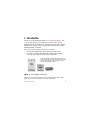
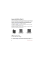
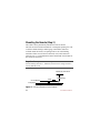
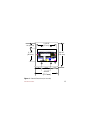
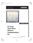
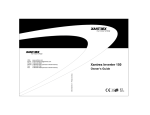
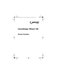
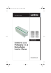
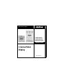
Smart choice for power
C40R/50 Remote
C40R/100 Remote
DVM/C40 Faceplate
Installation Guide
C-Series Meter
Display
www.xantrex.com
C-Series Meter Display
Installation Guide
About Xantrex
Xantrex Technology Inc. is a world-leading supplier of advanced power electronics and
controls with products from 50 watt mobile units to one MW utility-scale systems for
wind, solar, batteries, fuel cells, microturbines, and backup power applications in both
grid-connected and stand-alone systems. Xantrex products include inverters, battery
chargers, programmable power supplies, and variable speed drives that convert, supply,
control, clean, and distribute electrical power.
Trademarks
C-Series Meter Display is a trademark of Xantrex International. Xantrex is a registered
trademark of Xantrex International.
Other trademarks, registered trademarks, and product names are the property of their
respective owners and are used herein for identification purposes only.
Notice of Copyright
C-Series Meter Display Installation Guide © December 2003 Xantrex International. All
rights reserved.
Disclaimer
UNLESS SPECIFICALLY AGREED TO IN WRITING, XANTREX TECHNOLOGY INC. (“XANTREX”)
(a)
MAKES NO WARRANTY AS TO THE ACCURACY, SUFFICIENCY OR SUITABILITY OF ANY
TECHNICAL OR OTHER INFORMATION PROVIDED IN ITS MANUALS OR OTHER DOCUMENTATION.
(b)
ASSUMES NO RESPONSIBILITY OR LIABILITY FOR LOSS OR DAMAGE, WHETHER DIRECT,
INDIRECT, CONSEQUENTIAL OR INCIDENTAL, WHICH MIGHT ARISE OUT OF THE USE OF SUCH
INFORMATION. THE USE OF ANY SUCH INFORMATION WILL BE ENTIRELY AT THE USER’S RISK.
Date and Revision
December 2003 Revision A
Part Number
975-0123-01-01 Rev A
Contact Information
Telephone: 1 800 670 0707 (toll free North America)
1 360 925 5097 (direct)
Fax:
1 800 994 7828 (toll free North America)
1 360 925 5143 (direct)
Email:
[email protected]
Web:
www.xantrex.com
Contents
1. Introduction . . . . . . . . . . . . . . . . . . . . . . . . . . . . . . . . . . . . . . . . . . 1
2. Important Safety Information. . . . . . . . . . . . . . . . . . . . . . . . . . . . 2
Warnings and Cautions . . . . . . . . . . . . . . . . . . . . . . . . . . . . . . . . . 3
Additional Safety Guidelines . . . . . . . . . . . . . . . . . . . . . . . . . . . 3
3. Features . . . . . . . . . . . . . . . . . . . . . . . . . . . . . . . . . . . . . . . . . . . . . . 4
The Liquid Crystal Display (LCD) . . . . . . . . . . . . . . . . . . . . . . . . 5
Amp-Hour Reset and Backlight Button . . . . . . . . . . . . . . . . . . . . 6
LED Status Indicator . . . . . . . . . . . . . . . . . . . . . . . . . . . . . . . . . . . 6
4. Installation . . . . . . . . . . . . . . . . . . . . . . . . . . . . . . . . . . . . . . . . . . . 7
Jumper Installation (Step 1) . . . . . . . . . . . . . . . . . . . . . . . . . . . . . . 8
Cable Installation (Step 2) . . . . . . . . . . . . . . . . . . . . . . . . . . . . . . 10
Mounting the Remote (Step 3) . . . . . . . . . . . . . . . . . . . . . . . . . . 14
5. Operation . . . . . . . . . . . . . . . . . . . . . . . . . . . . . . . . . . . . . . . . . . . 17
Status Indicator . . . . . . . . . . . . . . . . . . . . . . . . . . . . . . . . . . . . . . 17
Resetting the Amp-Hour Meter . . . . . . . . . . . . . . . . . . . . . . . . . . 18
Turning the Display Backlight On or Off . . . . . . . . . . . . . . . . . . 18
6. Troubleshooting . . . . . . . . . . . . . . . . . . . . . . . . . . . . . . . . . . . . . . 18
7. Warranty and Return . . . . . . . . . . . . . . . . . . . . . . . . . . . . . . . . . 19
8. Other Xantrex Products . . . . . . . . . . . . . . . . . . . . . . . . . . . . . . . 26
iv
1 Introduction
Thank you for purchasing the Xantrex C-Series Meter Display. The
C-Series Meter Display is an optional accessory for the C-Series
Multifunction DC controllers C35, C40 and C60. It provides a digital
display of the voltage, current, and amp-hour status for the C-Series
Multifunction DC Controller.
The C-Series Meter Display comes in two versions:
• the faceplate (DVM/C40), which replaces the front cover.
• the remote (C40R/50 and C40R/100), which can be installed
remotely up to 1,000 feet away from the controller.
Note: The C40R/50 and C40R/100 comes with either a
50 or 100 foot cable. It can also be installed up to 1,000
feet from the Controller. However, Xantrex does not
provide cables exceeding 100 feet.
The Faceplate
The Remote
Figure 1 The Faceplate and Remote
Please note that labeling shown on the product photographs in this
guide may not exactly match the unit you purchased.
975-0123-01-01 Rev A
1
Read this guide before connecting or using the C-Series Meter Display,
and save it for future reference. The main topics in the guide are as
follows:
• “Important Safety Information” on page 2
• “Features” on page 4
• “Installation” on page 7
• “Operation” on page 17
• “Troubleshooting” on page 18
• “Warranty and Return” on page 19
2 Important Safety Information
Misusing or incorrectly connecting the C-Series Meter Display may
damage the equipment or create hazardous conditions for users. Read
the following safety instructions and pay special attention to all
Warnings and Cautions statements in the guide.
Warnings identify conditions that may result in personal injury or loss
of life.
Cautions identify conditions or practices that may damage the unit or
other equipment.
2
975-0123-01-01 Rev A
Warnings and Cautions
WARNING: Explosion Hazard
Do not use the C-Series Meter Display in the presence of flammable
fumes or gases. Do not use the C-Series Meter Display in an enclosure
containing automotive-type, lead-acid batteries. These batteries, unlike
sealed batteries, vent explosive hydrogen gas, which can be ignited by
sparks from electrical connections.
WARNING: Shock Hazard
Ensure all power sources are disconnected before proceeding.
Failure to follow these safety guidelines may cause personal injury
and/or damage to the C-Series Meter Display. It may also void your
product warranty.
Additional Safety Guidelines
Be sure to read, and adhere to, the Safety Guidelines listed in the
Owner’s Manual for the C-Series Multifunction DC Controller.
975-0123-01-01 Rev A
3
3 Features
The C-Series Meters have three features:
• a Liquid Crystal Display (LCD) to show current, voltage,
amperage, resettable amp hours and total amp hours,
• an Amp-hour Reset Button, which is also used to illuminate or dim
the display, and
• a Light Emitting Diode (LED) to indicate system status.
LCD Display
Amp-hour Reset/
Backlight Button
Status LED
The Remote
The Faceplate
Figure 2 Faceplate and Remote Features
The remote is supplied with either a 50-foot (15 m) or a 100-foot
(30.5 m) communications cable. Cable runs up to 1,000 feet (305 m) can
be used, but cables exceeding 100 feet are not provided by Xantrex.
4
975-0123-01-01 Rev A
The Liquid Crystal Display (LCD)
The LCD on the faceplate or remote provides the following information.
Information Type
Display Value/Range
Current from PV Array or DC Load
0 to 85 amps DC (in whole numbers only)
Battery Voltage
4 to 100 volts DC (in 0.2 volt increments)
Watts
0 to 3,600 watts (volts x amps)
Amp hours
0 to 65,536 Ah; can be reset to 0
Total amp hours
0 to 65,536 Ah; resets to zero when power
is disconnected
Status LED
green, red, or orange
Amps displayed in
whole numbers only
Amps
Watts
Volts
01.0
0013
13.1
00004.3
00013.2
Amp Hours
Total Amp Hours
Figure 3 LCD Features
The contrast of this display can be adjusted by a potentiometer located
on the back on the unit. The potentiometer is a black, round knob on the
circuit board next to the jumper pins. See page 9 for the location of this
potentiometer.
975-0123-01-01 Rev A
5
Amp-Hour Reset and Backlight Button
The amp-hour meter on the faceplate or remote can be reset by two
different methods.
Automatic resetting occurs when the C-Series Multifunction DC
Controller is first connected and activated and each time it’s
disconnected from the battery or the meter cable.
To manually reset the amp-hour meter, press and hold the push-button
on the front of the meter until the display resets.
This button also activates or deactivates the backlight for the LCD when
pressed and released immediately.
LED Status Indicator
The multicolor LED indicates the operating status of the controller. A
color-coded label is included on the cover of the controller explaining
the status LED’s indications. It blinks green, red, or orange depending
on the status of the system. The sequence of the flash also changes
depending on the operation of the controller at that time.
See page 17 for a basic description of these indications.
See the Owner’s Manual for the C-Series Multifunction DC Controller
for a more detailed description of the LED indications.
6
975-0123-01-01 Rev A
Important: The green and red color of the LED only indicates the
particular operating mode and the battery voltage level. It does not
indicate whether the charging source is functioning properly.
4 Installation
The following sections describe how to install the C-Series Meter
Display. They include detailed instructions for the following steps.
1.
2.
3.
Jumper Installation (Step 1): Set the voltage setting on the
faceplate or remote to match the system voltage by installing the
jumper over the appropriate pins. This step is critical to the proper
operation of the unit.
See “Jumper Installation (Step 1)” on page 8 for instructions.
Cable Installation (Step 2): Connect the display to the C-Series
controller using the communications cable.
See “Cable Installation (Step 2)” on page 10 for instructions.
Faceplate/Remote Installation (Step 3): Determine the location
and mounting method for the remote (if used).
See “Mounting the Remote (Step 3)” on page 14 for instructions.
975-0123-01-01 Rev A
7
Jumper Installation (Step 1)
Four sets of jumpers are located on the right side of the circuit board on
the back of the faceplate. Three jumpers set system voltage to 12 volts,
24 volts, or 48 volts. The fourth jumper dims the backlight on the
display to conserve power and improve accuracy when longer cable
runs are used. See Figure 5 for jumper locations.
To enable a selection, carefully slide the jumper over the top of both
pins. This is called installing the jumper.
To disable a selection, carefully slide the jumper over only one of the
pins. This is called removing the jumper.
Jumper
Jumper Installed
(Jumper is on both pins)
(Selection enabled)
Jumper Removed
(Jumper is only on one pin)
(Selection disabled)
Figure 4 Jumper Positions
To select and set the voltage:
◆ Install the jumper over the pins that correspond to the voltage of the
system. See Figure 5 for the location of the voltage jumpers.
8
975-0123-01-01 Rev A
Faceplate Circuit Board
(backside)
Remote Circuit Board
(backside)
Potentiometer for
LCD Contrast
Adjustment
Voltage
Jumpers
must match
system
voltage
Remove this jumper
for long cable runs,
dimming the display,
or conserving power.
Figure 5 Jumper Locations on the FacePlate and Remote
975-0123-01-01 Rev A
9
Cable Installation (Step 2)
Connect the display to the controller using the serial communications
cable provided. The cable is a six-conductor telephone cable with
modular-type connectors (RJ-15). Although any telephone-type cable
will work, the cables provided with the displays use stranded and
tin-plated wire for better performance and longer life.
The following instructions are illustrated in Figure 6.
To connect the Faceplate to the C-Series controller:
1.
2.
3.
4.
5.
10
Remove the front cover of the C-Series controller by removing the
four screws on the front cover of the unit.
Remove the LED on the circuit board of the C-Series controller
next to the RJ-15 Port just above the BATTERY POSITIVE connector.
If the LED must be replaced in the future, it will operate in either
orientation, except if replaced incorrectly, the color of the status
LED will be reversed.
Insert the serial communications cable from the faceplate into the
RJ-15 Port.
Align the faceplate on the front of the C-Series controller so that the
holes for the faceplate match.
Secure the faceplate in place using the four screws removed in
Step 1.
975-0123-01-01 Rev A
1
2
Remove these 4 screws
to access circuit board.
Remove this LED
(pull out).
RJ-15 Port
Faceplate (back)
3
Plug the Serial Communication
Cable into RJ-15 Port on the
circuit board.
4&5
Align the faceplate and
replace the 4 screws.
Figure 6 Connecting the Faceplate
975-0123-01-01 Rev A
11
To connect the remote:
1.
2.
3.
4.
5.
6.
Remove the front cover of the C-Series controller by removing the
four screws on the front cover of the unit.
Route one end of the serial communications cable (SCC) through a
knockout on the controller. Use a strain relief to hold and protect
the cable.
Plug this end of the yellow cable into the RJ-15 Port on the circuit
of the controller.
Route the other end of the SCC to where the remote display will be
located. Plug this end of the cable into RJ-15 Port on the backside
of the remote. Ensure you route it through the mounting surface
(i.e., wall or panel) if necessary.
Install the remote where desired. Four holes are provided for
installing screws or fasteners to secure the display in the mounting
surface.
See “Mounting the Remote (Step 3)” on page 14 for additional
information about how to mount the remote.
Secure the original faceplate in place using the four screws
removed in Step 1.
Important: The LED does not need to be removed when using
the remote.
12
975-0123-01-01 Rev A
1
RJ-15
Port
Remove these
4 screws to
access circuit
board.
Remote (back)
2
Route one end of SCC through
strain relief on controller.
3
Serial Communications Cable
(SCC)
Plug the SCC into the RJ-15 Port on
the circuit board of the controller.
Route the other end of the
SCC to the RJ-15 Port on
the back of the Remote.
5
Mount the display
up to 1,000 ft from
the controller.
4
6
Align the original
faceplate and replace
the 4 screws.
Figure 7 Connecting the Remote
975-0123-01-01 Rev A
13
Mounting the Remote (Step 3)
The remote can be permanently installed in a wall or cabinet.
The unit can also be flush-mounted into a rectangular opening in a wall
or surface-mounted using a double-gang, non-metallic outlet box.
To flush mount the remote, an opening must be cut in the backing
material to allow room for the circuit board, wires, and connectors.
Allow at least 1 ½ inch minimum clearance behind the circuit board for
the connectors and wires.
Important: Use great care when cutting out the area for the circuit board
from the backing material (i.e., wallboard). Ensure there is enough area left to
securely hold the screws.
Minimum Clearance
Circuit Board
Ports
1.5" (38 mm)
Faceplate
Figure 8 Minimum Clearance for the Remote
14
975-0123-01-01 Rev A
3 13/16"
(97 mm)
1.0" (25 mm)
4 9/16"
(116 mm)
2 3/8"
(60 mm)
1 3/8"
(35 mm)
1 13/16"
(46 mm)
1 3/8"
(35 mm)
4 9/16"
(116 mm)
Figure 9 Remote Dimensions (not to scale)
975-0123-01-01 Rev A
15
To Mount the Remote:
1.
2.
3.
4.
Use the remote as a template and mark the positions for the screw
holes. Mark the open area to be cut out for the circuit board.
Drill out the four screw’s holes and prepare wire access
opening/clearance. If using a double-gang, non-metallic, outlet box,
install it according to the manufacturer’s instructions.
Connect the communications cable (from the C-Series controller).
Secure the faceplate using screws (and anchors if necessary).
Mounting Holes
Mounting Holes
SAMPLE - Double-gang,
non-metallic, outlet box
Figure 10 Mounting the Remote
16
975-0123-01-01 Rev A
5 Operation
Status Indicator
The multicolor LED indicates the operating status of the controller. A
color-coded label is included on the cover of the controller explaining
the status LED’s indications.
• When in Charge Control mode, the LED will be green.
• When in Load Control mode, the LED will be red.
• When an Error Condition exists or the load has been disconnected,
the LED will be orange.
• When battery equalization is in process, the LED alternates
between red and green.
Important: The green and red LEDs only indicates the particular
operating mode and the battery voltage level. It does not indicate whether the
charging source is functioning properly.
See the Owner’s Manual for the C-Series Multifunction DC Controller
for additional information about the LED Status Indicator.
975-0123-01-01 Rev A
17
Resetting the Amp-Hour Meter
To manually reset the amp-hour meter, press and hold the push-button
on the front of the meter until the display resets.
The meter automatically resets if power is disrupted (for example, DC
cable is removed and replaced).
Turning the Display Backlight On or Off
Press and release the Amp-hour Reset button to turn the backlight
on or off.
6 Troubleshooting
If using long cable runs on the remote (greater than 100 feet) or if the
meter seems inaccurate, remove the jumper located below the voltage
configuration pins on the circuit board on the back of the unit. This dims
the LCD backlight, reduces power consumption, and improves meter
accuracy.
See the Owner’s Manual for the C-Series Multifunction DC Controller
for additional information about Troubleshooting.
18
975-0123-01-01 Rev A
7 Warranty and Return
Warranty
What does this warranty cover? This Limited Warranty is provided by
Xantrex Technology, Inc. ("Xantrex") and covers defects in workmanship and
materials in your C-Series Meter Display. This warranty period lasts for two
years from the date of purchase at the point of sale to you, the original end user
customer. Proof of purchase is required to make warranty claims.
This Limited Warranty is transferable to subsequent owners but only for the
unexpired portion of the Warranty Period. Subsequent owners also require proof
of purchase to validate this warranty.
What will Xantrex do? Xantrex will, at its option, repair or replace the
defective product free of charge, provided that you notify Xantrex of the product
defect within the Warranty Period, and provided that Xantrex through inspection
establishes the existence of such a defect and that it is covered by this Limited
Warranty.
Xantrex will, at its option, use new and/or reconditioned parts in performing
warranty repair and building replacement products. Xantrex reserves the right to
use parts or products of original or improved design in the repair or replacement.
If Xantrex repairs or replaces a product, its warranty continues for the remaining
portion of the original Warranty Period or 90 days from the date of the return
shipment to the customer, whichever is greater. All replaced products and all
parts removed from repaired products become the property of Xantrex.
975-0123-01-01 Rev A
19
Xantrex covers both parts and labor necessary to repair the product, and return
shipment to the customer via a Xantrex-selected non-expedited surface freight
within the contiguous United States and Canada. Alaska and Hawaii are
excluded. Contact Xantrex Customer Service for details on freight policy for
return shipments outside of the contiguous United States and Canada.
How do you get service? If your product requires troubleshooting or warranty
service, contact your merchant. If you are unable to contact your merchant, or
the merchant is unable to provide service, contact Xantrex directly at:
Telephone:
Fax:
Email:
1 800 670 0707 (toll free North America)
1 360 925 5097 (direct)
1 800 994 7828 (toll free North America)
1 360 925 5143 (direct)
[email protected]
Direct returns may be performed according to the Xantrex Return Material
Authorization Policy described in your product manual. For some products,
Xantrex maintains a network of regional Authorized Service Centers. Call
Xantrex or check our website to see if your product can be repaired at one of
these facilities.
What proof of purchase is required? In any warranty claim, dated proof of
purchase must accompany the product and the product must not have been
disassembled or modified without prior written authorization by Xantrex.
20
975-0123-01-01 Rev A
Proof of purchase may be in any one of the following forms:
•
•
•
The dated purchase receipt from the original purchase of the product at
point of sale to the end user, or
The dated dealer invoice or purchase receipt showing original equipment
manufacturer (OEM) status, or
The dated invoice or purchase receipt showing the product exchanged
under warranty
What does this warranty not cover? This Limited Warranty does not cover
normal wear and tear of the product or costs related to the removal, installation,
or troubleshooting of the customer's electrical systems. This warranty does not
apply to and Xantrex will not be responsible for any defect in or damage to:
a)
b)
c)
d)
the product if it has been misused, neglected, improperly installed, physically damaged or altered, either internally or externally, or damaged from
improper use or use in an unsuitable environment;
the product if it has been subjected to fire, water, generalized corrosion,
biological infestations, or input voltage that creates operating conditions
beyond the maximum or minimum limits listed in the Xantrex product
specifications including high input voltage from generators and lightning
strikes;
the product if repairs have been done to it other than by Xantrex or its
authorized service centers (hereafter "ASCs");
the product if it is used as a component part of a product expressly warranted by another manufacturer;
975-0123-01-01 Rev A
21
e)
the product if its original identification (trade-mark, serial number) markings have been defaced, altered, or removed.
Disclaimer
Product
THIS LIMITED WARRANTY IS THE SOLE AND EXCLUSIVE WARRANTY
PROVIDED BY XANTREX IN CONNECTION WITH YOUR XANTREX PRODUCT
AND IS, WHERE PERMITTED BY LAW, IN LIEU OF ALL OTHER WARRANTIES,
CONDITIONS, GUARANTEES, REPRESENTATIONS, OBLIGATIONS AND
LIABILITIES, EXPRESS OR IMPLIED, STATUTORY OR OTHERWISE IN
CONNECTION WITH THE PRODUCT, HOWEVER ARISING (WHETHER BY
CONTRACT, TORT, NEGLIGENCE, PRINCIPLES OF MANUFACTURER'S
LIABILITY, OPERATION OF LAW, CONDUCT, STATEMENT OR OTHERWISE),
INCLUDING WITHOUT RESTRICTION ANY IMPLIED WARRANTY OR
CONDITION OF QUALITY, MERCHANTABILITY OR FITNESS FOR A
PARTICULAR PURPOSE. ANY IMPLIED WARRANTY OF MERCHANTABILITY
OR FITNESS FOR A PARTICULAR PURPOSE TO THE EXTENT REQUIRED
UNDER APPLICABLE LAW TO APPLY TO THE PRODUCT SHALL BE LIMITED
IN DURATION TO THE PERIOD STIPULATED UNDER THIS LIMITED
WARRANTY.
IN NO EVENT WILL XANTREX BE LIABLE FOR ANY SPECIAL, DIRECT,
INDIRECT, INCIDENTAL OR CONSEQUENTIAL DAMAGES, LOSSES, COSTS OR
EXPENSES HOWEVER ARISING WHETHER IN CONTRACT OR TORT
INCLUDING WITHOUT RESTRICTION ANY ECONOMIC LOSSES OF ANY KIND,
ANY LOSS OR DAMAGE TO PROPERTY, ANY PERSONAL INJURY, ANY
22
975-0123-01-01 Rev A
DAMAGE OR INJURY ARISING FROM OR AS A RESULT OF MISUSE OR ABUSE,
OR THE INCORRECT INSTALLATION, INTEGRATION OR OPERATION OF THE
PRODUCT.
Exclusions
If this product is a consumer product, federal law does not allow an exclusion of
implied warranties. To the extent you are entitled to implied warranties under
federal law, to the extent permitted by applicable law they are limited to the
duration of this Limited Warranty. Some states and provinces do not allow
limitations or exclusions on implied warranties or on the duration of an implied
warranty or on the limitation or exclusion of incidental or consequential
damages, so the above limitation(s) or exclusion(s) may not apply to you. This
Limited Warranty gives you specific legal rights. You may have other rights
which may vary from state to state or province to province.
Warning: Limitations On Use
Please refer to your product manual for limitations on uses of the product.
SPECIFICALLY, PLEASE NOTE THAT THE C-SERIES METER DISPLAY SHOULD
NOT BE USED IN CONNECTION WITH LIFE SUPPORT SYSTEMS OR OTHER
MEDICAL EQUIPMENT OR DEVICES. WITHOUT LIMITING THE GENERALITY
OF THE FOREGOING, XANTREX MAKES NO REPRESENTATIONS OR
WARRANTIES REGARDING THE USE OF THE XANTREX C-SERIES METER
DISPLAY IN CONNECTION WITH LIFE SUPPORT SYSTEMS OR OTHER
MEDICAL EQUIPMENT OR DEVICES.
975-0123-01-01 Rev A
23
Return Material Authorization Policy
Before returning a product directly to Xantrex you must obtain a Return
Material Authorization (RMA) number and the correct factory "Ship To"
address. Products must also be shipped prepaid. Product shipments will be
refused and returned at your expense if they are unauthorized, returned without
an RMA number clearly marked on the outside of the shipping box, if they are
shipped collect, or if they are shipped to the wrong location.
When you contact Xantrex to obtain service, please have your instruction
manual ready for reference and be prepared to supply:
•
•
•
•
24
The serial number of your product
Information about the installation and use of the unit
Information about the failure and/or reason for the return
A copy of your dated proof of purchase
975-0123-01-01 Rev A
Return Procedure
1.
2.
3.
Package the unit safely, preferably using the original box and packing
materials. Please ensure that your product is shipped fully insured in the
original packaging or equivalent. This warranty will not apply where the
product is damaged due to improper packaging.
Include the following:
• The RMA number supplied by Xantrex Technology, Inc. clearly
marked on the outside of the box.
• A return address where the unit can be shipped. Post office boxes are
not acceptable.
• A contact telephone number where you can be reached during work
hours.
• A brief description of the problem.
Ship the unit prepaid to the address provided by your Xantrex customer
service representative.
If you are returning a product from outside of the USA or Canada In
addition to the above, you MUST include return freight funds and are fully
responsible for all documents, duties, tariffs, and deposits.
If you are returning a product to a Xantrex Authorized Service Center
(ASC) A Xantrex return material authorization (RMA) number is not required.
However, you must contact the ASC prior to returning the product or presenting
the unit to verify any return procedures that may apply to that particular facility.
975-0123-01-01 Rev A
25
Out of Warranty Service
If the warranty period for your C-Series Meter Display has expired, if the unit
was damaged by misuse or incorrect installation, if other conditions of the
warranty have not been met, or if no dated proof of purchase is available, your
C-Series Meter Display may be serviced or replaced for a flat fee.
To return your C-Series Meter Display for out of warranty service, contact
Xantrex Customer Service for a Return Material Authorization (RMA) number
and follow the other steps outlined in “Return Procedure” on page 25.
Payment options such as credit card or money order will be explained by the
Customer Service Representative. In cases where the minimum flat fee does not
apply, as with incomplete units or units with excessive damage, an additional fee
will be charged. If applicable, you will be contacted by Customer Service once
your unit has been received.
8 Other Xantrex Products
To see the range of inverters and chargers offered by Xantrex, visit our
web site at http://www.xantrex.com.
26
975-0123-01-01 Rev A
Xantrex Technology Inc.
1 800 670 0707 Tel toll free NA
1 360 925 5097 Tel direct
1 800 994 7828 Fax toll free NA
1 360 925 5143 Fax direct
[email protected]
www.xantrex.com
975-0123-01-01 Rev A
Printed in China