1
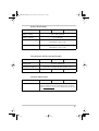
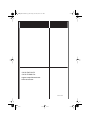
CR_Manual.book Page i Friday, June 24, 2005 12:31 PM
CR 1012E
CR 1024E
CR 1512E
CR 1524E
CR 2412E
CR 2424E
CR1012
CR1024
CR1512
CR1524
CR2412
CR2424
User Guide
Xantrex CR Series
Professional 2-in-1
Backup System
Inverter ⁄ Charger
Manual Typ
CR_Manual.book Page ii Friday, June 24, 2005 12:31 PM
CR_Manual.book Page iii Friday, June 24, 2005 12:31 PM
Contents
Important Safety Instructions - - - - - - - - - - - - - - - - - - - 1
Installation
Inverter to Charger Transition - - - - - - - - - - - - - - - - - - - - - - - Transfer Switching Speed - - - - - - - - - - - - - - - - - - - - - - - - - - Charger Terminology - - - - - - - - - - - - - - - - - - - - - - - - - - - - - CR Series Mounting - - - - - - - - - - - - - - - - - - - - - - - - - - - - - - Mounting on Wallboard - - - - - - - - - - - - - - - - - - - - - - - - - Mounting on Other Types of Walls - - - - - - - - - - - - - - - - - Battery Cable Connection - - - - - - - - - - - - - - - - - - - - - - - - - - DC Disconnect and Over-Current Protection - - - - - - - - - - - - - AC Connections - - - - - - - - - - - - - - - - - - - - - - - - - - - - - - - - - -
2
v
1
1
1
2
2
3
4
7
8
Operation
Front Panel Controls and LED Indicators - - - - - - - - - - - - - - - Power On/Off - - - - - - - - - - - - - - - - - - - - - - - - - - - - - - AC Mode LED - - - - - - - - - - - - - - - - - - - - - - - - - - - - - - Battery Mode LED - - - - - - - - - - - - - - - - - - - - - - - - - - - Charger LED - - - - - - - - - - - - - - - - - - - - - - - - - - - - - - - Battery Bank Capacity- - - - - - - - - - - - - - - - - - - - - - - - - RS232 Communications - - - - - - - - - - - - - - - - - - - - - - - -
11
11
11
12
12
12
12
Specifications - - - - - - - - - - - - - - - - - - - - - - - - - - - - - -
13
Warranty Information - - - - - - - - - - - - - - - - - - - - - - - - - -
17
A
iii
CR_Manual.book Page iv Friday, June 24, 2005 12:31 PM
About Xantrex
Xantrex Technology Inc. is a world-leading supplier of advanced power
electronics and controls with products from 50 watt mobile units to one MW
utility-scale systems for wind, solar, batteries, fuel cells, microturbines, and
backup power applications in both grid-connected and stand-alone systems.
Xantrex products include inverters, battery chargers, programmable power
supplies, and variable speed drives that convert, supply, control, clean, and
distribute electrical power.
Trademarks
Xantrex CR Series Professional 2-in-1 Backup System Inverter ⁄ Charger is a
trademark of Xantrex International. Xantrex is a registered trademark of
Xantrex International.
Other trademarks, registered trademarks, and product names are the property
of their respective owners and are used herein for identification purposes only.
Notice of Copyright
Xantrex CR Series Professional 2-in-1 Backup System Inverter ⁄ Charger User
Guide © June 2005 Xantrex International. All rights reserved.
Disclaimer
UNLESS SPECIFICALLY AGREED TO IN WRITING, XANTREX TECHNOLOGY INC.
(“XANTREX”)
(a) MAKES NO WARRANTY AS TO THE ACCURACY, SUFFICIENCY OR SUITABILITY
OF ANY TECHNICAL OR OTHER INFORMATION PROVIDED IN ITS MANUALS OR
OTHER DOCUMENTATION.
(b) ASSUMES NO RESPONSIBILITY OR LIABILITY FOR LOSS OR DAMAGE,
WHETHER DIRECT, INDIRECT, CONSEQUENTIAL OR INCIDENTAL, WHICH MIGHT
ARISE OUT OF THE USE OF SUCH INFORMATION. THE USE OF ANY SUCH
INFORMATION WILL BE ENTIRELY AT THE USER’S RISK.
Date and Revision
June 2005 Revision A
Contact Information
Telephone:
Fax:
Email:
Web:
iv
+34 93 470 5330
+34 93 473 6093
[email protected]
www.xantrex.com
CR_Manual.book Page v Friday, June 24, 2005 12:31 PM
Important Safety Instructions
WARNING
This chapter contains important safety and operating instructions.
Read and keep this Operation/Installation/Owner’s Guide or
Manual for future reference.
READ AND SAVE THESE INSTRUCTIONS
Before using the Xantrex CR Series Professional 2-in-1
Backup System Inverter ⁄ Charger (CR Series), read and obey
all instructions and cautionary markings on the CR Series, the
batteries, and in all sections of this instruction manual.
WARNING
The following warnings identify conditions or practices that could
lead to injury or loss of life
1. To reduce risk of fire and electric shock, Xantrex
recommends that all wiring be done by a qualified
electrician to ensure adherence to the local and national
electrical codes applicable in your application.
2. To reduce risk of injury and damage, charge only deepcycle lead acid type rechargeable batteries. Other types of
batteries may burst, causing personal injury and damage.
3. To reduce risk of shock or fire, do not disassemble the
CR Series. It contains no user-serviceable parts and
internal capacitors remain charged after all power is
disconnected. Take it to a qualified service center when
service or repair is required. Incorrect re-assembly may
result in risk of shock or fire.
4. To reduce risk of electric shock, disconnect all AC and
DC sources before attempting any maintenance or
cleaning. Turning off the CR Series will not reduce this
risk.
v
CR_Manual.book Page vi Friday, June 24, 2005 12:31 PM
Safety
5. To reduce risk of fire and electric shock, make sure that
existing wiring is in good condition and that wire is not
undersized. Do not operate the CR Series with damaged
or substandard wiring.
6. EXPLOSION HAZARD WORKING IN VICINITY OF
A LEAD ACID BATTERY IS DANGEROUS.
BATTERIES GENERATE EXPLOSIVE GASES
DURING NORMAL OPERATION. Provide ventilation
to outdoors from the battery compartment. The battery
enclosure should be designed to prevent accumulation
and concentration of hydrogen gas in "pockets" at the top
of the compartment. Vent the battery compartment from
the highest point. A sloped lid can also be used to direct
the flow to the vent opening location. Follow the
instructions in this manual and those of the battery
manufacturer regarding charging and ventilation.
7. EXPLOSION HAZARD: This equipment contains
components which tend to produce arcs or can spark. To
prevent fire or explosion, do not install the CR Series in
compartments containing batteries or flammable
materials or in locations that require ignition-protected
equipment. This includes any space containing gasolinepowered machinery, fuel tanks, or joints, fittings, or other
connections between components of the fuel system.
8. Do not operate the inverter/charger if it has received a
sharp blow, been dropped, or otherwise damaged in any
way. If the unit is damaged, see the Warranty information
elsewhere in this manual.
9. To reduce risk of shock hazard and damage, do not
expose the CR Series to rain, snow or liquids of any type.
The CR Series is designed for indoor mounting only.
Protect the CR Series from splashing if used in vehicle
applications.
10. The inverter/charger must be properly grounded and
provided with AC and DC disconnects and overcurrent
protection as specified in this manual and in accordance
with applicable electrical codes.
vi
CR_Manual.book Page vii Friday, June 24, 2005 12:31 PM
Safety
11. Be extra cautious when working with metal tools on, or
around batteries. The potential exists to drop a tool and
short-circuit the batteries or other electrical parts
resulting in sparks that could cause an explosion.
WARNING
Obey the following personal precautions while working with and
charging batteries. These warnings concern conditions or practices
that could lead to injury or loss of life.
1. Someone should be within range of your voice to come to
your aid when you work near batteries.
2. Have plenty of fresh water and soap nearby in case
battery acid contacts skin, clothing, or eyes.
3. Wear complete eye protection and clothing protection.
Avoid touching eyes while working near batteries. Wash
your hands when done.
4. If battery acid contacts skin or clothing, wash
immediately with soap and water. If acid enters eyes,
immediately flood eyes with running cool water for at
least 15 minutes and get medical attention immediately.
Baking soda neutralizes lead acid battery electrolyte.
Keep a supply on hand in the area of the batteries
5. NEVER smoke or allow a spark or flame in vicinity of a
battery or generator.
6. Be extra cautious when working with metal tools on, and
around batteries. Potential exists to short-circuit the
batteries or other electrical parts which may result in a
spark which could cause an explosion.
7. Remove personal metal items such as rings, bracelets,
necklaces, and watches when working with a battery. A
battery can produce a short-circuit current high enough to
weld a ring, or the like, to metal causing severe burns.
vii
CR_Manual.book Page viii Friday, June 24, 2005 12:31 PM
Safety
CAUTION
The following cautions identify conditions or practices that could
result in damage to the inverter/charger or other equipment
1. To reduce the risk of overheating, keep the ventilation
openings clear and do not install the CR Series in a
compartment with limited airflow. Maintain adequate
clearance around the sides of the unit. Refer to the
installation instructions in this manual.
2. Never charge a frozen battery.
viii
CR_Manual.book Page 1 Friday, June 24, 2005 12:31 PM
1
Installation
Inverter to Charger Transition
The internal battery charger and automatic transfer relay allow
the unit to operate as either a battery charger or inverter (but
not both at the same time). The Xantrex CR Series Professional
2-in-1 Backup System Inverter ⁄ Charger (CR Series)
automatically becomes a battery charger whenever AC power
is supplied to its AC input, while also passing the incoming AC
power through to the loads on the CR Series' AC output (load)
terminals
Transfer Switching Speed
While the CR Series is not designed specifically to operate as
an uninterruptible power supply system (UPS), its transfer time
is normally fast enough to maintain the power for computers.
The transfer time is a maximum of 20 milliseconds.
Charger Terminology
Constant current stage During this stage of the charge
cycle, the batteries are charged at a constant current, ensuring
rapid replacement of most of the battery's charge.
Constant voltage stage During this stage of the charge
cycle, the batteries are held at a constant voltage and accept
whatever current is required to maintain this voltage. This
stage ensures replacement of the remaining charge not replaced
during the constant current stage, while preventing the
batteries from being over-charged.
1
CR_Manual.book Page 2 Friday, June 24, 2005 12:31 PM
Installation
CR Series Mounting
The Xantrex CR Series Professional 2-in-1 Backup System
Inverter ⁄ Chargers can weigh as much as 45 lb. (20kg).
Mounting on Wallboard
Wallboard is not strong enough to support its weight so
additional support must be added. The easiest method for
securing it to an existing wall is to place two 2 in. x 4 in.
boards horizontally on the wall (spanning at least three studs)
and securing the CR Series to those boards.
WARNING: Unit is heavy
To avoid personal injury, use appropriate lifting techniques. Have
extra people on hand to assist in lifting the CR Series into position
while it is being secured.
WARNING
Do not mount the CR Series using only the keyhole slots for
mounting hardware. Use mounting bolts in at least two of the round
holes in addition.
To mount the CR Series:
1. Locate the studs and mark their location on the wall.
2. Measure the desired height from the floor for the CR
Series to be mounted.
3. Using a level, run a horizontal line. The length of the line
must span at least 3 studs.
4. Place a pre-cut 2 in. x 4 in. board on the marked location
and drill pilot holes through the board and studs.
5. Secure the 2 in. x 4 in. board to the 3 studs with #10
wood screws long enough to penetrate 1-1/2 inches into
the studs.
6. Repeat the above procedure for the second 2 in. x 4 in.
board.
2
CR_Manual.book Page 3 Friday, June 24, 2005 12:31 PM
CR Series Mounting
7. Drill pilot holes for the mounting bolts into the 2 in. x
4 in. boards, referring to Figure 1-1 for locations.
8. With assistance, lift the CR Series into position, and
secure it to the 2 in. x 4 in. boards using ¼ x 1½ in. lag
bolts and washers in at least 6 locations.
Alternatively, a half or quarter sheet of ¾ in. plywood can
also be used as a backing, with the CR Series Backup System
mounted directly to the plywood using ¼ in. diameter lag
bolts and washers. The plywood must span and be secured to
three studs for adequate support.
Figure 1-1 Dimensional Drawings for Screw Hole Placement
Mounting on Other Types of Walls
As the mounting walls may be made of materials other than
wood, the above detailed mounting hole location drawing and
method is valid, providing the local mounting codes are met.
You will need to refer to your local building codes in order to
determine what type of mounting equipment is needed to
securely mount the 45 lb. (20kg) CR Series.
3
CR_Manual.book Page 4 Friday, June 24, 2005 12:31 PM
Installation
Battery Cable Connection
WARNING: Risk of overheating and fire
Risk of overheating and fire. Under-sized cables, loose
connections, or improper connections will overheat. Use the
recommended cable sizes below. Do not place anything between
the flat part of the CR Series terminal and the battery cable ring
terminal. Do not apply any type of anti-oxidant paste to terminals
until after the battery cable wiring is torqued. Tighten the nuts on
the DC terminals to 10 to 15 foot-pounds of torque.
CAUTION
Reverse polarity connection of the battery will damage the inverter/
charger and is not covered by your warranty. Ensure correct
polarity (positive to positive, negative to negative) before
completing the connections from the battery to the CR Series.
Important: Run the positive and negative battery cables as
close to each other as possible, using cable ties or clamps to hold
them together. This reduces the effect of inductance, produces a
better waveform, and increases efficiency.
Figure 1-2 illustrates the proper method to connect the
battery cables to the CR Series terminals.
4
Battery Cable Connection
CAUTION
Do not place anything between the battery cable ring terminals and
the terminals on the inverter. The terminal stud is not designed to
carry current. Apply anti-oxidant paste to the terminals only after
their terminals have been torqued.
Figure 1-2 Battery Cable Connection to CR Series
Table 1-1 provides recommended minimum cable sizes for
various cable lengths and inverter amperages.
5
CR_Manual.book Page 6 Friday, June 24, 2005 12:31 PM
Installation
Table 1-1 Minimum Recommended Battery Cable Size Versus Length
Typical
Full Load
DC Input
Current
Minimum
Recommended
Cable Sizea for
any length run
Minimum
Recommended
Cable Size for
Lengths up to
10 ft each wayb
Minimum
Recommended
Cable Size for
Lengths up to
20 ft each wayb
CR1012
CR1012E
100 A
No. 4 AWG
No. 2 AWG
No. 0 AWG
CR1024
CR1024E
50 A
No. 8 AWG
No. 6 AWG
No. 2 AWG
CR1512
CR1512E
150 A
No. 1 AWG
No. 1 AWG
No. 3/0 AWG
CR1524
CR1524E
75 A
No. 6 AWG
No. 4 AWG
No. 1 AWG
CR2412
CR2412E
240 A
No.2/0 AWG
No. 3/0 AWG
No. 3/0 AWG
CR2424
CR2424E
120 A
No. 2 AWG
No. 2 AWG
No. 2/0 AWG
Inverter
Model
a. Based on the US National Electrical Code, NFPA 70, Table 310-17, for 75° C
single-insulated cables
b. Based on max. total cable voltage drop of 0.5V at full load
Important: Increasing the size of the cables and keeping them
as short as possible will greatly improve inverter surge
performance and will reduce the likelihood of nuisance outages
(due to undervoltage shutdown, DC breaker tripping, or open
fuses).
6
CR_Manual.book Page 7 Friday, June 24, 2005 12:31 PM
DC Disconnect and Over-Current Protection
DC Disconnect and Over-Current Protection
For safety and to comply with regulations, battery overcurrent protection and disconnect devices are required. Fuses
and disconnects must be sized to protect the DC cable size
used, and must be rated for DC operation. Do not use devices
rated only for AC service - they will not function properly.
Note that some installation requirements may not require a
disconnect device, although over-current protection is still
required. Xantrex offers a fuse block (model TFB) providing
the code- required inverter over-current protection for these
applications. Refer to the table below for the proper size
over-current protection (fuse or breaker) for specific cable
sizes listed in Table 1-2.
Table 1-2 Battery Cable to Maximum Breaker/Fuse Size
Cable Size Required
Maximum
Current Ratinga
Maximum
Breaker Size
No. 8 AWG
70 A
70
No. 6 AWG
95 A
100
No. 4 AWG
125 A
125
No. 2 AWG
170 A
175
No. 1 AWG
195 A
200
No. 0 AWG
230 A
250
No. 2/0 AWG
265 A
300
No. 3/0 AWG
310 A
350
a.Based on the US National Electrical Code, NFPA 70, Table
310-17, for 75 C single-insulated cables
7
CR_Manual.book Page 8 Friday, June 24, 2005 12:31 PM
Installation
AC Connections
WARNING: Shock and fire hazard
Ensure all AC and DC sources are disconnected at the source
before beginning wiring. Turning off the CR Series will not reduce
this hazard. Xantrex recommends that all wiring be done by a
qualified electrician to ensure adherence to the local and national
electrical codes applicable in your application.
On the right end of the chassis is the AC hardwire cover or
conduit box (dependent on the power level). A six-position
terminal block is provided to make the AC input, AC output,
and ground connections. Consult the applicable electrical
codes to determine any AC input and output overcurrent
protection and disconnect switches that may be required. The
AC breakers in a sub-panel may meet this requirement.
To make AC connections:
1. Disconnect the CR Series from the battery either by
turning off the battery switch or removing the battery
cables from the battery. Disconnect the AC source by
opening the appropriate circuit breaker in the AC panel
supplying the circuit.
2. Feed the wires through appropriate conduit and the AC
cover. In certain installations, conduit fittings may be
replaced with strain reliefs, consult local and national
codes. See Figure 1-3.
3. Following the wiring guide located in the AC wiring
compartment (see Figure 1-3), connect the safety ground
(bare, green or green and yellow), line (black or brown),
and neutral (white or blue) wires from the AC input
(utility, generator, etc.) to the terminal block and tighten
to 10-15 inch pounds torque.
8
AC Connections
Figure 1-3 AC Connections
4. Following the wiring guide located in the AC wiring
compartment (see Figure 4), connect the safety ground
(bare, green or green and yellow), line (black or brown),
and neutral (white or blue) wires from the AC output
(loads) to the terminal block and tighten to 10-15 inch
pounds torque.
5. Use the two M3 screws to secure the AC wiring
compartment cover back in place over the terminals.
6. If using cable clamps, tighten the clamps on the AC cable
jackets (not the individual wires) to provide strain relief
for the connections.
9
CR_Manual.book Page 10 Friday, June 24, 2005 12:31 PM
10
CR_Manual.book Page 11 Friday, June 24, 2005 12:31 PM
2
Operation
Front Panel Controls and LED Indicators
Shown below are the controls and indicator lights on the front
of the CR Series series. They control and provide information
in either inverter or battery charging mode of operation. All
models of the CR Series series operate identically.
Figure 2-1 Control Panel
Power On/Off
Located on the left of the panel is the POWER ON/OFF
button. Once the CR Series has been properly installed and
the batteries are connected, press this button for 2 seconds
and the CR Series will automatically turn on and off.
AC Mode LED
This green LED lights up when the AC output power is
available.
11
CR_Manual.book Page 12 Friday, June 24, 2005 12:31 PM
Operation
Battery Mode LED
This orange LED lights up when the unit is in battery mode
(using power from batteries).
Charger LED
Yellow This indicates that the charger is in the first stage
(constant current stage).
Blinking Yellow This indicates that the charger is in the
second stage (constant voltage stage).
Red light This indicates one of the following possible
failures: overload, overcharge, battery voltage too high,
battery voltage too low, and fan failure. Inverter will shut
down. To restart inverter, press power on/off switch once
fault is corrected
Battery Bank Capacity
The BATTERY BANK CAPACITY control is used to inform
the microprocessor about the size of the battery bank being
used. Battery bank size is adjustable from 100 to 1000 amphours. Set this adjustment to the setting closest to the size of
your battery bank (in amp-hours). The charge current will be
set at 0.1 (Ahr) up to 40 A/50 A max (12 V) and 20 A/25 A
max (24 V).
RS232 Communications
Used for factory upgrades and optional monitory software.
12
A
Specifications
Table A-1 Invert Mode Specifications
MODEL
CR-1000
CR-1500
CR-2400
AC Output Power
13
CR_Manual.book Page 14 Friday, June 24, 2005 12:31 PM
Table A-2 Charge and Bypass Mode Specifications
MODEL
CR-1000
CR-1500
120VAC / 230VACa
Nominal AC Input
Voltage
AC Input Voltage Range
CR-2400
85VAC-132VAC / 184VAC-253VACa ± 4%
Acceptable Voltage
Range
95-127VAC / 194-243VACa
Nominal AC Input
Frequency
50Hz or 60Hz
AC Input Frequency
Range
47Hz~53Hz or 57Hz~63Hz ± 0.3Hz
Max Total AC Input
Current (Charge +
Bypass)
14 Arms at 120Vac
7.4 Arms at 230Vaca
18.1 Arms at 120Vac
9.4 Arms at 230Vaca
27 Arms at 120Vac
14.1 Arms at 230Vac a
Rated AC Bypass
Current
8.3 Arms at 120Vac
4.4 Arms at 230Vaca
12.5 Arms at 120Vac
6.5 Arms at 230Vaca
20 Arms at 120Vac
10.4 Arms at 230Vac a
Charging Voltage
12V battery: 13.5Vdc
24V battery: 27.0Vdc
Charging Current
(Depending on battery
capacity)
12V battery: 0-40A and 0-50A
24V battery: 0-20A and 0-25A
Transfer Time (AC to
DC)
20 ms (typical)
Transfer Time (DC to
AC)
20 ms (typical)
Overcharging Protection
a. 230V, 50Hz models
14
12V battery: 15V
24V battery: 30V
CR_Manual.book Page 15 Friday, June 24, 2005 12:31 PM
Table A-3 Battery Specifications
MODEL
CR-1000
CR-1500
CR-2400
Battery Voltage
12V or 24V nominala
Battery Capacity
Up to 1000AH
Low Battery Warning
12V battery: 11V ± 0.2V
24V battery: 22V ± 0.2V
Low Battery Shutdown
12V battery: 10.5V ± 0.2V
24V battery: 21V ± 0.2V
a. 24Vdc models
Table A-4 Environmental and Physical Specifications
MODEL
CR-1000
Temperature
Dimensions DxWxH
Net Weight
CR-1500
CR-2400
0 to 40°C Maximum
579 x 227 x 179mm (22.8in. x 8.9in. x 7in.)
18kg (40 lbs.)
20kg (44 lbs.)
27.5kg (61 lbs.)
Table A-5 Interface Specifications
MODEL
CR-1000
CR-1500
CR-2400
Smart RS-232
Used for factory upgrade
Supports Windows 95/98/NT/2000/XP, Novell, and Linux
Visit www.xantrex.com for more information about the CR
Series inverter chargers
15
CR_Manual.book Page 16 Friday, June 24, 2005 12:31 PM
16
CR_Manual.book Page 17 Friday, June 24, 2005 12:31 PM
Warranty Information
Limited Warranty for:
Xantrex CR Series Professional 2-in-1 Backup System
What does this warranty cover and how long does it last? This Limited Warranty is
provided by Xantrex Technology Inc. ("Xantrex") and covers defects in workmanship and
materials in your Xantrex CR Series product. This warranty lasts for a Warranty Period of
1 year from the date of purchase at point of sale to you, the original end user customer.
What will Xantrex do? Xantrex will, at its option, repair or replace the defective product
free of charge, provided that you notify Xantrex of the product defect within the Warranty
Period, and provided that Xantrex through inspection establishes the existence of such a
defect and that it is covered by this Limited Warranty.
Xantrex will, at its option, use new and/or reconditioned parts in performing warranty
repair and building replacement products. Xantrex reserves the right to use parts or
products of original or improved design in the repair or replacement. If Xantrex repairs or
replaces a product, its warranty continues for the remaining portion of the original
Warranty Period or 90 days from the date of the return shipment to the customer,
whichever is greater. All replaced products and all parts removed from repaired products
become the property of Xantrex.
How do you get service?
If your product requires troubleshooting or warranty service, contact your dealer. If you
are unable to contact your dealer, or the dealer is unable to provide service, contact
Xantrex directly at:
Phone:
Fax:
Email:
+34 93 470 5330
+34 93 473 6093
[email protected]
In any warranty claim, dated proof of purchase must accompany the product and the
product must not have been disassembled or modified without prior written authorization
by Xantrex.
Proof of purchase may be in any one of the following forms:
• The dated purchase receipt from the original purchase of the product at point of sale to
the end user, or
• The dated invoice or purchase receipt showing the product exchanged under warranty
What does this warranty not cover? This Limited Warranty does not cover normal
wear and tear of the product or costs related to the removal, installation, or troubleshooting
of the customer's electrical systems. This warranty does not apply to and Xantrex will not
be responsible for any defect in or damage to:
a) the product if it has been misused, neglected, improperly installed, physically
damaged or altered, either internally or externally, or damaged from improper
use or use in an unsuitable environment;
b) the product if it has been subjected to fire, water, excessive corrosion, biological
infestations, or input voltage that creates operating conditions beyond the
maximum or minimum limits listed in the Xantrex product specifications
including high input voltage from generators and lightning strikes;
c) the product if repairs have been done to it other than by Xantrex or its authorized
service centers (hereafter "ASCs");
d) the product if it is used as a component part of a product expressly warranted by
another manufacturer;
e) the product if its original identification (trade-mark, serial number) markings
have been defaced, altered, or removed.
17
CR_Manual.book Page 18 Friday, June 24, 2005 12:31 PM
Warranty Information
DISCLAIMER OF WARRANTY
THIS LIMITED WARRANTY IS THE SOLE AND EXCLUSIVE WARRANTY PROVIDED BY
XANTREX IN CONNECTION WITH YOUR XANTREX PRODUCT AND IS, WHERE
PERMITTED BY LAW, IN LIEU OF ALL OTHER WARRANTIES, CONDITIONS,
GUARANTEES, REPRESENTATIONS, OBLIGATIONS AND LIABILITIES, EXPRESS OR
IMPLIED, STATUTORY OR OTHERWISE IN CONNECTION WITH THE PRODUCT,
HOWEVER ARISING (WHETHER BY CONTRACT, TORT, NEGLIGENCE, PRINCIPLES OF
MANUFACTURER'S LIABILITY, OPERATION OF LAW, CONDUCT, STATEMENT OR
OTHERWISE), INCLUDING WITHOUT RESTRICTION ANY IMPLIED WARRANTY OR
CONDITION OF QUALITY, MERCHANTABILITY OR FITNESS FOR A PARTICULAR
PURPOSE. ANY IMPLIED WARRANTY OF MERCHANTABILITY OR FITNESS FOR A
PARTICULAR PURPOSE TO THE EXTENT REQUIRED UNDER APPLICABLE LAW TO
APPLY TO THE PRODUCT SHALL BE LIMITED IN DURATION TO THE PERIOD
STIPULATED UNDER THIS LIMITED WARRANTY.
IN NO EVENT WILL XANTREX BE LIABLE FOR ANY SPECIAL, INDIRECT, INCIDENTAL
OR CONSEQUENTIAL DAMAGES, LOSSES, COSTS OR EXPENSES HOWEVER ARISING
WHETHER IN CONTRACT OR TORT INCLUDING WITHOUT RESTRICTION ANY
ECONOMIC LOSSES OF ANY KIND, ANY LOSS OR DAMAGE TO PROPERTY, ANY
PERSONAL INJURY, ANY DAMAGE OR INJURY ARISING FROM OR AS A RESULT OF
MISUSE OR ABUSE, OR THE INCORRECT INSTALLATION, INTEGRATION OR
OPERATION OF THE PRODUCT.
Exclusions This Limited Warranty gives you specific legal rights. You may have other
rights which may vary depending on the country, province, or state.
WITHOUT LIMITING THE GENERALITY OF THE FOREGOING, UNLESS SPECIFICALLY
AGREED TO BY IT IN WRITING, XANTREX
(a) MAKES NO WARRANTY AS TO THE ACCURACY, SUFFICIENCY OR
SUITABILITY OF ANY TECHNICAL OR OTHER INFORMATION PROVIDED IN
MANUALS OR OTHER DOCUMENTATION PROVIDED BY IT IN CONNECTION
WITH THE PRODUCT; AND
(b) ASSUMES NO RESPONSIBILITY OR LIABILITY FOR LOSSES, DAMAGES,
COSTS OR EXPENSES, WHETHER SPECIAL, DIRECT, INDIRECT,
CONSEQUENTIAL OR INCIDENTAL, WHICH MIGHT ARISE OUT OF THE USE
OF SUCH INFORMATION.
THE USE OF ANY SUCH INFORMATION WILL BE ENTIRELY AT THE USER'S RISK.
WARNING: LIMITATIONS ON USE
Please refer to your product user manual for limitations on uses of the product.
Specifically, please note that the CR Series is not intended for use in connection with life
support systems and Xantrex makes no warranty or representation in connection with any
use of the product for such purposes.
Xantrex Technology, Inc.
8999 Nelson Way
Burnaby, British Columbia
Canada V5A 4B5
18
CR_Manual.book Page 19 Friday, June 24, 2005 12:31 PM
CR_Manual.book Page 20 Friday, June 24, 2005 12:31 PM
Xantrex Technology Inc.
+34 93 470 5330 Tel
+34 93 473 6093 Fax
[email protected]
www.xantrex.com
Printed in China