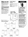
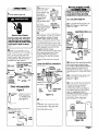
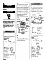
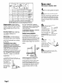
1
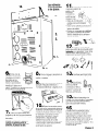
Before you start...
Check location where dryer will be
installed. Proper installation is your
responsibility. The dryer must not be
installed or stored in an area where it
will be exposed to water and/or
weather. Make sure you have
everything
necessary for correct
installation.
Grounded electrical
supply
See Electrical requirements,
is required.
Pages 3-4.
Important: Observe all
governing codes and
ordinances.
Open dryer and remove literature and
parts packages.
Support: Floor must be sturdy enough
to support dryer weight of 175 pounds
(79.4 kg)
Level floor: 1-inch (2.5 cm) maximum
slope under entire dryer.
Electrical Shock Hazard
It is the customer’s responsibility:
To contact a qualified electrical
installer.
To assure that the electrical
installation is adequate
and in
conformance
with National
Electrical Code, ANSVNFPA 70 latest edition*, and all local codes
and ordinances.
Failure to do so could result in death
or serious injury.
Four-inch metal exhaust duct is
required.
Check code requirements:
Some
codes limit or Do Not permit installation
of clothes dryers in garages, closets,
mobile homes, or sleeping quarters.
Contact your local building inspector.
Protection from the weather: Proper
operation
of dryer cycles requires
temperatures
above 45°F (7.2”C), or
the dryer may not shut off when
automatic
cycles are used.
Fire Hazard
Do Not store gasoline, paint thinners,
or other flammable
materials near
dryer. Fumes from such materials
may result in fire or explosion.
Never install dryer up against
draperies or curtains or on carpet.
Keep any and all items from falling
or collecting
behind the dryer.
If you install the dryer in a garage,
carport, or areas near vehicles
where fumes from gasoline or other
flammable
materials may be
present, the vapors may be heavier
than air and remain near floor.
Place dryer a minimum of 18 inches
(45.7 cm) above floor. Check with
your building inspector regarding
requirements
for this installation.
Failure to follow these instructions
could result in a fire or explosion.
42-318”
(107.6 cm)
Dryer door clearances
Location must be large enough to fully
open dryer door. See Page 10 for
recessed and closet requirements.
15-318”
(39.1 cm)
(58.4 cm)
+
-
r4
Copies of the standards
be obtained from:
*National
Fire Protection
Batterymarch
Park
Quincy, Massachusetts
large sideswing door
I
Full-width
hamper door
Page 2
Extra-large
hamper door
(shown above)
Mini-hamper
door
listed above
Association
02269
may
Tools and
materials needed
for installation:
Electrical
requirements
It is the personal responsibility and
obligation
of the customer to contact
a qualified electrician
to assure that
the electrical
installation is adequate
and is in conformance
with the
National Electrical Code, ANSVNFPA
70 - latest* and all local codes and
ordinances.
Copies of the standards
be obtained
from:
*National Fire Protection
Batterymarch
Park
Quincy, Massachusetts
listed above
may
Association
02269
Important: Observe all governing
codes and ordinances.
l
duct tape
l/4” socket
wrench or nut
driver (shown)
1” socket
wrench
safety glasses
Parts supplied
for installation:
Remove parts from packages.
that all parts were included.
4 leveling
legs
literature
Check
package
Electrical Shock Hazard
Electrical ground is required on this
appliance.
Do Not modify the power supply
cord plug. If it does not fit the outlet,
have a proper outlet installed by a
qualified electrician.
Do Not have a fuse in the neutral or
grounding
circuit. A fuse in the
neutral or grounding
circuit could
result in an electrical
shock.
Do Not use an extension cord with
this appliance.
Check with a qualified electrician
to
be sure this appliance
is properly
grounded.
Do Not connect plug end of power
supply cord into a live receptacle
before connecting
power supply
cord to dryer terminal block.
Do Not reuse old power supply
cord.
Failure to follow these instructions
could result in death or serious
injury.
Power supply cord
Use a new 30-amp power supply
cord.
Local codes may permit the use of a
U.L.-listed, 120/240-volt minimum,
30-ampere,
dryer power supply cord kit
(pigtail). Power supply cord should be
Type SRD or SRDT and be at least four
feet (1.2 m) long. The wires that
connect to the dryer must end with
ring terminals or spade terminals with
upturned ends. A 3/4”, U.L.-listed strain
relief must be installed where the
power supply cord connects to the
dryer (see Figures 1 and 2).
upturned
rina
terSinals
to this conductor.
If codes permit and a separate
grounding wire is used, it is
recommended
that a qualified
electrician
determine
that the
grounding
path is adequate.
A three-wire or four-wire, single phase
120/240-volt, 60-Hz, AC-only, electrical
supply (or three-wire or four-wire
120/208-volt if specified on serial/rating
plate) is required on a separate
30-ampere
circuit, fused on both sides
of the line. A time-delay
fuse or circuit
breaker is recommended.
w
wirina
314” U.L.-listed /
strain relief
NEUTRAL
(white or center)
Three-wire power supply cord
NEMA lo-30P
Figure 1
314” U.L.-listed
strain relief
\
F
NEUTRAL
(white),
NEUTRAL
grounding
A wiring diagram
the console
back panel
dryer.
ends
or on
of
prong
(green)
ring
\
terminals
Four-wire power supply cord
(Mobile home or
other four-wire installations)
NEMA 14-30P
Figure 2
Page 3
For use where
flexible power
local codes permit
supply cord.
Electrical
connection
use of
Ill
@ @
i..:
three-wire
receptacle(lO-30R)
Figure 3
four-wire
receptacle(l4-
30R)
Figure 4
The power supply cord must have
three, No.-1 0 copper wires to match a
three-wire receptacle
of NEMA Type
1O-30R (see Figure 3).
For mobile homes or other four-wire
installations, the power supply cord
must have four, No.-1 0 copper wires
and match a four-wire receptacle
of
NEMA Type 14-30R (see Figure 4). The
fourth wire (grounding
conductor)
must
be identified with a green cover and
the neutral conductor
by a white
cover.
3 . Attach
314”
J.L.-listed strain
relief (U.L.
marking on strain
,elief) to the hole
oelow terminal
olock opening
:see Figure 6).
Tighten strain
,elief firmly to
strAn relief
cabinet so it is in
(outside dryer)
a horizontal
oosition. Place
Figure 6
3ower supply
cord through strain relief.
Where local codes permit connecting
frame-grounding
conductor
to the
neutral wire:
This dryer is manufactured
with the
frame-grounding
conductor
connected
to the NEUTRAL (center)
the wiring harness at the terminal
block. If local codes Do Not permit
type of connection,
use “Four-wire
Connection”
instructions.
of
this
4 . Loosen
or remove terminal
olock screws. Connect the neutral
dire (white or center) of power
;upply cord under the center screw
of the terminal block.
Connect the other two wires to
outer terminal block screws (see
‘igure 7).
Tighten all terminal block screws
‘irmly.
Center wire MUST be connected
to
zenter screw.
Direct wire
The dryer can be connected
directly
to fused disconnect
or circuit breaker
box with three-wire or four-wire flexible
armored or non-metallic
sheathed
copper cable (with grounding
wire).
Do Not use two-wire with bare
grounding
wire. All current-carrying
wires must be insulated,
A conduit connector
must be installed
at junction box. USE ONLY lo-GAUGE
SOLID COPPER WIRE, DO NOT USE
ALUMINUM WIRE. Allow four feet of
slack in the line so dryer can be moved
if servicing is ever necessary.
Electrical Shock Hazard
Check that wiring you are using
matches colors shown in illustrations
and specified in instruction steps. If
wiring does Not match, it is your
responsibility
to have a qualified
electrician
install the correct wiring.
Failure to install the correct wiring
could result in death or serious
injury.
strain relief
screws
Figure 7
1 . Turn power
supply
2.
Remove holddown
‘erminal block cover.
Figure 5
Page 4
off.
screw and
5'. Tighten
6 . Insert
strain relief screws.
tab of terminal block
:over into slot of the dryer rear
panel (see Figure 5). Secure cover
with hold-down
screw.
4 . Attach
I
n
Turn power
supply
3/4” U.L.rear
listed strain relief
(U.L. marking on
strain relief) to the
hole below
terminal block
rer
opening (see
figure 11).
Tighten strain relief ’
P
firmly to cabinet
strain relief
so it is in a
horizontal position.
(outs’de dVer)
Place Power suPPlY
11
cable through
strain relief. -
ivI
off.
Figure
Electrical Shock Hazard
Do Not use two wire cable with a
bare grounding
wire. All currentcarrying wires must be insulated.
Failure to install the correct wiring
could result in death or serious
injury.
2. Strip 3-l /2 inches
(8.9 cm) of
)uter covering from end of cable. If
rsing three-wire cable with groundin
vire, cut the bare wire even with
)uter covering.
Strip 1 inch (2.5 cm)
)f insulation from the end of each
Isulated wire (see Figure 8).
Bare wire cut short. Wire
is not used. Dryer is
grounded
through direc
wire cable.
~~~~r~(i~ted
\
5 . Loosen or remove terminal
block screws. Connect the neutral
wire (white or center) of power
supply cable under the center
screw of the terminal block. Place
the hook-shaped
end of the wire
over the terminal block screw with
open side of the hook facing to the
right. Squeeze hook end of wire
together to form a loop.
Connect the other two wires under
the outer terminal block screws.
Attach wires using the same
method as the neutral wire (see
Figure 12).
Tighten all terminal block screws
firmly.
Center wire MUST be connected
center screw.
to
external
nter
must
(attache<
at facton
1O-gauge,
3-wrre with
grounding
wire (Romex)
Direct wire preparation
Figure 8
u-shaped
hook
screws
Shape the end of
each wire into a
‘U” shaped hook
(see Figure 9).
6
Figure 9
hold-down
erminal block cover.
screw and
external grounding
connector
terminal
block cover
a
6 . Tighten
7
3 . Remove
tab
Figure 12
holddown
screw
Where local codes DO NOT permit
connecting
the frame-grounding
conductor to the neutral (white) wire:
1 Q. Turn power
supply
off.
&I. Complete
Power supply cord
Steps 2-3, Page 4 or Direct wire
Steps 2-4, Page 5.
Figure 13
3a. Remove the neutral grounding
wire (green/yellow
striped wire)
from external grounding
connector
screw. Remove center terminal
block screw and fasten neutral
grounding
wire to screw (see Figure
13).
da. Complete
Power supply cord
Steps 4-6, Puge 4 or Direct wire
Steps 5-7. Page 5.
5a. After reattaching
the terminal
block cover, connect separate
copper grounding
wire from
external grounding
connector
to
an adequate
ground (see Figure
13a). If codes permit and a
separate grounding
wire is used, it i:
recommended
that a qualified
electrician
determine
that the
grounding
path is adequate.
strain relief screws.
terminal
block cover
. Insert tab of terminal block
cover into slot of the dryer rear
panel (See Figure 10). Secure cove
with hold-down
screw.
separate copper
grounding
wire
connected
and
grounded
to a
grounded,
metal,
cold water pipe
Figure 13a
Figure 10
Page 5
a
. Remove the center terminal
)lock screw. Remove the neutral
lreen with yellow stripe grounding
vire from external grounding
zonnector screw. Connect neutral
Ireen with yellow stripe grounding
vire and the neutral wire (white or
:enter) of power supply cord under
he center screw of terminal block.
Connect the other two insulated
vires under outer terminal block
crews.
Connect the green, grounding
wire
rom the power supply cord to the
external grounding
connector
crew (see Figure 16).
‘ighten all terminal block screws
irmly.
Mobile home or other four-wire
installations:
1 . Turn power supply off.
2 Strrp 5 inches (12.7 cm)
n
of outer
covering from end of cable. Leave
bare grounding
wire at 5 inches
(12.7 cm). Cut l-l /2” (3.8 cm) from
3 remaining insulated wires. Strip
insulation back 1 inch (2.5 cm) (see
Figure 17).
3-112”
3/4” U.L.-
disconnect
/+-
/
(e.9 cm),;;r
(white
stripped
Electrical Shock Hazard
Check that wiring you are using
matches colors shown in illustrations
and specified in instruction steps. If
wiring does Not match, it is your
responsibility
to have a qualified
electrician
install the correct wiring.
Failure to install the correct wiring
could result in death or serious
injury.
external
grounding
:onnector
\
ing
minnlc
err....
b$
%
.
y*;,
green with
yellow
stripes
(attached
bt factory)
II
+,,enter
fiLscrew
I
(
I
grounding
wire(Romex)
Direct wire preparation
Figure 17
Ireen
vire
ror-
u-shaped
hook
black /
strain
relief
Figure 18
1 . Turn power
supply
2 . Remove
terminal
Figure 16
off.
hold-down
block cover.
screw and
5 . Tighten
6 . Insert
strain relief screws.
5” (12.7 cm) 7+
Shape the end of
each wire into a
‘U” shaped hook
(see Figure 18).
The bare
grounding
wire
must be 4-l /2”
(11.4 cm) long
after forming
the hook.
3
. Remove hold-down
terminal block cover,
screw and
external
tab of terminal block
:over into slot of the dryer rear
lane1 (see Figure 14). Secure cover
Nith hold-down
screw.
holddown
screw
Figure1 9
Figure 14
3 . Attach
3/4” U.1
listed strain relief
(U.L. marking on
strain relief) to the
hole below
I
terminal block
”
power
opening (see
roJgIY
Figure 15). Tighten
strain relief firmly to strain relief
cabinet SO it iS in 0 (outside dryer)
horizontal position.
Figure 15
Place power
supply cord
through strain relief.
Page 6
4 . Attach
rear
3/4’
U.L.-listed strain
relief (U.L.
marking on
strain relief) to
the hole below
terminal block
openina (see
Figure 2%).
str&n relaf
Tighten strain
(outside dryer)
relief firmly to
Figure 20
cabinet so it is
in a horizontal
position. Place power supply cable
through the strain relief.
of
5 . Remove
the center terminal
Ilock screw. Remove the neutral
lreen with yellow stripe grounding
Yire from external grounding
:onnector
screw. Connect neutral
Ireen with yellow stripe grounding
Yire and the neutral wire (white or
:enter) of power supply cable
under the center screw of terminal
Yock. Place the hook-shaped
end
)f the wire over the terminal block
#crew with open side of the hook
acing to the right. Squeeze hook
2nd of wire together to form a loop.
Connect the other two insulated
Mires under outer terminal block
crews. Attach wires using the some
nethod as the neutral wire.
Connect the power supply cable
Ibare) grounding
wire to the
external grounding
connector
crew (see Figure 21).
‘ighten all terminal block screws
irmly.
neutral green
external
StrazOCI(*
\urki+t3
relief
Figure 21
6 . Tighten
7 . Insert
strain relief screws.
tab of terminal block
zover into slot of the dryer rear
oanel (see Figure 19). Secure cover
,vith hold-down
screw.
Exhaust
requirements
Use duct tape to seal all
joints. Do Not use screws
to secure duct.
Four-inch rigid metal pipe is preferred.
Plan installation to use the fewest
number of elbows and turns.
exhaust air flow
better
Fire Hazard
Do Not use non-metal,
flexible duct.
Do Not use metal duct smaller than
four inches in diameter.
Do Not use exhaust hoods with
magnetic
latches.
Improper air supply for exhausting
may result in a fire.
Check that exhaust system is not
longer than specified. Exhaust
systems longer than specified will:
- Accumulate
lint.
- Shorten the life of the dryer.
- Reduce performance,
resulting
in longer drying times and
increased
energy usage.
Failure to follow specifications
may
result in a fire.
Do Not exhaust dryer into a chimney,
furnace cold air duct, attic or crawl
space, or any other duct used for
venting.
Clean the exhaust system every year.
Do Not install flexible duct in
enclosed walls, ceilings or floors.
Accumulated
lint could be fuel for a
fire or cause moisture damage.
Exhausting your dryer indoors is Not
recommended.
The moisture and lint
indoors may cause:
- Lint to gather inside and
around the dryer and be a
fuel for fire.
- Moisture damage
to
woodwork,
furniture, paint,
wallpaper,
carpet, etc.
- Housecleaning
problems
and possible health problems.
Failure to follow these instructions
could result in a fire or serious injury
or health problems.
1
good
n
Metal flexible duct must be fully
extended
and supported
when the
dryer is in its final position. DO NOT KINK
OR CRUSH THE DUCT. The metal flexible
duct must be completely
open to allow
adequate
exhaust air to flow.
Allow as much room as possible when
using elbows or making turns. Bend
duct gradually to ovoid kinking.
Remove excess flexible duct to ovoid
sagging and kinking that may result in
reduced air flow.
Exhaust outlet is located at the center
of the bottom dryer back.
The exhaust duct con be routed up,
down, left, right or
straight out the
bock of the dryer.
General space
requirements
ore
provided on Page
10. Use the
straightest path
you con, where
possible, to ovoid
90” turns,
If using an existing exhaust system,
clean lint from entire length of exhaust
system. Make sure exhaust hood is not
plugged with lint.
The exhaust system should be
inspected
end cleaned yearly.
Replace plastic exhaust duct with rigid
metal or flexible metal duct.
Page 7
Now start...
With dryer in laundry
NUMBEF
OF 90”
TURNS
4" (10.2 cm)
64 ft
54 ft
44 ft
35 ft
27ft(
(19.5 m)
(16.5 m)
(13.4 m)
(10.7 m)
8.2 m)
36 ft (11.0 m)
31 ft ( 9.4 m)
27 f-t ( 8.2 m)
25f-t( 7.6 m)
23 I?( 7.0 m)
/4
-wk-
4" (10.2 Cm)
58 ft (17.7 m)
48 ft (14.6 m)
44ft(13.4 m) 38ft(11.6m)
35
-i- ft (10.7 m) 29 f-t( 8.8 m)
64 ft (19.5 m)
54 ft (16.5 m)
31 17( 9.4 m) 23 ft ( 7.0 m)
27tt(8.2m)
7.6m)
25ft(
23ft(
7.0m)
1
2
2-W (6.4 cm)
19ft (5.8m)
17ft (5.2m)
15ft (4.6m)
Maximum
length of
4-inch
(10.2 cm) dia.
n
area.
Put on safety glasses and gloves.
n Open dryer and remove parts
packages.
If your dryer has tape on
the door, remove tape, open door and
remove the rest of the tape from dryer
drum. Remove drying rack if your dryer
has one. Remove parts from packages.
Check that all parts were included (see
Page 3).
rigid metal
duct.
Maximum
length of
4-inch
(10.2 cm) dia.
llexible metal
duct.
The maximum
length using a 2” x 6” (5.1 cm x 15.2 cm) rectangular
duct with 2 elbows and a 2-112” (6.4 cm) exhaust hood is 5 ft. (2.4 ml.
Maximum
length of exhaust system
depends upon the type of duct used,
number of elbows and type of exhaust
hood. The maximum length for both
rigid and flexible duct is shown in the
chart.
For exhaust
the exhaust
your dealer
information.
systems not covered
length chart, check
or distributor for
by
with
Service check:
The back pressure in
any exhaust system must not exceed
0.6 inches of water column measured
with an inclined manometer
at the
point that the exhaust duct connects
to the dryer.
Exhausting the dryer outside is
recommended.
A drver installed in a
confinedarea.
bathroom
or closet, must be exhausted
to the outside. (Check governing
codes and ordinances.)
Recessed
installation that is not exhausted
outside must use Exhaust Deflector Part
No. 603197 available
from your dealer.
See “Recessed and closet installation
instructions.“,
Page 10, for adequate
unobstructed
air opening
requirements.
An exhaust hood should cap the
exhaust duct to prevent exhausted
air
from returning into the dryer. The outlet
of the hood must
be at least 12
inches (30.5 cm)
from the ground
or anything else
that may be in
12” min.
the path of the
(30.5 cm)
exhaust.
B
Page 8
Four-inch outlet hood is preferred.
However, a 2-l/2-inch
outlet exhaust
hood may be used. A 2-l/2-inch
outlet
creates greater back pressure than
other hood types.
For permanent
installation,
exhaust system is required.
a stationary
Mobile home installation
This appliance
is suitable for mobile
home installations. The installation of
the dryer must conform to the
Manufactured
Home Construction
and
Safety Standard, Title 24 CFR, Part 3280
(formerly the Federal Standard for
Mobile Homes Construction
and Safety,
Title 24, HUD Part 280) or the latest
edition.
3
n Remove tape
from dryer drum and
move drum
counterclockwise
to
make sure all tape
was removed. Wipe
the interior of the
drum thoroughly
with
a damp cloth to
remove any dust before
dryer.
using the
two of the
corners from th
cation and place
them on the floor in
back of the dryer.
5
n Firmly grasp the body of the
dryer and gently lay it on its back on
the cardboard
corners.
Mobile home exhaust requirements:
The dryer must have an outside
exhaust. If the dryer is exhausted
through the floor and the area under
the mobile home is enclosed, the
exhaust system must terminate
outside
the enclosed area. Extension beyond
the enclosure will prevent lint and
moisture buildup under the mobile
home.
Numbers
correspond
to steps.
I.
II
n Connect
exhaust duct to
exhaust hood and dryer.
(See Exhaust
requirements,
Pages 7-8.)
l
Use the
straightest path
I
possible to avoi
I
turns.
l
Use duct tape to seal all
joints in the exhaust system. %
l
Use caulking compound
to seal
exterior wall opening around exhaust
hood.
2.
3.
12
n Check that all parts you
removed from the parts packages
are
now installed in the dryer. If you still
have an extra part, go back through
the steps to see what you skipped.
6. 7.
6. 7.
6
n With one of the
legs in hand, check the
ridges for a diamond
marking. That’s how far
the leg is supposed to
go into the hole. Start
to screw the legs into
the holes by hand.
8
n Now stand the dryer up. Slide
dryer onto cardboard
or hardboard.
9
n Make electrical
connection
(see
“Electrical requirements”
and
“Electrical connection,”
(Pages 3-7).
13
n Check to make sure you
have all the tools you started with.
14
n Plug the
power supply cord into
the grounded
outlet or
connect
power supplv
cable to power supply.
Turn power supply on.
\
15
10
7
n Use a 1” socket
wrench or other
type wrench to finish turning the legs
until you reach the diamond
marking.
SLIDE DRYER ONTO CARDBOARD OR
HARDBOARD BEFORE MOVING ACROSS
FLOOR TO AVOID DAMAGE TO FLOOR
COVERING.
H Move the dryer close to its
permanent
location, but leave enough
room to connect exhaust duct.
Remove cardboard
or hardboard
from
under dryer. Check levelness of dryer
by placing level on top of the dryer,
first side to side, then front to back. If
dryer is not level, adjust the legs of the
dryer up or down. Dryer must be level
to prevent noise and poor drying
performance.
n Carefullv slide drver into its
final location. Check to be sure legs
were properly installed and dryer is
level.
16
n Read the Use and Care
Guide to fully understand
your new
dryer. Start the dryer and allow it to
complete
a full heat cycle (not the air
cycle). After five minutes, open dryer
door. You should feel heat inside the
dryer. If you do not feel heat, follow
instructions given on back cover, “If
dryer does not operate properly. *
Page 9
recessed
To get the most efficient use from
your new dryer, read your Use and
Care Guide. Keep Installation
Instructions and Guide close to the
dryer for easy reference.
Recessedand
closet installation
in!structions
The dryer may be installed
area or closet.
front view
L LL00
l&.7
cm)
T
in a recessed
4-
Minimum installation
Closet installation
0”’ (0 cm)
spacing
must be exhausted.
side view
closet
door
\
14” max
(35.7 cm,
If the dryer is installed in a closet, the
dryer MUST be exhausted
outside
Failure to do so may result in a fire.
To prevent large amounts of lint and
moisture from accumulating,
to maintain
drying efficiency and to prevent
exposure to possible health hazards, this
dryer MUST be exhausted outdoors.
The installation spacing is in inches and
centimeters and is minimum allowable.
Additional spacing should be
considered for ease of installation,
servicing and compliance
with local
codes and ordinances.
Closet door must have minimum air
openings for adequate
air flow.
Louvered doors with equivalent air
openings are acceptable.
(See
diagrams at right.) Other installations
must use the minimum dimensions
indicated. Companion
appliance
spacing should be considered.
For recessed, non-exhausted
installation,
Exhaust Deflector Kit, Part No. 346001, is
required.
p**
(10.2 cm)
front view
closet
door
48 sq.
in.**
(310 sq. cm)-
4
7-l
t
24 sq. in.**
(155 sq. cm)t
* Additional
and floor
l *
Opening
Louvered
openings
l **
Additional
external
Page 10
clearances
for wall, door
moldings may be required.
is minimum for closet door.
door with equivalent
air
is acceptable.
space is needed when
exhaust elbow is used.
If dryer does not When moving
operate properly.. . your dryer.. . -
If you need
assistance...
If dryer will not operate, check the
following to be sure that:
A. Electrical supply is connected,
B. House fuses are intact and tight or
circuit breakers have not tripped,
C. Door is closed.
D. Controls are set in an on position,
E. Start button has been pushed firmly
If you need assistance, call the
Whirlpool Consumer Assistance Center
telephone
number. Dial toll-free from
anywhere
in the U.S.A.:
l-800-253- 130 1
Talk with one of our trained consultants,
You can also call the dealer where you
bought your dryer.
l
l
l
l
l
Shut off electrical
supply to dryer.
Disconnect
power supply cord and
tape it securely to dryer.
Tape the drum to the front panel.
Tape the dryer door and lint screen.
Turn leveling legs all the way in.
SLIDE DRYER ONTO CARDBOARD OR
HARDBOARD BEFORE MOVING ACROSS
FLOOR TO AVOID DAMAGE TO FLOOR
COVERING.
Before having your electric dryer
installed in your new home, check with
a licensed electrician
to confirm that
the supply voltage matches the
voltage specified on the model/serial
rating plate.
I
I
Outside the U. S. call the dealer
you bought your dryer.
where
When you call, you will need the dryer
model number and serial number. Both
numbers are on the model/serial
rating
plate located in the door well behind
dryer door and on front of opening.
I
\
\ model/serial
rating plate
(bottom lefl
hand corner)
Part No. 3397617
01995
Benton
Harbor,
Michigan
49022
Printed in U.S.A.
Importante: Cumpla todos 10s
reglamentos y normas vigentes.
Revise el lugar donde vu a instalar la
secadora. La correcta instalaci6n es
responsabilidad
suya. No debe instalarla
o almacenarla
en una zona donde es%
expuesta al agua y/o a la intemperie.
Asegljrese de que tenga todo lo
necesario para la correcta instalacih
Se requiere una alimentacibn
elktrica
conectada
a tierra. Consulte 10s
Requisites elktricos,
p6ginas 3 y 4.
Abra la secadora
y retire 10s paquetes
de piezas y la documentacih.
Soporfe: El suelo debe tener la
resistencia suficiente para soportar el
peso de 79,4 kg (175 libras) de la
secadora.
Suelo nivelado: 2,5 cm (1 pulgada)
de
inclinacih
mtixima debajo de toda la
secadora.
Peligro de descarga electrica
Es responsabilidad
del cliente:
Dirigirse a un instalador eltktrico
calificado.
Asegurarse
de que la instalaci6n
electrica sea correcta y conforme a
todos 10s reglamentos
y normas
locales.
lncumplir lo anterior puede producir
la muerte 0 graves lesiones.
Se nocesita un conduct0 de salida
metCllico de cuatro pulgadas
(lo,2 cm).
Comprobaci6n
de reglamentos:
Algunos reglamentos
restringen o no
permiten instalar secadoras
de ropa
en garajes, closets, casas rodantes o
dormitorios. Dirijase al inspector de
edificaciones
local.
Peligro de incendio
No guarde gasolina, disolventes
u
otros materiales inflamables
cerca
de la secadora. Los vapores de
dichos materiales pueden producir
incendio o explosiones.
No instale la secadora junto a
cortinas o visillos, ni sobre una
alfombra.
No deje que caigan o se amontonen
objetos detres de la secadora.
Si la instala en un garaje 0 drea
cerca de vehiculos en la que puede
haber vapores de gasolina o de
otros materiales inflamables,
dichos
vapores pueden ser m& pesados
que el aire y permanecer junto al
suelo. Coloque la secadora a una
altura minima de 45,7 cm (18
pulgadas). Revise con su inspector
de edificaciones
10s requisitos de
esta instalacihn.
lncumplir estas instrucciones
puede
producir incendio o explosiones.
Protecci6n frente a las temperaturas:
El
funcionamiento
correct0 de 10s ciclos
de la secadora
requiere temperaturas
superiores a 7,2”C (45”F), o la
107,6 cm
secadora
puede no apagarse
al
(42-W pg)
utilizar 10s ciclos automClticos.
Espacio de la puerta
secadora
de la
-4
El lugar de instalacibn
debe ser
suficientemente
amplio para poder
abrir totalmente
la puerta de la
secadora.
Consulte la p6gina 10 para
10s requisites de instalaci6n
empotrada
y en closet.
I-
Puerta vertical
lateral grande
Puerta vertical
lateral pequeiia
36,2 cm
pg)
r
41,3 cm
(16-W
Cable
1
LflI
Puerfa horizontal
de ancho total
PClgina 2
Puerfa horizontal
extra-grande
(mostrada arriba)
Minipuerta
horizontal
Requisites
Herramientasy
materhles necesados eI6ctricos
para la instalachh:
Es responsabilidad
personal y
obligation
del cliente dirigirse a un
elecricista calificado
para asegurarse
de que la instalacion electrica
sea
correcta y conforme a todos 10s
reglamentos
y normas locales.
Importante:
reglamenfos
Cumpla todos 10s
y normas vigentes.
Cable de alimentacih
electrica
1
Cinta adhesiva
ductos
para
Llave tubular o
llave de tuercas
de l/4 pg
(mostroda)
Llave tubular
de 1 pg
Gafas
protectoras
Piezas
suministradas
para la instalacih:
Retire las piezas de 10s paquetes.
Verifique que se hayan incluido todas.
4 patas
niveladoras
Paquete de
documentation
Peligro de descarga electrica
Este electrodomestico
requiere una
conexion a tierra.
No cambie el enchufe del cable de
alimentacibn.
Si no se ajusta en el
tomacorriente,
haga que un
electricista
calificado instale un
tomacorriente
adecuado.
No debe haber fusible en el circuit0
neutro o de tierra. Un fusible en
estos circuitos puede producir
una
descarga electrica.
No utilice cable alargador con este
electrodomestico.
Consulte con un electricista
calificado para asegurarse de que
este electrodomestico
este
conectado a tierra correctamente.
No conecte el enchufe del cable de
alimentacion
en un tomacorriente
active antes de conectar el cable de
alimentacion
al bloque de terminales
de la secadora.
No reutilice un cable de alimentacion
antiguo.
lncumplir estas instrucciones
puede
producir la muerte o graves lesiones.
Si lo permiten 10s reglamentos
y utiliza
un cable de tierra separado,
se
recomienda
que un electricista
calificado
determine
si la via de
conexion a tierra es correcta.
Se requiere una alimentacion
electrica
de tres o cuatro hilos, monofasica,
120/240 voltios, 60 Hz, solo CA (o de
tres o cuatro hilos, 120/208 voltios, si lo
especifica
la placa de modelo/serie),
en un circuit0 separado
de 30
amperios con fusibles en ambos
extremos de la linea. Se recomienda
emplear un fusible retardador
o un
interruptor de circuit0
retardador.
Ubicacion
diagrama
cableado
del
de
Hay un diagrama
de cableado
dentro de la
consola 0 en el
panel posterior de la
secadora.
Utilice un cable nuevo de
alimentacih
de 30 amperios.
Es probable que 10s reglamentos
locales
permitan el uso de un conjunto de
cable de alimentacion
de secadora
con aprobacion
U.L., de 120/240 voltios
coma minim0 y 30 amperios. Este cable
debe ser de tipo SRD o SRDT, con una
longitud minima de 1,2 m (4 pies). Los
hilos conectados
a la secadora deben
finalizar en terminales de anillo o planos
con extremos doblados hacia arriba.
Debe instalarse un aliviador de 3/4 pulg.
con aprobacion
U.L. en el lugar en que
el cable de alimentacion
se conecta
con la secadora (consulte las figuras
1 VP).
Terminales planos c
extremos doblados
tr
Esta toma conectada
a este conductor
NEUTRO
k6 P
Aliviador de 314 pg
con aprobacion
U.L.
(blanco
o central)
Cable de alimentacibn de 3 hilos
NEMA lo-30P
Figura 1
Aliviador de 314 pg
con aprobacion
U.L.
\
P
NEUTRO
(blancq)
NEUTRO
T&ma de tierra
.
.
Terminal&
de anillo
Cable de alimentacibn de 4 hilos
(casas rodantes u otras
instalaciones de cuatro hilos)
NEMA 14-30P
Figura 2
P6gina
3
Para utilizaci6n en 10s lugares
reglamentos
locales permiten
alimentaci6n
flexible.
en que 10s
un cable de
Con&ones
elfictricas
3
A.
Tomacorriente
de
tres hilos (1 O-30R)
Tomacorriente
de
cuatro hilos
(14- 3OR)
Figura 3
Figura 4
El cable de alimentacibn
debe tener
tres hilos de cobre N” 10 para un
tomacorriente
de tres hilos NEMA tipo
1O-30R (consulte la figura 3).
Para casas rodantes u otras
instalaciones
de cuatro hilos, el cable
de alimentaci~n
debe tener cuatro
hilos de cobre N” 10, para un
tomacorriente
de cuatro hilos NEMA
tipo 14-30R (consulte la figura 4). El
cuarto hilo (conductor
de tierra) debe
identificarse
mediante
una cubierta
Verde, y el conductor
neutro,
mediante
una blanca.
En 10s lugares en que 10s reglamentos
locales permiten conectar
el
conductor
de tierra del bastidor con el
hilo de neutro:
Esta secadora
se fabrica con el
conductor
de tierra del bastidor
conectado
al NEUTRO (hilo central) del
urn&s de cableado
en el bloque de
terminales. Si 10s reglamentos
locales
no permiten este tipo de conexiones,
siga las instrucciones
de “Conexibn
con cuatro hilos”.
Panel
n Fije el
oosterior
aliviador 3/4
pulg. con
aprobaci6n
U.L.
(don la marca
U.L.) en el orificio
debujo de la
abertura del
bloque de
tertiinales
Aliviador
(consulte la
(fuera de la
fiaura
6). Aprietelo
secadora)
afirmemente
al
Figura 6
bastidor para que
es% en posici6n horizontal.
Coloque el cable de alimentackk
a trav& del aliviador.
4
. Suelte o retire 10s tornillos del
bloque de terminales. Conecte
el
hilo de neutro (blanco o central)
del cable de alimentack
debajo
del tornillo central del bloque de
terminales.
Conecte 10s otros dos hilos a 10s
tornillos externos del bloque de
terminales (consulte la figura 7).
Apriete firmemente todos 10s tornillos.
El hilo central TIENE QUE estar
conectado
al tornillo central.
Cable direct0
La secadora
puede conectarse
directamente
a una caja de
desconexi6n
con fusibles o a una caja
de interruptor de circuitos mediante
cables de cobre de tres o cuatro hilos
con blindaje flexible o apantallado
no
mettilico (con hilo de tierra). No utilice
cable de dos hilos con hilo de tierra
desnudo. Todos 10s hilos con corriente
elkctrica
deben estar aislados.
Debe instalar un conector
de
conduct0
de cables en la caja de
conexiones.
UTILICE SOLO CABLE DE
COBRE SOLID0 DE CALIBRE 10. NO
EMPLEE CABLE DE ALUMINIO. Deje un
metro de cable suelto en la linea para
poder mover la secadora
si fuera
necesario.
onector
Peligro de descarga elkctrica
Verifique que el cableado que utiliza
tenga 10s mismos colores mostrados
en las ilustraciones
e indicados en
10s pasos de las instrucciones.
Si no
fuera asi, es su responsabilidad
que
un electricista calificado instale el
cableado correcto.
Un cableado incorrect0 puede
producir la muerte o graves lesiones.
:tjadoen
abrica)
,,,
,,,
externo
,
Tornillos
del
aliviador
. Desconecte
electrica.
Figura 7
la alimentacibn
,2 . Retire el tomillo fijador
y la tapa de
5
n
Apriete
10s tornillos del aliviador.
bloque de terminales.
6
Lengiieta
. lnserte
zlel bloque
‘anura del
;ecadora
Ypriete la
:ijador.
-
Figura 5
PClgina 4
la lengtieta
de la tapa
de terminales en la
panel posterior de la
(consulte la figura 5).
tapa con el tornillo
dc
I . Desconecte
4. Fije el aliviador de panel
314 pulg. con
aprobacien U.L. (con
la marca U.L.) en el
orificio debajo de la
abertura del bloque
de terminales
(consulte la figura
1l), Aprietelo
firmemente al
Aliviador (fuera
bastidor para que
de la secadora)
este en position
horizontal. Coloque
Figura 11
el cable de alimentaci6n
a traves del aliviador
la alimentacion
ktrica.
o retire 10s tornillos del
bloque de terminales. Conecte el hilo
de neutro (blanco o central) del
cable de alimentacion
debajo del
tornillo central del bloque de
terminales. Coloque el extremo en
forma de gancho del hilo sobre el
tomillo del bloque de terminales con
el lado abierto del gancho hacia la
derecha. Presione el extremo en
gancho del hilo hasta formar un lazo.
Conecte
10s otros dos hilos debajo
de 10s tornillos externos del bloque
de terminales. Fije 10s cables segljn
el mismo metodo que el del hilo
de neutro (consulte la figura 12).
Apriete firmemente
todos 10s
tornillos del bloque de terminales.
2
. Corte 8,9 cm (3-l /2 pulgadas) d le
1 cubierta externa del extreme del
:able. Si utiliza cable de tres hilos co n
iilo de tierra, torte el hilo desnudo
Jualandolo con la cubierta. Corte
,5 cm (1 pulgada) del aislante del
:xtremo de cada hilo aislado
consulte la figura 8).
\
Hilo desnudo cortado. No ’
se utiliza. La secadora se
conecta a tierra mediante
el cable directo.
I
T1 c 1-
II
a. Desconecte
lectrica.
El hilo central TIENE QUE estar
conectado
al tornillo central.
-)
Conector
la alimentacion
a. Realice 10spasos 2 y 3 de Cable
e alimentacion, pogina 4, 0 10spasos
a 4 de Cable directo, pagina 5.
Zonector
rxterno
te tierra \
5 . Suelte
Peligro de descarga electrica
No utilice cable de dos hilos con
un hilo de tierra desnudo. Todos
10s hilos con corriente electrica
deben estar aislados.
Si no se instala el cableado
correcto, puede producirse
la
muerte 0 graves lesiones.
fiviador de
I4 pg con
probation
.L.
\
110s lugares en que 10s reglamentos
tales NO permiten conectar el
onductor de tierra del basttdor con el
110de neutro (blanco):
Hilo de tierra neutro (verds
con bandas amarillas)
,:+
Hil
tie
cc
se
cc
:c
ac
central
debe
conectarse
al tornillo
central
Tornillo
central
(neutro)
Figura 13
CI. Retire el hilo de tierra neutro
:on bandas amarillas y verdes) del
)rnillo del conector externo de tierra.
etire el tornillo central del bloque de
?rminales y fije el hilo de tierra neutro
este (consulte la figura 13).
I
hilos. o calibre
10, 3’ hilos con
;;zitxierra
4
8,9 cm
(fijado en
fcbrica)
U-1/2 pg)
ilo
central
\\ I
Preparacih
del cable
direct0
Figura 8
Gancho
en forma
de ‘It”
!
Doble el extremo
de cada hilo en un
gancho en forma
de ‘U” (consulte la
figura 9).
Figura 9
3
. Retire el tornillo fijador y la tapa del
lloque de terminales.
engiieta
Tornillo
fijador
Fiaura 10
Figura 12
6 . Apriete
7
. lnserte
del bloque
ranura del
secadora
Apriete la
fijador.
CI. Realice 10s pasos 4 a 6 de
able de alimentacion,
pagina 4,
10s pasos 5 a 7 de Cable directo,
agina 5.
10s tornillos del aliviador.
a. Despues de volver a colocar
I tapa del bloque de terminales.
onecte un cable de tierra de
obre separado
desde el conector
e:xterno de tierra hasta una toma
e tierra adecuada
(consulte la
lo
fi(Jura 13a). Si 10s reglamentos
P’ermiten y utiliza un hilo de tierra
que un
SE?parado, se recomienda
determine
si
el lectricista calificado
IcI via de conexion a tierra es
orrecta.
Tapa del
bloque de A’
terminales
\
la lengueta de la tapa
de terminales en la
panel posterior de la
(consulte la figura 10).
tapa con el tornillo
\
\\
Hilo de cobre de tierra
separado
conectado
y
puesto a tierra con una
tuberia metalica
de
agua fria conectada
a
tierra
Figura 13a
PClgina 5
c
Casas rodantes u otras instalaciones
con cuatro hilos:
Peligro de descarga electrica
Verifique que el cableado que utiliza
tenga 10s mismos colores mostrados
en las ilustraciones e indicados en 10s
pasos de las instrucciones.
Si no
fuera asi, es su responsabilidad
que
un electricista calificado instale el
cableado correcto.
Un cableado incorrect0 puede
producir la muerte o graves lesiones.
. Retire el tornillo central del
loque de terminales. Retire el hilo
e tierra neutro Verde con bandas
marillas del tornillo del conector
xterno de tierra. Conecte
el hilo
e tierra neutro Verde con bandas
marillas con el hilo de neutro
Yanco o central) del cable de
limentacion
debajo del tornillo
entral del bloque de terminales.
:onecte 10s otros dos hilos aislados
ebajo de 10s tornillos externos del
lloque de terminales.
:onecte el cable Verde de tierra
lesde el cable de alimentacion
asta el tornillo del cone&or
‘xterno de tierra (consulte la figura
6).
rpriete firmemente
todos 10s
Irnillos del bloque de terminales.
de
Brra
zrminales
\
la alimentaci6n
2 . Carte
12,7 cm (5 pulg.) de la cubiertc
extema del extreme del cable. Deje el
silo de tierra desnudo en 12,7 cm (5
oulg.). Carte 3,8 cm (l-l /2 pulg.) de 10s3
iilos aislados restantes. Carte el aislante
iacia atros 2,5 cm (1 pulg.) (consulte la
Figura 17).
8,9 cm
Aliviador de 314
pg can aprobacion U.L.7
(3-112 pg)
2.5
._ cm.
Preparacih
del cable dire&
Figura 17
1
Verde con
bandas
amartllas
(fijado en
fabrica)
onector
x-tern0
1
. Desconecte
&ctrica.
a
G$NKZI~
de “U”
6
1
Figura 18
Desconecte
slktrica.
la alimentaci6n
n
Figura 16
2 . Retire
el tornillo fijador y la
.apa del bloque de terminales.
Conector
axterno de
‘ierro
Tapa del
.engiieta
bloque de
terminales
Tornillo
fijador
5. Apriete
6
. lnserte
Jel bloque
anura del
,ecadora
Apriete la
10s tornillos del aliviador.
la lengtieta
de la tapa
de terminales en la
panel posterior de la
(consulte la fiaura 14).
tapa con el tornillo fijador.
3
. Retire el tornillo fijador
del bloque de terminales.
1-hgiietas
Figura 14
3 . Fije el aliviador
Panel
posterior
de 314 pulg. con
oprobacion U.L.
(con la marca U.L.)
en el orificio debajo
de la abertura del
bloque de
terminales (consulte
la figura 15).
Aliviador (fuera
Aprietelo
de la secadora)
firmemente al
bastidor .I
que este
Figura 15
en posrcron
horizontal. Coloque el cable de
alimentacion a traves del aliviador.
6
y la tapa
Tornillc
fijador
Figural
Gil
P6gina
Doble el extremo de
cada hilo en un
gancho en forma de
“U” (consulte la figura
18). El hilo de tierra
desnudo debe tener
una longitud de 11,4
cm (4-l/2 pulg.)
despues de formar el
gancho.
4 . Fije el
J%rioA
aliviador de 314
pulg. con
Cable
aprobacion
de
alimen
U.L. (con la
tacion
marca U.L.) en
el orificio
debajo de la
abertura del
Aliviador (fuera de
bloque de
la secadora)
terminales
Figura 20
(consulte la
figura 20).
Aprietelo firmemente
al bastidor
para que este en position
horizontal. Coloque el cable de
alimentacion
a traves del aliviador.
5 . Retlre el tornillo
central del bloque
3e terminales. Extraiga el hilo de tierra
derde con bandas amarillas del tornillo
3el cone&or externo de tierra. Conecte
31hilo de tierra Verde con bandas
Jmarillas con el hilo de neutro (blanco
3 central) del cable de alimentaci6n
debajo del tornillo central del bloque
3e terminales. Coloque el extremo en
Norma de gancho del hilo sobre el
tornillo del bloque de terminales con el
ado abierto del gancho hacia la
3erecha. Presione el extremo en
aancho del hilo hasta formar un laze.
Zonecte 10sotros dos hilos aislados
slebajo de 10stornillos externos del
Dloque de terminales. Fije 10shilos segljn
31mismo mktodo que el del hilo de
ieutro.
Zonecte el hilo de tierra (desnudo) del
:able de alimentackk
con el tornillo
Jel conector externo de tierra (consulte
a figura 21).
4priete firmemente todos 10stornillos del
sloque de terminales.
Blanc0
zTiinillos
aliviador
alimentaci6n
Figura 21
6 . Apriete
7
. lnserte
Jel bloque
‘anura del
iecadora
4priete la
,ijador.
10s tornillos del aliviador.
la lengtieta
de la tapa
de terminales en la
panel posterior de la
(consulte la figura 19).
tapa con el tornillo
Reqursftos de
salida de aire
Utilice cinta adhesiva
para ductos para sellar
todas las juntas. No
emplee tornillos para
fijar el conducto.
Es preferible emplear un tuba rigid0
metCllico de cuafro pulgadas (lo,2 cm).
Planifique la instalaci6n de forma que utilice
el menor nirmero de codas y 6ngulos.
Peligro de incendio
No utilice un conduct0 flexible no
met8lico.
No utilice un conduct0 met6lico de
diemetro inferior a cuatro pulgadas
(lo,2 cm).
No emplee campanas exteriores de
salida de aire con cierres
magkticos.
El flujo inadecuado de aire de la
salida puede producir incendio.
Verifique que el sistema de salida de
aire no sea m8s largo de lo
especificado.
Los sistemas de salida
de m&s longitud:
- Acumulan pelusas.
- Acortan la duraci6n de la
secadora.
- Reducen su rendimiento,
lo
que produce tiempos de
secado m& largos y mayor
consume de energia.
lncumplir las especificaciones
puede
producir incendio.
No coloque la salida de aire de la
secadora en una chimenea, un
conduct0 de aire frio de un horno, un
dtico, un s&an0 0 cualquier otro
conduct0 de ventilacidn.
Limpie el sistema de salida cada aiio.
No instale conductos flexibles en
paredes interiores, techos o suelos.
Las pelusas acumuladas
pueden ser
el combustible
de un incendio o
causar daAos por humedad.
No se recomienda colocar la salida
de aire de la secadora a interiores. La
humedad y pelusas en interiores
pueden hater que:
- Las pelusas se acumulen
dentro y alrededor de la
secadora y Sean el
combustible
de un incendio.
- La humedad dafie maderas,
muebles, pintura, papel de
empapelar, alfombras, etc.
- Surjan problemas de limpieza
y posibles problemas de salud.
lncumplir estas instrucciones
puede
producir incendio, graves lesiones o
problemas de salud.
Si utiliza un sistema de salida de aire
existente, limpie las pelusas a lo largo
de todo el sistema. Verilique que la
tapa de salida no est6 taponada
con
pelusas.
El sistema de salida de aire debe
inspeccionarse
y limpiarse anualmente.
Reemplace
el conduct0 pl6stico de
salida par uno rigid0 de metal o flexible
de metal.
Flujo del aire de salida
Correct0
6ptimo
u
El conduct0
flexible met6lico debe
estar completamente
extendido
y
apoyado
cuando la secadora
este en
su posici6n final. NO RETUERZA NI
APLASTE EL CONDUCTO. Debe estar
completamente
abierto para permitir
que fluya correctamente
el aire de
salida.
Deje el mbximo espacio posible
cuando utilice codas o forme Clngulos.
Doble el conduct0
despacio
para no
retorcerlo. Retire el conduct0
sobrante
para evitar que cuelgue 0 se retuerza,
lo que puede reducir el flujo de aire.
La boca de salida de aire est6 situada
en la zona inferior
central de la parte
posterior de la
secadora.
El conduct0
de
salida de aire
puede dirigirse
II
hacia arriba,
Q
I;
abajo, izquierda,
,: ;
derecha o recta
_- - ..y
desde la parte
posterior de la
I
:
secadora.
Los
m
requisitos de
espacio generales se indican en la
pbgina 10. Utilice la via m& recta que
sea posible para evitar Clngulos de 90”.
PClgina 7
;;M:LRoos
t$&Bgl’$
DE90
0
1
2
3
4
0
4
,&O,Z cm
10,2 cm
t4 P”l@)
(4 PUbI
19,5m (64 pies) 19,5m (64 pies)
16,5 m (54 pies) 16,5 m (54 pies)
13,4 m (44 pies) 13,4m (44pies)
10,7 m (35 pies) 10,7 m (35 pies)
8,2 m (27 pies) 8,2 m (27 p/es)
+
k
6,4 cm (Z-112pulg.)
1
17.7 m (58 Pies) Long.mix. de
14,6m (48 pies)
11,6 m (38 pies)
8,8 m (29 pies)
6,4 m (21 pies)
11,Om (36 pies) 11,Om (36 pies) 8,5 m (28 pies)
9,4 m (31 pies)
8,2 m (27 pies)
7,6 m (25 pies)
7,0 m (23 pies) 7,0 m (23 pies) 4,6 m (15 pies)
La longitud mkxima con un conduct0
rectangular
(5,l cm x 15,2 cm) con 2 codas y una campana
aire de 2-l/2 pulg. (6,4 cm) es 2,4 m (8 pies).
conducto
metalicorigido
de4 pulg.
(10.2cm) de
diametro.
Long.mix. de
conduct0
met&co
1
llexible de 4
pulg.(lo,2 cm)
dediametro.
de 2 x 6 pulg.
exterior de salida
de
La longitud m6xima del sistema de
salida de aire depende
del tipo de
conduct0
empleado,
el nljmero de
codas y el tipo de campana
exterior
de salida de aire. La tabla muestra la
longitud mClxima con un conduct0
rigid0 o flexible.
Es prefertble utilizar una campana
exterior de salida de aire de cuatro
pulgadas (lo,2 cm). Sin embargo,
puede emplear una tapa con boca de
2-l /2 pulgadas (6,4 cm). Una campana
exterior de este tipo crea una mayor
contrapresi6n
que otros tipos.
Para 10s sistemas de salida de aire no
incluidos en la tabla de longitudes,
consulte a su proveedor
o distribuidor
para m& informacibn.
Para la instalacih
permanente
se
requiere un sistema de salida fijo.
Comprobacih
de mantenimiento:
La
contrapreskk
en cualquier sistema de
salida no debe exceder
1,5 cm (0.6
pulg.) de columna de agua medida
con un makmetro
inclinado en el
punto en que el conduct0
de salida se
conecta
a la secadora.
Se recomienda
colocar la salida de la
secadora al exterior. Si la secadora
se
instala en un Korea cerrada, coma un
dormitorio, cuarto de batTo o un closet,
el ducto de aire de la secadora debe
desfoaar al exterior (revise 10s
reglamentos
y normas vigentes). En la
instalacibn empotrada
sin salida a
exteriores debe emplearse el deflector
con No de pieza 603197. que puede
solicitar a su distribuidor. Consulte las
‘Instrucciones
de instalaci6n
empotrada
y en un closet” en la
pkgina 10 para ver 10s requisitos de la
abertura de aire sin obstrucciones,
El conduct0
debe taparse con una
campana
exterior de salida de aire
para impedir que el aire de salida
vuelva a la secadora.
La boca de la
campana
exterior debe
II
estar a 30.5 cm
(12 pulg.) corn0
minim0 del suelo
o de cualquier
objet0 en la via
303 cm
(12 pg.) min.
de salida.
3%
P6aina
8
Instalacibn
en casas rodantes
Este electrodomestico
puede instalarse
en casas rodantes. La instalaci6n
debe
ser conforme
a las normas vigentes.
Con la secadora
de lavanderia.
1
H Pbngase
guantes.
gafas
en la zona
protectoras
y
2
w Abra la secadora
v retire 10s
paquetes
de piezas. Si tiehe cinta
adhesiva pegada
a la puerta, retirela,
abra la puerta y extraiga la cinta
adhesiva restante del tambor. Retire la
rejilla de secado si tiene una. Retire las
piezas de 10s paquetes.
Verifique que
se hayan incluido todas (consulte la
pClgina 3).
3
H Retire la cinta
adhesiva del tambor
y mu&alo
en sentido
contrario a las
manecillas
del reloj
para asegurarse de
que haya extraido
toda la cinta. Limpie
el interior del tambor
con un patio hljmedo para eliminar
polvo antes de utilizar la secadora.
el
de cat-k% de la
en el suelo detr&
la secadora.
de
d
n Agarre firmemente
el gabinete
de la secadora
y apoye con cuidado
su parte posterior sobre 10s hngulos de
cart6n.
Requisitos de salida de aire en casas
rodantes:
La secadora
debe tener una salida al
exterior. Si realiza la salida a traves del
suelo y la parte inferior de la casa
rodante estCl cerrada, el sistema de
salida debe terminar fuera del Clrea
cerrada. La prolongacibn
fuera de
esta zona impedirti que se acumulen
pelusas y humedad
debajo de la casa
rodante.
Los ntimeros
corresponden
2.
11
w Conecte
el conduct0
a la
campana
exterior de
salida y a la
secadora
(consulte 10s
“Requisitos de
salida de aire”,
paginas 7 y 8.)
/
I
l
Utilice la via mas recta
/
posible para evitar angulos
%
de 90”.
l
Utilice cinta adhesiva para ductos
para sellar todas las juntas del
sistema de salida.
l
Emplee un compuesto de calafatear
para sellar la abertura de la pared
exterior alrededor de la campana
exterior de salida.
3.
12
w Verifiaue aue todas las
piezas que retiro de 10s paquetes
esterinstaladas en la secadora.
Si aun tiene
alguna pieza, repita 10s pasos a la
inversa para ver que ha sido omitido.
6. 7.
6
n Tome una de
las patas con la man0
y busque una marca
be rombo en las
roscas. Esta marca
indica la profundidad
a la que debe
introducir la pata en el
orificio. Comience
a atornillar
en 10s orificios manualmente.
8
w Ahora coloaue la secadora
en
position vertical. Deslicela sobre un
carton o madera.
9
las patas
w Realice las conexiones electricas
(consulte “Requisitos electricos” y
“Conexiones
electricas,”
paginas 3 a 7).
13
w Verifique que tenga todas
las herramientas
con las que empezo,.
14
w Enchufe el
cable de alimentacion
al tomacorriente
conectado
a tierra o
conectelo
al suministro
electrico.
Conecte
la
alimentacion
electrica.
k\
B
15
10
n Utilice una llave tubular de 1
pulgada
o de otro tipo para terminar
de atornillar IQS patas hasta la marca
de rombo.
DESLICE LA SECADORA SOBRE UN
CARTON 0 MADERA ANTES DE
MOVERLA POR EL SUELO PARA NO
DAtiAR EL ACABADO DE ESTE.
n Mueva la secadora
cerca
de su ubicacion
permanente
dejando
el espacio suficiente para conectar
el
conduct0
de salida. Retire el carton o
madera de debajo de esta. Verifique
la nivelacion
colocando
un nivel
encima de la secadora,
primer0
lateralmente
y despues desde
adelante
hacia atras. Si no esta
nivelada, ajuste las patas hacia arriba
o hacia abajo. Debe estar nivelada
para impedir ruidos y un bajo
rendimiento
de secado.
n Deslice la secadora con
cuidado a su ubicacion final. Compruebe
que instalo las patas correctamente
y
que la secadora este nivelada.
16
w Lea el manual de uso y
cuidado
para comprender
coma’
funciona la secadora.
Enciendala
y
deje que complete
un ciclo de
calentamiento
complete
(no el ciclo
de aire). Despues de cinco minutos,
abra la puerta. Debe notar calor en el
interior. En case contrario, siga las
instrucciones
de la ljltima pagina, ‘Si la
secadora
no funciona
correctamente.”
PClgina 9
Para obtener el mejor rendimiento
de la secadora,
lea el manual de
uso y cuidado.
Guarde Ias
lnstrucciones
de Instalacion y el
manual de uso y cuidado cerca de
ICI secadora
para poder
consultarios rapidamente.
1
Vista frontal
00
-L
457 cm
(18 pg)
Instmcciones de
knstalac36n
empotrada y en un
closet
La secadora puede instalarse
empotrada
o en un closet.
empotrada
T
cm* (0w)+-
t(
Espacio de instalacibn
0 cm* (0 pg)
4-
minim0
La instalacion
en un closet debe
realizarse con una salida.
f ’ 0I
A
Puerto de
closet
\
Vista lateral
Peligro de incendio
Si instala la secadora
en un closet
DEBE realizarse su salida a exteriores.
lncumplir esta advertencia
puede
producir incendio.
Para impedir que se acumule una
canttdad grande de pelusas y
humedad, mantener la eficacia de
secado e impedir posibles riesgos de
salud, la salida de esta secadora DEBE
efectuarse a exteriores.
El espacio de instalacion se indica en
centimetros y pulgadas y es el minim0
permitido.
Puede utilizar un espacio mas amplio
para una instalacion y mantenimiento
mas faciles, y para cumplir 10s
reglamentos
y normas locales.
La puerta del closet debe tener
aberturas minimas no obstruidas para
asegurar que haya flujo adecuado
de
aire. Puede utilizar puertas de persiana
con aberturas equivalentes
para aire.
(Vea las ilustraciones a la derecha.) En
otras instalaciones debe utilizar las
dimensiones minimas indicadas. Debe
tomar en cuenta el espacio de otros
aparatos adyacentes
Para la instalacion empotrada
sin salida
se requiere el conjunto de deflector de
salida, No de pieza 346001
35,7 cm
(14 pg) m6x.
t
10,2 cm***
(4 Pg)
i
2,5 cm (1 Pg 1
-I
t
Vista frontal
2cE2de\
*
l
*
***
PClgina 10
t
, t
Puede necesitarse mSrs espacio por las
molduras de paredes, suelos o puertas.
Aberhra minima para Puerto de
closet. Puede utilizarse una puerta de
persiana con aberturas equivalentes
para aire.
Se requlere m& espaclo al utilizar un
coda exterior de salida.
Sf la secadora no
funciona
correctamente...
Si la secadora
no funciona, verifique y
asegljrese de lo siguiente:
A. La alimentacion
electrica
esta
conectada.
B. Los fusibles de la instalacion
electrica
de su domicilio estan
intactos y apretados,
y 10s
interruptores
de circuit0 no se han
boteados.
C. La puerta de la secadora
esta
cerrada.
D. Los controles estan encendidos.
E. Ha presionado
firmemente
el baton
de encendido.
SfL
Cuando
mueva Ia
secadora.. .
l
necesita
asistencfa...
Desconecte
la alimentacion
electrica
de la secadora.
Desconecte
el cable de
alimentacion
y fijelo con cinta
adhesiva a la secadora
de manera
segura.
Fije el tambor con cinta adhesiva al
paneldelantero.
Sujete con cinta adhesiva la puerta
de la secadora
y el filtro de pelusas.
Gire Ias patas niveladoras
hasta
introducirlas totalmente.
DESLICE LA SECADORA SOBRE UN
CARTON 0 MADERA ANTES DE
MOVERLA POR EL SUELO PARA NO
DAmAR EL ACABADO DE ESTE.
Antes de instalar la secadora
electrica
en su nuevo domicilio, consulte a un
electricista
autorizado
para confirmar
que el voltaje de suministro electrico es
el mismo que el especificado
en la
placa de modelo/serie.
Llame al ntimero de telefono del
Centro de Asistencia al Consumidor
de
Whirlpool. Llame gratis desde cualquier
parte de E.U.A.:
l-800-253- 1301
y hable con uno de nuestros asesores
entrenados.
Tambien puede llamar al
distribuidor donde compro su
secadora.
Fuera de 10s E.U.A. llame al
distribuidor donde compro su
secadora.
Cuando Ilame, proporcione
el nljmero
de modelo y el numero de serie.
Ambos nljmeros se encuentran
en la
placa de modelo y nljmero de serie,
ubicada
en el espacio detras de la
puerta, en la esquina inferior izquierda
de la abet-tura.
Pla\co de modelo/serie
(esquina inferior izquierda)
N” de pieza 3397617
01995
Benton
Harbor,
Michigan
49022
lmpreso
en EE.UU.