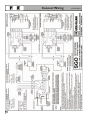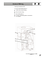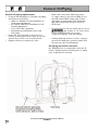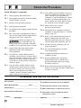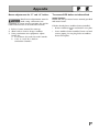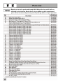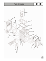
1
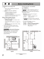
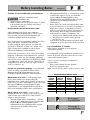
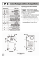
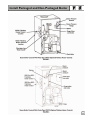
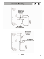
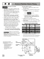
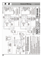
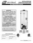
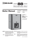
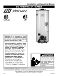
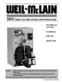
SGO SERIES 3 OIL-FIRED NATURAL DRAFT STEAM BOILER
This Manual
Includes:
Installation
Start-Up
Boiler Parts
Installer: • Make sure this is the correct manual for the boiler. Verify boiler model on
rating label.
• Leave all documentation received with boiler and burner with unit for
future reference.
User: Boiler and burner must be installed and serviced by qualified service technician.
Part No. 550-141-829/1201
Read This Page First
Hazard Definitions
The following terms are used to bring attention to the presence of hazards of various risk levels or to
important information concerning product life.
Indicates presence of hazards that will cause severe personal injury, death or substantial
property damage if ignored.
Indicates presence of hazards that can cause severe personal injury, death or substantial
property damage if ignored.
Indicates presence of hazards that will or can cause minor personal injury or property
damage if ignored.
Indicates special instructions on installation, operation, or maintenance that are
important but not related to personal injury hazards.
Symbol Definitions
The following symbols are used to indicate sequence of installation for:
Factory-assembled packaged boiler—block, jacket and controls. Sizes 3
through 6 only.
Factory-assembled block, no burner. Sizes 3 through 6 with jacket installed; steam trim controls
shipped separately. Sizes 7 through 9 with jacket and steam trim controls shipped separately.
When Calling or Writing About the Boiler
Please have boiler model number and series from boiler rating label and CP number(s) from boiler jacket,
burner and controls. On page 26 of this manual is space to list CP number(s).
2
Table of Contents
Read all instructions before installing. Failure to follow all instructions in proper order
can cause severe personal injury, death or substantial property damage.
Read This Page First . . . . . . . . . . . . . . . . . . . . . . . . .2
Table of Contents . . . . . . . . . . . . . . . . . . . . . . . . . . .3
Before Installing Boiler . . . . . . . . . . . . . . . . . . . . . .4-5
Install Packaged Boiler . . . . . . . . . . . . . . . . . . . . . . .6-7
Install Non-Packaged Boiler . . . . . . . . . . . . . . . . . . .7-11
Connect Breeching . . . . . . . . . . . . . . . . . . . . . . . . . .12-13
Connect Steam Piping . . . . . . . . . . . . . . . . . . . . . . .14-17
Connect Tankless Heater Piping . . . . . . . . . . . . . . .18
Connect Wiring . . . . . . . . . . . . . . . . . . . . . . . . . . . .19-23
Connect Oil Piping . . . . . . . . . . . . . . . . . . . . . . . . . .24
Start-Up . . . . . . . . . . . . . . . . . . . . . . . . . . . . . . . . . .25
Check-Out Procedure . . . . . . . . . . . . . . . . . . . . . . .26
Installation and Service Certificate . . . . . . . . . . . . .26
Appendix . . . . . . . . . . . . . . . . . . . . . . . . . . . . . . . . .27
Parts List . . . . . . . . . . . . . . . . . . . . . . . . . . . . . . . . .28
Parts Drawing . . . . . . . . . . . . . . . . . . . . . . . . . . . . . .29
Dimensions . . . . . . . . . . . . . . . . . . . . . . . . . . . . . . . .30-31
Ratings . . . . . . . . . . . . . . . . . . . . . . . . . . . . . . . . . . .Back Cover
3
Before Installing Boiler
Installations must comply with:
•
U.S.
— State and local plumbing, heating and
electrical codes.
— National codes where applicable.
Canada
— Canadian Standards Association,
CSA B139, Installation Code for
Oil-Burning Equipment.
— CSA C22.1 Canadian Electrical Code Part One.
— Applicable local or provincial codes.
•
Provide clearances around boiler
(see FIGURE 1):
Jacket cap must be in place on
boiler to avoid requiring an 18"
minimum clearance from back or top of boiler to
combustible material.
•
Before selecting boiler location:
•
Check for nearby connections to:
— System water piping.
— Chimney. See pages 12-13. Boiler can be
top or back vented.
— Combustion and ventilation air supply. See
page 5.
— Oil supply. See page 24 for oil line routing.
— Electrical power.
Check area around boiler. Remove any
combustible materials, gasoline and other
flammable liquids.
•
Minimum clearances from vent pipe to
combustible material:
6 inches — Type “L” doublewall vent*
18 inches — Singlewall vent*
Flue pipe clearances must take
precedence over jacket clearances.
•
Recommended service clearances:
24 inches — Front and top
6 inches — Left side**, back and right side Δ
15 inches — Left side with tankless heater**
12 inches — Right side for burner door
swing radius Δ
Failure to keep boiler area
clear and free of combustible
materials, gasoline and other flammable
liquids and vapors can result in severe
personal injury, death or substantial
property damage.
4
Recommended Service Clearances
FIGURE 1
Before Installing Boiler
Provide air for combustion and ventilation:
Adequate combustion and
ventilation air:
• Assures proper combustion.
• Reduces risk of severe personal injury or death
from possible flue gas leakage and carbon
monoxide emissions.
Do not install exhaust fan in boiler room.
Older buildings with single-pane windows,
minimal weather-stripping and no vapor barrier
often provide enough natural infiltration and
ventilation without dedicated openings.
New construction or remodeled buildings are most
often built tighter. Windows and doors are
weather-stripped, vapor barriers are used and
openings in walls are caulked. As a result, such
tight construction is unlikely to allow proper
natural air infiltration and ventilation.
Follow state, provincial or local codes when sizing
adequate combustion and ventilation air openings.
In absence of codes, use the following guidelines
when boiler is in a confined room (defined by NFPA
31 as less than 7200 cubic feet per 1 GPH input of
all appliances in area. A room 8 ft. high x 33.5 ft. x
33.5 ft. is 7200 cu. ft.):
Provide two permanent openings — one within 12
inches of ceiling, one within 12 inches of floor.
Minimum height or length dimension of each
rectangular opening should be at least 3 inches.
When inside air is used — each opening must
freely connect with areas having adequate
infiltration from outside. Each opening should be at
least 140 sq. in. per 1 GPH input (1 sq. in. per 1000
Btu input) of all fuel-burning appliances plus
requirements for any equipment that can pull air
from room (including clothes dryer and fireplace).
When outside air is used — connect each
opening directly or by ducts to the outdoors or to
crawl or attic space that freely connects with
outdoors. Size per below:
• Through outside wall or vertical ducts — at least
35 sq. in. per 1 GPH input (1 sq. in. per 4000 Btu
input) of all fuel burning appliances plus
requirements for any equipment that can pull
air from room (including clothes dryer
and fireplace).
•
•
CONTINUED
Through horizontal ducts — at least 70 sq. in. per
1 GPH boiler input (1 sq. in. per 2000 Btu
input) of all fuel-burning appliances plus
requirements for any equipment that can pull
air from room (including clothes dryer
and fireplace).
Where ducts are used, they should have same
cross-sectional area as free area of openings to
which they connect. Compensate for louver,
grille or screen blockage when calculating free
air openings. Refer to their manufacturer’s
instructions for details. If unknown, use:
— Wood louvers, which provide 20-25% free air.
— Metal louvers or grilles, which provide
60-75% free air.
Lock louvers in open position or interlock with
equipment to prove open before boiler operation.
Lay a foundation, if needed:
Boiler may be installed on non-carpeted
combustible flooring.
For residential garage installation, install boiler so
burner is at least 18 inches above floor to avoid
contact with gasoline fumes.
A level concrete or masonry foundation is
required when:
• Floor could possibly become flooded.
• Non-level conditions exist.
Solid concrete blocks can be used to create a pad.
BOILER FOUNDATION SIZE TABLE
BOILER
MODEL
SGO-3
SGO-4
SGO-5
SGO-6
SGO-7
SGO-8
SGO-9
LENGTH
INCHES
17
20
23
26
29
32
35
WIDTH
INCHES
22
22
22
22
22
22
22
MIN.
HEIGHT
INCHES
2
2
2
2
2
2
2
Go to page 6
to install boiler
Go to page 7
to install boiler
5
Install Packaged Boiler
Place boiler:
Tankless heater, if used:
1. Remove boiler from pallet.
1. Remove tankless heater knockout in left side of
jacket panel and, for SGO-6 only, tankless
heater control knockout.
2. Remove tankless heater cover plate and gasket.
3. Install new gasket and tankless heater over
studs around opening. Secure with 3/8" nuts.
4. Install tankless heater operating control
where shown on page 18. If not furnished,
use operating control with maximum
10°F differential.
Do not drop boiler or bump
jacket on floor or pallet.
Damage to boiler can result.
Smaller sized boilers may be
top heavy. Use caution when
handling to avoid minor personal injury or
property damage.
2. Boiler is shipped for back flue outlet. To
change to top flue outlet (see FIGURE 2):
a. Remove jacket cap on top of boiler.
b. Loosen two screws holding flue cap strap
to collector hood. Remove strap and flue
cap from opening. Re-tighten screws.
c. Check rope placement inside flue cap.
(Read
under step #5 below).
d. Loosen two screws on back flue outlet. Set
flue cap on outlet. Install strap by engaging
slots in screws. Tighten screws. Make sure
cap is securely installed.
e. Snap jacket cap in back outlet opening.
Jacket cap must be in place
on boiler to avoid requiring
an 18" minimum clearance from back of
boiler to combustible material.
3. Check level. Shim legs, if needed.
4. Check for secure placement of insulation on
target wall, chamber floor and burner door.
5. Visually check:
a. Flue collector hood seal.
b. Burner mounting door seal.
Obtain gas-tight seal to
prevent possible flue gas
leakage and carbon monoxide emissions,
which can lead to severe personal injury
or death.
Perform hydrostatic pressure test:
1. Remove steam pressure gauge furnished with
boiler. Install water pressure gauge for test
only. Be sure gauge can handle test pressure.
2. Install air vent in tapping on top of boiler.
3. Remove pressure control and low water cutoff.
Plug tappings.
4. Plug supply and return tappings.
5. Drain valve is already factory-installed.
6. Fill boiler. Vent all air. Pressure test boiler at
45-55 psig.
Do not leave boiler unattended.
Cold water fill can expand and
damage cast iron, resulting in severe personal
injury, death or substantial property damage.
7. Check for maintained gauge pressure for more
than 10 minutes. Visually check for leaks if
gauge pressure drops.
8. Drain boiler. Repair leaks if found.
Using petroleum-based
compounds to repair leaks can
damage system components, resulting in
property damage.
9. Retest boiler after repairing leaks.
10. Remove pressure gauge, air vent and plugs.
Re-install steam pressure gauge, pressure control
and low water cutoff furnished with boiler.
Go to page 12 to connect
breeching and venting
6
Install Packaged Boiler
CONTINUED
Change From Back Flue Outlet to Top Flue Outlet (Optional)
FIGURE 2
Install Non-Packaged Boiler
Fiberglass wool and ceramic fiber materials:
• POSSIBLE CANCER HAZARD
BY INHALATION
• CAN CAUSE RESPIRATORY,
SKIN AND EYE IRRITATION
This product contains fiberglass wool and ceramic
fiber materials. Airborne fibers from these materials
have been listed by the State of California as a
possible cause of cancer through inhalation. Apply
special care when handling ceramic fiber (chamber
lining and base insulation) materials. Ceramic fibers
can be converted to chrystobalites, a substance listed
as a probable cause of cancer.
Suppliers of fiberglass wool products recommend
the following precautions be taken when handling
these materials:
Precautionary measures:
• Avoid breathing fiberglass dust and contact
with skin and eyes.
• Use NIOSH approved dust/mist respirator.
• Wear long-sleeved, loose fitting clothing, gloves
and eye protection.
• Wash work clothes separately from other
clothing. Rinse washer thoroughly.
• Operations such as sawing, blowing, tearout
and spraying may generate airborne fiber
concentration requiring additional protection.
First aid measures:
• Eye contact — Flush eyes with water to
remove dust. If symptoms persist, seek
medical attention.
• Skin contact — Wash affected areas gently
with soap and warm water after handling.
7
Install Non-Packaged Boiler
Place boiler:
1. Non-Packaged SGO-3 through 6 — position on site.
Smaller sized boilers may be
top heavy. Use caution when
handling to avoid minor personal injury or
property damage.
a. Boiler is shipped for back flue outlet. To
change to top flue outlet (see FIGURE 3):
1) Loosen two screws holding flue cap strap
to collector hood. Remove strap and flue
cap from opening. Re-tighten screws.
2) Check rope placement inside flue cap.
(Read
under step #3 at right).
3) Loosen two screws on back flue outlet.
Set flue cap on outlet. Install strap by
engaging slots in screws. Tighten screws.
Make sure cap is securely installed.
2. Non-Packaged SGO-7, 8 & 9 — split the
assembled block for easier handling (see
FIGURE 3):
a. Open burner mounting door and using
utility knife, slit floor insulation at joint to
be separated.
b. Remove 5½" draw rod and the longest draw
rod from each side. Pull block apart. Save
draw rods, nuts, washers and sealing rings
for reassembly.
c. Move divided block to location.
d. Clean port openings with clean rag.
Do not use petroleum-based
compounds to clean
openings. Damage to system components
can result causing property damage.
e. Place rings in port openings. If ring slips
out of groove, stretch ring gently for several
seconds, then place in groove.
f. Position sections so aligning lugs fit into
sockets of next section. Make sure sealing
rope is in good condition and in position.
g. Oil threads on draw rods. Install
washer and nut on end to be tightened.
Use nut only on other end.
8
CONTINUED
h. With wrench at washer/nut end, uniformly
tighten nuts starting with 5½" rod at large port,
5½" rod at small port, bottom long rod and
finally top long rod.
i. Torque on both 5½" rods and bottom long
rod should be 50-60 ft. lbs; long top rod
should be 20-25 ft. lbs. Do not
back-off nuts.
j. Metal-to-metal contact should be made
around port openings. If gap does exist, it
should be less than .020". Check with
feeler gauge.
k. If gap around port openings exceeds .020",
check for dirt on port openings, sockets or
misaligned lugs. If corrections are made
and gap still exists, contact your WeilMcLain distributor or sales office before
continuing installation.
3. Non-Packaged SGO-7, 8 & 9 — install flue
collector hood (see FIGURE 3):
Obtain gas-tight seal to prevent
possible flue gas leakage and
carbon monoxide emissions, leading to severe
personal injury or death.
a. Thread tinnerman clip on screw so that clip
fits snugly in notch of hold-down lug. Screw
must not turn.
b. Remove paper on sealing rope. Starting at
back section near flue collar, position sealing
rope around top of block with adhesive side
to sections. Do not stretch rope. Make sure
rope ends meet. Trim excess rope.
c. Position flue collector hood on top of boiler
sections and over screws and clips as
shown in FIGURE 3.
d. Install washers and nuts. Tighten nuts
until collector hood makes contact with
tinnerman clip.
e. Back flue outlet boiler — Position flue cap
and strap over opening in flue collector
hood. Make sure rope in cap is in place
and in good condition. Tighten strap to
hood with screws provided.
Top flue outlet boiler — Position flue cap
and strap over opening in back section.
Make sure rope in cap is in place and in
good condition. Tighten strap to boiler with
screws provided in section. Install remaining
screws in holes in flue collector hood.
4. Check level. Shim legs, if needed.
Install Non-Packaged Boiler
CONTINUED
Install Packaged and Non-Packaged Boiler
Install burner (also refer to instructions
packed with burner):
Burners designed for use with
Weil-McLain 68 boilers must not be
used on GOLD Oil boilers. Contact individual burner
manufacturers for GOLD Oil applications.
For P-SGO and A-SGO boiler:
1. Secure universal mounting flange and gasket to
burner mounting door. Use three bolts provided.
2. Secure burner on flange with three bolts.
3. Position burner so end of air tube is level to
1½° tilt down toward chamber. Open door to
verify burner position. End of air tube should be
flush to ¼" recessed from inside wall of burner
door refractory. Check for secure placement of
insulation on target wall, chamber floor and
burner mounting door. Securely close door.
Install Packaged and Non-Packaged Boiler
Connect Breeching
General chimney requirements:
•
Designed for natural draft firing. Connect
boiler to vertical chimney.
Insufficient draft can cause flue
gas leakage and carbon
monoxide emissions, which will lead to severe
personal injury or death.
•
•
Use vent material approved by local codes for
oil-fired burners. In their absence, refer to:
— NFPA 31, Installation of Oil-Burning Equipment.
— NFPA 211, Standard for Chimneys,
Fireplaces, Vents and Solid Fuel
Burning Appliances.
— In Canada, refer to CSA B139, Installation
Code for Oil-Burning Equipment.
NFPA 211 requires chimney to be lined before
connected to boiler.
Inspect existing chimney before
installing new boiler. Failure to
do any of the following will result in severe
personal injury or death:
— Clean chimney, including removal of blockage.
— Repair or replace damaged pipe or liner.
— Repair mortar and joints.
To prevent downdrafts, extend chimney at
least 3 feet above highest point where it passes
through roof and 2 feet higher than any
portion of building within 10 feet. Increase
chimney cross-sectional area and height at
least 4% per 1,000 feet above sea level.
•
•
Minimum clearances from vent pipe to
combustible material:
6 inches — Type “L” doublewall vent
18 inches — Singlewall vent
Minimum chimney sizes should be used.
Oversized chimneys, outside
masonry chimneys and/or
derated inputs can result in condensation
in chimney.
Connect breeching:
Long horizontal breechings,
excessive number of tees and
12
MINIMUM CHIMNEY SIZE TABLE
***
BOILER
MINIMUM
MODEL BREECHING
NUMBER DIAMETER
SGO-3
SGO-4
5"
6"
SGO-5
6"
SGO-6
7"
SGO-7
SGO-8
SGO-9
7"
MINIMUM
I=B=R
CHIMNEY SIZE
RECT. ROUND
MINIMUM
CHIMNEY
HEIGHT
8" x 8"
*
6"
15'
8" x 8"
*
7"
15'
8" x 12"
**
7"
20'
*
6¾" x 6¾" inside liner
* * 6½" x 10½" inside liner
* * * Flue collar on boiler is 7" diameter
elbows, or other obstructions restricting combustion
gas flow can result in possibility of condensation,
flue gas leakage and carbon monoxide emissions,
which can lead to severe personal injury or death.
1. Install 2 flue pipe brackets.
2. Connect full-sized breeching when possible.
See Minimum Chimney Size Table.
— Back outlet — see FIGURE 7.
— Top outlet — see FIGURE 8.
3. Connection must be made above bottom of
chimney to avoid blockage. Breeching must not
enter chimney far enough to cause obstruction.
Use thimble or slip joint where breeching enters
chimney to allow removal for cleaning.
4. When burner and boiler are properly installed,
draft overfire will be approximately -0.01"
to -0.02" W.C. Install barometric control in
breeching, per control manufacturer's
instructions, when excess draft needs to be
relieved or to comply with applicable codes
and regulations. Use draft gauge to adjust
proper opening.
5. An induced draft fan for the chimney may be
necessary if:
— Excessive resistance to flow of combustion
gases can be expected.
— Cross-sectional area of chimney is smaller
than minimum recommended.
— Chimney height is less than recommended.
Seal all vent joints. Interlock burner with
fan operation.
Connect Breeching
CONTINUED
Back Outlet Breeching Connection
FIGURE 7
Top Outlet Breeching Connection
FIGURE 8
13
Connect Steam Piping
General piping information:
•
•
•
•
•
Hartford Loop piping arrangement and wet
return are required for steam boilers.
Maintain 24-inch minimum from waterline to
bottom of header (minimum 50 7/8" from floor
or top of foundation).
When using condensate receiver, feed pump
must be energized by boiler-mounted
pump control.
Use swing joints in steam piping.
If installation is to comply with ASME or
Canadian requirements, an additional pressure
limit control is needed. Install control between
existing pressure control and pressure gauge.
Control must be installed with siphon
(supplied with boiler) between control and
boiler. Set control to minimum of 5 psi above
setpoint of existing control and maximum
setting of 15 psi. Wire as shown on boiler
wiring diagram.
3. Float-type low water cutoff only — install
blowdown line in bottom of cutoff. See
FIGURE 9 or 10 and also refer to low water
cutoff manufacturer’s instructions for details.
Pipe blowdown line near floor
close to floor drain to eliminate
potential of severe burns. Do not pipe to any
area where freezing could occur. Do not plug,
valve or place any obstruction in discharge line.
STEAM PIPING SIZE TABLE
FOR ONE AND TWO-PIPE SYSTEMS
A
B
HEADER
PIPE
SIZE
“H” * *
SGO-3
2½"
—
2½"
1½"
SGO-4
2½"
—
2½"
1½"
Install piping:
SGO-5
2½"
—
3"
1½"
1. See Tables at right and FIGURE 9 on page 15
or FIGURE 10 on page 16.
SGO-6
2½"
2½"
3"
1½"
SGO-7
2½"
2½"
3"
1½"
SGO-8
2½"
2½"
3"
1½"
SGO-9
2½"
2½"
3"
1½"
BOILER
MODEL
NUMBER
Improperly piped systems or
undersized piping can
contribute to erratic boiler operation and
possible boiler or system damage. Piping
system must be installed as shown, using
minimum pipe sizes shown. Consult your
Weil-McLain distributor or sales office before
installing alternate piping.
EQUALIZER
PIPE SIZE
“J”
STEAM PIPING SIZE TABLE
FOR ONE-PIPE COUNTERFLOW SYSTEMS
A
B
HEADER
PIPE
SIZE
“H” * *
SGO-3
2½"
—
2½"
1½"
SGO-4
2½"
—
2½"
1½"
SGO-5
2½"
—
3"
1½"
SGO-6
2½"
2½"
4"
1½"
SGO-7
2½"
2½"
4"
1½"
SGO-8
2½"
2½"
4"
1½"
SGO-9
2½"
2½"
4"
1½"
BOILER
MODEL
NUMBER
2. Install relief valve vertically in “R” tapping on
back of boiler. See FIGURE 9 or 10 and also
refer to tag attached to relief valve for
manufacturer’s instructions.
Pipe relief valve discharge line
near floor close to floor drain to
eliminate potential of severe burns. Do not
pipe to any area where freezing could occur.
Do not plug, valve or place any obstruction in
discharge line.
14
RISER
PIPE SIZE *
RISER
PIPE SIZE *
EQUALIZER
PIPE SIZE
“J”
*
Based on ASHRAE Fundamentals Handbook recommendations, allowing
½ oz. pressure drop at 0 psig.
**
Based on ASHRAE Fundamentals Handbook recommendations, allowing
2 oz. pressure drop per 100 feet of pipe at 3.5 psig. Maintain minimum
24" height from waterline to bottom of header.
Can be reduced to 2".
Connect Steam Piping
CONTINUED
Connect Steam Piping
CONTINUED
Connect Steam Piping
CONTINUED
To size and install reservoir piping, see FIGURE 11
and Bulletin AE-8403 (available through your
Weil-McLain distributor or sales office):
Optional reservoir piping:
Modern steam boilers are designed to steam for
less time than older, larger boilers. When replacing
an older steam boiler, the system condensate
return time may be longer than the steaming time.
This can cause the following problems:
• Boilers fitted with an automatic water feed
could overfill.
• Units fitted with only a low water cutoff would
shut down and cycle while waiting for
condensate to return.
1. Pipe boiler as shown on pages 14 through 16.
2. Use 8" diameter reservoir pipe.
3. Locate centerline of reservoir pipe 1" below
26 7/8 " boiler waterline.
CONDENSATE RECEIVER CAPACITY TABLE
MINIMUM CONDENSATE RECEIVER CAPACITY – GAL.
BOILER
MODEL
SGO-3
SGO-4
SGO-5
SGO-6
SGO-7
SGO-8
SGO-9
I=B=R GROSS
OUTPUT
LBS STEAM
PER HOUR
GALLONS
CONDENSATE
PER HOUR
15 MIN.*
BOILER
OPERATION
114
150
180
216
246
274
303
14
18
22
26
30
33
36
4
5
6
8
9
10
11
* Maximum time to when condensate returns to boiler.
30 MIN.*
BOILER
OPERATION
8
11
13
16
18
20
22
45 MIN.*
BOILER
OPERATION
12
16
19
23
27
30
33
60 MIN.*
BOILER
OPERATION
RECOMMENDED
CONDENSATE
FEED PUMPING RATE
GPM
AT 15 PSI
16
22
26
31
35
39
44
0.5
0.6
0.7
0.9
1.0
1.1
1.2
Connect Tankless Heater Piping
Hot Water Can Scald!
•
•
•
•
Consumer Product Safety Commission and
some states recommend domestic hot water
temperature of 130°F or less.
When installing an automatic mixing valve,
selection and installation must comply with
valve manufacturer’s recommendations
and instructions.
Water heated to a temperature suitable for
clothes washing, dish washing and other
sanitizing needs will scald and cause injury.
Children and elderly, infirm or physically
handicapped persons are more likely to be
injured by hot water. Never leave them
unattended in or near a bathtub, shower or
sink. Never allow small children to use a hot
water faucet or draw their own bath. If anyone
using hot water in the building fits this
description, or if state laws or local codes
require certain water temperatures at hot
water faucets, take special precautions:
— Install automatic mixing valve set
according to those standards.
— Use lowest practical temperature setting.
— Check water temperature immediately after
first heating cycle and after any adjustment.
Studies have indicated that
dangerous bacteria can form in
potable water distribution systems if certain
minimum water temperatures are not
maintained. Contact local health department
for more information.
To pipe tankless heater:
1. Size piping no smaller than tankless heater
inlet and outlet.
2. Following controls (furnished by others) must
be installed:
a. Automatic mixing valve. See FIGURE 12.
(Read
at left.)
b. Flow regulating valve. Size according to
intermittent draw of tankless heater. See
Table below. Follow valve manufacturer’s
instructions to install.
3. Additional anti-scald devices may be
installed at each hot water faucet, bath and
shower outlet.
4. In hard water areas, soften cold domestic supply
water to heaters to prevent lime build-up.
TANKLESS HEATER RATINGS TABLE
BOILER
INTERMITTENT
INLET
MODEL
HEATER DRAW RATINGS AND OUTLET
NUMBER * NUMBER
(GPM) * *
TAPPING SIZES
SGO-3
SGO-4
SGO-5
SGO-6
SGO-7
SGO-8
SGO-9
*
**
35-S-29
35-S-29
35-S-29
35-S-29
35-S-29
35-S-29
35-S-29
3.25
3.50
3.75
4.00
4.00
4.00
4.00
¾"
¾"
¾"
¾"
¾"
¾"
¾"
To avoid supplying steam to system during summer tankless operation,
raise water level to one inch above normal water line.
Gallons of water per minute heated from 40°F to 140°F with 200°F
boiler water temperature. Tested in accordance with I=W=H Testing and
Rating Standard for Indirect Tankless Water Heaters Tested with Boilers.
Connect Wiring
General wiring requirements:
Junction box (furnished):
•
Electric shock hazard. Can cause
severe personal injury or death if
power source, including service switch on boiler, is
not disconnected before installing or servicing.
•
•
•
•
•
•
Installations must follow these codes:
— National Electrical Code, ANSI/NFPA 70,
latest edition and any additional national,
state or local codes.
— In Canada, CSA C22.1 Canadian Electrical
Code Part One and any local codes.
Wiring must be N.E.C. Class 1. If original wire
as supplied with boiler must be replaced, type
105°C wire or equivalent must be used. Supply
wiring to boiler and additional control wiring
must be 14 ga. or heavier.
Provide electrical ground at boiler as required
by codes.
•
•
•
Burner wiring:
•
Thermostat wiring:
•
•
Install thermostat on inside wall away from
influences of drafts, hot or cold water pipes,
lighting fixtures, television, sun rays or
fireplaces.
Follow instructions with thermostat. If it has a
heat anticipator, set heat anticipator in
thermostat to match power requirements of
equipment connected to it. Boiler wiring
diagrams give setting for standard equipment.
Junction box houses electrical connections for
all boiler components.
“P” boilers have harnesses furnished.
“A” boilers are furnished with burner and limit
harnesses.
All field-provided high voltage wiring must be
sheathed in flexible metal conduit.
Connect incoming line voltage “HOT” wire to
service switch, and neutral wire to white wire.
Field-install equipment ground wire to green
wire with wire nut.
Service switch (15 amp) is provided with boiler.
“A” boilers — install switch as shown.
Some local codes may require an emergency
shut-off switch installed at a location away
from boiler. Follow local codes.
•
•
Burner harness incorporates a disconnect
plug, providing a convenient way to disconnect
wiring when burner mounting door is opened.
All “P” boilers have a power disconnect plug
installed on burner.
On “A” boilers, mount the plug (provided in
steam trim carton) on the burner housing as
shown in FIGURE 13 or 14. For Carlin
burners, screw burner plug into threaded
conduit coupling, then mount this assembly to
the burner housing using the chase nipple.
Route wires through housing and make
connections in burner junction box as shown
in boiler wiring diagram.
To wire boilers, refer to the following pages:
Pages 20 to 21 Float-Type LWCO
Pages 22 to 23 Probe-Type LWCO
19
Connect Wiring
20
CONTINUED
Connect Wiring
Float-Type Low Water Cutoff
1
Pressure Control Wiring Harness
2
Tankless Heater Control Wiring
3
Burner Disconnect Plug
4
Burner Wiring Harness
5
Low Water Cutoff Wiring Harness
not furnished on “A” Boilers
Boiler Wiring for Float-Type LWCO
FIGURE 13
21
Connect Wiring
22
CONTINUED
Connect Wiring
Probe-Type Low Water Cutoff
1
Pressure Control Wiring Harness
2
Tankless Heater Control Wiring
3
Burner Disconnect Plug
4
Burner Wiring Harness
5
Low Water Cutoff Wiring Harness not furnished
on “A” Boilers
Boiler Wiring for Probe-Type LWCO
FIGURE 14
23
Connect Oil Piping
General oil piping requirements:
•
•
•
Location and installation of oil tanks, oil piping
and burners must follow:
— NFPA 31, Standard for the Installation of
Oil-Burning Equipment.
— In Canada, CSA B139, Installation of OilBurning Equipment.
— Local codes and regulations.
— Information provided with burner and
fuel pump.
If any part of fuel oil tank is above level of
burner, an anti-siphon device must be used to
prevent flow of oil in case of oil line break.
Support oil lines as required by codes.
•
Make tank connections with swing joints
or copper tubing to prevent breaking in case
the tank settles. Make swing joints so they
will tighten as tank settles. Non-hardening
pipe joint compounds should be used on
all threads.
•
Do not use Teflon tape as an oil
pipe sealant. It can cause valves
to fail, creating hazards. Do not use
compression fittings, only flare fittings.
•
Underground pipe must be run in a casing to
prevent oil leaking into ground or under floor.
Check local codes for information.
Oil piping connection at burner:
See FIGURE 15 for recommended connection at
burner, allowing burner mounting door to swing
open completely for servicing.
24
Recommended Oil Piping Connection to Burner
FIGURE 15
Start-Up
Follow information below to prevent
severe personal injury, death or
substantial property damage:
• Do not use gasoline crankcase drainings or
any oil containing gasoline. See burner manual
for proper fuel oil.
• Do not attempt to start burner when excess oil
has accumulated, when unit is full of vapor or
when combustion chamber is very hot.
• Do not start burner unless collector hood, flue
cap, jacket cap, breeching and burner
mounting door are secured in place.
• Never burn garbage or paper in the boiler.
• Never leave combustible material around it.
Fill the system:
1. Do not fill (except for leakage tests) until boiler
is ready to be fired.
2. Fill to normal water line as indicated on jacket
front panel.
3. Boiler water pH 7.0 to 8.5 is recommended.
Failure to maintain
recommended pH level can
cause section failure and leaks.
4. Follow "Skim steam boiler" to assure
proper operation.
Tips for steam systems:
•
Check boiler and system piping for leaks.
Continual makeup water will reduce boiler life.
Minerals can build up in sections, reducing
heat transfer and causing cast iron to
overheat, resulting in section failure.
Failure to maintain
recommended pH and repair
leaks can cause section iron corrosion, leading
to section failure and leaks. Do not use
petroleum-based sealing or stop-leak
compounds in boiler system. Damage to system
components can result.
•
For pH conditions outside 7.0 to 8.5 range or
unusually hard water areas (above 7 grains
hardness), consult local water treatment company.
Skim steam boiler:
Clean new steam boilers to remove
any impurities. Failure to properly
clean can result in violent water level fluctuations,
water passing into steam mains, or high
maintenance costs on strainers, traps or vents.
Skim boiler only. Do not clean old piping or leaks
can occur.
Do not use petroleum-based
compounds in boiler system.
Damage to system components can result,
causing property damage.
1. Provide 1½ " skim piping from skim tapping to
floor drain. Add a tee in piping to observe skim
water level. Raise waterline to midpoint of
skim tapping.
2. Fire burner to maintain water temperature below
steaming temperature during skimming process.
3. Feed in water to maintain water level. Cycle
burner to prevent rise in steam pressure.
Continue skimming until discharge is clear.
4. While boiler is warm, but not hot, drain boiler
through drain valve.
5. Remove skim piping. Close drain valve. Fill
with fresh water to normal waterline. Start
burner and steam for 15 minutes to remove
dissolved gases. Stop burner.
6. Check traps and air vents for proper operation.
7. Process may need to be repeated after several
weeks of operation.
To place in operation:
1. Verify boiler is filled with water to normal
waterline as indicated on jacket front panel.
2. Open burner door and verify rear target wall,
floor and burner door insulations are in proper
position and condition.
3. Verify burner mounting door is closed tightly
and burner wiring harness is connected to
junction box.
4. Factory burner adjustment and settings may not
be suitable for specific job conditions. See
Appendix, page 27.
Make final burner adjustments
using combustion test equipment
to assure proper operation. Do not fire boiler
without water. Sections will overheat, damaging
boiler and resulting in substantial property damage.
5. Check boiler and system piping for leaks.
See “Tips for steam systems.”
6. Inspect breeching and venting for
proper operation.
For additional information, refer to
instructions packed with boiler or burner:
• Burner Manual
• Maintenance and Service Guide for
GOLD Oil Steam Boilers
25
Check-Out Procedure
Check off steps as completed:
❑
❑
❑
❑
❑
❑
❑
❑
❑
❑
1. Boiler properly filled with water?
2. Boiler piping checked for leaks (including
tankless heater, if used)?
3. System vents operating properly?
4. Boiler properly skimmed?
❑
5. Air purged from oil piping? Piping checked
for leaks?
❑
6. Flue cap in place and tightened? Burner
door closed, sealed and nut tight? Burner
plugged in and service switch on?
❑
Obtain gas-tight seal to
prevent possible flue gas
leakage and carbon monoxide emissions,
leading to severe personal injury or death.
❑
7. Proper draft and burner flame? Final
adjustment made with combustion
test equipment?
8. Test pressure control: While burner is
operating, move indicator on limit control
below actual boiler steam pressure. Burner
should go off. Raise setting on pressure
control above steam pressure and burner
should re-ignite.
9. Test low water cutoff(s): Follow control
manufacturer’s instructions for testing
procedures. Make sure burner goes off
when control responds to low water
condition. Burner should re-ignite when
proper water level is restored.
❑
❑
❑
❑
10. Test additional field-installed controls: If
boiler has additional operating control or
other controls, test for operation as
outlined by control manufacturer. Burner
should be operating and should go off
when controls are tested. When controls
are restored, burner should re-ignite.
11. Limit control set to system
pressure requirements?
12. Thermostat heat anticipator setting (if
available) set properly? Refer to “Connect
wiring,” page 19.
13. Boiler cycled with thermostat? Raise to
highest setting and verify boiler goes
through normal start-up cycle. Lower to
lowest setting and verify boiler goes off.
14. Observed several operating cycles for
proper operation?
15. Set room thermostat(s) to desired
room temperature?
16. Completed Installation and Service
Certificate below?
17. Reviewed Maintenance and Service
Manual with owner or maintenance
person and instructed person to keep
for future reference?
18. Returned all instructions provided with
boiler to its envelope and placed with boiler
for future reference?
Installation and Service Certificate
Date Installed: ______________________________________________
❏
Installation instructions have been followed.
Boiler Model Number: __________________Series: _________
❏
Check-out procedure has been performed.
CP Number(s):______________________________________________
❏
Above information is certified to be correct.
Measured Btu or GPH Input: _____________________________
❏
Information received and left with owner/
maintenance person.
Installer:__________________________________________________________________________________________________________________________
(Company)
(Address)
(Phone)
26
_________________________________________________________________
(Installer’s Signature)
Appendix
Burner adjustments for “P” and “A” boilers:
Final burner adjustments must be
made using combustion test
equipment to assure proper operation. Do not fire
boiler without water or sections will overheat.
1. Refer to burner manual for start-up.
2. Allow boiler to heat to design condition.
3. Using combustion test equipment, adjust
burner for:
a. CO2 between 11% and 12% and 0 smoke.
b. -0.01" to -0.02" W.C. draft in
combustion chamber.
To connect SGO boilers to indirect-fired
water heaters:
Install and wire per water heater manual provided
with water heater.
If boiler already has a tankless heater installed:
• Remove tankless heater and install cover plate.
OR
• Leave tankless heater installed. Drain coil and
remove piping. Do not plug holes in tankless
heater front plate.
27
Parts List
Repair parts must be purchased through Weil-McLain for the specific boiler as
indicated in the list below. Results from using modified or other manufactured
parts will not be covered by warranty and may damage boiler or impair operation.
Parts Drawing
Dimensions
DIMENSIONS - in.
BOILER
MODEL
NUMBER
A
B
L
SGO-3
—
131/2
16 7/8
SGO-4
—
165/8
20
SGO-5
—
197/8
221/ 8
SGO-6
19
231/2
261/ 4
SGO-7
22 1/8
261/8
29 3/8
SGO-8
25 1/4
291/4
32 1/2
SGO-9
28 3/8
323/8
35 5/8
DIMENSIONS - mm.
BOILER
MODEL
NUMBER
A
B
L
SGO-3
—
342.9
428.7
SGO-4
—
422.1
508.0
SGO-5
—
504.9
587.2
SGO-6
482.6
584.2
666.7
SGO-7
561.8
663.4
746.2
SGO-8
641.4
742.9
825.5
SGO-9
720.9
822.4
904.7
30
Dimensions
CONTINUED