1
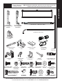
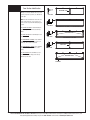
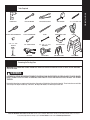
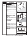
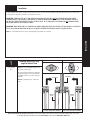
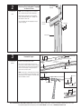
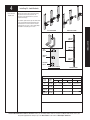
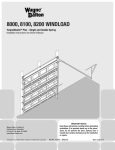
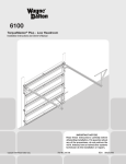
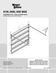
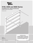
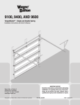
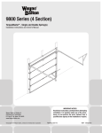
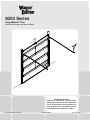
9300 Series
TorqueMaster® Plus
Installation Instructions and Owner’s Manual
IMPORTANT NOTICE!
Read these instructions carefully before
attempting installation. If in question about
any of the procedures, do not perform the
work. Instead, have a trained door systems
technician do the installation or repairs.
Copyright 2008 Wayne-Dalton Corp.
Part No. 327882
Rev 2 3-28-2008
Table of Contents
Important Safety Instructions .................................................. 2
Package Contents ................................................................... 3
Door Section Identification ...................................................... 4
Tools Required ........................................................................ 5
Pre-Installation ....................................................................3-6
Removing An Existing Door ..................................... 5
Preparing The Opening ........................................... 6
Installation ........................................................................7-22
Torquemaster Plus Reset Instructions...............................23-25
Optional Installations .......................................................25-26
Side Lock ............................................................. 25
Pull Rope .............................................................. 26
Trolley Operator .................................................... 26
Maintenance ......................................................................... 26
Cleaning ............................................................... 26
Warranty ............................................................................... 27
Customer Service Number .................................................... 28
Definition of key words used in this manual:
WARNING
INDICATES A POTENTIALLY HAZARDOUS
SITUATION WHICH, IF NOT AVOIDED, COULD
RESULT IN SEVERE OR FATAL INJURY.
CAUTION: PROPERTY DAMAGE OR INJURY CAN RESULT
FROM FAILURE TO FOLLOW INSTRUCTIONS.
IMPORTANT: REQUIRED STEP FOR SAFE AND PROPER
DOOR OPERATION.
NOTE: Information assuring proper installation of the door.
WARNING
TO AVOID POSSIBLE INJURY, READ THESE INSTRUCTIONS
CAREFULLY BEFORE ATTEMPTING INSTALLATION. IF IN
QUESTION ABOUT ANY OF THE PROCEDURES, DO NOT
PERFORM THE WORK. INSTEAD, HAVE A TRAINED DOOR
SYSTEMS TECHNICIAN DO THE INSTALLATION OR REPAIRS.
1.
2.
READ AND FOLLOW ALL INSTALLATION INSTRUCTIONS.
Wear protective gloves during installation to avoid possible
cuts from sharp metal edges.
3. It is always recommended to wear eye protection when using
tools, otherwise eye injury could result.
4. Avoid installing your new door on windy days. Door could
fall during the installation causing severe or fatal injury.
5. Doors 12’- 0” wide and wider should be installed by two
persons, to avoid possible injury.
6. Operate door ONLY when it is properly adjusted and free from
obstructions.
7. If a door becomes hard to operate, inoperative or is damaged,
immediately have necessary adjustments and/or repairs
made by a trained door system technician using proper tools
and instructions.
8. DO NOT stand or walk under a moving door, or permit
anybody to stand or walk under an electrically operated door.
9. DO NOT place fingers or hands into open section joints when
closing a door. Use lift handles/gripping points when operating
door manually.
10. DO NOT permit children to operate garage door or door
controls. Severe or fatal injury could result, should the child
become entrapped between the door and the floor.
11. Due to constant extreme spring tension, DO NOT attempt any
adjustment, repair or alteration to any part of the door,
especially to springs, spring brackets, bottom corner brackets,
red colored fasteners, cables or supports. To avoid possible
severe or fatal injury, have any such work performed
by a trained door systems technician using proper tools and
instructions.
12. On electrically operated doors, pull down ropes must be
removed and locks must be removed or made inoperative in
the open (unlocked) position.
13. Top section of door may need to be reinforced when attaching
an electric opener. Check door and/or opener manufacturer’s
instructions.
14. VISUALLY inspect door and hardware monthly for worn and or
broken parts. Check to ensure door operates freely.
15. Test electric opener’s safety features monthly, following
opener manufacturer’s instructions.
16. NEVER hang tools, bicycles, hoses, clothing or anything else
from horizontal tracks. Track systems are not intended or
designed to support extra weight.
17. Avoid installing your door in close proximity to any heat source that
may exceed 200° F. Failure to due so, may cause door sections to
blister and/or warp.
After installation is complete, fasten this manual near garage door.
2
Please Do Not Return This Product To The Store. Contact your local Wayne-Dalton dealer. To find your local Wayne-Dalton dealer, refer to your
local yellow pages/business listings or go to the Find a Dealer section online at www.wayne-dalton.com
NOTE: DEPENDING ON THE DOOR MODEL, SOME PARTS LISTED WILL NOT BE SUPPLIED IF NOT
REQUIRED. REAR SUPPORTS MAY NOT BE INCLUDED WITH YOUR DOOR.
PRE-INSTALLATION
Package Contents
DOOR SECTIONS (AS REQUIRED)
(1) TORQUEMASTER® SPRING TUBE ASSEMBLY
(2) FULLY ADJUSTABLE
RH/LH FLAGANGLES
(AS REQUIRED)
(2) QUICK INSTALL
RH/LH FLAGANGLES (AS
REQUIRED)
(2) HORIZONTAL TRACKS RH/LH
(1) CENTER BRACKET
ASSEMBLY
(2) HORIZONTAL ANGLES
(AS REQUIRED)
WEATHER SEAL & NAILS
(IF INCLUDED)
(2) TOP BRACKET
SLIDES
LH & RH DRUM
ASSEMBLIES WITH
DRUM WRAPS
(2) VERTICAL
TRACKS RH/LH
of
r side
G
NIN
ns
on
the
othe
uctio
R
WA
Instr
the
er
with
und
ion
t is G
unct
RIN
cke VIEW
conj
in
or
SP
Bra ESIDE
on,
N. ere
GED
het EM
ove t
ENGA SIO sev
Rac TR
e
EX TENsibl T rem cke
bra
Drum
pos NOhet
Cable
id DO
fully
ratc
avo ry,
To l inju from (s) are
(s)
d.
fata ers ingoun spring
et
ten spr
the
Ratch
fas until wnw ind
en
in rs
betwe Drumt
ns
unw d
space Cable emen
ely rea ctios/owne
and
No
Pawl
saf
diretion
Pawl. tes engag
et
To
Ratch
indica
TAG
VIEW the ruc
TH w
l.
IS
inst
RNEA
TH
follo
nua
tion ma VE
UNDE
GED andalla
MO
ENGA
inst
T RE
NO
en
betwe
DO
and
VIEW
trati
e Illus
thesl.
Use labe
this
space
No et Pawl
D SIDE
Ratch Drum GAGE
Cable
DISEN
Drum
Cable
en
G
IN
RN under
WAckeSPt isRING or
TH
RNEA
Pawl
et
Ratch
t
Drum
emen
betwe
Cable
Space and s engag
dicate
non-in
Pawl
Ratch
ION
R POSIT
VIEW
Bra ESIDE
N. ere
GED
het EM
ove t
ENGA SIO sev
Rac TR
e
EX TENsibl T rem cke
bra
pos NOhet
id DO
fully
ratc
avo ry,
To l inju from (s) are
(s)
d.
fata ers ingoun spring
ten spr
the
fas until wnw ind
in rs
ns
unw d
ely rea ctios/owne
Pawl
saf
.
diretion
et
To
Ratch
the ruc
TAG
H VIEW
w
l.
IS
NEAT
follo instnua TH
NDER
andallation ma VE
MO
inst
T RE
NO
en
betwe
DO
No
et
VIEW
D UNDE
GAGE
DISEN
en
betwe
and
space
No et Pawl
Ratch Drum
Cable
ION
R POSIT
LOWE
UPPE
n
Positio
in Lower
et
Pawl
Ratch
n
Positio
VIEW
in Upper
et
SIDE
Pawl
ION
R POSIT
LOWE
Ratch
space
VIEW
SIDE
ION
R POSIT
UPPE
END BRACKETS
LH/RH
SCREW EYES AND
PULL ROPE
(IF INCLUDED)
1/4”-20 X 9/16” TRACK
1/4” - 20
BOLTS (AS REQUIRED) FLANGE HEX NUTS
(AS REQUIRED)
5/16” X 1-5/8” HEX HEAD LAG
SCREWS (AS REQUIRED)
Q.I. JAMB BRACKETS
(AS REQUIRED)
(4) 1/4” -20 X 1”
CARRIAGE BOLTS
STUD PLATES
(AS REQUIRED)
ROLLERS
(AS REQUIRED)
(1) LOOSE WINDING SHAFT
(SINGLE SPRING ONLY)
(4) 1/4” -20
(2) 5/16” -18 X 3/4” (2) 5/16”- 18
1/4” - 14 X 5/8”
HEX NUTS SELF TAPPING SCREWS
NYLOCK HEX NUTS CARRIAGE BOLTS
(AS REQUIRED)
(2) 3/8” - 16 X 3/4”
TRUSS HEAD BOLTS
(2) 3/8”- 16
HEX NUTS
1/4”-20 X 11/16” SELF DRILLING
SCREWS (AS REQUIRED)
3
Please Do Not Return This Product To The Store. Contact your local Wayne-Dalton dealer. To find your local Wayne-Dalton dealer, refer to your
local yellow pages/business listings or go to the Find a Dealer section online at www.wayne-dalton.com
Door Section Identification
OPERATOR STILE
All hinges are factory attached at the top of each
section (except the top section). See illustrations
to the right.
NOTE: The side view illustration shows the roller
carrier profile at the top of each section, and
can be used in conjunction with identifying each
section.
SIDE VIEW
TOP SECTION
1 7/8”
SIDE VIEW
INTERMEDIATE II SECTION (8”-5 SECTION DOOR ONLY)
The BOTTOM SECTION can be identified by the
bottom astragal and bottom bracket warning
labels.
WARNING LABEL
2”
The LOCK SECTION can be identified by the lock
stile /or side view.
SIDE VIEW
The INTERMEDIATE I SECTION can be identified
by the warning label on either the right or left
hand side of the section /or side view.
The INTERMEDIATE II SECTION can be identified
by the side view (Used ONLY with 5 section
doors).
INTERMEDIATE I SECTION
1 7/8”
LOCK STILE
SIDE VIEW
LOCK SECTION
The TOP SECTION can be identified by no preinstalled end or center hinges, and a factory
attached operator stile.
BOTTOM BRACKET
WARNING LABELS
BOTTOM SECTION
ASTRAGAL
4
Please Do Not Return This Product To The Store. Contact your local Wayne-Dalton dealer. To find your local Wayne-Dalton dealer, refer to your
local yellow pages/business listings or go to the Find a Dealer section online at www.wayne-dalton.com
POWER DRILL
RATCHET WRENCH
PLIERS/WIRE CUTTERS
TAPE MEASURE
PHILLIPS HEAD SCREWDRIVER
FLAT TIP SCREWDRIVER
PENCIL
NEEDLE NOSE PLIERS
7/16”, 1/2”, 9/16”
SOCKETS
7/16” SOCKET DRIVER
3/8”, 7/16”, 1/2”, 9/16”
WRENCHES
SAFETY GLASSES
HAMMER
VICE GRIPS
VICE CLAMPS
SAW HORSES (PAIR)
PRE-INSTALLATION
Tools Required
1/8”, 3/16” DRILL BITS
GLOVES
STEP LADDER
Removing An Existing Door
IMPORTANT: COUNTERBALANCE SPRING TENSION MUST ALWAYS BE RELEASED BEFORE ANY ATTEMPT IS MADE TO START REMOVING
AN EXISTING DOOR.
WARNING
A POWERFUL SPRING RELEASING ITS ENERGY SUDDENLY CAN CAUSE SEVERE OR FATAL INJURY. TO AVOID INJURY
HAVE A TRAINED DOOR SYSTEMS TECHNICIAN, USING PROPER TOOLS AND INSTRUCTIONS, RELEASE THE SPRING
TENSION.
For detailed information see supplemental instructions “Removing an Existing Door /Preparing the Opening”. These instructions are available
at no charge from Wayne-Dalton Corp., P.O. Box 67, Mt. Hope, OH 44660, or at www.wayne-dalton.com.
5
Please Do Not Return This Product To The Store. Contact your local Wayne-Dalton dealer. To find your local Wayne-Dalton dealer, refer to your
local yellow pages/business listings or go to the Find a Dealer section online at www.wayne-dalton.com
Preparing the Opening
Tools Needed:
Recommended
tools from
page 5
Suitable mounting surface
2” x 6” lumber minimum
Header board 2” x
6” lumber preferred
WARNING
FAILURE TO SECURELY ATTACH A SUITABLE
MOUNTING PAD TO STRUCTURALLY SOUND FRAMING
COULD CAUSE SPRINGS TO VIOLENTLY PULL
MOUNTING PAD FROM WALL, RESULTING IN SEVERE
OR FATAL INJURY.
Level header
Door height
Plumb jambs
If you just removed your existing door or you are installing a new door, complete
all steps in PREPARING THE OPENING.
Door
width
To ensure secure mounting of track brackets, side and center brackets, or
steel angles to new or retro-fit construction, it is recommended to follow the
procedures outlined in DASMA Technical Data Sheets #156, #161 and #164 at
www.dasma.com.
The inside perimeter of your garage door opening should be framed with wood
jamb and header material. The jambs and header must be securely fastened to
sound framing members. It is recommended that 2” x 6” lumber be used. The
jambs must be plumb and the header level. The jambs should extend a minimum
of 12” (305 mm) above the top of the opening for TorqueMaster® counterbalance
systems. For low headroom applications, the jambs should extend to the ceiling
height. Minimum side clearance required, from the opening to the wall, is 3-1/2”
(89 mm).
Headroom
Bac
kro
Header
IMPORTANT: CLOSELY INSPECT JAMBS, HEADER AND
MOUNTING SURFACE. ANY WOOD FOUND NOT TO BE SOUND,
MUST BE REPLACED.
om
Jamb
For TorqueMaster® counterbalance systems, a suitable mounting surface (2”
x 6”) must be firmly attached to the wall, above the header at the center of the
opening.
Weather Seal
NOTE: Drill 3/16” pilot holes in the mounting surface to avoid splitting the lumber.
Do not attach the mounting surface with nails.
Jamb
Weather Seal (May Not Be Included):
Cut the weather seal (if necessary) to fit the header and jambs.
NOTE: If nailing product at 40°F or below, pre-drilling is required.
WEATHER
SEAL
Align the header seal with the inside edge of the header and temporarily secure
it to the header with equally spaced nails. Next, fit the jamb seals up tight against
the header seal and flush with the inside edge of the jamb. Temporarily secure
the jamb seals with equally spaced nails. This will keep the bottom section from
falling out of the opening during installation. Space nails approximately 12” apart.
JAMB
NOTE: Do not permanently attach weather seal to the jamb at this time.
QUICK INSTALL
TRACK
HEADROOM REQUIREMENT: Headroom is defined as the space needed above
the top of the door for tracks, springs, etc. to allow the door to open properly. If the
door is to be motor operated, 2-1/2” (64 mm) of additional headroom is required.
TRACK TYPE
BACKROOM REQUIREMENT: Backroom is defined as the distance needed from
the opening back into the garage to allow the door to open fully.
TorqueMaster®
12”
11”
15”
13-1/2”
HEADROOM REQUIREMENT
DOOR
HEIGHT
6’5”-7’0”
8’0”
TRACK
12”, 15” Radius
12”, 15” Radius
MANUAL
MOTOR
LIFT
OPERATED
98”
125”
110”
137”
BACKROOM REQUIREMENT
6
Please Do Not Return This Product To The Store. Contact your local Wayne-Dalton dealer. To find your local Wayne-Dalton dealer, refer to your
local yellow pages/business listings or go to the Find a Dealer section online at www.wayne-dalton.com
Installation
Begin the installation of the door by checking the opening. It must be the same size as the door. Vertical jambs must be plumb and header must be level. Side clearance,
from edge of door to wall, must be a minimum of 3-1/2” (89mm) on each side.
IMPORTANT: STAINLESS STEEL OR PT 2000 COATED LAG SCREWS (NOT SUPPLIED) MUST BE USED WHEN INSTALLING CENTER
BEARING BRACKETS, END BRACKETS, JAMB BRACKETS, OPERATOR MOUNTING/SUPPORT BRACKETS AND DISCONNECT BRACKETS
ON TREATED LUMBER (PRESERVATIVE-TREATED). STAINLESS STEEL OR PT 2000 COATED LAG SCREWS ARE NOT NECESSARY WHEN
INSTALLING PRODUCTS ON UNTREATED LUMBER.
IMPORTANT: WHEN INSTALLING 5/16” DIAMETER LAG SCREWS USING AN ELECTRIC DRILL/DRIVER, THE DRILL/DRIVER’S CLUTCH MUST
BE SET TO DELIVER NO MORE THAN 200 IN. LBS. OF TORQUE. FASTENER FAILURE COULD OCCUR AT A HIGHER SETTING.
INSTALLATION
NOTE: It is recommended that 5/16” lag screws be pilot drilled using a 3/16” drill bit, prior to fastening.
1
Tools Needed:
None
Attaching Quick Install Flag
Angle to Vertical Track
QUICK INSTALL TAB UNLOCKED
QUICK INSTALL TAB LOCKED
NOTE: If you have fully adjustable flagangles, skip
this step and complete Step 2.
Place the lower quick install tab of the flagangle in
the quick install feature of the vertical track. Give
the flagangle 1/4 turn to lock in place. Repeat for
other side.
FLAGANGLE
FLAGANGLE
NOTE: After completing this step, continue with
Step 3.
VERTICAL
TRACK
VERTICAL
TRACK
LEFT HAND TRACK AND FLAGANGLE
RIGHT HAND TRACK AND FLAGANGLE
Please Do Not Return This Product To The Store. Contact your local Wayne-Dalton dealer. To find your local Wayne-Dalton dealer, refer to your
local yellow pages/business listings or go to the Find a Dealer section online at www.wayne-dalton.com
7
2
Tools Needed:
Fully adjustable
flagangle
Attaching Fully Adjustable Flagangle
to Vertical Track
NOTE: If quick install flagangles were installed in
Step 1, skip this step and continue with Step 3.
None
Hand tighten the flagangle to the vertical track
using (1) stud plate and (2) 1/4” - 20 flange hex
nuts. Repeat for other side.
Secure the flange nuts after flagangle spacing is
complete (Step 10).
(2) 1/4”- 20 Flange
hex nuts
Stud plate
Vertical track
3
Tools Needed:
Hammer
Hole
Tabs
Horizontal angle
Horizontal Angle
Key hole slot
Position the horizontal angle as shown.
Place tabs of horizontal angle in the key slot of
horizontal track. Using a hammer, tap the horizontal
angle towards the curved end of the track until the
holes in track and angle are aligned. Repeat for
opposite side. Set tracks aside.
NOTE: For larger doors, a full length horizontal angle
may be spot welded to the horizontal track. If the
horizontal angle is not welded, the horizontal angle
must be installed as shown.
Hole
Horizontal track
Horizontal angle
Horizontal angle
Horizontal track
Horizontal track
Tabs
8
Please Do Not Return This Product To The Store. Contact your local Wayne-Dalton dealer. To find your local Wayne-Dalton dealer, refer to your
local yellow pages/business listings or go to the Find a Dealer section online at www.wayne-dalton.com
4
Tools Needed:
Tape Measure
Installing Q.I. Jamb Brackets
Measure the length of the vertical tracks. Using
the jamb bracket schedule, determine the
placement of the jamb brackets for your door
height and track type.
To install the jamb brackets, align the twistlock tab
on the quick install jamb bracket with the quick
install feature in the track and turn the bracket
perpendicular to the track so the mounting flange
is toward the back (flat) leg of the track.
LEFT SIDE SHOWN
TWISTLOCK TAB
RIGHT SIDE SHOWN
INSTALLATION
3RD SET
HOLES
2ND SET
HOLES
TOP
HOLE
MIDDLE
HOLE
1ST SET
HOLES
BOTTOM
HOLE
QUICK INSTALL FEATURE
VERTICAL TRACK
JAMB BRACKET SCHEDULE
DOOR
HEIGHT
TRACK
LENGTH
6’5”
1ST SET
2ND SET
3RD SET
JAMB BKT
POSITION
JAMB BKT
POSITION
JAMB BKT
POSITION
69”
(1753 mm)
QIJB - 3
BOTTOM
QIJB - 6
MIDDLE
NOT APPLICABLE
7’0”
76”
(1930 mm)
QIJB - 3
BOTTOM
QIJB - 7
TOP
NOT APPLICABLE
8’0”
4 SECTIONS
88”
( 2235 mm)
QIJB - 3
MIDDLE
QIJB - 7
TOP
QIJB - 8
MIDDLE
8’0”
5 SECTIONS
88”
(2235 mm)
QIJB - 3
BOTTOM
QIJB - 7
TOP
QIJB - 8
TOP
9
Please Do Not Return This Product To The Store. Contact your local Wayne-Dalton dealer. To find your local Wayne-Dalton dealer, refer to your
local yellow pages/business listings or go to the Find a Dealer section online at www.wayne-dalton.com
5
Tools Needed:
None
Left hand
counterbalance drum
Drums
IMPORTANT: RIGHT AND LEFT HAND
IS ALWAYS DETERMINED FROM INSIDE
THE BUILDING LOOKING OUT.
NOTE: For door section identification see page 4.
TorqueMaster® drums are marked right and left
hand. Uncoil the counterbalance cables and make
sure you place the right hand cable loop on the
right hand milford pin and place the left hand
cable loop on the left hand milford pin. Check to
ensure the cable loop fits tightly over the milford
pin.
Top roller
carrier
Inner roller
carrier hole
Bottom Section
WARNING
Failure to ensure tight fit of cable
loop over milford pin could result
in cable coming off the pin and
allowing door to fall, possibly
resulting in severe or fatal injury.
Bottom section: Insert roller into bottom roller
carrier hole and insert another roller into the inner
roller carrier hole, located at the top of the bottom
section.
Rollers
Milford pin
Bottom roller
carrier hole
Lock section: Insert roller into the inner roller
carrier hole.
Intermediate section I: Insert roller into the
outer roller carrier hole.
Intermediate section II (5 section- 8’ Height
only): Insert roller into the Outer roller carrier hole.
Outer roller
carrier hole
Inner roller
carrier hole
Lock and Intermediate Sections
MILFORD
PIN
BOTTOM
SECTION
ASTRAGAL
10
Please Do Not Return This Product To The Store. Contact your local Wayne-Dalton dealer. To find your local Wayne-Dalton dealer, refer to your
local yellow pages/business listings or go to the Find a Dealer section online at www.wayne-dalton.com
6
Tools Needed:
Level
Bottom Section
Center the bottom section in the door opening.
Level section using wooden shims (if necessary)
under the bottom section.
Wooden shims
(If necessary)
ING
OPEN SEAL
R
O
DO ATHER
WE
WITH
LEVEL
BOTTOM
SECTION
WOODEN SHIMS
(IF NECESSARY)
7
Tools Needed:
3/16” Drill Bit
Power Drill
7/16” Socket Driver
Tape Measure
Level
VERTICAL TRACK
Vertical Track
FLAGANGLE
IMPORTANT: THE TOPS OF THE
VERTICAL TRACKS MUST BE LEVEL
FROM SIDE TO SIDE. IF THE BOTTOM
SECTION WAS SHIMMED TO LEVEL IT.
THE VERTICAL TRACK ON THE SHIMMED
SIDE, MUST BE RAISED THE HEIGHT OF
THE SHIM.
Position the left hand vertical track assembly
over the rollers of the bottom section. Make sure
the counterbalance cable is located between the
rollers and the door jamb. Drill 3/16” pilot holes for
the lag screws.
Step Ladder
Loosely fasten jamb brackets and flagangle to the
jamb using 5/16” x 1-5/8” lag screws. Tighten
lag screw securing bottom jamb bracket to jamb,
maintaining 3/8”- 5/8” track spacing.
JAMB
BRACKET
ROLLER
3/8”-5/8”
BOTTOM
SECTION
VERTICAL
TRACK
ASSEMBLY
5/16” X 2”
LAG SCREWS
LAG
SCREW
LOCATIONS
12R QI FLAGANGLE
NOTE: Hang cable drum over flagangle.
Repeat for the right hand side.
BOTTOM
SECTION
LAG
SCREW
LOCATIONS
15R QI FLAGANGLE
QUICK INSTALL
JAMB BRACKET
LAG
SCREW
LOCATIONS
12R & 15R FULLY
ADJUSTABLE FLAGANGLE
LAG
SCREW
11
Please Do Not Return This Product To The Store. Contact your local Wayne-Dalton dealer. To find your local Wayne-Dalton dealer, refer to your
local yellow pages/business listings or go to the Find a Dealer section online at www.wayne-dalton.com
8
Stacking Sections
Tools Needed:
NOTE: For door section identification see page 4.
Power Drill
7/16” Socket Driver
NOTE: Make sure hinge leafs are flipped down,
when stacking another section on top.
LOCK
SECTION
NOTE: When securing hinge leaf to the section,
install the uppermost fastener first.
With assistance, lift second section and guide
rollers into the vertical tracks. Keep sections
aligned and fasten center hinges first, end hinges
last, to connect the sections using (2) 1/4” -14
x 5/8” self tapping screws. Repeat for other
section(s) except top section.
IMPORTANT: PUSH & HOLD THE
HINGE LEAFS AGAINST SECTION
WHILE SECURING WITH (2) 1/4” -14
x 5/8” SELF TAPPING SCREWS. END
AND INTERMEDIATE HINGES HAVE (2)
SCREWS.
UPPERMOST
HOLE
UPPERMOST
HOLE
HINGE
LEAF
NOTE: Install lock at this time (sold separately)
see Side Lock installation instructions on page 25.
(2)1/4” - 14 X 5/8”
SELF TAPPING SCREWS
END HINGES
9
Tools Needed:
None
HINGE
LEAF
1/4” - 14 X 5/8”
SELF TAPPING SCREWS
INTERMEDIATE HINGES
(2) 1/4”-20
NYLOCK
HEX NUTS
Top Bracket Slide
U-BAR
HOLES
To install the top bracket slide, align the slots in
the top bracket slide with the set of holes under
the top sections u-bar.
Loosely fasten the top bracket slide using (2) 1/4”
- 20 x 1” carriage bolts and (2) 1/4” - 20 Nylock
nuts to the u-bar. The top bracket slide will be
adjusted and tightened in Step 13.
Insert rollers into top bracket slide.
Repeat for other side.
TOP SECTION
TOP BRACKET
SLIDE
(2) 1/4” - 20 x 1” carriage
bolts
ROLLER
12
Please Do Not Return This Product To The Store. Contact your local Wayne-Dalton dealer. To find your local Wayne-Dalton dealer, refer to your
local yellow pages/business listings or go to the Find a Dealer section online at www.wayne-dalton.com
10
Top Section
Tools Needed:
Place the top section in the opening and vertically
align with lower sections.
Door width +
3-3/8” - 3-1/2”
Hammer
Nail
Temporarily secure the top section by driving a
nail in the header near the center of the door and
bending it over the top section.
Tape Measure
Step Ladder
Now flip up hinge leaf against section, fastening
center hinges first, and end hinges last. (Refer to
Step 8).
When installing a door with Torquemaster® Plus
counterbalance system, vertical track alignment
is critical.
Position flagangle between 1-11/16” (43 mm)
to 1-3/4” (44 mm) from the edge of the door.
Tighten the bottom lag screw. Flagangles must be
parallel to the door sections.
Repeat for opposite side.
IMPORTANT: THE DIMENSION
BETWEEN THE FLAGANGLES MUST BE
DOOR WIDTH PLUS 3-3/8” (86 MM) TO
3-1/2” (89 MM) FOR SMOOTH, SAFE
DOOR OPERATION.
Now complete the vertical track installation by
securing the center jamb bracket (s), flagangle,
and connection of the vertical track/ flagangle.
Repeat for opposite side.
NAIL
TOP SECTION
1-11/16” TO 1-3/4”
TOP
SECTION
FLAGANGLE
13
Please Do Not Return This Product To The Store. Contact your local Wayne-Dalton dealer. To find your local Wayne-Dalton dealer, refer to your
local yellow pages/business listings or go to the Find a Dealer section online at www.wayne-dalton.com
11
Tools Needed:
9/16” Socket
Ratchet Wrench
Attaching Horizontal Track to Quick
Install Flagangle
Step Ladder
FLAGANGLE
KEY SLOT
NOTE: If you have fully adjustable flagangle, skip
this step and complete Step 12.
To install horizontal track, place the curved end over
the top roller. Align key slot of the horizontal track
with the quick install tab of the flagangle. Push
curved portion of horizontal track down to lock in
place.
9/16” Wrench
Level
HORIZONTAL
TRACK
Level the horizontal track assembly and bolt the
horizontal angle to the slot in the flagangle using (1)
3/8” - 16 x 3/4” truss head bolt and (1) 3/8” - 16
hex nut. Repeat for other side.
NOTE: If an idrive® opener will be installed, position
horizontal tracks slightly above level.
QUICK
INSTALL
TAB
VERTICAL
TRACK
HORIZONTAL
TRACK
FLAGANGLE
KEY SLOT
QUICK
INSTALL
TAB
Remove the nail that was temporarily holding the
top section in place, installed in Step 10.
WARNING
DO NOT RAISE DOOR UNTIL
HORIZONTAL TRACKS ARE SECURED AT REAR, AS OUTLINED
IN STEP 24, OR DOOR COULD
FALL FROM OVERHEAD POSITION CAUSING SEVERE OR FATAL
INJURY.
VERTICAL
TRACK
(1) 3/8”- 16
HEX NUT
HORIZONTAL
ANGLE
(1) 3/8”- 16 X 3/4”
TRUSS HEAD BOLT
IMPORTANT: FAILURE TO REMOVE NAIL
BEFORE ATTEMPTING TO RAISE DOOR
COULD CAUSE PERMANENT DAMAGE TO
TOP SECTION.
NOTE: After completing this step, continue with
step 13.
12
Tools Needed:
9/16” Socket
7/16” Socket
Ratchet Wrench
9/16” Wrench
Level
Step Ladder
Attaching Horizontal Track to
Fully Adjustable Flagangle
HORIZONTAL
TRACK
FLAGANGLE
Stud plate
NOTE: If quick install flagangles were installed in Step 11,
skip this step and continue with Step 13.
To install horizontal track, place the curved end over the top
roller. Align the bottom of the horizontal track with the vertical
track. Hand tighten the horizontal track to the flagangle with
a stud plate and (2) 1/4”-20 flange hex nuts.
Level the horizontal track assembly and bolt the horizontal
1/4”-20 FLANGE
angle to the slot in the flagangle using (1) 3/8” - 16 x 3/4”
truss head bolt and (1) 3/8” - 16 hex nut. Repeat for other
HEX NUTS
side.
®
NOTE: If an idrive opener will be installed, position horizontal
tracks slightly above level.
Remove the nail that was temporarily holding the top section
in place, installed in Step 10.
(1) 3/8”- 16
HEX NUT
HORIZONTAL
ANGLE
WARNING
DO NOT RAISE DOOR UNTIL HORIZONTAL
TRACKS ARE SECURED AT REAR, AS
OUTLINED IN STEP 24, OR DOOR COULD
FALL FROM OVERHEAD POSITION
CAUSING SEVERE OR FATAL INJURY.
IMPORTANT: FAILURE TO REMOVE NAIL BEFORE
ATTEMPTING TO RAISE DOOR COULD CAUSE
PERMANENT DAMAGE TO TOP SECTION.
(1) 3/8”- 16 X 3/4”
TRUSS HEAD BOLT
HORIZONTAL
TRACK
14
Please Do Not Return This Product To The Store. Contact your local Wayne-Dalton dealer. To find your local Wayne-Dalton dealer, refer to your
local yellow pages/business listings or go to the Find a Dealer section online at www.wayne-dalton.com
13
Tools Needed:
Adjusting Top Bracket Slide
With horizontal tracks installed, you can now
adjust the top bracket slides.
(2) CARRIAGE BOLTS
AND NUTS
7/16” Wrench
Step Ladder
Maintaining the top bracket slide’s position,
tighten the (2) 1/4” - 20 x 1” carriage bolts and (2)
1/4” - 20 nylock nuts.
ROLLER
TOP
SECTION
TOP BRACKET
SLIDE
TOP
SECTION
INT.
SECTION
CORRECT
14
Tools Needed:
None
HORIZONTAL
TRACK
Vertically align the top section of the door with
the lower sections. Once aligned, position the top
bracket slide, out against the horizontal track.
TOP
SECTION
INT.
SECTION
INCORRECT
TorqueMaster® Spring Tube
Assembly
TorqueMaster® springs come lubricated and preassembled inside the Torquemaster® spring tube
assembly.
To install, lay the Torquemaster® spring tube
assembly on the floor (inside garage) in front of the
door with the labeled end to the left.
TORQUEMASTER®
SPRING TUBE
ASSEMBLY
LABELED END
15
Please Do Not Return This Product To The Store. Contact your local Wayne-Dalton dealer. To find your local Wayne-Dalton dealer, refer to your
local yellow pages/business listings or go to the Find a Dealer section online at www.wayne-dalton.com
15
Tools Needed:
None
Center Bracket Assembly
CENTER
BRACKET
ASSEMBLY
idrive®
NOTE: If you are installing the
opener with
your garage door, skip this step and go to your
idrive® Installation Instructions and Owner’s Manual.
After completing steps 1-13 of your idrive Installation
Instructions and Owner’s Manual, rear supports
NOTE: If you are not installing the idrive® opener on
your garage door, you must install the center bracket
bushing assembly. Follow these instructions for
non-idrive® operated garage doors.
TORQUEMASTER®
SPRING TUBE
ASSEMBLY
Being cam shaped the center bracket assembly only
fits one way.
Slide the center bracket assembly towards the center
of the TorqueMaster® spring tube assembly, from the
right side as shown.
TORQUEMASTER®
SPRING TUBE
ASSEMBLY
CENTER
BRACKET
BUSHING
16
Tools Needed:
Tape Measure
Step Ladder
Cable Drums
Shake the TorqueMaster® spring tube assembly
gently to extend the winding shafts out about 5" on
each side. For single spring applications, there will
be no left hand spring in the TorqueMaster® spring
tube assembly.
Lift the TorqueMaster® spring tube assembly and
rest it on the top of the flagangles.
NOTE: Cable drums are marked right and left hand
Cable drums and TorqueMaster® spring tube
assembly are cam shaped to fit together only one
way.
RIGHT DRUM
CAM PEAK
STRAIGHT UP
COUNTERBALANCE
CABLE
WINDING
SHAFT
5”
®
TORQUEMASTER SPRING
TUBE ASSEMBLY
1-1/2 Wrap Shown
Starting on the right hand side, slide the drum wrap
over to access the counterbalance cable. Now, prewrap the right hand cable drum with the counter
balance cable 1-1/2 wraps as shown.
Position the Torquemaster® spring tube assembly so
the cam peak is pointing straight up. Slide cable
drum over the winding shaft until the cable drum
seats against the TorqueMaster® spring tube
assembly.
The winding shaft must extend past the cable drum
far enough to expose the splines and the groove.
Align the winding shaft groove with the round notch
in the flagangle.
16
Please Do Not Return This Product To The Store. Contact your local Wayne-Dalton dealer. To find your local Wayne-Dalton dealer, refer to your
local yellow pages/business listings or go to the Find a Dealer section online at www.wayne-dalton.com
17
Cable Drums
Continued...
Tools Needed:
Groove
Splines
Cam Peak
Straight Up
Winding Shaft
For double spring applications: Repeat for the
left hand side.
For single spring applications: Pre-wrap the left
hand cable drum with the counterbalance cable
1-1/2 wraps and insert the loose winding shaft
into the cable drum prior to sliding the cable drum
over the TorqueMaster® spring tube assembly.
Cable
Drum
Round Notch
Flagangle
NOTE: On single spring applications, take care in
handling the loose winding shaft (left side) so that
it does not slide back into the TorqueMaster®
spring tube assembly.
Cam Peak
Straight Up
Counterbalance Cable
Winding Shaft
Cable Drum
Groove
Splines
SPLINES
17
18
Tools Needed:
Power Drill
7/16” Socket Driver
LOOSE WINDING SHAFT
DISCONNECT
CABLE GUIDE
HOLE
End Brackets
IMPORTANT: WARNING TAGS MUST BE
SECURELY ATTACHED TO BOTH END
BRACKETS.
WINDING
SHAFT
WARNING
TAG
End brackets are right and left hand. You can identify
the right hand end bracket by the disconnect cable
guide hole in the top of the bracket.
Use
this these
labe Illus
trat
l.
ion,
1/2” Socket
Ratchet Wrench
Step Ladder
WA
R
in con
junc
7/16” Wrench
RIGHT END
BRACKET
Beginning with the right hand side, slide the end
bracket onto the winding shaft so that the grooves in
the ratchet wheel fit onto the winding shaft splines.
GED
NIN
tion
Ra
with
ch
the
EX et Br
Inst
ac
ruct
TR
ke
ENGA
ions
EM
To
GEDE t is
on
the
un
SP
fat avoidTENSSIDE
othe
VIEW
RI de
r side
fas al inj poss ION. NG r
of
ten ury
ers , DOible se
un
fro
til sp
m NOT vere
rin ratch rem or
To
g(s et
ov
sa wn
fel wo ) are bra e
anERNEATH y un und. ful cket
ly
d
win
VIEW
ins follow
rea d
tal
lat the d sprin
ion
g(s
DO
)
ins direc
tru tions
NO
cti
ma Ratch
Cable
T RE
in
Pawl
nu eton
Drum
MO al. s/ownthe
No
spac
VE
ers
Ratch e betw
TH
et Pawl een
IS No space
Cable
and
TAPawl between
Drum
G.and
Ratch
indic
ENGA
G
UND
DISE
ates
NGA
GED
SIDE
VIEW
Cable
et
enga Drum
geme
nt
DISE
NGA
GED
GROOVE
UND
ERNE
ATH
VIEW
Ratch
et Pawl
Cable
No
spac
Ratch e betw
et Pawl een
and
R POSICable
Drum
TION
Drum
Spac
UPPE
e betw
non-
Attach the end bracket to the flag angle using (1)
5/16” – 18 x ¾” carriage bolt and nut; then secure
it to the jamb using (1) 5/16” x 1-5/8” lag screw.
een
and
Ratch
Cable
et Pa
indi
D
RIGHT END
BRACKET
NOTE: On single spring applications, no ratchet
wheel is required on the left side.
Repeat for other end bracket.
RIGHT END
BRACKET
Use
this these
lab Illustr
el.
ation
, in
WA
R
conju
nctio
NIN
Ra
n wi
ch
th
EX et Bra the Instr
TR
uctio
cke
ENE
GAM
ns
To
GED
on
E t is u
the
nd
fataavoidTENSSIDSE P
othe
VIE
R
e
W
r sid
fast l inju poss ION ING r
e of
en ry,
ib .
e
D le
un rs fro O N seve
til sp m
OT re
rin ratch rem or
To
ENGA
g(s et
o
w
ve
sa
GED
fely nwo ) are brack
UN
u
aDEnRNEA
fully et
d foTH VIE unwinnd.
inst llo W re d
alla w th ad spri
ng
tio
(s)
n ine dire
DO
stru ctio
NO
Ratch
ns
Cable
T R man ct
io
et
ns/l in th
Dru
EM ual. Paw
m
ow e
No
OV
ne
spa
ET
rs
Ratch ce bet
et Paw ween
HIS No spa
Cable l and
TAPaw ce betwe
Dru
Gl and Ca en Ra
m
ind .
TEETH POINTING
UPWARD
G
icates
DIS
ENGA
GED
SID
E VIE
ble tchet
eng Drum
age
me
nt
W
5/16” X 1-5/8”
HEX HEAD LAG
RATCHET
WHEEL
5/16”-18 X 3/4”
CARRIAGE BOLT
Use
this these
lab Illustr
el.
ati
on,
GED
WA
R
UN
DERN
EATH
VIE
W
BLACK
TOOTH
Ratch
et Paw
Cable
l
No
spa
Ratch ce bet
et Paw ween
R PO Cable l and
Dru
SIT
m
ION
nctio
Dru
m
Space
UPPE
bet
we
and en Ra
tch
Ca
et Paw
-indic ble
l
ate Drum
s eng
age
me
nt
non
LOWE
in co
nju
5/16”-18
HEX NUT
DIS
ENGA
NIN
R PO
Rac
n wi
th
he
EX t Bra the Ins
tru
TR
cket
ctio
ENE
GAM
To
GEDE
is un
fataavoidTENSSIDSE P
VIER
de
W
fast l inju poss ION ING
en ry,
ib .
er
D le
un s fro O N seve
til sp m
OT re
rin ratche rem
To
ENGA
g(
sa wnw s) ar t br o
GED
fely
UN
ou e fu ac
DE
RN
an
lly
d EATH VIE unwinnd.
inst follo
W
d
alla w th read sprin
tio
g(s
n ine dire
DO
stru ctio
NO
Rat
ns
T R man ctcheiot Paw
in
EM ual. nsl /o
wn
No
OV
spa
E TH
Rat ce bet
che
wee
t Paw n
IS
Cab
l
TA
le Dru and
SIT
ION
G
Ratch
et Paw
l in
Upper
Pos
ition
UPPE
Ratch
R PO
et Paw
SIT
ION
l in
SID
E VIE
Low
W
er Pos
ition
LOWE
R PO
SIT
ION
SID
E VIE
W
m
DIS
ENGA
GED
SID
E VIE
W
DIS
ENGA
GED
UN
DERN
EAT
17
Please Do Not Return This Product To The Store. Contact your local Wayne-Dalton dealer. To find your local Wayne-Dalton dealer, refer to your
local yellow pages/business listings or go to the Find a Dealer section online at www.wayne-dalton.com
19
Tools Needed:
Power Drill
3/16” Drill Bit
7/16”
Socket Driver
Step Ladder
Securing Center Bracket Assembly
CENTER BRACKET
BUSHING ASSEMBLY
NOTE: If you are not installing the idrive® opener on
your garage door, you must install the center bracket
bushing assembly, follow these instructions.
IMPORTANT: TORQUEMASTER® SPRING
TUBE ASSEMBLY MUST BE LEVEL BEFORE
CENTER BRACKET ASSEMBLY IS FASTENED TO HEADER.
To locate the center bracket, mark the header halfway
between the flagangles and level the TorqueMaster®
spring tube assembly. Drill 3/16” pilot holes into
header for the lag screws. Fasten the metal bracket
to the header using (2) 5/16” X 1-5/8” lag screws.
(2) 5/16” X 1-5/8”
HEX HEAD LAG
SCREWS
19
20
Securing Door
for Spring Winding
Tools Needed:
Place vice clamps onto both vertical tracks just
above the third roller. This is to prevent the garage
door from raising while winding counterbalance
springs.
(2) Vice Clamps
WARNING
Use these Illustration, in conjunction with the Instructions on the other side of
this label.
Rachet Bracket is under
EXTREME
SPRING
ENGAGED SIDE
VIEW
TENSION.
To avoid possible severe or
fatal injury, DO NOT remove
fasteners from ratchet bracket
until spring(s) are fully
wnwound.
To safely unwind spring(s)
Cable Drum
read
and follow the directions in the
installation instructions/owners
Ratchet Pawl
manual.
No space between Ratchet
DO NOT REMOVE THIS TAG.
Pawl and Cable Drum
ENGAGED UNDERNEATH VIEW
indicates engagement
No space between
Ratchet Pawl and
Cable Drum
DISENGAGED SIDE VIEW
DISENGAGED UNDERNEATH VIEW
Ratchet Pawl
Space between Ratchet Pawl
and Cable Drum
non-indicates engagement
No space between
Ratchet Pawl and
Cable Drum
UPPER POSITION
Ratchet Pawl in Upper Position
LOWER POSITION
Ratchet Pawl in Lower Position
UPPER POSITION SIDE VIEW
WARNING
FAILURE TO PLACE VICE CLAMPS
ONTO VERTICAL TRACK CAN
ALLOW DOOR TO RAISE AND
CAUSE SEVERE OR FATAL
INJURY.
PLACE VICE
CLAMPS ABOVE
3RD ROLLER
(BOTH SIDES)
TRACK
VICE CLAMPS
ATTACHED TO
INNER RAIL
OF TRACK
18
Please Do Not Return This Product To The Store. Contact your local Wayne-Dalton dealer. To find your local Wayne-Dalton dealer, refer to your
local yellow pages/business listings or go to the Find a Dealer section online at www.wayne-dalton.com
21
Tools Needed:
Vice Grips
Pliers/Wire
Cutters
Flat Tip
Screwdriver
FIRST AND SECOND
GROOVE
Cable Adjustment
Starting on the right side, adjust the cable drum
assembly by rotating the drum until the set screw
faces directly away from the header. Torque tube
cam peak should be pointing straight up.
WA
Use these Illustration, in conjunction
this label.
Loosen the set screw no more than 1/2 turn.
Ensure counterbalance cable is aligned and
seated in the first and second grooves and pull on
the end of the counterbalance cable to remove all
cable slack.
Rachet Bra
EXTREM
ENGAGED
TEN
To avoid poss
fatal injury, DO
fasteners from
until spring
wnw
To safely unw
re
ENGAGED UNDERNEATH VIEW
and follow the
installation inst
ma
DO NOT REMO
SET SCREW
Step Ladder
No space between
Ratchet Pawl and
Snug the set screw, and then tighten an additional
1-1/2 turns. Measure approximately 6” of cable
and cut off excess cable. Insert end of cable in
hole of cable drum.
Cable Drum
DISENGAG
DISENGAGED UNDERNEATH VIEW
Repeat for left hand cable drum assembly.
IMPORTANT: ENSURE THE CABLE IS
ALIGNED AND SEATED IN THE FIRST
AND SECOND GROOVES OF THE CABLE
DRUM PRIOR TO WINDING SPRINGS.
COUNTERBALANCE CABLE
IN FIRST AND SECOND
GROOVE
CAM PEAK STRAIGHT UP
NOTE: This illustration shows the right hand
TorqueMaster® Plus cable drum assembly, left
hand cable drum assembly is symmetrically
opposite.
SET SCREW
COUNTERBALANCE
CABLE
PLIERS
Use the
this lab
D
23
22
Tools Needed:
Ratchet Wrench
5/8” Socket
3” Extension
Gloves
Step Ladder
Winding Springs
WARNING
IT IS RECOMMENDED THAT LEATHER
GLOVES BE WORN WHILE WINDING THE
TORQUEMASTER® PLUS SPRINGS. FAILURE
TO WEAR GLOVES MAY CAUSE INJURY TO
HANDS.
Double check to ensure the counterbalance cable is
aligned in the first and second groove of the cable
drum (see Step 21).
There are two methods for counting the spring turns
as you wind. One method is to identify the black tooth
on the ratchet wheel inside of the end bracket. When
the wheel makes one revolution and the tooth returns
to its starting point, one turn has been made. The
other method is to make a mark on the winding shaft
(or socket) and end bracket, and count your turns in
this manner.
Starting on the right hand side. Turn the pawl knob on
the end bracket to the upper position. Using a ratchet
wrench with a 5/8“ 16mm socket (NOTE: A 3” 76 mm
RECOMMENDED SPRING
TURNS
Door Height
Spring Turns
6’-5”
15
7’-0”
16
8’-0”
18
3”
EXTENSION
MARKS
RATCHET
WRENCH
END
BRACKET
BLACK TOOTH
5/8” SOCKET
Use
this these
lab Illustr
el.
ation
,
WA
R
in co
nju
nctio
NIN
Rac
n wi
th
he
EX t Bra the Ins
tru
TR
cket
ction
ENE
GAM
s on
To
GEDE
is un
the
fataavoidTENSSIDSE P
oth
VIER
de
W
er sid
fast l inju poss ION ING r
e of
en ry,
ib .
er
D le
un s fro O N seve
til sp m
O
ratc T re re or
rin
To
ENGA
g( he m
sa wnw s) ar t br ove
GED
fely
UN
ou e fu acke
DE
RN
an
nd
un
EAT
lly t
d H VIE
win .
inst follo
W
d
alla w th read sprin
tio
e
g(s)
n in dire
DO
stru ctio
NO
Rat
ns
Cab
T R man ctcheiot Paw
le Dru
in
EM ual. nsl /o the
m
wne
No
OV
spa
E TH
rs
Rat ce bet
che
wee
t Paw n
IS No space
Cab
l
TAPaw betwee
le Dru and
Gl and n Rat
m
ind .
DIS
ENGA
G
Cab
che
es eng le Dru t
age m
me
nt
icat
GED
SID
E VIE
W
DIS
ENGA
GED
UN
DERN
EAT
H VIE
W
19
Please Do Not Return This Product To The Store. Contact your local Wayne-Dalton dealer. To find your local Wayne-Dalton dealer, refer to your
local yellow pages/business listings or go to the Find a Dealer section online at www.wayne-dalton.com
22
Tools Needed:
Winding Springs Continued...
END BRACKET
extension is also recommended for added clearance
from the horizontal angle.), wind the spring by rotating
the winding shaft counter clockwise, while watching
either the black tooth on the ratchet wheel or the mark
on the winding shaft.
IMPORTANT: PAWL KNOB MUST BE
IN UPPER POSITION TO ADD/ REMOVE
REQUIRED NUMBER OF SPRING TURNS.
After 2-3 turns, remove the ratchet wrench and adjust
the cable on the left side. Ensure the cables are in the
first and second groove of the cable drums, as shown
in Step 21.
NOTE: Single spring application require no spring
winding on the left hand side, but cable tension needs
to be adjusted.
RATCHET PAWL
KNOB IN UPPER
POSITION
BLACK TOOTH
END BRACKET
IMPORTANT: COUNTERBALANCE CABLE
TENSION MUST BE EQUAL ON BOTH SIDES
PRIOR TO FULLY WINDING SPRINGS.
SEE THE SPRING TURN CHART FOR THE REQUIRED
NUMBER OF TURNS:
For single spring applications: Return to the right
hand and continue winding the spring to the required
number of turns for your door. Place pawl knob in lower
position.
For double spring applications: Either use the black
tooth on the ratchet wheel for winding reference or
place a mark on the winding shaft and end bracket.
Place the ratchet with 5/8” socket onto the left hand
winding shaft end. To wind the spring, rotate the winding
shaft clockwise, while watching the black tooth on the
ratchet wheel or the mark on the winding shaft.
BLACK TOOTH
Spring Turns
Rotate the winding shaft to the required number of turns
for your door. Then return to the right hand side and
wind the right hand spring to the required
number of turns. Place pawl knob in lower position on
both sides.
IMPORTANT: Mark
number of spring turns
on TorqueMaster® Plus end bracket warning
tag.
NOTE: Since total turns to balance door can deviate from
SPRING TURN CHART values by ± 1/2 turn, adjustments
to the recommended number of turns may be required
AFTER rear hangers assembly is completed.
IMPORTANT! HOLD THE DOOR DOWN TO
PREVENT IT FROM RISING UNEXPECTEDLY IN
THE EVENT THE SPRING WAS OVERWOUND
AND CAUTIOUSLY REMOVE VICE CLAMPS
FROM VERTICAL TRACKS.
23
Tools Needed:
None
RATCHET PAWL
KNOB IN LOWER
POSITION
Door Height
Spring Turns
(6’ - 0”)
14
(6’ - 3”)
14 - 1/2
(6’ - 5”)
15
(6’ - 6”)
15
(6’ - 8”)
15 - 1/2
(6’ - 9”)
15 - 1/2
(7’ - 0”)
16
(7’ - 3”)
16 - 1/2
(7’ - 6”)
17
(7’ - 9”)
17 - 1/2
(8’ - 0”)
18
Number of Installed Spring Turns
Use
this these
lab Illustr
el.
at
ion
, in
WA
RN
conju
nctio
Ra
n wi
ch
th
EX et Bra the Instr
TR
uctio
cke
ENE
GAM
ns
To
GED
on
E t is u
the
nd
fataavoidTENSSIDSE P
othe
VIE
R
e
W
r sid
fast l inju poss ION ING r
e of
en ry,
ib .
e
D le
un rs fro O N seve
til sp m
OT re
rin ratch rem or
To
ENGA
g(s et
o
w
ve
sa
GED
fely nwo ) are brack
UN
u
aDEnRNEA
fully et
d foTH VIE unwinnd.
inst llo W re d
alla w th ad spri
ng
tio
(s)
n ine dire
DO
stru ctio
NO
Ratch
ns
Cable
T R man ct
io
et
ns/l in th
Dru
EM ual. Paw
m
ow e
No
OV
ne
spa
ET
rs
Ratch ce bet
et Paw ween
HIS No spa
Cable l and
TAPaw ce betwe
Dru
Gl and Ca en Ra
m
ind .
ING
DIS
ENGA
GED
SID
E VIE
W
DIS
ENGA
GED
ble tchet
eng Drum
age
me
nt
UN
DER
BLACK TOOTH
LOCATION FOR
MARKING NUMBER
OF INSTALLED
SPRING TURNS
BACK OF TORQUEMASTER® PLUS END BRACKET WARNING TAG
Left
Cable
Drum
Last Rib
Drum Wrap Installation
Tabs
Un-snap the drum wrap hinged latch and rotate
down.
IMPORTANT: PULL THE COUNTERBALANCE CABLE AWAY FROM THE HEADER
TO CLEAR THE LATCH. SIMULTANEOUSLY
SLIDE THE DRUM WRAP AGAINST THE
LAST RIB OF THE DRUM UNTIL THE 3
TABS ENGAGE THE THIRD RIB
icates
Drum
Wrap
Drum Wrap
(Left Hand)
Groove in
Drum
Counterbalance Cable
Pull to clear latch
Hinged
Latch
3rd Rib
3 Catches
Re-engage the hinged latch by rotating upward until
a distinct snap is felt.
Confirm the catch is fully engaged by lightly tugging
on it.
Repeat for the left hand side.
Counterbalance Cable
Secure Hinged
Latch
20
Please Do Not Return This Product To The Store. Contact your local Wayne-Dalton dealer. To find your local Wayne-Dalton dealer, refer to your
local yellow pages/business listings or go to the Find a Dealer section online at www.wayne-dalton.com
24
Rear Support
WARNING
Use these Illustration, in conjunction with the Instructions on the other side of
this label.
Rachet Bracket is under
EXTREME
ENGAGED SIDE
VIEW
SPRING
TENSION.
To avoid possible severe or
fatal injury, DO NOT remove
fasteners from ratchet bracket
until spring(s) are fully
wnwound.
To safely unwind spring(s)
Cable Drum
read
and follow the directions in the
installation instructions/owners
Ratchet Pawl
manual.
No space between Ratchet
Pawl and Cable Drum
DO NOT REMOVE THIS TAG.
ENGAGED UNDERNEATH VIEW
indicates engagement
No space between
Ratchet Pawl and
Cable Drum
DISENGAGED SIDE VIEW
DISENGAGED UNDERNEATH VIEW
Tools Needed:
Ratchet Wrench
1/2” Socket
1/2” Wrench
(2) Vice Clamps
Level
Hammer
Tape Measure
Step Ladder
Raise the door until the top section and half of the
next section are in a horizontal position. Do not raise
door any further since the horizontal track are not
yet supported at the rear.
Ratchet Pawl
Space between Ratchet Pawl
and Cable Drum
non-indicates engagement
No space between
Ratchet Pawl and
Cable Drum
UPPER POSITION
Ratchet Pawl in Upper Position
LOWER POSITION
Ratchet Pawl in Lower Position
UPPER POSITION SIDE VIEW
DOOR IN THE
UP POSITION
WARNING
RAISING DOOR FURTHER CAN
RESULT IN DOOR FALLING AND
CAUSE SEVERE INJURY OR DEATH.
Clamp a pair of vice clamps on the vertical tracks
just above the second roller on one side, just below
the second roller on the other side. This will prevent
the door from raising or lowering while installing the
rear support. Using perforated angle, 5/16” x 1-5/8”
hex head lag screws and 5/16” bolts with nuts (may
not be supplied), fabricate rear support for horizontal
tracks. Attach horizontal tracks to the rear supports
with 5/16”-18 x 1-1/4” hex bolts and nuts (may not
be supplied). Horizontal tracks must be level and
parallel to door within 3/4” to 7/8” maximum of door
edge.
VERTICAL
TRACK
NOTE: If an idrive® opener is installed, position
horizontal tracks one hole above level when
securting it to the rear.
WARNING
VICE
CLAMPS
KEEP HORIZONTAL TRACK
PARALLEL AND WITHIN 3/4” TO
7/8” MAXIMUM OF DOOR EDGE,
OTHERWISE DOOR COULD FALL,
RESULTING IN SEVERE INJURY OR
DEATH.
IMPORTANT: DO NOT SUPPORT THE
WEIGHT OF THE DOOR ON ANY PART OF
THE HORIZONTAL TRACK HANGER THAT
CANTILEVERS 4” OR MORE BEYOND A
SOUND FRAMING MEMBER.
NOTE: If rear supports are to be installed over
drywall, use 5/16” x 2” hex head lag screws, and
make sure lag screws engaged solid structural
lumber.
3/4” to 7/8” Max
3/4” to 7/8” Max
Door edges
Horizontal tracks
NOTE: 26” angle must be attached to sound framing
members and nails should not be used.
Now, permanently attach the weather seal to both
door jambs and header. (Temporarily attached in
PREPARING THE OPENING on page 6).
Avoid pushing weather seal stop too tightly against
face of door.
Now, lift door and check it’s balance. Adjust, if
door lifts by itself (hard to pull down) or if door is
diffi cult to lift (easy to pull down). Anytime spring
adjustments are made, ratchet pawl knob must be
in the upper position to add/remove required
number of spring turns. To adjust springs, only add
or remove a maximum of 3/10 of a turn (three teeth
of ratchet wheel) at a time. Both sides need to be
adjusted equal on double spring doors.
Horizontal
track
Add Spring Tension: The ratchet wheel is made of
10 teeth. To add spring tension, ensure the ratchet
and socket is set so that it will tighten counter
clockwise on the right hand side, and clockwise on
the left hand side. Place the ratchet with 5/8” socket
21
Please Do Not Return This Product To The Store. Contact your local Wayne-Dalton dealer. To find your local Wayne-Dalton dealer, refer to your
local yellow pages/business listings or go to the Find a Dealer section online at www.wayne-dalton.com
Rear Support Continued...
Tools Needed:
onto the winding shaft, pull down to add 3/10 of a
turn. Watch as three teeth of the ratchet wheel pass
over the pawl, creating three “clicks”.
Remove Spring Tension: To remove spring
tension, ensure the ratchet and socket is set so
that it will tighten counter clockwise on the right
hand side and clockwise on the left hand side. It is
recommended that a regular 5/8” wrench be used.
Place the wrench onto the winding shaft. Pull down
on the wrench to relieve pressure between the
pawl and the ratchet wheel. Push in on the pawl
to allow the three ratchet wheel teeth to pass by
the pawl, as you carefully allow the wrench to be
rotated upward by the spring tension. Release the
pawl to allow it to engage with the ratchet wheel.
Sound framing members
Perforated
angle brace
AX
”M
24
Perforated angle - bolted using (2)
5/16” x 1-5/8” hex head lag screws to
ceiling member and parallel to width of
door. Space lag screws no further than
24” apart.
Horizontal track
Bolt must extend into the
track to serve as a roller stop
IMPORTANT: BE PREPARED TO HOLD
THE FULL TENSION OF THE SPRING.
IMPORTANT: DO NOT ADD OR REMOVE
MORE THAN 1 SPRING TURNS (1 SPRING
TURN EQUALS 10 TEETH ON RATCHET
WHEEL) FROM THE RECOMMENDED
NUMBER OF TURNS SHOWN ON THE
SPRING TURN CHART.
Sound framing members
Perforated
angle brace
AX
”M
24
If the door still does not operate easily, lower the
door into the closed position, UNWIND SPRING (S)
COMPLETELY, and recheck the following items:
Horizontal track
1.) Check the door for level.
2.) Check the TorqueMaster® spring tube and
flagangles for level and plumb.
3.) Check the distance between the flaganglesmust be door width plus 3-3/8” to 3-1/2”.
Bolt must extend into the track
to serve as a roller stop
Perforated angle -bolted using
(2) 5/16” x 1-5/8” hex head lag
screws to ceiling members and
parallel to width of door. Attach
vertical perforated angle between
the (2) 5/16” x 1-5/8” hex head lag
screws, securing perforated angle
to ceiling members. Space lag
screws no further than 24” apart.
PERFORATED ANGLE
4.) Check the counterbalance cables for equal
tension - adjust if necessary.
5.) Rewind the spring(s).
6.) Make sure door isn’t rubbing on jambs.
NOTE: If an idrive opener was installed and you
have completed your rear support installation, refer
to the idrive Installation Instructions and Owner’s
Manual to complete your idrive installation.
(3) 5/16”
BOLTS & NUTS
NOTE: Windows will cause the top section to be
significantly heavier than the remaining sections.
Wayne-Dalton attempts to balance the door at
the top & bottom. To prevent any sudden door
acceleration between the top & bottom, we
recommend motor operating all glazed top doors.
Doors with windows in top sections should not be
manually operated.
22
Please Do Not Return This Product To The Store. Contact your local Wayne-Dalton dealer. To find your local Wayne-Dalton dealer, refer to your
local yellow pages/business listings or go to the Find a Dealer section online at www.wayne-dalton.com
25
TorqueMaster® Plus Reset
Instructions
Tools Needed:
IMPORTANT! THE OPENER FORCE SETTINGS MUST BE ADJUSTED ACCORDING
TO THE MANUFACTURER’S INSTRUCTIONS. SOME LIGHTER WEIGHT DOORS
ARE DESIGNED TO OPERATE WITH A
SINGLE COUNTER-BALANCE SPRING.
IF THAT COUNTER-BALANCE SPRING
BREAKS AND THE OPENER’S FORCE SETTINGS ARE NOT ADJUSTED ACCORDING
TO THE MANUFACTURER’S SPECIFICATIONS, THE OPENER MAY THEN HAVE THE
CAPABILITY OF LIFTING THE DOOR TO THE
OPEN POSITION, DESPITE THE BROKEN
COUNTER-BALANCE SPRING. THIS SCENARIO WILL CAUSE THE COUNTER-BALANCE CABLES TO GO SLACK AND ENGAGE
THE TORQUEMASTER® PLUS SAFETY
SYSTEM. IF A PERSON IS UNAWARE OF
THE SLACK CABLES AND THE ENGAGED
TORQUEMASTER® PLUS SAFETY SYSTEM
AND ACTIVATES THE MIS-ADJUSTED
OPENER, DAMAGE WILL LIKELY OCCUR TO
THE DOOR AND OPENER. THE POTENTIAL
ALSO EXISTS THAT THE PERSON ACTIVATING THE OPENER UNDER THIS SCENARIO
COULD BE SEVERELY INJURED.
5/8” Socket
Ratchet Wrench
3” Extension
Vice Clamps
(Pair)
3” Extension
Step Ladder
WARNING
ENGAGEMENT SIDE VIEW
RATCHET
PAWL
CABLE DRUM
DRUM PAWL
ENGAGEMENT UNDERNEATH VIEW
NO SPACE BETWEEN
DRUM PAWL AND CABLE
DRUM
INDICATES ENGAGEMENT
NO SPACE BETWEEN
DRUM PAWL AND
CABLE DRUM
NON-ENGAGEMENT SIDE VIEW
READ THESE INSTRUCTIONS CAREFULLY
BEFORE ATTEMPTING TO RESET THE
TORQUEMASTER® PLUS SYSTEM. IF IN
QUESTION ABOUT ANY OF THE PROCEDURES, DO NOT PERFORM THE WORK. INSTEAD, HAVE A TRAINED DOOR SYSTEMS
TECHNICIAN RESET THE SYSTEM.
WARNING
TO AVOID SEVERE OR FATAL INJURY, DO
NOT STAND OR WALK UNDER A MOVING
DOOR, OR PERMIT ANYONE TO STAND OR
WALK UNDER AN ELECTRICALLY OPERATED DOOR.
This door is equipped with a TorqueMaster® Plus
system, a safety feature which prevents the door
from rapidly descending in case of spring failure or
forceful manual operation. If the system engages
with the door in the open position, personal items
that are left unattended in the garage or home are
at risk to theft. To insure the safekeeping of these
items, close the garage door.
Typical signs of an engaged system:
Single spring system: Visually inspect the TorqueMaster® Plus right hand end bracket to confirm that
the system has engaged (see illustration). If the
system is engaged then the door will not close. If the
opener force settings were properly set during the
initial installation, the door will not open.
CABLE DRUM
DRUM PAWL
NON-ENGAGEMENT UNDERNEATH VIEW
SPACE BETWEEN DRUM PAWL
AND CABLE DRUM
NON-INDICATES ENGAGEMENT
SPACE BETWEEN
DRUM PAWL AND
CABLE DRUM
23
Please Do Not Return This Product To The Store. Contact your local Wayne-Dalton dealer. To find your local Wayne-Dalton dealer, refer to your
local yellow pages/business listings or go to the Find a Dealer section online at www.wayne-dalton.com
TorqueMaster® Plus Reset
Instructions Continued...
Tools Needed:
If the opener can physically overcome the weight
of the door and lift it to the open position, then the
counterbalance cables will be slack. If the system
is engaged, DO NOT attempt to make the repairs.
Instead, have a trained door system technician make
the necessary repairs to cables, spring assemblies
and other hardware.
Double spring system: Visually inspect the
TorqueMaster® Plus end brackets to confirm that the
system has engaged (see illustration). Door will
open, but will not close. Door makes a distinct
“clicking” noise upon being opened. If the system is
engaged, carefully follow the reset instructions
below or refer to the reset tag (attached to right
hand end bracket) to reset the TorqueMaster® Plus
system.
RESETTING AN ENGAGED TORQUEMASTER® PLUS
DOUBLE SPRING SYSTEMS ONLY:
1. First, locate and visually inspect the
TorqueMaster® Plus end brackets to confirm that the
system is engaged (see illustration).
2. Disengage the opener (if installed) by pulling or
placing the emergency disconnect in the manual
operated position.
3. With assistance, raise the door to the fully open
position.
4. Place vice clamps onto both vertical tracks just
below the bottom roller on both sides.
5. Now is a good time to remove vehicles or
personal items from garage to provide clear access
to end brackets.
6. Flip the ratchet pawl knob on both end brackets to
the upper position (see illustration).
7. Raise door 2”-3” and then lower door.
Repeat this process until the system resets (see
disengaged system illustrations).
WARNING
Use these Illustration, in conjunction with the Instructions on the other side of
this label.
Rachet Bracket is under
EXTREME
SPRING
ENGAGED SIDE
VIEW
TENSION.
To avoid possible severe or
fatal injury, DO NOT remove
fasteners from ratchet bracket
until spring(s) are fully
wnwound.
To safely unwind spring(s)
Cable Drum
read
and follow the directions in the
installation instructions/owners
Ratchet Pawl
manual.
No space between Ratchet
Pawl and Cable Drum
DO NOT REMOVE THIS TAG.
ENGAGED UNDERNEATH VIEW
indicates engagement
No space between
Ratchet Pawl and
Cable Drum
DISENGAGED SIDE VIEW
DISENGAGED UNDERNEATH VIEW
Ratchet Pawl
Space between Ratchet Pawl
and Cable Drum
non-indicates engagement
No space between
Ratchet Pawl and
Cable Drum
UPPER POSITION
Ratchet Pawl in Upper Position
LOWER POSITION
Ratchet Pawl in Lower Position
UPPER POSITION SIDE VIEW
PLACE VICE CLAMPS
BELOW BOTTOM SECTION
ON BOTH VERTICAL TRACK
UPPER POSITION
LOWER POSITION
IMPORTANT: BE PREPARED TO SUPPORT
THE TOTAL WEIGHT OF THE DOOR.
8. Cautiously remove the vice clamps from the
vertical tracks. With assistance, lower door.
CHECKING SPRINGS FOR TENSION:
9. Starting on the right hand side, place a ratchet
wrench with 5/8” socket on the TorqueMaster® Plus
winding shaft (see illustration). Ensure ratchet is set
so that it will tighten counter clockwise on the right
hand side, and clockwise on the left hand side. If
tension is present, remove the ratchet and check the
left hand side. If springs have tension, proceed to the
paragraph titled BALANCING DOOR; if no spring
tension is present, contact a qualified door systems
technician to replace the spring(s).
PAWL KNOB IN LOWER
POSITION
PAWL KNOB IN UPPER
POSITION
IMPORTANT! TO AVOID POSSIBLE INJURY,
HAVE A TRAINED DOOR SYSTEM
TECHNICIAN MAKE ADJUSTMENTS/
REPAIRS TO CABLES, SPRING
ASSEMBLIES AND OTHER HARDWARE.
Lift the door and check its balance. Adjust springs, if
door lifts by itself (hard to pull down) or if door is
difficult to lift (easy to pull down). Anytime spring
adjustments are made, ratchet pawl knob must be in
the upper position (see illustration). An unbalanced
door can cause idrive® or Torquemaster® Plus
operation problems.
IMPORTANT! TO ADJUST SPRINGS, ONLY
ADD OR REMOVE A MAXIMUM OF 3/10 OF
A TURN (THREE TEETH ON THE RATCHET
WHEEL) AT A TIME. BOTH SIDES NEED TO
BE ADJUSTED EQUALLY ON DOUBLE
SPRING DOORS.
Close the door and place vice clamps onto both
vertical tracks just above the third roller. This is to
prevent the garage door from raising while adjusting
the counterbalance spring(s).
To Add Spring Tension: The ratchet wheel is made
of 10 teeth.
3”
MARKS
EXTENSION
RATCHET
END
BRACKET
de
r si
ING
RN der
WAcket isRINunG
n
ctio
with
the
Inst
ions
ruct
on
the
of
othe
5/8” SOCKET
PAWL
njun
e
thes
Use label.
this
in co
ra SP
t B DESIDE
r
M
GE
che E
N. ere o
Ra TR
ENGA SIO
ve
ev
EX TEN ible s remo et
k
oss OT rac
id p O N et b y
Drum
ll
avo , D tch
Cable
To injury om ra are fu
l
)
fr
fata ners ring(s nd.
(s)
p
u
ring
te
fas until swnwo d sp
e
in
et
nw
Ratch
in th
ly u ad tions ners e between Drum
fe
re ec
sa
ir nwls/ow No spacand Cablegement
To
e d ctchtietoPa
Pawl. s enga
VIEW th
Ra
G
EATHllow
TA dicate
stru
n,
atio
tr
Illus
VIEW
24
Please Do Not Return This Product To The Store. Contact your local Wayne-Dalton dealer. To find your local Wayne-Dalton dealer, refer to your
local yellow pages/business listings or go to the Find a Dealer section online at www.wayne-dalton.com
TorqueMaster® Plus Reset
Instructions Continued...
PLACE VICE CLAMPS
ABOVE 3RD ROLLER ON
BOTH VERTICAL TRACK
To add spring tension, ensure the ratchet wrench is
set so that it will tighten counter clockwise on the
right hand side, and clockwise on the left hand side.
Place the ratchet wrench with 5/8” socket onto the
winding shaft, pull down to add 3/10 of a turn.
Watch as three teeth of the ratchet wheel pass over
the pawl, creating three “clicks”.
To Remove Spring Tension: To remove spring
tension, ensure the ratchet wrench is set so that it
will tighten counter clockwise on the right hand side
and clockwise on the left hand side. Place the
ratchet wrench with 5/8” socket onto the winding
shaft. Pull down on the ratchet to relieve pressure
between the pawl and the ratchet wheel. Push in on
the pawl to allow the three ratchet wheel teeth to
pass by the pawl, as you carefully allow the ratchet
wrench to be rotated upward by the spring tension.
Release the pawl to allow it to engage with the
ratchet wheel.
Remove the vice clamps from the vertical tracks,
re-check door balance and adjust if necessary. When
door is balanced and adjusted properly, place the
ratchet pawl knobs in the active position (lower
position).
VICE CLAMPS
ATTACHED TO
INNER RAIL
OF TRACK
TRACK
LOWER POSITION
UPPER POSITION
PAWL KNOB IN LOWER
POSITION
PAWL KNOB IN UPPER
POSITION
MARKS
3”
EXTENSION
RATCHET
END
BRACKET
de
r si
ING
RN der
WAcket isRINunG
ruct
n
ctio
tra
Tools Needed:
Power Drill
7/16” Socket Driver
Phillips head screw
driver
Illus
the
ions
on
the
of
othe
Inst
W
ra
VIE
t B DESIDSE P
or
M
GE
che E
N.
re
Ra TR
ENGA SIO
seve ove
X
N
in
tion,
hese
un
conj
with
5/8” SOCKET
Side Lock
PAWL
LOCK BASE BRACKET
SIDE LOCK
Install the side lock on the second section of the
door. First secure the lock base bracket to the
encap on the lock section, using (2) #8-15 x 1/2”
self drilling screws (2 small pre-drilled holes). Then
secure the lock to the lock base bracket with (4)
1/4” - 20 x 11/16” self tapping screws. Square the
lock assembly with the door section and align with
the square hole in the vertical track.
IMPORTANT: SIDE LOCKS MUST BE
REMOVED OR MADE INOPERATIVE IN
THE UNLOCKED POSITION IF AN
OPERATOR IS INSTALLED ON THE DOOR.
NOTE: After completing this step, continue with
step 9 on page 12.
(2) #8 -15 X 1/2” SELF
TAPPING SCREWS
(4) 1/4”-20 X 11/16” SELF
DRILLING SCREWS
ENDCAP
LOCK SECTION
25
Please Do Not Return This Product To The Store. Contact your local Wayne-Dalton dealer. To find your local Wayne-Dalton dealer, refer to your
local yellow pages/business listings or go to the Find a Dealer section online at www.wayne-dalton.com
Power Drill
1/8” Drill Bit
Tape Measure
WARNING
JAMB
DO NOT INSTALL PULL ROPES ON
DOORS WITH ELECTRIC OPERATORS.
CHILDREN MAY BECOME ENTANGLED
IN THE ROPE CAUSING SEVERE OR
FATAL INJURY.
Measure and mark the jamb approximately 48” to 50”
(1220 to 1270 mm) from floor on the right or left side of
jamb. Drill 1/8” pilot hole and install No. 6 screw eye.
Locate the roller carrier at the bottom of the door;
remove the self tapping screw. Using the roller carrier
as a guide, drill a 1/8” diameter hole through the u-bar.
Insert the 1/8” x 3/4” eye bolt and secure to the u-bar
with one nut. Tie pull rope to the eye bolt.
SMALL EYE
BOLT
1/8” x 3/4”
BOTTOM
SECTION
Tie pull rope to No. 6 screw eye , installed on jamb as
shown.
Tools Needed:
NO. 6
SCREW EYE
BOTTOM
SECTION
48”- 50” HEIGHT
Tools Needed:
Pull Rope
NUT
SMALL EYE
BOLT
OPERATOR
RAIL
SUITABLE MOUNTING
SURFACE (2 X 6)
LUMBER MIN.
Trolley Operator
WARNING
OPERATOR MUST BE TESTED AT TIME
OF INSTALLATION AND MONTHLY
THEREAFTER AS DESCRIBED IN YOUR
INSTALLATION INSTRUCTIONS AND
OWNER’S MANUAL, TO ENSURE THAT
DOOR SAFETY FEATURES FUNCTION.
FAILURE TO TEST OR MAKE ANY
NECESSARY ADJUSTMENTS OR REPAIRS,
CAN RESULT IN SEVERE OR FATAL
INJURY.
HEADER
DOOR ARM TO
OPERATOR BRACKET
PERFORATED
ANGLE
OPERATOR
RAIL
STRUCTURALLY SOUND
FRAMING MEMBERS
1. Install operator rail 1/2” to 1-1/2” (13 - 38 mm) above
high arc of top section of the door.
2. Attach operator bracket to a suitable mounting surface
(2” x 6”) lumber minimum.
3. Mount operator to ceiling so that 1” to 1-1/2” (25 - 38
mm) clearance is maintained between trolley rail and
top section when door is fully open (trolley rail will slope
down towards rear).
4. Attach operator to structurally sound ceiling framing
members.
5. Attach door arm to operator bracket.
IMPORTANT: ANGLE MUST BE ATTACHED TO
FRAMING MEMBER(S).
PERFORATED
ANGLES
OPERATOR
Cleaning
Like any other exterior surface, Wayne-Dalton garage doors will have dirt exposure from atmospheric conditions. Ordinarily, the cleaning action of rainfall will be adequate to
wash the door, or the door can be washed periodically by hosing with a garden hose and clear water (in particular) for the areas not accessible to rain. If you desire to do a
more thorough cleaning, or where soil collection conditions occur, follow these simple instructions.
1. Use a soft-bristled, long-handled washing brush. It attaches to your garden hose and makes washing your garage door easier. Do not rub vigorously which may create
glossy areas over the vinyl finish.
2. For hard-to-remove dirt, such as soot and grime found in industrial areas, wash the garage door down with a mild solution consisting of the following ingredients:
One cup detergent (with less than 0.5% phosphate) dissolved into five gallons of warm water.
NOTE: The use of detergents containing greater than 0.5% phosphate is not recommended for use in general cleaning of garage doors.
NOTE: Be sure to clean behind weather stripping on both sides and top of door.
3. Start at the bottom and work up to the top, as less streaking will result. Immediately following all washing operations, thoroughly rinse the surface area with fresh
water from a garden hose.
This cleaning and maintenance information is suggested in an effort to be of assistance; however, manufacturer cannot assume responsibility for results obtained which
are dependent on the cleaning solution and method of application.
CAUTION: DO NOT PAINT DOOR. PAINTING DOOR WILL VOID YOUR WARRANTY.
26
Please Do Not Return This Product To The Store. Contact your local Wayne-Dalton dealer. To find your local Wayne-Dalton dealer, refer to your
local yellow pages/business listings or go to the Find a Dealer section online at www.wayne-dalton.com
Limited Warranty
Model 9300
Subject to the terms and conditions contained in this Limited Warranty, Wayne-Dalton Corp. (“Manufacturer”) warrants the sections of the
door, which is described at the top of this page, for a period of TEN (10) YEARS from the date of installation against:
(i)
Warping, blistering, peeling, flaking, chipping or cracking due to defects in material or workmanship. However, if this product is
installed in a geographic location where the use of vinyl building materials is not recommended due to their potential failure,
resulting from exposure to extremely high ambient temperature and ultra-violet ray levels, then this product is not covered under
this Limited Warranty.
(ii)
Fading, other than as may result from normal weathering. For purposes of this Limited Warranty, “fading" is defined as a loss of
color, that after cleaning with the recommended solution, deviates more than four (4) color standard units from the original color, a
measured by a recognized industry-approved spectrophotometer.
The Manufacturer warrants the garage door hardware (except springs) and the tracks of the above-described door, for a period of TEN (10)
YEARS from the date of installation, against defects in material and workmanship, subject to all the terms and conditions below.
The Manufacturer warrants those component parts of the door not covered by the preceding provisions of this Limited Warranty against defec
in material and workmanship for a period of ONE (1) YEAR from the date of installation.
This Limited Warranty is extended only to the person who purchased the product and continues to own the premises (where the door is
installed) as his/her primary residence (“Buyer”). This Limited Warranty does not apply to residences other than primary, or to commercial or industrial
installations, or to installations on rental property (even when used by a tenant as a residence). This Limited Warranty is not transferable to any other
person (even when the premises is sold), nor does it extend benefits to any other person. As a result this Limited Warranty does NOT apply to any person
who purchases the product from someone other than an authorized Wayne-Dalton dealer or distributor.
The Manufacturer will not be responsible for any damage attributable to improper storage, improper installation, or any alteration of the door o
its components, abuse, damage from corrosive fumes or substances, salt spray or saltwater air, fire, Acts of God, failure to properly maintain the door, or
attempt to use the door, its components or related products for other than its intended purpose and its customary usage. This Limited Warranty does not
cover ordinary wear. The Limited Warranty for the sections of the door will be voided if painted. This Limited Warranty will be voided if any holes
are drilled into the door, other than those specified by the Manufacturer.
THIS LIMITED WARRANTY COVERS A CONSUMER PRODUCT AS DEFINED BY THE MAGNUSON-MOSS ACT. NO
WARRANTIES, EXPRESS OR IMPLIED (INCLUDING BUT NOT LIMITED TO THE WARRANTY OF MERCHANTABILITY OR FITNESS FOR
A PARTICULAR PURPOSE) WILL EXTEND BEYOND THE TIME PERIOD SET FORTH IN UNDERSCORED BOLD FACE TYPE IN THIS
LIMITED WARRANTY, ABOVE.
x
Some States do not allow limitations on how long an implied warranty lasts, so the above limitations may
not apply to you.
Any claim under this Limited Warranty must be made in writing, within the applicable warranty period, to the dealer from which the product
was purchased. Unless the dealer is no longer in business, a written claim to the Manufacturer will be the same as if no claim had been made at all.
At the Manufacturer’s option, pursuant to the dealer having notified the Manufacturer of a warranty claim, a service representative may inspec
the product on site, or Buyer may be required to return the product to the Manufacturer at Buyer’s expense. Buyer agrees to cooperate with any
representative of the Manufacturer and to give such representative full access to the product with the claimed defect and full access to the location of its
installation.
If the Manufacturer determines that the claim is valid under the terms of this Limited Warranty, the Manufacturer will cause the defective
product to be repaired or replaced. The decision about the manner in which the defect will be remedied will be at the discretion of the Manufacturer,
subject to applicable law. THE REMEDY WILL COVER ONLY MATERIAL. THIS LIMITED WARRANTY DOES NOT COVER OTHER
CHARGES, SUCH AS FIELD SERVICE LABOR FOR REMOVAL, INSTALLATION, PAINTING, SHIPPING, ETC.
Any repairs or replacements arranged by Manufacturer will be covered by (and subject to) the terms, conditions, limitations and exceptions of
this Limited Warranty; provided, however, that the installation date for the repaired or replaced product will be deemed to be the date the original product
was installed, and this Limited Warranty will expire at the same time as if there had been no defect. If a claim under this Limited Warranty is resolved in
manner other than described in the immediately preceding paragraph, then neither this Limited Warranty nor any other warranty from the Manufacturer
will cover the repaired or replaced portion of the product.
THE REMEDIES FOR THE BUYER DESCRIBED IN THIS LIMITED WARRANTY ARE EXCLUSIVE and take the place of any other
remedy. The liability of the Manufacturer, whether in contract or tort, under warranty, product liability, or otherwise, will not go beyond the
Manufacturer’s obligation to repair or replace, at its option, as described above. THE MANUFACTURER WILL NOT UNDER ANY
CIRCUMSTANCES BE LIABLE FOR SPECIAL, INCIDENTAL, OR CONSEQUENTIAL DAMAGES, including (but not limited to) damage or loss o
other property or equipment, personal injury, loss of profits or revenues, business or service interruptions, cost of capital , cost of purchase or replacemen
of other goods, or claims of third parties for any of the foregoing.
x
Some States do not allow the exclusion or limitation of incidental or consequential damages, so the above
limitation or exclusion may not apply to you.
No employee, distributor, dealer, representative, or other person has the authority to modify any term or condition contained in this Limited
Warranty or to grant any other warranty on behalf of or binding on the Manufacturer, and anyone’s attempt to do so will be null and void.
Buyer should be prepared to verify the date of installation to the satisfaction of the Manufacturer.
The rights and obligations of the Manufacturer and Buyer under this Limited Warranty will be governed by the laws of the State of Ohio, USA
to the extent permitted by law.
x
This Limited Warranty gives you specific legal rights and you may also have other rights, which may vary
from State to State.
27
Please Do Not Return This Product To The Store. Contact your local Wayne-Dalton dealer. To find your local Wayne-Dalton dealer, refer to your
local yellow pages/business listings or go to the Find a Dealer section online at www.wayne-dalton.com
Covered by one or more of the following Patents 5,259,143; 5,408,724; 5,409,051; 5,419,010; 5,495,640; 5,522,446; 5,562,141;
5,566,740; 5,568,672; 5,718,533; 5,720,142; 5,836,499; 5,914,078; 6,019,269; 6,089,304; 6,442,897 Other US and Foreign Patents
pending.
Please Do Not Return This Product To The Store
Contact your local Wayne-Dalton dealer. To find your local Wayne-Dalton dealer, refer to your local yellow pages
business listings or go to the Find a Dealer section online at www.wayne-dalton.com
Thank you for your purchase.
28