1
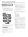
»
DA-302
Dual Digital Audio Tape Deck
OWNER’S MANUAL
D00313200A
Important Safety Precautions
Ü
ÿ
Ÿ
CAUTION: TO REDUCE THE RISK OF ELECTRIC SHOCK, DO NOT REMOVE COVER
(OR BACK). NO USER-SERVICEABLE PARTS INSIDE. REFER SERVICING TO QUALIFIED SERVICE PERSONNEL.
The lightning flash with arrowhead symbol, within equilateral triangle, is intended to alert
the user to the presence of uninsulated “dangerous voltage” within the product’s enclosure
that may be of sufficient magnitude to constitute a risk of electric shock to persons.
The exclamation point within an equilateral triangle is intended to alert the user to the presence of important operating and maintenance (servicing) instructions in the literature
accompanying the appliance.
This appliance has a serial number located on the
rear panel. Please record the model number and
serial number and retain them for your records.
Model number
Serial number
WARNING: TO PREVENT FIRE OR SHOCK
HAZARD, DO NOT EXPOSE THIS
APPLIANCE TO RAIN OR MOISTURE.
Important (for U.K. Customers)
For U.S.A
TO THE USER
DO NOT cut off the mains plug from this equipment. If the plug fitted is not suitable for the power
points in your home or the cable is too short to
reach a power point, then obtain an appropriate
safety approved extension lead or consult your
dealer.
If nonetheless the mains plug is cut off, remove the
fuse and dispose of the plug immediately, to avoid
a possible shock hazard by inadvertent connection
to the mains supply.
If this product is not provided with a mains plug, or
one has to be fitted, then follow the instructions
given below:
IMPORTANT: The wires in this mains lead are coloured in
accordance with the following code:
GREEN-AND-YELLOW : EARTH
BLUE
: NEUTRAL
BROWN
: LIVE
This equipment has been tested and found to comply with the limits for a Class A digital device, pursuant to Part 15 of the FCC Rules. These limits are
designed to provide reasonable protection against
harmful interference when the equipment is operated in a commercial environment. This equipment
generates, uses, and can radiate radio frequency
energy and, if not installed and used in accordance
with the instruction manual, may cause harmful
interference to radio communications.
Operation of this equipment in a residental area is
likely to cause harmful interference in which case
the user will be required to correct the interference
at his own expense.
CAUTION
Changes or modifications to this equipment not
expressly approved by TEAC CORPORATION for
compliance could void the user's authority to operate this equipment.
WARNING: This apparatus must be earthed.
As the colours of the wires in the mains lead of this apparatus may not correspond with the coloured markings
identifying the terminals in your plug proceed as follows:
The wire which is coloured GREEN-and-YELLOW must
be connected to the terminal in the plug which is marked
by the letter E or by the safety earth symbol ç or
coloured GREEN or GREEN-and-YELLOW.
The wire which is coloured BLUE must be connected to
the terminal which is marked with the letter N or coloured
BLACK.
The wire which is coloured BROWN must be connected
to the terminal which is marked with the letter L or
coloured RED.
When replacing the fuse only a correctly rated approved
type should be used and be sure to re-fit the fuse cover.
IF IN DOUBT — CONSULT A COMPETENT
ELECTRICIAN.
2
For the consumers in Europe
WARNING
This is a Class A product. In a domestic environment, this
product may cause radio interference in which case the
user may be required to take adequate measures.
Pour les utilisateurs en Europe
AVERTISSEMENT
Il s'agit d'un produit de Classe A. Dans un environnement
domestique, cet appareil peut provoquer des interférences
radio, dans ce cas l'utilisateur peut être amené à prendre
des mesures appropriées.
Für Kunden in Europa
Warnung
Dies ist eine Einrichtung, welche die Funk-Entstörung nach
Klasse A besitzt. Diese Einrichtung kann im Wohnbereich
Funkstörungen versursachen ; in diesem Fall kann vom
Betrieber verlang werden, angemessene Maßnahmen
durchzuführen und dafür aufzukommen.
Safety Instructions
CAUTION:
≠ Read all of these Instructions.
≠ Save these Instructions for later use.
≠ Follow all Warnings and Instructions marked on the audio
equipment.
1) Read instructions — All the safety and operating instructions
should be read before the product is operated.
2) Retain instructions — The safety and operating instructions
should be retained for future reference.
3) Heed Warnings — All warnings on the product and in the operating instructions should be adhered to.
4) Follow instructions — All operating and use instructions should
be followed.
5) Cleaning — Unplug this product from the wall outlet before cleaning. Do not use liquid cleaners or aerosol cleaners. Use a damp cloth for
cleaning.
6) Attachments — Do not use attachments not recommended by the
product manufacturer as they may cause hazards.
7) Water and Moisture — Do not use this product near water _ for
example, near a bath tub, wash bowl, kitchen sink, or laundry tub; in a
wet basement; or near a swimming pool; and the like.
8) Accessories — Do not place this product on an unstable cart,
stand, tripod, bracket, or table. The product may fall, causing serious
injury to a child or adult, and serious damage to the product. Use only
with a cart, stand, tripod, bracket, or table recommended by the manufacturer, or sold with the product. Any mounting of the product should
follow the manufacturer’s instructions, and should use a mounting accessory recommended by the manufacturer.
9) A product and cart combination should be moved with care. Quick
stops, excessive force, and uneven surfaces may cause the product and
cart combination to overturn.
10) Ventilation — Slots and openings in the cabinet are provided for
ventilation and to ensure reliable operation of the product and to protect
it from overheating, and these openings must not be blocked or covered.
The openings should never be blocked by placing the product on a bed,
sofa, rug, or other similar surface. This product should not be placed in a
built-in installation such as a bookcase or rack unless proper ventilation
is provided or the manufacturer’s instructions have been adhered to.
11) Power Sources — This product should be operated only from the
type of power source indicated on the marking label. If you are not sure
of the type of power supply to your home, consult your product dealer or
local power company. For products intended to operate from battery
power, or other sources, refer to the operating instructions.
12) Grounding or Polarization — This product may be equipped
with a polarized alternating-current line plug (a plug having one blade
wider than the other). This plug will fit into the power outlet only one
way. This is a safety feature. If you are unable to insert the plug fully into
the outlet, try reversing the plug. If the plug should still fail to fit, contact your electrician to replace your obsolete outlet. Do not defeat the
safety purpose of the polarized plug.
13) Power-Cord Protection — Power-supply cords should be routed
so that they are not likely to be walked on or pinched by items placed
upon or against them, paying particular attention to cords at plugs, convenience receptacles, and the point where they exit from the product.
14) Outdoor Antenna Grounding — If an outside antenna or cable
system is connected to the product, be sure the antenna or cable system
is grounded so as to provide some protection against voltage surges and
built-up static charges. Article 810 of the National Electrical Code,
ANSI/NFPA 70, provides information with regard to proper grounding of
the mast and supporting structure, grounding of the lead-in wire to an
antenna discharge unit, size of grounding conductors, location of antenna-discharge unit, connection to grounding electrodes, and requirements
for the grounding electrode.
"Note to CATV system installer:
This reminder is provided to call the CATV system installer’s attention
to Section 820-40 of the NEC which provides guidelines for proper
grounding and, in particular, specifies that the cable ground shall be connected to the grounding system of the building, as close to the point of
cable entry as practical.
Example of Antenna Grounding as per
National Electrical Code, ANSI/NFPA 70
ANTENNA
LEAD IN
WIRE
GROUND
CLAMP
ANTENNA
DISCHARGE UNIT
(NEC SECTION 810-20)
ELECTRIC
SERVICE
EQUIPMENT
GROUNDING CONDUCTORS
(NEC SECTION 810-21)
GROUND CLAMPS
POWER SERVICE GROUNDING
ELECTRODE SYSTEM
(NEC ART 250. PART H)
NEC - NATIONAL ELECTRICAL CODE
15) Lightning — For added protection for this product during a lightning storm, or when it is left unattended and unused for long periods of
time, unplug it from the wall outlet and disconnect the antenna or cable
system. This will prevent damage to the product due to lightning and
power-line surges.
16) Power Lines — An outside antenna system should not be located
in the vicinity of overhead power lines or other electric light or power
circuits, or where it can fall into such power lines or circuits. When
installing an outside antenna system, extreme care should be taken to
keep from touching such power lines or circuits as contact with them
might be fatal.
17) Overloading — Do not overload wall outlets, extension cords, or
integral convenience receptacles as this can result in risk of fire or electric shock.
18) Object and Liquid Entry — Never push objects of any kind into
this product through openings as they may touch dangerous voltage
points or short-out parts that could result in a fire or electric shock. Never
spill liquid of any kind on the product.
19) Servicing — Do not attempt to service this product yourself as
opening or removing covers may expose you to dangerous voltage or
other hazards. Refer all servicing to qualified service personnel.
20) Damage Requiring Service — Unplug this product from the
wall outlet and refer servicing to qualified service personnel under the
following conditions:
a) when the power-supply cord or plug is damaged.
b) if liquid has been spilled, or objects have fallen into the product.
c) if the product has been exposed to rain or water.
d) if the product does not operate normally by following the operating
instructions. Adjust only those controls that are covered by the operating
instructions as an improper adjustment of other controls may result in
damage and will often require extensive work by a qualified technician
to restore the product to its normal operation.
e) if the product has been dropped or damaged in any way.
f ) when the product exhibits a distinct change in performance _ this
indicates a need for service.
21) Replacement Parts — When replacement parts are required, be
sure the service technician has used replacement parts specified by the
manufacturer or have the same characteristics as the original part.
Unauthorized substitutions may result in fire, electric shock, or other
hazards.
22) Safety Check — Upon completion of any service or repairs to this
product, ask the service technician to perform safety checks to determine
that the product is in proper operating condition.
23) Wall or Ceiling Mounting — The product should be mounted to
a wall or ceiling only as recommended by the manufacturer.
24) Heat — The product should be situated away from heat sources
such as radiators, heat registers, stoves, or other products (including
amplifiers) that produce heat.
3
Section 1 : Introduction
Thank you for purchasing the TASCAM DA-302. To meet
the requirements of professional applications, the DA-302
is provided with the following functions.
… A variety of dubbing modes (normal/high speed/program/append)
… Dual recording
… Continuous recording/playback (with more than one
deck) possible
… Tape duplication using more than one deck
… Subcode data recording/editing
Before using your new deck, read this manual over carefully to be sure that you understand how to operate it correctly and know how to take advantage of its many functions. After reading this manual, keep it on hand for
future reference.
Table of Contents
Important Safety Precautions .......................................... 2
Safety Instructions........................................................... 3
Section 1 : Introduction ................................................. 4
1-1.
1-2.
1-3.
1-4.
Configuration ...................................................... 5
Memory backup.................................................... 5
Installation and operation precautions ................. 5
Condensation ........................................................ 5
Section 2 : DAT cassettes.............................................. 6
2-1. Structure of a DAT cassette.................................. 6
2-2. Loading a DAT cassette ....................................... 6
Section 3 : Block diagram ............................................. 7
Section 4 : Features and controls ................................ 9
4-1. Front panel.......................................................... 10
4-2. Rear panel........................................................... 13
4-3. RC-D302 remote control unit ........................... 14
Section 5 : Recording .................................................. 15
5-1. Normal recording ............................................... 15
5-1-1. Recording analog input signals ................... 15
5-1-2. Recording digital input signals ................... 15
5-2. Dubbing .............................................................. 16
5-2-1. Making an identical tape including
subcodes....................................................... 16
5-2-2. Dubbing a tape from the middle.................. 16
5-2-3. Making a tape with the program order
changed ........................................................ 16
5-3. Dual recording.................................................... 17
5-4. Continuous recording ......................................... 17
Section 6 : Playback..................................................... 18
6-1.
6-2.
6-3.
6-4.
6-5.
6-6.
Normal playback ................................................ 18
Continuous playback .......................................... 18
Skip playback ..................................................... 18
Single playback .................................................. 18
Repeat playback ................................................. 19
Program playback............................................... 19
Section 7 : Recording/editing of subcode data......... 20
7-1. Subcode data....................................................... 20
7-2. Start ID ............................................................... 20
4
7-2-1. Recording the Start ID automatically.......... 20
7-2-2. Recording the Start ID manually................. 20
7-2-3. Erasing the Start ID ..................................... 21
7-3. Skip ID ............................................................... 21
7-3-1. Recording the Skip ID................................. 21
7-3-2. Erasing the Skip ID ..................................... 22
7-4. End ID ................................................................ 22
7-4-1. Recording the End ID.................................. 22
7-4-2. Erasing the End ID ...................................... 22
7-5. Program numbers ............................................... 22
7-5-1. Recording the program number................... 22
7-5-2. Erasing the program number ....................... 22
7-5-3. Renumber..................................................... 22
7-6. ABS time ............................................................ 23
7-7. Program time ...................................................... 23
Section 8 : Convenient functions ............................... 24
8-1. Rec muting ......................................................... 24
8-2. Skip search ......................................................... 24
8-3. Direct search....................................................... 24
8-4. Locating function ............................................... 24
8-4-1. Setting the memo point ............................... 24
8-4-2. Correcting the memo point.......................... 24
8-4-3. Locating a memo point................................ 24
8-5. Blank search ....................................................... 25
Section 9 : Using more than one DA-302................... 26
9-1. Continuous recording with more than
one DA-302 ........................................................ 26
9-2. Duplicating ......................................................... 27
9-3. Continuous playback with more than
one DA-302 ........................................................ 27
Section 10 : Menu ......................................................... 28
Section 11 : Specifications.......................................... 30
Section 12 : Warning Indications and
Error messages ....................................... 32
12-1. Warning Indecations during operation ............. 24
12-2. Error Messages................................................. 24
Section 13 : Optional Accessories ............................. 33
Section 1 : Introduction
1-1. Configuration
Rack mounting
Install this deck with the provided mount screw kit as
illustrated.
This deck consists of the following.
1.DA-302 main unit
2.Accessories
Mount screw kit
RC-D302 remote control unit
Owner's manual
1-2. Memory backup
AUTO ID mode, AUTO ID detection level, memo point
and menu setting data are all retained in the DA-302’s
internal memory even when the power is turned off.
1-3. Installation and operation precautions
… Do not operate this deck when the temperature is outside the operating range of 5˚C to 35˚C. To prevent
malfunctions, do not install this deck anywhere where
it could be exposed to dust or subject to high humidity.
… Do not apply excessive force. This could damage the
internal circuitry or the cabinet.
… Use a soft cloth (such as a silicone cloth) to clean the
cabinet. If the unit is very dirty, wipe the dirt off with
a cloth dipped in diluted detergent. Do not use solvents
such as thinner and benzine as these can melt plastic or
coated surfaces and fade characters inscribed on the
panel.
… Because of improvements in design and specifications,
the product shown in illustrations in this manual may
differ from the actual product.
Note:
When mounting this deck in a rack, do not reinstall the
mount screws after removing the deck’s feet or you may
damage PCBs or other internal components. Handle the
removed feet carefully.
1-4. Condensation
When you move the deck from a cold place to a warm
place or use it after a sudden temperature change, condensation may occur. If this happens, leave the power on, but
do not operate the deck. After one or two hours, turn the
power off and then on again.
For CANADA
AC POWER CORD CONNECTION
CORDON DE CONNEXION CA
CAUTION :
TO PREVENT ELECTRIC SHOCK MATCH WIDE
BLADE OF PLUG TO WIDE SLOT, FULLY INSERT.
ATTENTION :
POUR ÉVITER LES CHOCS ÉLECTRIQUES, INTRODUIRE LA LAME LA PLUS LARGE DE LA FICHE
DANS LA BORNE CORRESPONDANTE DE LA
PRISE ET POUSSER JUSQU' AU FOND.
5
Section 2 : DAT cassettes
2-1. Structure of a DAT cassette
120-minute cassettes or longer (180-min cassette, etc.)
When you use a thin tape (120 minutes or longer),
operation and performance may be affected. Thin
tapes can also get tangled inside the mechanism. For
best results, do not use thin tapes.
Top view
2-2. Loading a DAT cassette
1
2.
3.
4.
Bottom view
Press the POWER switch to turn the power on.
Press the EJECT key to open the cassette holder.
Load a cassette.
Push the cassette holder to close it.
… When ejecting the cassette, hold both ends of the cassette so as not to prevent the sliding cover from moving
back into place.
Identification Hole
2
3
ˆ
ˆ
ˆ
Metal coating or equivalent/ 13 µm
tape thickness
ˆ
ˆ
¨
ˆ
ˆ
Metal coating or equivalent/ Thin tape
¨
1.5 time track pitch/ 13 µm tape
thickness
ˆ
¨
_
¨
_
1.5 time track pitch/ Thin tape
¨
Where: " ¨ " = Open
‚
…
…
…
Signified
1
"
(Reserved for auxiliary tape type
definitions)
ˆ " = Closed
Hole #4 shows "prerecorded" (Open) or not (Closed).
Dimensions: 73 x 54 x 10.5 mm (W x D x H)
Tape width: 3.81 mm
The cassette shells are designed to prevent the tape
from being touched directly by hand.
Notes:
… DAT cassettes record and play in one direction only.
Do not load DAT cassettes upside down.
… Do not use force to open the tape protection lid and do
not pull the tape out and touch it with your fingers.
… Store the DAT cassettes in their plastic cases.
… Do not place DAT cassettes on a television, speaker or
near equipment which could generate a magnetic field.
6
4-1. Front panel
1 POWER switch
2 SKIP keys
For skip search. (úp.24)
3 STANDBY key
With this key ON (LED lit), the Play-Pause mode is
automatically engaged after skip search, direct search,
or location search.
4 EJECT key
Press to load or unload the cassette.
5 COUNTER MODE key
To switch the time mode on the time display. Each time
this key is pressed, the mode changes in the following
order.
ABS time ∑ PGM time ∑ REMAIN time ∑
Tape counter
… ABS (absolute) time:
Shows the elapsed (absolute) time from the beginning of the tape up to the current position in hours,
minutes and seconds.
·In the Long Play mode, the displayed time differs
from the actual time. Double the displayed time to
get the actual time.
… PGM (program) time:
Shows the elapsed time from the beginning of each
program (start ID) in hours, minutes and seconds.
… REMAIN time:
Shows the tape remaining time.
·If a "TOC (Table Of Contents)" is written on the
tape (such as a commercially-available music
tape), the remaining time is shown in hours, minutes and seconds. If there is no "TOC", the time is
shown in hours and minutes.
·When "- -- --" is displayed, it means that the
remaining time is being calculated. Once the calculation is complete, the time is shown.
·In the Long Play mode, the displayed time differs
from the actual time. Double the displayed time to
get the actual time.
… Tape counter:
Counts according to the tape running.
·When the "Dig Out" menu is set to "AES/EBU"
(úp.28), time code is shown if it is written on the
tape.
10
6 RESET/MEMO (ABS) key
… When pressed with the counter mode set to Tape
Counter, the counter value is reset to "00 00".
… When pressed with the counter mode set to ABS, the
current tape position point is stored in memory for
later direct access.
7 Display
Displays different information regarding the unit’s status. The information displayed varies according to the
mode.
1 1, 2
Shows the deck selected by the SELECT 1/2 key.
2 Time display
Time selected by the COUNTER MODE key is
shown. Also, menu contents are shown.
3 PNO
Lights when the program number is shown in the
program number/margin display.
4 Program number/margin display
… When performing recording/rec-pause/sampling
monitor, or when the MARGIN RESET key is
pressed during playback, a margin value is shown.
The margin to the full scale level is shown in the
range 0 dB to 39 dB. Until the MARGIN RESET
key is pressed, the margin value for the input signal at maximum is maintained. If the margin
value exceeds the full scale level, 0 blinks.
… In cases than those above, the program number is
shown.
5 MARG
Lights when the margin value is shown in the program number/margin display.
6 SLAVE
If more than one DA-302 is connected, and this
deck is set to SLAVE, this indicator lights.
7 DIGITAL IN
Lights when "DIGITAL" is selected with the
INPUT switch.
8 Dubbing mode display
DUB MODE HIGH:
Lights in the High-Speed Dubbing mode.
DUB MODE NORM:
Lights in the Normal-Speed Dubbing mode.
DUB MODE PGM:
Lights in the Program Dubbing mode.
DUB MODE APPEND:
Lights in the Append Dubbing mode.
9 AUDIO ID
Lights when the Start ID Auto Writing mode is
selected.
Section 4 : Features and Controls
0 ID-related display
Shows the indication for the deck selected by the
SELECT 1/2 key.
START WRT:
Lights when the Start ID Manual Writing mode is
selected.
START ERASE:
Lights when Start ID erasing is selected.
SKIP WRT:
8 COMMON MODE switch
1 & 2:
Select to engage both Deck 1 and Deck 2 in the
Record or Play mode at the same time.
1 ∑ 2:
Continuous playback or recording on Deck 1 and
Deck 2.
OFF:
For independent operation of Deck 1 and Deck 2.
Lights when Skip ID writing is selected.
SKIP ERASE:
Lights when Skip ID erasing is selected.
END WRT:
Lights when End ID writing is selected.
RENUM:
Lights when renumbering is selected.
START:
Lights when the Start ID is detected.
9 Fs switch
… When recording analog input signals, select the
sampling frequency (32k, 44.1k, 48k).
·When 32k is selected, the Long Play mode is
engaged.
·When recording digital input signals, the sampling frequency is automatically determined
according to the input signals.
SKIP:
Lights when the Skip ID is detected.
END:
Lights when the End ID is detected.
q Sampling frequency display
… When an analog signal is being recorded, the sampling frequency (48.0k, 44.1k, 32.0k) selected by
the Fs switch is lit.
… When a digital signal is being recorded, the sampling frequency (48.0k, 44.1k, 32.0k) of the input
signal is lit.
·When "DIGITAL" is selected with the INPUT
switch and recording is performed without digital signal input, 48.0k blinks.
… LP lights in the Long Play mode.
w Peak level meter
… Shows the input signal level during
recording/record-pause/sampling monitor.
… The playback signal level is shown during playback.
… When the input or playback signal level surpasses
the full-scale level, the OVER section lights.
e Time-related display
ABS:
Lights when the ABS time is shown on the time
display.
PGM:
Lights when the PGM time is shown on the time
display.
REMAIN:
Lights when the REMAIN time is shown on the
time display.
r Repeat display
Shows the indication for the deck selected by the
SELECT 1/2 key.
REPEAT:
Lights in the One-Program Repeat mode.
ALL REPEAT:
0 MARGIN RESET key
… Resets the margin value when pressed while the
margin value is shown in the program number/margin display.
·When holding this key pressed, the margin value
corresponding to each input signal is shown continuously.
… Shows the margin value for as long as it is pressed,
when pressed while the program number is shown
in the program number/margin display during playback.
q INPUT level controls
Use to adjust the recording level.
w SELECT 1/2 key
To select the control deck for Deck 1 and Deck 2 (ID
MODE key, EXECUTE key).
When setting the menu, use to select the deck as
required.
e ANALOG INPUT switch
Set this switch when input signals are analog.
UNCAL:
To adjust the recording level with the INPUT level
controls.
CAL:
The input and output levels are fixed and the recording level cannot be adjusted.
·For the specified input level, the level meter shows
-16 dB.
r INPUT switch
Set this switch according to input signals.
ANALOG:
Select when input signals are analog.
DIGITAL:
Select when input signals are digital.
Lights in the All-Program Repeat mode.
11
Section 4 : Features and Controls
t PHONES OUT switch
1 (2):
Outputs Deck 1 (Deck 2) playback signals from the
PHONES jack.
·Outputs input signals when performing recording/record-pause/sampling monitor.
MIX:
Outputs mixed playback signals from both Deck 1
and Deck 2.
y PHONES control
Adjusts PHONES jack signal output level.
d RECORD key
… Press together with the PLAY key to start recording.
(LED lights.)
… Engages the Sampling Monitor mode when pressed
in the Stop mode. (LED lights.)
To release the Sampling Monitor mode, press the
STOP key.
·Sampling Monitor mode:
As in the Record-Pause mode, the Sampling
Monitor mode allows you to monitor input signals.
The difference is that the head drum does not rotate
in the Sampling Monitor mode and there is no contact between head and tape.
u PHONES jack
Connect stereo headphones.
f REC MUTE key
Use to mute recording. (úp.24)
i REW key
To rewind the tape.
·When pressed during playback, 2 times or 4 times
normal speed reverse cueing takes place. (úp.18)
o F FWD key
To fast forward the tape.
·When pressed during playback, 3 times or 6 times
normal speed forward cueing takes place. (úp.18)
p STOP key
To stop the tape running.
g Menu-related key
Use to show the menu or to change the menu settings.
(úp.28)
h EXECUTE key
Press to write/erase ID of each type.
j DUBBING key
Press to execute dubbing.
When the dubbing mode is selected with the DUB
MODE key, the LED blinks. Pressing this key in this
status starts dubbing operation and the LED lights.
a PLAY key
To play back the tape. (LED lights.)
k ID MODE key
Use for writing/erasing ID of each type. (úp.20)
s PAUSE key
Temporarily stops the tape during recording or playback. (LED lights.) To resume recording or playback,
press the PLAY key.
·Engages the Play-Pause mode when pressed in the
Stop mode.
·Engages the Record-Pause mode when pressed
together with the RECORD key.
·To protect the heads, the Play-Pause mode is automatically released after about 8 minutes and the
Stop mode is engaged.
·To protect the heads, the Record-Pause mode is
automatically released after about 8 minutes and the
Sampling Monitor mode is engaged.
12
l DUB MODE key
Use to select the Dubbing mode. The selected mode is
shown in the display. (úp.16)
; AUTO ID key
Use to automatically write the Start ID. (úp.20)
Section 4 : Features and Controls
4-2. Rear panel
z ANALOG (UNBALANCED) connectors
IN (L, R):
Analog input connectors for Deck 1.
·During dual recording or continuous recording,
these connectors are used as the input connectors
common for Deck 1 and Deck 2.
OUT 1 (L, R):
Analog output connectors for Deck 1.
OUT 2 (L, R):
Analog output connectors for Deck 2.
CASCADE OUT (L, R):
When more than one DA-302 is used, output analog
signals from these connectors. (úp.26)
·To select signals for output, refer to "Cas Out" on
the menu. (úp.28)
x DIGITAL connectors
INPUTS (1, 2):
Digital input connectors for Deck 1 and Deck 2.
OUTPUTS (1, 2):
Digital output connectors for Deck 1 and Deck 2.
CASCADE OUT:
When using more than one DA-302, output digital
signals from this connector.
·To select signals for output, refer to "Cas Out" on
the menu. (úp.28)
c EXT CONTROL connectors
Use when connecting more than one DA-302 using the
optional WR-7000 connection cable. (úp.26)
v REMOTE IN connector
Connect the provided RC-D302 remote control unit.
13
Section 4 : Features and Controls
4-3. RC-D302 remote control unit
1 START key
Use to perform direct search play. (úp.24)
2 Numeric keypad
Use to directly select the program. (úp.24) Also, use
to enter the numerical values for memo point.
3 MENU (<) key
Functions in the same way as when the > key is
pressed while pressing the SHIFT key on the main unit.
4 CLEAR key
When directly selecting the program, use this key to
cancel the selected program number or to clear the
numeric value for the memo point.
5 MENU ( – ) key
Functions in the same way as when the MENU key is
pressed while pressing the SHIFT key on the main unit.
6 LOCATE key
Locate the tape position at the memo point. (úp.24)
7 SAMPLING MONITOR key
Press to engage the Sampling Monitor mode. The same
function as when only the RECORD key on the main
unit is pressed.
8 RECORD key
The function of this key is different from that of the
RECORD key on the main unit. Pressing this key
engages the Record-Pause mode.
·Other keys function in the same way as the corresponding keys on the main unit.
14
Section 5 : Recording
Note:
Before recording, select Copy ID from the menu.
(úp.28)
The Copy ID cannot be changed after recording.
5-1. Normal recording
Normal recording means recording on Deck 1 or Deck 2
alone.
However, analog input signals can be recorded only on
Deck 1. Recording analog input signals on Deck 2 is not
possible.
… When recording on a new blank tape, record a lead-in
mark before starting recording.
5-1-1. Recording analog input signals
1
Set the COMMON MODE switch to OFF.
2
Connect the source to the ANALOG IN connectors.
3
Set the INPUT switch to ANALOG.
4
Select the sampling frequency (32k, 44.1k, 48k) with
the Fs switch.
·When 32k is selected, the Long Play mode is
engaged.
5
Press the RECORD key to engage the Sampling
Monitor mode.
·When using the remote control unit, press the SAMPLING MONITOR key.
6
Adjust the input signal level with the INPUT level
control.
·When the ANALOG INPUT switch is set to CAL,
the input and output level is fixed. It is preset at the
factory so that the level meter shows -16 dB for the
specified input level of -10 dBV. To adjust the
recording level, set this switch to UNCAL.
7
Pressing the PLAY key while pressing the RECORD
key starts recording.
5-1-2. Recording digital input signals
1
Set the COMMON MODE switch to OFF.
2
Connect the source to the DIGITAL IN connector for
the Deck 1 (Deck 2).
3
Set the INPUT switch to DIGITAL.
4
Pressing the PLAY key while pressing the RECORD
key of Deck 1 (Deck 2) starts recording.
·When performing digital-to-digital copy from a
DAT deck or a CD player, set the detection level to
"dd" in the AUTO ID mode to record the Start ID
and Skip ID (DAT only) at the same time. (úp.20)
Recording lead-in mark
When recording on a non-recorded tape, it is necessary to record a lead-in mark. The lead-in mark is
an area where no signal is recorded and should be
recorded at the start of the tape so that the start of a
program is not clipped during recording or playback.
(1) Rewind the tape to the beginning of the tape with
the REW key.
(2) Press the PAUSE key while pressing the
RECORD key. The lead-in mark is automatically
recorded, then the Record-Pause mode is
engaged.
… With non-recorded tapes, this operation is performed automatically even if recording is started
without performing operation (2). When recording
a source from which audio signals are input immediately after recording starts, be sure to perform
the above operations before starting recording.
… When you rewind a tape on which a lead-in mark
has been recorded, the lead-in mark is played
back automatically, then the tape stops. While the
lead-in mark is played back, "BB" is shown in the
program number display.
15
Section 5 : Recording
5-2. Dubbing
Dubbing means copying audio signals from Deck 1 to
Deck 2.
… The playback sound during dubbing is output from the
ANALOG OUT and DIGITAL OUT connectors for
Deck 1 and Deck 2.
·For high-speed dubbing, signals are not output to the
DIGITAL OUT connectors.
When high-speed dubbing is performed for a tape
recorded in the Long Play mode, no signal is output
to the ANALOG OUT connector as well.
5-2-1. Making an identical tape including subcodes
1
Load the source tape in Deck 1 and the recording tape
in Deck 2.
2
Set the COMMON MODE switch to OFF.
3
Select the Dubbing mode with the DUB MODE key.
·For dubbing at high speed (2 times normal speed),
select DUB MODE HIGH and for dubbing at normal speed, select DUB MODE NORM.
·A tape recorded in the Long Play mode can be
dubbed at high speed (4 times normal speed).
4
When the DUBBING key is pressed, the tapes in Deck
1 and Deck 2 are rewound, then dubbing starts.
… To stop dubbing in the middle, press the STOP key on
Deck 1 or Deck 2.
5-2-2. Dubbing a tape from the middle
1
Set the COMMON MODE switch to OFF.
2
Select the DUB MODE APPEND with the DUB
MODE key.
3
Press the DUBBING key to start dubbing from that
point.
16
5-2-3. Making a tape with the program order
changed
1
Set the COMMON MODE switch to OFF.
2
Select Deck 1 with the SELECT 1/2 key.
3
Follow the procedure in "6.6 Program playback" to
select the programs to be dubbed.
4
Set the Dubbing mode to DUB MODE PGM with the
DUB MODE key.
5
Pressing the DUBBING key rewinds the tape in Deck
2 to the beginning of the tape, then starts dubbing
according to the program.
… To stop dubbing in the middle, press the STOP key on
Deck 1 or Deck 2.
… When the AUTO ID mode is engaged, a Start ID is
automatically recorded at the start of each program to
be recorded.
Section 5 : Recording
5-3. Dual recording
5-4. Continuous recording
Dual recording means recording the same input source on
both Deck 1 and Deck 2.
Continuous recording means recording one input source
continuously using tapes in Deck 1 and Deck 2.
1
Connect the input source to the ANALOG IN connectors if it is analog and to the DIGITAL IN "1" connector if it is digital.
·Connecting it to the DIGITAL "2" connector is
invalid.
1
Connect the input source to the ANALOG IN connectors for analog input signals and to the DIGITAL IN
"1" connector for digital signals.
·The DIGITAL IN "2" connector is disabled.
2
Set the COMMON MODE switch to "1&2".
2
Set the COMMON MODE switch to "1 > 2".
3
For analog input signals, follow procedures 3 to 6 in
"5-1-1. Recording analog input signals". For digital
input signals, set the INPUT switch to DIGITAL.
3
For analog input signals, follow procedures 3 to 6 in
"5-1-1. Recording analog input signals". For digital
input signals, set the INPUT switch to DIGITAL.
4
Set "Seqtime" in the menu. (úp.28)
5
Set Deck 1 in the Record mode and start recording.
When the ABS time of Deck 1 reaches the time set
with "Seqtime", Deck 2 automatically starts recording.
6
Deck 1 rewinds the tape automatically to the beginning
either 3 minutes after the time set with ''Seqtime'' or
when the tape end is reached.
7
Deck 2 rewinds the tape automatically to the beginning
either 3 minutes after the time set with ''Seqtime'' or
when the tape end is reached.
4
When Deck 1 is set in the Record mode, recording
starts on both Deck 1 and Deck 2 simultaneously.
5
When the Stop key on Deck 1 is pressed, recording on
both Deck 1 and Deck 2 stops simultaneously.
… When the COMMON MODE switch is set to "1&2", the
STOP key, PLAY key, PAUSE key, RECORD key, F
FWD key, REW key and REC MUTE key on Deck 1
(Deck 2) are effective for both decks.
… The input signals during recording are output from the
ANALOG OUT connectors and the DIGITAL OUT
connector of Deck 1 and Deck 2.
… To stop recording in the middle, press the STOP key on
the deck which is recording.
… The input signals being recorded are output from the
ANALOG OUT connectors and DIGITAL OUT connector of Deck 1 (Deck 2).
17
Section 6 : Playback
6-1. Normal playback
1
Set the COMMON MODE switch to OFF.
2
Press the PLAY key to start playback.
… When the REW key (F FWD key) is pressed during
playback, 2 times (3 times) normal speed rewind cueing
(fast-forward cueing) is performed. Pressing it once
more allows 4 times (6 times) normal speed cueing.
Pressing it once more restores 2 times (3 times) cueing.
To restore normal playback, press the PLAY key.
… Holding the REW key (F FWD key) pressed for 1 second or more during playback performs 2 times (3 times)
normal speed rewind (fast forward) cueing for as long as
the key is pressed. Releasing it restores normal playback.
… Pressing the REW key during fast-forward cueing
switches to 2 times normal speed rewind cueing.
… Pressing the F FWD key during rewind cueing switches
to 3 times normal speed fast-forward cueing .
… Playback signals are output from the ANALOG OUT
and DIGITAL OUT connectors of Deck 1 (Deck 2).
6-2. Continuous playback
With continuous playback, the tapes in Deck 1 and Deck
2 are played back continuously.
1
Set "Seqtime" in the menu. (úp.28)
3
Press the PLAY key on Deck 1 to start playback.
When the ABS time of Deck 1 reaches the time set
with "Seqtime", Deck 2 starts playback automatically.
5
Deck 1 automatically rewinds the tape to the beginning
either 3 minutes after the time set with "Seqtime" or
when the tape end is reached.
Deck 2 automatically rewinds the tape to the beginning
either 3 minutes after the time set with "Seqtime" or
when the tape end is reached.
… The playback signals are output from the ANALOG
OUT and DIGITAL OUT connectors of Deck 1
(Deck 2).
18
6-3. Skip playback
When a Skip ID is detected during playback, the tape is
fast-forwarded to the next Start ID and resumes playback.
1
Select the deck with the SELECT 1/2 key.
2
Press the MENU key to show the following menu in
the time display.
Skip1
3
Off
Set to "On" with the UP/DOWN key to engage the
Skip Play mode.
… If the STANDBY key is set to ON, the Play-Pause mode
is engaged at the Start ID.
6-4. Single playback
Set the COMMON MODE switch to "1 > 2".
2
4
… The playback sound can also be monitored through the
ANALOG CASCADE OUTPUT connectors. When
"Cas Out" is set to "Auto" in the menu (úp.28), playback sound output is switched from Deck 1 to Deck 2 at
the time Deck 2 starts playback. In this status, if the
PLAY key of Deck 1 is pressed, you can monitor the
playback sound of Deck 1 again.
When a Start ID is detected during playback, this function
automatically engages the Play-Pause mode.
1
Select the deck with the SELECT 1/2 key.
2
Press the MENU key to show the following message in
the time display.
Single1
3
Off
Set to On" with the UP/DOWN key to engage the
Single Play mode.
Section 6 : Playback
6
Up to 50 programs can be programmed in the same
way.
This function allows one or all programs to be played back
repeatedly.
·With one program repeat, the tape is automatically
rewound to the previous Start ID when a Start ID is
detected.
·For all program repeat, the tape is automatically
rewound to the beginning when the tape end is reached
or the End ID is detected.
7
Press the EXECUTE key to start Program Playback.
1
Select the deck with the SELECT 1/2 key.
2
Press the MENU key to show the following menu in
the time display.
… Checking the programmed sequence
Each time the > key is pressed while the program
menu (e.g.: [PGM1
s01_03]) is displayed, the
step number changes, allowing you to check the program number.
(By pressing the > key while pressing the SHIFT key,
you can check the previous step number.)
… Adding to or changing the programmed sequence
To add a program number, display the step number with
"EE" and enter the program number. Adding a program
number in the middle of the program sequence is not
possible.
To change the program number, display the program
number to be changed by pressing the > key and enter
a new program number with the UP/DOWN key.
·To enter "EE", press the UP key and DOWN key
simultaneously or the CLEAR key on the remote
control unit.
6-5. Repeat playback
Repeat1
3
Off
Set to "Single" with the UP/DOWN key to engage the
One Program Repeat mode. Set to "All" to engage the
All Program Repeat mode.
… If the STANDBY key is set to ON in the One Program
Repeat mode, the Play-Pause mode is engaged at the
beginning of the program after one program has been
played.
… The last step is the step before the step in which "EE" is
shown in the program number input section on the
menu.
e.g.) In case of [PGM1
is the last step.
s03_EE], step 02 (s02)
6-6. Program playback
This function allows you to play back programs in a userspecified sequence.
1
Select the deck with the SELECT 1/2 key.
2
Press the MENU key to show the following menu in
the time display.
PGM1
3
Enter the program number of the program you want to
play first with the UP/DOWN key.
PGM1
4
s01_03
To program the program you want to play back second,
first press the > key and set the step number to "s02".
PGM1
5
s01_EE
s02_EE
Enter the program number of the program you want to
play back second with the UP/DOWN key.
PGM1
s02_05
19
Section 7 : Recording/editing of subcode data
7-1. Subcode data
Recordable subcode data is shown below.
… Start ID (recording time: 9 seconds*)
… Skip ID (recording time: 1 second*)
… End ID (recording time: 9 seconds*)
… Program number (recording time: 9 seconds*)
… ABS time
… Program time (recording time: 9 seconds*)
… The detection level can be adjusted to suit the recording
source.
(1) While holding the SHIFT key pressed, press the
AUTO ID key as many times as necessary to select
the desired level (-36 dB, -42 dB, -48 dB, -54 dB,
dd*).
(2) Release the SHIFT key to determine the level.
* When "dd" is selected, the ID is recorded by using
information from the digital signal interface
(SPDIF) input from the digital input connector.
“ When a DAT deck is connected to the digital
input connector, Start IDs and Skip IDs are
recorded corresponding to the Start IDs and Skip
IDs recorded on the DAT.
“ When a CD player is connected to the digital
input connector, Start IDs are recorded corresponding to the track numbers on the CD.
“ When a unit other than a DAT deck or a CD
player is connected to the digital input connector
or analog input connectors, the "-54 dB" setting
is used.
* Standard mode. Long Play recording time is twice that
in the Standard mode.
7-2. Start ID
A Start ID is code recorded at the beginning of each newly
recorded program and is used to locate the beginning of
that program during search. Start IDs can be recorded
automatically or manually.
Note:
Be sure to leave at least 9 seconds between Start IDs. If
the time between Start IDs is less than 9 seconds, a malfunction may occur during search. It is recommended to
leave 30 seconds or more to ensure proper operation.
7-2-2. Recording the Start ID manually
… Manual recording on the fly
1
Select the deck with the SELECT 1/2 key.
2
Press the ID MODE key so the "START WRT" lights
in the display.
3
During recording or playback, press the EXECUTE
key at the desired position to record the Start ID.
The "START WRT" blinks and the Start ID is recorded for 9 seconds from that point.
·When the COMMON MODE switch is set to
"1&2", the Start ID is recorded on tapes in both
Deck 1 and Deck 2 regardless of the setting of the
SELECT 1/2 key.
7-2-1. Recording the Start ID automatically
Press the AUTO ID key; "AUTO ID" lights in the display
and the Auto Recording mode is engaged.
·When the AUTO ID key is pressed, the detection level
is shown for about 1 second in the time display (initial
setting is -48 dB).
… To release the Auto Recording mode, press the AUTO
ID key again.
… Start IDs are recorded in the Auto Recording mode
under the following conditions.
* A signal exceeding the detection level is input after
recording starts
* A signal below the detection level continues for 3 or
more seconds during recording and is then followed by
a signal exceeding the detection level.
… Manual recording with menu
1
Select the deck with the SELECT 1/2.
2
Press the ID MODE key so that the "START WRT"
lights in the display.
3
Press the MENU key to show the following menu in
the time display.
Posi1
4
Press the RESET key during playback to capture the
ABS time at that time. The time is shown in hours,
minutes, seconds and frames in the time display. The
deck enters the Play-Pause mode.
Posi1
20
–¡––™––£––
0¡13™45£14
Section 7 : Recording/editing of subcode data
5
When the PLAY key is pressed, playback takes place
for about 3 seconds from the captured ABS time.
Then, the Play-Pause mode is engaged.
·In this status, press the UP and DOWN keys simultaneously or press the CLEAR key on the remote
control unit to restore the condition in step 3.
6
Each time the UP key or DOWN key is pressed in the
Play-Pause mode, the captured ABS time can be
changed by +5 frames or -5 frames (up to ±2 seconds).
Posi1
Posi1
Posi1
0¡13™45£09
fi DOWN key
0¡13™45£14
ı UP key
0¡13™45£19
3
During recording or playback, press the EXECUTE
key at the point where you want to record the Skip ID.
The "SKIP WRT" blinks and the Skip ID is recorded
for one second from that point.
·When the COMMON MODE switch is set to
"1&2", the Skip ID is recorded on tapes in both
Deck 1 and Deck 2 regardless of the setting of the
SELECT 1/2 key.
… Recording with the menu
1
Select the deck with the SELECT 1/2 key.
2
Press the ID MODE key so that the "SKIP WRT" lights
on the display.
3
Press the MENU key to show the following menu in
the time display.
Posi1
7
Repeat steps 5 and 6 to set the desired point, then
press the EXECUTE key. The Start ID is recorded
from that point.
4
7.2.3 Erasing the Start ID
1
Select the deck with the SELECT 1/2.
2
Press the ID MODE key so that "START ERASE"
lights in the display.
3
In the Stop or Play mode, press the EXECUTE key.
The tape is rewound to the previous Start ID and this
Start ID is erased while it is being played.
During erasing, the "START ERASE" blinks and
when erasing is complete, the normal playback is
restored.
Press the RESET key during playback to capture the
current ABS time. The time is shown in hours, minutes, seconds and frames in the time display. Then, the
deck enters the Play-Pause mode.
Posi1
0¡13™45£14
5
Press the PLAY key to play back the tape from the captured ABS time for about 3 seconds. Then the PlayPause mode is engaged.
·In this status, press the UP and DOWN keys simultaneously or press the CLEAR key on the remote
control unit to restore the condition in step 3.
6
Each time the UP or DOWN key is pressed in the PlayPause mode, the captured ABS time is changed by +5
or -5 frames (up to ±2 seconds).
Posi1
7-3. Skip ID
Posi1
Skip IDs are recorded to enable skip playback (úp.18).
7-3-1. Recording the Skip ID
–¡––™––£––
Posi1
0¡13™45£09
fi DOWN key
0¡13™45£14
ı UP key
0¡13™45£19
… Recording on the fly
1
Select the deck with the SELECT 1/2 key.
2
Press the ID MODE key so that the "SKIP WRT" lights
on the display.
21
Section 7 : Recording/editing of subcode data
7
Repeat steps 5 and 6 and when you determine the
desired point, press the EXECUTE key. From that
point, the Skip ID is recorded.
7-3-2 Erasing the Skip ID
1
Press the SELECT 1/2 key to select the deck.
2
Press the ID MODE key so that the "SKIP ERASE"
lights in the display.
3
During stop or playback, press the EXECUTE key.
The tape is rewound to the previous Skip ID and the
Skip ID is erased while it is played back.
During erasing, the "SKIP ERASE" blinks and when
the Skip ID has been erased, the normal playback is
restored.
7-4. End ID
The End ID marks the tape end position.
The point where the End ID is recorded is detected as the
tape end position and the tape cannot be advanced from
that point.
When the End ID is detected in the Fast Forward mode,
the tape is rewound to the beginning of the End ID and
stops for further recording.
When the End ID is detected during playback, the tape is
rewound to the beginning of the tape.
·When the End ID is detected, the "EE" lights in the program number display.
7-4-1. Recording the End ID
1
Press the SELECT 1/2 key to select the deck.
2
In the Record-Pause or Record mode, press the ID
MODE key so that the "END WRT" lights.
3
In the Record or Record-Pause mode, press the EXECUTE key at the point where you want to record the
End ID.
The "END WRT" blinks and the End ID is recorded for
9 seconds from that point. After recording, the tape is
rewound to the beginning of the End ID and stops.
·When the COMMON MODE switch is set to
"1&2", the End ID is recorded on tapes in both Deck
1 and Deck 2 regardless of the setting of the
SELECT 1/2 key.
7-4-2. Erasing the End ID
When the tape is fast-forwarded by pressing the F FWD
key, the tape stops at the beginning of the End ID.
Recording from that point erases the End ID.
22
7-5. Program numbers
The program number shows the number of the program
and is recorded with the Start ID at the beginning of each
program.
7-5-1. Recording the program number
Program numbers are automatically recorded at the same
time as Start IDs.
When recording is performed from the beginning of the
tape and Start IDs are automatically recorded, program
numbers are recorded in order from 01.
·When recording on a tape on which program numbers
have already been recorded, first play back the tape so
that the program number is shown in the display then
record the Start ID.
If the program number is not shown in the display and
the Start ID is recorded, the program number is not
recorded.
7-5-2. Erasing the program number
When the Start ID is erased, the program number is automatically erased.
7-5-3. Renumber
Renumber means renumbering from the first Start ID as
Program 01. Do this when the program numbers have not
been recorded correctly because a Start ID has been erased
or a new program has been inserted.
1
Press the SELECT 1/2 key to select the deck.
2
Press the ID MODE key so that the "RENUM" lights
in the display.
3
Press the EXECUTE key during stop or playback.
The tape automatically rewinds to the beginning.
When the first Start ID is detected, the program number is recorded.
After recording, the tape is advanced to the next Start
ID and the program number is recorded in the same
way.
Thus, the program numbers are recorded in order from
01. When the tape end or the End ID is detected, the
tape is rewound to the beginning and stops.
Section 7 : Recording/editing of subcode data
7-6. ABS time
The ABS time is the elapsed time (absolute time) from the
beginning of the tape.
When recording is performed from the beginning of the
tape, the ABS time is automatically recorded.
·When recording is performed from a point other than
the beginning of the tape, ABS time is not recorded.
·Even with a tape on which the ABS time has been
recorded, ABS time is not recorded if recording starts
from a non-recorded section.
·When recording continuously on a tape with the ABS
time recorded, fast forward the tape to the End ID or
execute Blank Search (úp.25) to wind the tape to the
point just before a non-recorded section, then start
recording. This ensures that the ABS time is recorded
continuously.
7-7. Program time
The program time means the elapsed time from the beginning of each program (Start ID).
The program time is recorded with the Start ID for 9 seconds in the same way as the program number.
When the Start ID is erased, the program time is erased at
the same time.
·The program time is recorded for 9 seconds. However,
when the part after that is played back, the program
time is shown using internal counting.
23
Section 8 : Convenient functions
8-1. Rec muting
When the REC MUTE key is pressed during recording, no
signals are recorded for about 4 seconds and the RecordPause mode is engaged.
·If the REC MUTE key has been held for 4 seconds or
more, releasing the key engages the Record-Pause
mode.
8-2. Skip search
8-4. Locating function
This allows you to set a memo point (one point) based on
the ABS time. You can access this point directly with the
Locate function.
8-4-1. Setting the memo point
1
Press the COUNTER MODE key to set the time mode
to ABS time.
2
Press the RESET/MEMO (ABS) key at the point
where you want to set the memo point. That point is
stored in memory.
·Setting is possible in any tape running mode.
This function lets you search for a Start ID.
1
When the  key is pressed once in the Stop/PlayPause/Play mode, the previous Start ID is searched. If
the ¯ key is pressed, the next Start ID is searched.
After the search is complete, tape playback starts.
… When a new memo point is set, the previous memo
point is erased.
8-4-2. Correcting the memo point
2
To search other Start IDs, simply press the  or
¯ key as many times as required.
·The number of times you have pressed the key is
shown in the program number display.
1
Press the SELECT 1/2 key to select the deck.
2
Press the MENU key to show the following menu in
the time display. The set memo point is shown.
… If the STANDBY key is set to ON, the Play-Pause mode
is engaged after search.
Memo1
3
8-3. Direct search
This function searches for a specific program number and
plays back the corresponding program. This function can
be used only with the remote control unit.
1
2
In the Stop/Play-Pause/Play mode, press the program
number with the numeric keypad. The specified program number blinks in the program number display.
·If you press the wrong program number, press the
CLEAR key to re-enter the program number.
Pressing the START key starts playback after search.
… If the STANDBY key is set to ON, the Play-Pause mode
is engaged after search.
24
0¡05™42£
Pressing the UP/DOWN key allows you to change the
memo point second by second.
·Press the UP and DOWN keys simultaneously or
the CLEAR key on the remote control unit to clear
the memo point.
After clearing the memo point, you can enter
numerical values with the numeric keypad on the
remote control unit.
8-4-3. Locating a memo point
Press the PLAY key while pressing the STOP key in the
Stop mode. The memo point is located and playback
starts.
·When using the remote control unit, press the LOCATE
key.
… If the STANDBY key is set to ON, the Play-Pause mode
is engaged after the memo point has been located.
Section 8 : Convenient functions
8-5. Blank search
To search a non-recorded section on a recorded tape, simply press the F FWD key. When the non-recorded section
is detected, the tape is rewound to the point just before the
non-recorded section and stops.
If the ABS time is recorded, the ABS time can be recorded continuously from this non-recorded section when
recording starts.
·When an END ID is recorded, the tape stops at the
beginning of the End ID.
·When a non-recorded section is detected, "- End -" is
shown in the time display.
25
Section 9 : Using more than one DA-302
9-1. Continuous recording with more than
one DA-302
6
Set Deck 1 in the master deck to the Record mode to
start recording.
When Deck 1 reaches the ABS time of Deck 1 set with
"Seqtime", Deck 2 starts recording.
When Deck 2 reaches the ABS time of Deck 2 of the
master deck, Deck 1 in the second deck receives the
command from the EXT CONTROL IN connector and
starts recording. This process continues from deck to
deck, enabling continuous recording.
7
To stop recording, press the STOP key on the deck
which is currently recording.
One input source can be recorded continuously on more
than one DA-302 beginning with the first deck, then the
second deck, and so on.
1
Connect DA-302s as shown in the figure.
·The connections marked with * in the figure shows
the connections for analog signal recording. When
recording digital signals, connect the recording
source to the master deck's DIGITAL INPUTS 1
connector and the DIGITAL CASCADE OUTPUT
connector to the slave deck's DIGITAL INPUTS 1
connector.
SOURCE
MASTER
∗
∗
SLAVE
WR-7000
∗
∗∗
SLAVE
Speakers
Amplifier
2
Set the first DA-302 to Master Deck and the other DA302s to Slave Deck. Set decks to master/slave deck
with "Control" in the menu. (úp.28)
3
For all connected DA-302s, perform procedures 2 to 4
in the "5.4 Continuous recording".
4
Press the REW key on Deck 1 in the master deck to
rewind the tapes in Deck 1 in the master deck and the
slave decks to the beginning.
·Only the REW key on Deck 1 of the master deck
controls the slave decks.
5
Press the REW key on Deck 2 in the master deck to
rewind the tape in Deck 2 in the master deck to the
beginning.
26
… After recording, each deck automatically rewinds the
tape to the beginning either 3 minutes after the time set
with "Seqtime" or when the tape end is reached.
Example:
First deck settings (master )
Seqtime: 2H00M00S
Second deck settings (slave)
Seqtime: 2H00M00S
Third deck settings (slave)
Seqtime: 2H00M00S
With these settings, the recording operation is as follows.
(1) When the ABS time of the first deck's Deck 1 reaches
2H00M00S, Deck 2 of the first deck starts recording.
(2) When the ABS time of the first deck's Deck 2 reaches
2H00M00S, Deck 1 of the second deck starts recording.
(3) When the ABS time of the second deck's Deck 1 reaches 2H00M00S, Deck 2 of the second deck starts
recording.
(4) When the ABS time of the second deck's Deck 2 reaches 2H00M00S, Deck 1 of the third deck starts recording.
(5) When the ABS time of the third deck's Deck 1 reaches
2H00M00S, Deck 2 of the third deck starts recording.
(6) When the ABS time of the third deck's Deck 2 reaches
2H03M00S or the tape is reached to its end, all operations are complete.
·If "Loop" in the menu of the master deck is set to
"On"(úp.28), Deck 1 of the first deck starts
recording when the ABS tme of the third deck’s
Deck 2 reaches 2H00M00S. In this case, change the
tape if required.
Section 9 : Using more than one DA-302
9-2. Duplicating
One source can be recorded on more than one deck at the
same time.
1
Connect DA-302s as shown in the figure in "9.1
Continuous recording with more than one DA-302".
·In this case, the connection marked with ** is not
necessary.
2
Set the first DA-302 to Master Deck and the other DA302s to Slave Deck. Set decks to master/slave deck
with "Control" in the menu. (úp.28)
3
For all connected DA-302s, perform procedures 2 to 3
in "5.3 Dual recording".
4
Press the REW key on Deck 1 of the master deck to
rewind the tapes in all decks to the beginning.
5
When the Record mode is engaged on Deck 1 on the
master deck, all decks automatically enter the Record
mode.
6
9-3. Continuous playback with more than
one DA-302
Continuous playback on more than one DA-302 is possible beginning with the first deck, then the second deck,
and so on.
1
Connect DA-302s as shown in the figure in "9.1
Continuous recording with more than one DA-302".
2
Set the first DA-302 to Master Deck and the other DA302s to Slave Deck. Set decks to master/slave deck
with "Control" in the menu. (úP.28)
3
For all connected DA-302s, perform procedures 1 to 2
in the "6.2 Continuous playback".
4
Press the REW key on Deck 1 in the master deck to
rewind the tapes in Deck 1 in the master deck and the
slave decks to the beginning.
·Only the REW key on Deck 1 of the master deck
controls the slave decks.
5
Press the REW key on Deck 2 in the master deck to
rewind the tape in Deck 2 in the master deck to the
beginning.
6
Press the PLAY key on Deck 1 of the master deck to
start playback.
When Deck 1 reaches the time set with "Seqtime",
Deck 2 starts playback.
When Deck 2 reaches the time set with ''Seqtime'',
Deck 1 in the second deck receives the command from
the EXT CONTROL IN connector and starts playback.
This process continues from deck to deck, enabling
continuous playback.
·This procedure is almost identical to that in "9.1
Continuous recording with more than one DA-302".
(The difference being that one is for playback and
the other is for recording.) For more details on
operation, refer to the example in "9.1 Continuous
recording with more than one DA-302".
7
To end the operation in the middle, press the STOP key
of the deck which is playing back.
To stop recording, press the STOP key on Deck 1 of
the master deck.
… If the COMMON MODE switch is set to "1&2", when
the STOP key, PLAY key, PAUSE key, RECORD key, F
FWD key, REW key or REC MUTE key on Deck 1 or
Deck 2 of the master deck is pressed, the command is
output to all slave decks.
… Each deck which starts playback rewinds the tape
automatically to the beginning either 3 minutes after
the time set with "Seqtime" or when the tape end is
reached.
27
Section 10 : Menu
You can change or display the settings for each mode in the Menu. The menu is shown in the time display.
The menu consists of two groups. Each group is accessed differently.
The tables below show the types of menus and the corresponding access methods.
·Press the MENU key to switch the menu item. Press the MENU key while pressing the SHIFT key to return to the previous menu item.
·Use the UP/DOWN key to change the settings in the menu.
·Press the COUNTER MODE key to return the menu screen to the normal time display.
·Menu settings are retained even when the power is turned off.
Menu (Group 1)
… In the normal time display mode, press the MENU key to access the following menus.
Menu
Set contents
Factory preset
Page to be referred for details
Skip 1 (2)
Off, On
Off
18
Single 1 (2)
Off, On
Off
18
Repeat 1 (2)
Off, Single, All
Off
19
Memo 1 (2)
ABS time
--
H
--
M
--
S
24
Posi 1 (2)
ABS time
--
H
--
M
--
S
20, 21
PGM 1 (2)
Step No. and program No.
S01_EE
19
E - - - - AH E- - - - AH
AH, AB, BH
AH
29
DrumT 1 (2)
xxxx H
29
·1 (2) in the menu shows the deck selected by the SELECT 1/2 key.
Menu (Group 2)
… In the normal time display mode, press the MENU key while pressing the > key to access the following menus.
Menu
Set contents
Factory preset
Page to be referred for details
Dig Out
SPDIF, AES/EBU
SPDIF
29
Control
Master, Slave
Master
29
Copy ID
Proh, 1gen, Free
Proh
29
Peak
Hold Off, Hold On
Hold On
29
Display
Normal, Bright, Dim
Normal
29
Seqtime
0H 15M 00S ~ 2H 30M 00S
2H 00M 00S
29
Cas Out
Auto, Input
Auto
29
Loop
Off, On
Off
29
28
Section 10 : Menu
Menu Details
… E - - - - AH E - - - - AH
Shows the error rate during playback.
·In the "----" section on the left, the error rate for Deck
1 is shown while in the "----" section on the right, that
for Deck 2 is shown.
·The section showing AH can be changed with the
UP/DOWN key.
… Peak Hold
Set the peak hold of the level meter to On or Off with
the UP/DOWN key.
·When set to On, the peak is held. However, the held
peak level is reset if the MARGIN RESET key is
pressed.
… Display
Select the brightness of the display with the UP/DOWN
key.
With AH display:
Shows the error rate of head A.
With AB display:
Shows the error rate of heads A and B.
With BH display:
Shows the error rate of head B.
·Display example:
When "E0030AH E0100AH" is shown, the error rate
of head A in the PCM area is 3 x 10⁻³ for Deck 1 and
1 x 10⁻² for Deck 2.
… Seqtime
Sets the start time for Deck 2 operation during continuous recording/playback with the UP/DOWN key. Can
be set in 1 minute increments (in 15 minute increments
with the > key) in the range of 0H15M00S to
2H30M00S.
When the ABS time of Deck 1 reaches the set time,
Deck 2 starts operation.
… DrumT 1 (2)
Shows the elapsed drum rotating time since the deck
was first used. Use this as a guide for regular maintenance.
When more than one DA-302 is connected for continuous recording/playback, and the ABS time of Deck 2
reaches the set time, the REC or PLAY command is output from the EXT CONTROL OUT connector.
… Dig Out
Select the digital output signal format, SPDIF (IEC958
TYPE II) or AES/EBU (IEC958 TYPE 1), using the
UP/DOWN key.
… Cas Out
Select the signals output from the CASCADE OUT connector with the UP/DOWN key.
… Control
When using more than one DA-302, set them to master/slave deck with the UP/DOWN key.
·When only one DA-302 is used, set to "Master".
When set to Input:
Signals input to the ANALOG IN connectors are output to the ANALOG CASCADE OUTPUT connector.
Also, signals input to the DIGITAL INPUTS connector for Deck1 are output from the DIGITAL CASCADE connector.
When set to Auto:
… Copy ID
Set the Copy ID with the UP/DOWN key. The Copy ID
shows how many generations of digital-to-digital copying (digital recording of digital signals) is possible.
The Copy ID is recorded when recording is carried out.
Proh: The copy prohibit ID (10) is recorded.
1gen: The ID (11) permitting copy up to the first gener-
ation is recorded.
Free: The ID (00) permitting copy is recorded.
·For digital-to-digital copying with an SCMS (Serial
Copy Management System) deck, see below.
When ID (10) is recorded:
A digital-to-digital copy is impossible.
When ID (11) is recorded:
One digital-to-digital copy is possible.
When ID (00) is recorded:
Multiple-generation digital-to-digital copying is
possible.
When either Deck 1 or Deck 2 plays back the tape, the
playback signal is output from the ANALOG CASCADE OUTPUT and DIGITAL CASCADE OUTPUT connectors.
When both Decks 1 and 2 are playing back tapes, the
sound from the deck which entered the Play mode
most recently is output. To output the sound from
another deck, press the PLAY key of another deck in
the Play mode.
In other cases, the output signals are the same as that
output when set to Input.
… Loop
Can be set only for the master deck.
When this is set to "On" with the UP/DOWN key, the
master deck starts operation again after the last slave
deck finishes the operation for continuous
recording/playback using more than one DA-302.
29
Section 11 : Specifications
Format :
Tape Speed :
Rotary head digital audio tape deck
8.15 mm/sec. (SP: Recording/playback)
12.225 mm/sec. (only for playback)
16.3 mm/sec. (SP: Double speed
dubbing, LP: 4 times normal speed
dubbing)
4.075 mm/sec. (LP: Recording/playback)
Recording Time :
120 minutes (SP: With a 120-minute
tape)
240 minutes (LP: With a 120-minute
tape)
Fast Winding/Rewinding Time :
Approx. 60 seconds (with a 120minute tape)
Channels :
Stereo 2 channels
Quantization :
16-bit linear (SP), 12-bit non-linear
(LP)
Error Correction Method : Doubled Reed Solomon code
Sampling Rates :
48 kHz (recording/playback)
44.1 kHz (recording/playback)
32 kHz (recording/playback)
Emphasis :
50 µsec./15 µsec (automatically
applied in the Play mode)
Frequency Response :
20 – 20 kHz ± 0.5 dB (48 kHz/44.1
kHz)
20 – 14.5 kHz ± 0.8 dB (32 kHz)
S/N :
More than 89 dB
Dynamic Range :
More than 89 dB
Total Harmonic Distortion :
Less than 0.007% (SP), less than
0.07% (LP)
(1 kHz for recording and playback,
full-scale)
Channel Separation :
More than 85 dB (1 kHz)
Wow and Flutter :
Unmeasurable (less than ±0.001%)
Analog Input/Output Connectors
IN :
RCA pin x 2
Normal Input Level :
–10 dBV (0.3 V), unbalanced
(FS – 16 dB)
Input Impedance :
20 kohms
OUT :
RCA pin x 4
Normal Output Level : –10 dBV (0.3 V), unbalanced
(FS – 16 dB)
Maximum Output Level : +6 dBV (2.0 V), unbalanced
(10-kohm load)
Output impedance :
Less than 1 kohm
CASCADE OUTPUT :
RCA pin x 2
Normal Output Level : –10 dBV (0.3 V), unbalanced
(FS – 16 dB)
Maximum Output Level : +6 dBV (2.0 V), unbalanced
(10-kohm load)
Output impedance :
Less than 1 kohm
PHONES:
6.3 mm dia. phone jack x 1
Maximum Output Level : 50 mW + 50 mW (32-ohm load)
30
Digital Input /Output Connectors
INPUTS :
RCA pin x 2
Format :
IEC958 TYPE I (AES/EBU), IEC958
TYPE II (SPDIF), automatic selection
Input Impedance :
75 ohms
OUTPUTS: RCA pin x 2
Format :
IEC958 TYPE I (AES/EBU), IEC958
TYPE II (SPDIF), selected with menu
Output Level :
More than 0.5 Vp-p
Output Impedance :
75 ohms
CASCADE OUTPUT :
RCA pin x 1
Format :
Conforming to DIGITAL OUTPUTS
Output Level :
More than 0.5 Vp-p
Output Impedance :
75 ohms
Control Input/Output Connectors
INPUT :
3.5 mm dia. mini-jack
Input Level :
TTL level
OUTPUT :
3.5 mm dia. mini-jack
Output level :
TTL level
Remote Control Input Connector :
3.5 mm dia. mini-jack
Power Supply :
U.S.A./Canada :
120 V AC, 60 Hz
U.K./AUSTRALIA :
240 V AC, 50 Hz
EUROPE :
230 V AC, 50 Hz
Power Consumption :
27 watts
Dimensions (WxHxD) :
482 x 150.5 x 353 mm
(19" x 6-3/32" x 13-7/8")
Weight :
7.2 kg (15.9 lbs.)
… In these specifications, 0 dBV is referenced to 1.0 Vrms.
However, actual voltage levels are also given in parentheses
(0.316 V for -10 dBV rounded off to 0.3 V)
… Changes in specifications and features may be made without
notice or obligation.
Section 11 : Specifications
DA-302 External Dimensions
482mm(19")
132mm(5-3/16")
57mm
(2-3/16")
330mm(13")
6mm
(1/4")
150.5mm(6-3/32")
17mm
(11/16")
456mm(18")
432mm(17")
DA-302 External Dimensions
201mm(7-15/16")
Cable length : 5 m (16ft)
70mm(2-13/16")
2mm 20mm 0.5mm
(1/8") (13/16") (1/16")
31
Section 12 : Warning Indications and Error Messages
12-1. Warning indications during operation
Indication
Content
NoPGM
Program dubbing is attempted when no programs have been programmed.
RecProh
Recording is attempted when the cassette’s write protect switch is open (Write Protection On).
Proh
Recording is attempted on Deck 2 with the INPUT switch set to ANALOG and the COMMON
MODE switch set to OFF.
ComSwOn
Recording is attempted on Deck 2 with the COMMON MODE switch set to 1>2.
Not Ready
Operation keys on either Deck 1 or Deck 2 cannot be used when the COMMON MODE switch is
set to 1&2.
e.g.) The tape in Deck 1 stops at the beginning and Deck 1’s PLAY key is pressed while the tape in
Deck 2 is being rewound.
TapeCut
The tape is broken.
12-2. Error messages
Indica-tion
Content
Remedies
Err 01
Loading error
Err 04
Capstan error
Turn the power off and on again. If the error message remains
after repeating this procedure a few times, contact your nearest
TASCAM service dealer.
Err 02
Drum error
Condensation on drum
Leave the DA-302’s power ON for between 1 and 2 hours.
… If an error message (Err xx) not listed above is shown, turn the power off and on again. If the error message remains after
repeating this procedure a few times, contact your nearest TASCAM service dealer.
32
Section 13 : Optional Accessories
LA-D302 Balanced Amplifier Kit
WR-7000 Sync Cable
When using more than one DA-302, connect this cable to
the EXT CONTROL connectors. (úp.26)
Specifications
Analog input connector (XLR-3-31 type x 2) (#2 hot)
Reference input level:
+4 dBu, balanced (FS -16 dB)
Input impedance: More than 10 kohms
Analog output connector (XLR-3-32 type x 4) (#2 hot)
Reference output level:
+4 dBu, balanced (FS -16 dB)
Maximum output level: +20 dBu, balanced
Output impedance:
75 ohms (load of more than 600 ohms)
33
»
DA-302
TEAC CORPORATION
3-7-3, Nakacho, Musashino-shi, Tokyo 180, Japan
TEAC AMERICA, INC.
7733 Telegraph Road, Montebello, California 90640
TEAC CANADA LTD.
5939 Wallace Street, Mississauga, Ontario L4Z 1Z8, Canada Phone: 905-890-8008 Facsimile: 905-890-9888
TEAC MEXICO, S.A. De C.V
Privada De Corina, No.18, Colonia Del Carmen Coyoacon, Mexico DF 04100 Phone: 5-658-1943
TEAC UK LIMITED
5 Marlin House, Marlins Meadow, The Croxley Centre, Watford, Herts. WD1 8YA, U.K. Phone: 01923-819699
TEAC DEUTSCHLAND GmbH
Bahnstrasse 12, 65205 Wiesbaden-Erbenheim, Germany
TEAC FRANCE S. A.
17 Rue Alexis-de-Tocqueville, CE 005 92182 Antony Cedex, France
TEAC BELGIUM NV/SA
P.A. TEAC Nederland BV, Perkinsbaan 11a, 3439 ND Nieuwegein, Netherlands Phone: 0031-30-6048115
TEAC NEDERLAND BV
Perkinsbaan 11a, 3439 ND Nieuwegein, Netherlands
TEAC AUSTRALIA PTY., LTD.
A.C.N. 005 408 462
106 Bay Street, Port Melbourne, Victoria 3207, Australia
TEAC ITALIANA S.p.A.
Via C. Cantù 5, 20092 Cinisello Balsamo, Milano, Italy
Phone: (0422) 52-5082
Phone: (213) 726-0303
Phone: 0611-71580
Phone: (01) 42.37.01.02
Phone: 030-6030229
Phone: (03) 9644-2442
Phone: 02-66010500
PRINTED IN JAPAN 0697U1 M-1317A