1
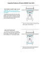
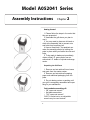
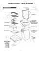
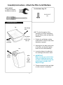
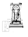
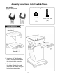
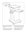
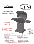
Formerly:
Now:
®
CFM Corporation
Assembly and
Owners manual
Model A052041
2004 Series
Portable
Gas Grill
ASSEMBLER / INSTALLER:
Leave these instructions with the consumer
.
CONSUMER / USER:
Read all of these instructions and keep them in a safe place for future reference.
FOR YOUR SAFETY
If you smell gas:
1 Shut off gas to the appliance.
2 Extinguish any open flame.
3 Open lid.
4 If odor continues, immediately call
your gas supplier or fire department.
FOR YOUR SAFETY
1 Do not store or use gasoline or other
flammable vapors and liquids in the
vicinity of this or any other appliance.
2 An unconnected liquid propane
cylinder should not be stored in the
vicinity of this or any other appliance.
Table of Contents
Page Number
Chapter One - INSTALLATION
4
Necessary Information
Choosing a Safe Location
Portable L.P. Gas Grills
Important Features of the Series 4000 LP Gas Grill
L.P. Gas Dealer Instructions
4
4
5-7
8
9
Chapter Two - ASSEMBLY INSTRUCTIONS
10
Identifying Parts
Attach Pillar to Grill Bottom
Assemble Base to Pillar
Install X-Brace
Install the Side Tables
Assemble Grill Lid
Installing the Internal Parts
Installing an L.P. Gas Cylinder
Connecting an L.P. Gas Cylinder
11
12 - 13
14 - 15
16 - 17
18 - 19
20 - 21
22 - 23
24
24 - 25
Formerly:
®
Now:
CFM Corporation
2695 Meadowvale Boulevard
Mississauga, Ontario L5N 8A3 Canada
(800) 668-5323
www.cfmcorp.com
Service Note: If you are experiencing difficulties or are dissatisfied with your purchase, please contact CFM at
the telephone number listed above prior to returning your grill to the store.
Model A052041 Series
Installation
Chapter 1
• Operating this or any gas-fired appliance in an enclosed area can produce a
build-up of carbon-monoxide, which could
result in injury or death.
Necessary Information to
Safely Use a Gas Grill.
2. Installation must conform with local
codes or, in the absence of local codes,
with either the National Fuel Gas Code,
ANSI Z223.1, NFPA 54 (USA), or
CAN/CGA-B 149.2, Propane Installation
Code (Canada) and CAN/CGA-B 149.1
Natural Gas Installation Code.
To check local codes, contact your local
gas dealer or gas company listed in the
Yellow Pages for recommended installation
procedures and regulations.
The gas fuel used by this product is
highly flammable and must be used in
a responsible and cautious manner.
It is your responsibility to assemble,
operate, and maintain your gas
barbecue grill properly.
!
3. This appliance is not intended to be
installed in or on a recreational vehicle
and/or boat.
4. Keep the barbecue grill at least 24
inches (61 cm) away from any combustible
construction.
• Do not use a grill under a ceiling or
cover where the heat or flame could cause
damage.
• Choose a level surface where the grill
is not facing directly into the wind.
• Avoid moving the grill during use.
If these instructions are ignored, there
is a possibility of a hazardous fire or
explosion which could result in property damage, physical injury or death.
Choosing a Safe Location for a
Gas Barbecue Grill.
5. The grill area must be clear and free
from combustible materials, gasoline, and
any other flammable liquids or vapors.
• Do not use lighter fluid or charcoal briquettes in a gas grill. The flow of combustion and ventilation air is not to be obstructed.
1. The gas barbecue grill may only be
used for cooking out-of-doors.
• Do not operate this barbecue in
garages, breezeways, sheds or any
enclosed area.
4
• Do not place combustible material,
such as cloth or plastic, on grill surface
during use.
• Do not lean on side tables or place
more than 15 pounds of weight on a side
table.
9. Make sure that the heat shield and
drip pan are in place under the grill bottom.
• Heat and hot drippings from cooking
food could damage the fuel supply system.
Portable L. P. Gas
Barbecue Grills
WARNING: Do not use natural gas in
an appliance designed for L.P. gas. Use
only liquid propane (L.P.) gas in an appliance designed for L.P. gas.
Do not store spare cylinders near grill.
• The ventilation openings of the cylinder
enclosure must be kept free and clear from
other debris.
L.P. Gas
Liquid Propane (abbreviated L.P.) gas
is stored under high pressure inside a
cylinder and will vaporize when released.
It is important that there are no leaky
connections on the grill fuel supply system. Refer to the Leak Testing section of
this manual.
6. Do Not store a spare L.P. gas cylinder
under or near this appliance.
• Do not store an L.P. cylinder in a building, garage or any other enclosed area.
Instead, store the cylinder outdoors in a
well ventilated area, away from people and
out of the reach of children.
7. NOT FOR USE BY CHILDREN.
• Place your barbecue grill in a location
away from children and pets.
• Do not leave grill unattended when in
use.
8. The outside of the barbecue grill will
become hot during use.
• To avoid burns, do not touch any hot
grill surface. If necessary, use a protective
glove when operating control knobs, tank
shut-off valve, or lid handle.
L.P. gas
cylinder not
included with
grill
The L.P. Fuel Supply System
5
2. The system has a thermal element that
will shut off the flow of gas between 240° F
and 300° F.
The L.P. FUEL SUPPLY SYSTEM
An L.P. gas grill requires a fuel delivery system made up of an L.P gas supply cylinder, a
fuel regulator with hose and a gas-control
valve.
3. The system has a flow-limiting device
which when activated, will limit the flow of
gas to 10 cubic feet per hour.
4. The pressure regulator and hose assembly provided is factory set at an outlet pressure of 11 inches water column (.4 lb. per
sq. inch).
Dual Burner Fuel-Control Valve
Type 1 Fuel Regulator
WARNING: Any attempt to adjust the
regulator is dangerous and could create
a situation causing personal injury or
property damage. Consult your L.P. gas
dealer if you think the regulator is not
working properly.
Valve Orifice
L.P. GAS SUPPLY CYLINDER
Fuel Supply
Hose
NOTE: AN L.P. CYLINDER IS NOT
INCLUDED WITH THIS GRILL MODEL.
An L.P. cylinder can be obtained at the
store where you purchased your grill or
from an authorized L.P. gas dealers.
The L.P. Fuel Supply System
(the fuel regulator and hose)
FUEL REGULATOR AND HOSE
The fuel regulator supplied is equipped with
a Type 1 coupling nut. Do not attempt to connect to any other L.P cylinder not equipped
with a mating Type 1 cylinder valve.
This grill is not to be used with any other cylinder connection device.
Cylinder Control Valve
L.P. Gas
Cylinder
The fuel regulator and hose assembly with
the Type 1 fitting supplied must be used with
the appliance. Do not use a hose and regulator assembly other than the one supplied with
the grill or a manufacturer’s replacement fuel
pressure regulator assembly.
The Type 1 connection system has the following features:
The L.P. Fuel Supply System
(L.P. gas cylinder)
1. The system will not allow gas to flow until a
positive connection has been made.
6
L.P. GAS CYLINDER SPECIFICATIONS
Allow only a qualified L.P. gas dealer to
fill or repair an L.P. gas-supply cylinder.
Any L.P. gas-supply cylinder used with
this grill must be approximately 12 inches
diameter and 18 inches high. The maximum fuel capacity must be 20 pounds of
propane. Full-cylinder weight should be
approximately 38 pounds (43.7 lbs. nominal
water capacity).
Inform the gas dealer if it is a new or used
cylinder to be filled. Caution the gas dealer
not to overfill the fuel cylinder.
After filling, have the gas dealer check for
leaks and that the relief valve remains free
to function.
The L.P. cylinder must have a shut-off
valve terminating in a Type 1 L.P gas-cylinder-valve outlet. A Type 1 compatible cylinder with a Type 1 cylinder valve has a positive seating connection that does not permit
gas flow until a positive seal has been obtained.
Have the gas dealer weigh cylinder after
filling to ensure that the cylinder is not overfilled.
DANGER:
a.) Do not store a spare L.P. gas cylinder
under or near this appliance.
The cylinder must be arranged for vapor
withdrawal. It must also include a Collar to
protect the cylinder valve. A safety-reIief
device having direct communication with
the vapor space of cylinder must be provided. This will expel high-pressure gas if the
cylinder is overfilled or overheated.
b.) Never fill the gas cylinder beyond 80
percent full.
c.) If the information in “(a.)” and “(b.)”
is not followed exactly, a fire causing
death or serious injury may occur.
All L.P. gas cylinders used with this appliance shall be constructed and marked in
accordance with the specifications for L.P.
gas cylinders of the U.S. Department of
Transportation (DOT) or the National Standard of Canada, CAN/CSA-B339,
Cylinders, Spheres and Tubes for
Transportation of Dangerous Goods; and
Commission, as applicable; and shall be
provided with a listed overfilling-prevention
device. Read labels on the L.P. gas-supply
cylinder.
TRANSPORTING A FULL CYLINDER
WARNING! Handle a full cylinder with
care. Gas is under high pressure.
You should transport only one cylinder at a
time. Transport the cylinder in an upright
and secure manner with control valve turned
off and the POL plug in place.
Do not transport cylinder in the passenger
compartment of a vehicle.
Do not leave cylinder in direct sunlight or in
a high-heat area such as a closed car trunk.
High-heat areas could cause the relief valve
to vent gas.
DANGER: Do not insert any foreign objects into the valve outlet. You may
damage the back check. A damaged
back check can cause a leak, which
could result in explosion, fire, severe
personal injury, or death.
Use a cylinder cap on cylinder-valve outlet
during transport and when the cylinder is not
connected to grill. Keep cylinder valve
closed when not in use.
7
Important Features of Series A052041 Gas Grills
HEAT SHIELD, GASKETS AND COLLAR
WARNING! Do not remove the heat
shield, gaskets, collar assembly from the
grill bottom.
Operating this grill without the heat shield,
gaskets, collar assembly attached to the grill
bottom would result in a hazardous situation
which could cause serious damage to property and possible physical injury.
Rear view of Series A052041 grill with the heat
shield, gaskets, collar assembly.
X-BRACE RETAINER WIRE
It is important to properly fit the X-Brace
retainer wire inside the pillar to provide additional stability. Remove the X-Brace only
when installing an L.P. gas supply cylinder.
Rear view of Series A052041 grill with the XBrace retainer wire shown in place.
8
Take These Instructions to the L.P. Gas Dealer.
When using a cylinder exchange, be sure the
exchanged cylinder is a Type 1 cylinder; a 510
POL cylinder will not fit a Type 1 regulator.
The L.P. gas cylinder has a Type 1 cylinder
valve with a back-check module in its outlet that
will not permit gas to flow until an evacuation
device is installed. To purge the L.P. gas cylinder, the back-check module must be opened
with an evacuation device.
FILLING AND PURGING TYPE 1 L.P. GAS CYLINDERS
DANGER! Purging and filling of L.P. Gas
cylinders must be performed by personnel
who have been thoroughly trained in accepted L.P. gas industry procedures. Failure to
follow this instruction may result in explosion, fire, severe personal injury, or death.
PURGING AND EVACUATION DEVICES FOR L.P. GAS
CYLINDER WITH TYPE 1 C YLINDER VALVES
A. Hose-end valve with a bleed port: Purging
can be accomplished using a hose-end valve
containing a bleed port, which also allows for
evacuation without the use of an adapter.
IMPORTANT: Purge new cylinders before filling. This tank is easily filled with a standard
CGA 510 POL filling connection.
B. Hose-end valve without a bleed port: When
a hose end valve does not have a bleed port, a
separate device must be used for evacuation.
C. Purging using a Type 1 connection: L.P. gas
cylinder evacuation can be accomplished during
each purging by using a Type 1 connection. The
Type 1 valve outlet has 1 5/16" external ACME
right-hand thread that will accept this connection.
CAUTION: After purging or filling an L.P. gas
cylinder, do not insert a POL plug into the valve
outlet. Insertion of this plug will prevent the
back-check from closing. Use ONLY the provided cap and strap attached to the outlet. Close
the cylinder valve knob before returning the
cylinder to the customer.
Example A
Filling a Type 1 Cylinder Valve
Example A: shows a CGA-510 POL fitting.
Example B: shows using a Type 1 POL fitting.
For proper purging procedures in the U.S.A.
refer to: Safety Bulletin NPGA #133, “Purging
L.P. Gas Cylinders,” and Safety Bulletin NPGA
#130, “Recommended Procedures for Filling
Cylinders.”
DANGER: Do not fill an L.P. gas cylinder
beyond 80% full. If this information is not
followed exactly, a fire causing serious injury
or death may occur.
Example B
9
Model A052041 Series
Assembly Instructions
Chapter 2
Getting Started
1. Please follow the steps in the order that
they are presented.
2. Assemble the grill where you plan to
use it.
3. You may want to place an old towel or
cloth at the assembly site to prevent nuts
and bolts from becoming lost.
4. Have a friend help. An assistant can
make the assembly easier by holding the
parts in place while you fasten the nuts and
bolts.
5. To be ready to barbecue immediately,
obtain a filled L.P. gas cylinder from an
authorized L.P. dealer or cylinder exchange
center.
Unpacking the Grill Parts
1. Remove and set aside all inner boxes
and parts from the master carton.
2. Remove and set aside all wrapping
paper and additional packaging from the
parts.
3. Do not destroy carton or packing until
your grill is completely assembled and operating to your satisfaction.
Tools needed to assemble grill:
• 3/8” open-end wrench*
• flat blade screwdriver
• 7/16" open-end wrench*
*HINT: A socket set or an adjustable
wrench may be used instead.
10
Assembly Instructions • Identify the Grill Parts
handle (1)
Locate these parts:
handle standoff (2)
warming rack (1)
grill lid (1)
cooking grid (1)
ceramic briquettes
( 1 package )
grill bottom
assembly (1)
rock grate (1)
(burner assembly, heat
shield, collar gasket
and collar installed)
left side table (1)
grease pan (1)
pillar (1)
right side table (1)
(knobs, ignitor, valve,
hose w/ regulator
installed)
base (1)
X-brace
wire (1)
master hardware
bag (1)
consisting of:
(1) "A" bag
(1) "B" bag
(1) "C" bag
(1) "D" bag
11
Assembly Instructions • Attach the Pillar to Grill Bottom.
tools needed:
3
⁄8" open-end wrench
flat-blade screwdriver
Use hardware bag “B”:
1/4-20 x 3/4”
(4)
Locate these parts:
top
back hinge
strut
grill bottom
(1)
shown rightside up
collar
assembly
HINT: For the first portion of the
assembly you will be assembling
the grill bottom, pillar and base upside-down.
1. Position the grill bottom casting
upside down so that the heat collar
assembly is upward.
2. Working from the back (open) side
of the pillar, set the pillar upside
down onto the collar assembly.
top
3. Locate the holes in the pillar bottom and align with holes in collar.
front
control
knobs
pillar
(1)
shown
rightside up
4. IMPORTANT:
Make sure the gas control valve
ends are inside the burner venturi tubes extending through the
grill bottom as shown. (See
Adjacent Page)
5. Thread screws into holes and tighten with a wrench / screwdriver.
12
pillar bottom
fuel supply hose w/
regulator
gas control valve ends
burner
venturi
tubes
collar
grill bottom back
back hinge strut
13
Assembly Instructions • Assemble Base to Pillar
tools needed:
3
⁄8" open-end wrench
7
⁄16" open-end wrench
Use hardware bag “A”:
1/4-20 x 3/4”
(6)
Locate this part:
1/4-20
(6)
top
back
front
locking
casters
base
(1)
shown
rightside up
1. Lock the pre-assembled casters on
base by pushing down on the latch.
2. Set the base upside-down on onto
the pillar bottom as shown on the
adjacent page, aligning holes in
base with holes in pillar.
3. Insert six bolts through the holes in
the pillar and base. Thread the
locking hex nuts onto bolts.
Tighten with a wrench and a flathead screwdriver.
assembled
pillar
and
bottom
casting
4. Locate the two black lead wires
inside the grill bottom. Press the
metal contacts of the loose ends of
the lead wires onto the metal pins
located on the base and side of the
ignitor unit.
back
14
base
back
top
pillar
black lead wires
heat
shield
bottom casting back
ignitor
unit
15
Assembly Instructions • Install X-Brace.
No tools needed.
Locate this part:
top bent
ends
1 Now with the help of an
assistant carefully turn the
grill assembly right-side-up.
2. IMPORTANT:
Inspect beneath the grill
bottom to check that the
control-valve ends are still
inside the burner venturi tubes.
X-brace
(1)
The valve ends must always be inside the burner
tubes for the grill to safely operate.
grill bottom as shown from below back.
16
ATTENTION PRODUCT ASSEMBLER:
Install the X-brace retainer wire across the back of the pillar for warranty validation.
UPPER
DETAIL
back
3. Position the wire ends “A” and “B” firmly into the pillar
corners behind the bolt heads and against the base.
(See Lower Detail.)
4. Complete the installation by snapping bent ends “C”
and “D” into the two holes in the pillar. (See Upper
Detail.)
5. When complete, the X-brace should be positioned as
shown in the lower right picture.
17
LOWER
DETAIL
Assembly Instructions • Install the Side Tables.
tools needed:
3/8" open-end wrench
7/16" open-end wrench
Use hardware bag “C”:
1/4-20
hex nut
(8)
Locate these parts:
left side table
assembly ( 1 )
right side table
assembly ( 1 )
1. Insert four 3/4" bolts through
holes in the support brackets of
the right side table assembly.
2. Attach the right side table to the
four holes located in the right
side of the grill bottom using the
locking hex nuts provided.
18
1/4-20 x 3/4” bolt
(8)
3. Insert four 3/4" bolts through holes in the
support brackets of the left side table
assembly.
HINT: Preformed hooks included on the right
side table assembly may be used to keep
cooking utensils (not included) at hand.
4. Attach the left side table to the four holes
located in the left side of the grill bottom
using the locking hex nuts provided.
CAUTION: Do not apply more than 15
pounds to either side table that could
unbalance and tip the grill.
19
Assembly Instructions • Assemble the Grill Lid
tools needed:
7/16" open-end wrench
flat-blade screwdriver
use
hardware bag “D”:
hairpin ( 2 )
hinge pin
1/4 x 1 1/8”
(2)
standoff
gasket
(2)
1/4-20
hex nut ( 2 )
Locate these parts:
handle
(1)
handle standoff
(2)
grill lid
(1)
1. Position the back of the lid so that the rear
holes are in line with the hinge struts on
the back of the grill bottom.
2. Gently set the grill lid onto the grill bottom.
20
1/4-20 x 3/4”
bolt ( 4 )
3. Hold the lid to align the hinge holes.
4. Insert a hinge pin through the hinge hole
in the lid and into the hole in the bottom
hinge strut.
4.
3.
5. After the hinge pin is in place, insert a
hair pin through the hole of the hinge pin
to secure it.
HINT: There is an air space between the
back of the lid and the grill bottom where
you can install the pins.
6. Repeat for the opposite side.
7. Raise the lid to attach the front handle.
8. Attach a handle standoff to the front of
the grill lid, as shown.
9. Insert one end of the handle into the hole
of the standoff.
10.Place other standoff onto handle and
while holding the handle in place assemble the opposite standoff to the lid in the
same manner.
21
5.
Assembly Instructions • Installing the Internal Grill Parts.
No tools are needed.
Locate these parts:
rock grate
(1)
ceramic
briquettes
( 1 box )
1. Place the single rock grate into
the grill bottom.
cooking grid
(1)
warming
rack
(1)
2. Open the package containing the
ceramic briquettes and place
them on the rockgrate.
22
3. It is important to properly arrange
all the ceramic briquettes onto the
rock grate to allow for good air flow
during use.
NOTICE THE SPACING:
The proper amount of briquettes
are supplied and there is no need
to add more. Some space between
the briquettes is necessary.
4. Set the porcelain coated cooking
grid on the front and back ledges
formed inside the grill bottom for
a level cooking surface.
5. Set the warming rack onto the
back of the cooking grid.
The grill assembly is now complete.
23
Model 4000 Series Replacement Parts
You may also write to:
Replacement parts are available direct
from our warehouse. Some components are
not available preassembled and may be
ordered separately. For convenience, the
following parts list is provided along with a
representation of the items listed. Charges
for replacement parts and shipping may
apply.
the Great Outdoors Grill Company®
7980 East American Drive
Joplin, Missouri U.S.A. 64804
PLEASE NOTE: All parts that meet the
warranty requirement will be shipped at nocharge via the discretion of the Customer
Service Department (ground shipments, US
Mail, or Parcel Post ONLY). Any Special
handling charges (i.e. Second Day,
Overnight, etc.) will be the responsibility of
the consumer.
For warranty replacements, proof of ownership and date of purchase is required.
Please call 888-869-5454 to receive a
return authorization number before returning
any grill components.
To order parts call toll free in the USA:
888-869-5454.
Parts Enclosed
Parts Enclosed
quantity
1
1
6
6
description
Main Hardware Bag
Hardware Bag “A”
1⁄4 x 20 x 3⁄4" Bolt
1⁄4 x 20 Hex Keps Nut
1
4
Hardware Bag “B”
1⁄4 x 20 x 3/4" Bolt
8
8
Hardware Bag “C”
1⁄4 x 20 x 3⁄4" Bolt
AM000105
1⁄4 x 20 Hex Keps Nut AM000904
2
2
4
4
2
Hardware Bag “D”
1⁄4 x 1 1⁄8" Hinge Pin
Hairpin
1⁄4 x 20 x 3/4" Bolt
1⁄4 x 20 Hex Keps Nut
Handle Gasket
1
1
part number
AM000404
quantity
1
1 package
1
1
1
1
2
1
1
AM000105
AM000904
AM000105
description
Grate
Ceramic Briquettes
Cooking Grid
Warming Rack
Grill Lid
Lid Handle
Handle Standoffs
Aluminum Drip Pan
X-Brace Cylinder Retainer
Preassembled Components
1
Base Assembly
1
Pillar Assembly
1
Bottom/Burner Assembly
1
Right Side Table Assembly
1
Left Side Table Assembly
AM000908
AM000909
AM000105
AM000904
AM000704
34
part number
AF000203
AQ000103
AF000104
AF000304
TOP350-BLK
AP000102
AZ000802
AI000302
AF000404
Breakdown of Preassembled Components
Bottom/Burner Assembly
quantity
description
1
Bottom/Burner Assembly
consisting of:
1
Cast Iron Burner
1
Venturi Tube w/gasket
8
#8-32 x 7/16" Screw
1
Bottom Grill Casting
1
Collar
1
Heat Shield
1
Forward Gasket
2
Side Gasket
4
1/4 x 20 x 1 1/4” bolt
8
Speed Nuts
part number
AZ001505
AZ000507
AM000603
BTM350-BLK
COLLAR C/P BLK
AI000204
AM000911
AM000910
AM000107
AM000906
Pillar Assembly
1
Pillar Assembly
consisting of:
1
Pillar SF
2
10 x 24 x 1/2" Bolt
1
Valve/Regulator/Hose
1
Push Button Igniter
2
Control Knobs
AH000401
AM000103
AL000104
AN000304
AZ000704
Side Table Assemblies
1
Right Side Table Assembly
consisting of:
1
R.H. Bracket
SDTBL BRKT R BLK
1
L.H. Bracket
SDTBL BRKT L BLK
1
Right Side Table (w/hooks) AH000403
4
Screws
AM000206
1
Left Side Table Assembly
consisting of:
1
R.H. Bracket
SDTBL BRKT R BLK
1
L.H. Bracket
SDTBL BRKT L BLK
1
Left Side Table (cup holder) AH000404
4
Screws
AM000206
Base Assembly
1
Base Assembly
consisting of:
1
Base SF
2
Locking Caster
2
Caster
AH000402
AH000303
AH000305
35