1
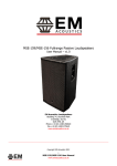
QLIGHT™ SERIES
USER MANUAL
TQ-230
TQ-308
TQ-310
TQ-315
TQ-445
TQ-425
TQ-115
Turbosound Ltd.
Star Road, Partridge Green
West Sussex RH13 8RY United Kingdom
Tel: +44 (0)1403 711447 Fax: +44 (0)1403 710155
Web: www.turbosound.com
Issue 1.2 July 2006
Copyright © 2006 Turbosound Ltd.
user manual
QLight™ series
CONTENTS
Thanks ................................................................................................................................................. 4
Unpacking the QLight™ series loudspeaker ..................................................................................... 4
Features ....................................................................................................................................................5
Product Range Summary.........................................................................................................................6
TQ-230 ................................................................................................................................................. 6
TQ-308 ................................................................................................................................................. 6
TQ-310 ................................................................................................................................................. 6
TQ-315 ................................................................................................................................................. 6
TQ-445 ................................................................................................................................................. 6
TQ-425 ................................................................................................................................................. 7
TQ-115 ................................................................................................................................................. 7
System requirements...............................................................................................................................8
Amplifier considerations.................................................................................................................... 8
Equalisation ........................................................................................................................................ 9
Dispersion ........................................................................................................................................... 9
Converging Elliptical Waveguide™ ..................................................................................................10
Mounting and Fixing..............................................................................................................................11
Rigging Hardware..............................................................................................................................11
Summary of rigging options ............................................................................................................17
Permanent installations ....................................................................................................................17
Choosing the best location ...............................................................................................................18
Maintenance ...........................................................................................................................................19
TQ-230 - Removal of the drivers.......................................................................................................19
TQ-308/TQ-310/TQ-315 – Removal of the drivers ............................................................................19
TQ-445 - Removal of the 12”/1” driver.............................................................................................19
TQ-115 - Removal of the 15” driver..................................................................................................20
TQ-425 – Removal of the 15” driver(s) .............................................................................................20
TQ-445 - Removal of the midrange drive unit and horn assembly ................................................20
Appendix A .............................................................................................................................................21
Spares and accessories .....................................................................................................................21
Flying accessories..............................................................................................................................22
Appendix B: Technical specifications....................................................................................................24
Appendix B: Technical specifications....................................................................................................24
Appendix C: Warranty............................................................................................................................26
TQ series manual
page 2
user manual
QLight™ series
Limited Warranty .............................................................................................................................. 26
Warranty Coverage........................................................................................................................... 26
Shipping ............................................................................................................................................ 26
Incidental and consequential damages ........................................................................................... 27
Limitation of implied warranties...................................................................................................... 27
TQ series manual
page 3
user manual
QLight™ series
Introduction
Thanks
Thank you for choosing a QLight™ series loudspeaker product for your application. Please spare a
little time to read the contents of this manual, so that you can obtain the best possible
performance from this unit.
All TURBOSOUND products are carefully engineered for world class performance and reliability.
If you would like further information about this or any other TURBOSOUND product, please
contact us. Detailed product information is available on our web site at www.turbosound.com
We look forward to helping you in the near future.
Congratulations, you have just purchased a professional loudspeaker system from the renowned
Turbosound range, designed to give you the best in audio quality and many years of reliable,
trouble free operation. It offers superior audio quality, unsurpassed vocal projection, full technical
documentation including EASE data, and comprehensive rigging and flying hardware options.
Please read through this manual carefully before you attempt to operate the loudspeaker system.
It contains valuable information enabling you to quickly and easily set up and connect the
loudspeakers, important system and set-up checks together with positioning and mounting
instructions.
Unpacking the QLight™ series loudspeaker
After unpacking the unit please check carefully for damage. If damage is found, please notify the
carrier concerned at once. You, the consignee, must instigate any claim. Please retain all
packaging in case of future re-shipment.
TQ series manual
page 4
user manual
QLight™ series
FEATURES
•
Superb audio quality: carefully designed and matched loudspeaker drive units are used
to give you exceptional performance and many years of reliable, trouble free operation.
•
Ease of use: QLight™ series products are exceptionally easy to set up and use with the
minimum of technical knowledge required.
•
Multi-way designs: the exclusive use of cone transducers in the mid frequency bands
guarantees seamless crossover regions, as well as greater power handling, lower
distortion and less mechanical stress.
•
Custom-designed drive units: a special 12”/1” co-axial driver was developed for the
TQ-445 which allows this three-way enclosure to exceed the performance of equivalentsized traditional two-way designs.
•
Wide dynamic range: all drive units are capable of handling large amounts of amplifier
power in order to achieve high SPL without sacrificing headroom.
•
Controlled dispersion: QLight™ series mid/high frequency enclosures feature controlled
dispersion patterns which minimise room reflections and focus sound coverage directed
at audience areas without overspill.
•
Aligned components: mid and high frequency components are physically aligned to
ensure perfect time arrival at the listener’s ear.
•
Solid construction: all QLight™ series cabinets are built from high grade birch plywood,
rebated, screwed and glued together for maximum rigidity and durability.
•
Integral rigging points: fitted as standard, enabling use with optional Turbosound flying
hardware for all types of fixed installations and mobile sound reinforcement applications.
•
Compact enclosures: the overall dimensions of QLight™ series enclosures have been
kept as small as possible to enable portable use as well as fitting easily into permanent
installations.
TQ series manual
page 5
user manual
QLight™ series
PRODUCT RANGE SUMMARY
TQ-230
The TQ-230 is a compact passive 2-way loudspeaker with two 5” woofers designed for foreground,
background and in-fill music applications as well as a theatre under-balcony loudspeaker. Its wide
horizontal dispersion and a rotatable high frequency horn enable horizontal or vertical orientation.
Intended for portable use as well as for fixed installations, the TQ-230 is provided with rigging
points to enable use with eyebolts, wall and ceiling brackets, swivel brackets and pole brackets.
TQ-308
The TQ-308 is a compact 8” quasi-trapezoidal passive 2-way loudspeaker designed for use with
Turbosound digital controllers such as the LMS-D4 or LMS-D6. Its primary application is as a small
and unobtrusive speech and music system ideal for corporate rentals or permanent installs such
as theatres, bars and small clubs. Its rotatable 100° x 60° HF horn allows considerable flexibility of
physical orientation as well as audience coverage options. Flying and mounting options include
pole mounts, pole brackets and speaker stands; integral rigging points for use with Turbosound
and OmniMount™ wall and ceiling brackets, and swivel brackets.
TQ-310
The TQ-310 is a full range 10” quasi-trapezoidal passive 2-way loudspeaker designed for use in
mobile speech and music sound reinforcement applications with LMS-D4 or LMS-D6 digital
controllers, including use as a floor monitor. It is also ideal for use in a wide range of fixed
installations using various rigging options which include adjustable wall and ceiling brackets,
swivel brackets, flying frames and RT-767 ring type fly points.
TQ-315
A switchable bi-amp/passive 15” full range quasi-trapezoidal 2-way loudspeaker that doubles as
front-of-house and floor monitor applications when used with Turbosound LMS-D4 or LMS-D6
digital controllers. Its 80° x 55° HF horn pattern is rotatable through 90° to allow a range of
coverage options. Fixed installs are catered for by a range of rigging options, including wall and
ceiling brackets, flying frames, swivel brackets and RT-767 ring type fly points
TQ-445
The TQ-445 is a compact three-way bi-amped full range enclosure that offers unprecedented levels
of audio clarity and definition. It combines a co-axial LF/HF driver with a proprietary 6.5" midrange
cone transducer in a vented trapezoidal enclosure, providing focused directivity and considerable
vocal projection. The TQ-445 is designed for use with the LMS-D6 digital loudspeaker
management system, which provides model-specific crossover, equalisation and limiting
functions. In order to extend the effective bass frequency range of the loudspeaker by a further
octave the use of the complementary TQ-425 subwoofer is recommended.
TQ series manual
page 6
user manual
QLight™ series
TQ-425
The TQ-425 is a front loaded, double neodymium 15” vented subwoofer designed to combine with
QLight™ series enclosures to give a high quality, full range sound reinforcement system ideally
suited to all corporate, industrial, theatre and audio visual applications. When used with the LMSD6 digital crossover it will reproduce high sound pressure levels at bass and sub-bass frequencies.
The TQ-425 is equipped with a pole mount socket to enable QLight™ series mid-high loudspeakers
to be used at an optimum height above the subwoofer.
TQ-115
The TQ-115 is a front loaded, single neodymium 15” vented subwoofer designed to combine with
QLight™ series enclosures to give a high quality, full range sound reinforcement system ideally
suited to all corporate, industrial, theatre and audio visual applications. When used with the LMSD6 digital crossover it will reproduce high sound pressure levels at bass and sub-bass frequencies.
The TQ-115 is equipped with a pole mount socket to enable QLight™ series mid-high loudspeakers
to be used at an optimum height above the subwoofer.
TQ series manual
page 7
user manual
QLight™ series
SYSTEM REQUIREMENTS
QLight™ series passive loudspeaker enclosures require only one amplifier channel for correct
operation, the frequency splitting between the low frequency driver and the high frequency driver
being accomplished by the internal passive crossover network built into each enclosure. If
subwoofer enclosures are used as part of a bi-amplified system in conjunction with QLight™
series 2-way enclosures to extend low frequency response, additional amplifier channels and
external electronic crossovers will be required. The Turbosound LMS-D6 and LMS-4 digital
loudspeaker management systems are recommended for this purpose, as well as other
professional quality digital controllers.
Bi-amplified loudspeaker enclosures require the use of one amplifier channel per frequency band
for correct operation. Frequency splitting between the low frequency driver, and the mid and high
frequency section drivers is accomplished by an external electronic crossover; while frequency
splitting between the mid frequency driver and the high frequency driver in 3-way models (TQ445) is handled by an internal passive crossover.
Dedicated subwoofer enclosures require an additional amplifier channel when used as part of an
extended frequency system. Frequency splitting between it and a QLight™ series mid-high
enclosure is accomplished by an external crossover. Turbosound digital loudspeaker management
systems are recommended for this purpose.
Amplifier considerations
Turbosound speaker enclosures should be driven by high quality power amplifiers designed for
true professional use. Such amplifiers will have balanced inputs, DC and RF fault protection, and
well designed cooling systems for reliability. Turbosound power amplifiers such as the T-45 and T25 are recommended for this purpose.
The program power listed in the loudspeaker’s technical specification is the best guide to the size
of amplifier required for general purpose applications. The amplifier should therefore be capable
of delivering long term broadband power equal to the loudspeaker’s program power rating at the
loudspeaker’s stated nominal impedance. This approach allows sufficient headroom to generate
good dynamic range.
RECOMMENDED AMPLIFIER POWER RATINGS:
The amplifier's rated r.m.s. continuous power output (20Hz – 20kHz, per
channel) should be equal to the program power handling of the
loudspeaker at its nominal impedance.
TQ series manual
page 8
user manual
QLight™ series
In general, the more powerful the amplifier, the better it will sound, provided that it is not driven
into sustained clipping. It should be understood that overdriving an insufficiently powered
amplifier is more likely to cause loudspeaker damage – the total energy in a heavily clipped signal
is far higher than in an unclipped signal – than operating a more powerful amplifier within its
ratings.
One loudspeaker management system can be used to feed several amplifiers as long as all the
amplifiers are the same (or have the same gain ratings). More than one loudspeaker management
system may be required if the amplifiers are of different gain or type. Please contact your dealer if
you require help in this area.
Equalisation
QLight™ series enclosures are designed to provide smooth and even frequency response. They do
not need excessive amounts of external equalisation to overcome the sonic deficiencies often
found in many lesser designs.
Should an extended frequency response be required at more than moderate sound pressure
levels, the use of complementary Turbosound subwoofer enclosures is strongly recommended.
In order to compensate for the room acoustics, Qlight™ series enclosures require only minimal
equalisation. As in any system, over-equalisation introduces phase shifts, distortion and a
reduction in headroom, usually causing more problems than it cures. Under most circumstances a
1/3 or 1/2 octave graphic equaliser will generally be adequate, with the fader settings applied
smoothly and as little as possible for the required room compensation. Most rooms will have
resonances that will be excited at particular frequencies needing some cut to help tame the sound.
These problems are most pronounced at the lower frequencies where loudspeakers generally
exhibit very little directional control. If you find that the system needs a lot of boost at lower
frequencies you may need additional sub-bass units. It is good practice to use as little equalisation
as possible, aiming to cut frequencies rather than adding large amounts of boost.
Dispersion
Qlight™ series loudspeakers fall broadly into two categories of dispersion pattern: wide and
medium. While a wide horizontal coverage pattern of approximately 80° to 100° is appropriate for
a majority of small to medium venues, one of the design features of the TQ-445 is a tightly
controlled 60º horizontal by 40º vertical dispersion pattern at mid and high frequencies. This gives
many user advantages and eases placement decisions, being essentially a point and shoot system.
The more focused directivity results in greater projection capabilities, making the TQ-445 very
suitable for theatre and small auditorium applications. Remember that a 60º horizontal polar
pattern equals an angle of 30º either side of the centre line at which the sound pressure level is
TQ series manual
page 9
user manual
QLight™ series
6dB down with respect to centre, (averaged over the whole frequency range of the loudspeaker).
Converging Elliptical Waveguide™
A design feature of the TQ-308, TQ-310 and TQ-315 is the Converging Elliptical Waveguide™
(CEW™), available in two directivity patterns: 100° x 60° and 80° x 50°. This gives many user
advantages. The comparatively short flare length allows the HF and LF components to be
physically aligned in the cabinet, so ensuring coherent arrival at the listener’s ear irrespective of
distance from the loudspeaker. The elliptical format shapes the wavefront smoothly, and
eliminates reflections in the throat area. Additionally this design does not suffer from the
distortion typical of horns employing diffraction edges.
The waveguides can be removed and rotated through 90º in the cabinet, which allows the
products to be installed in either vertical or horizontal formats while retaining the required
coverage.
To rotate the horn, first remove the grille by undoing the countersunk Allen head screws which
retain the grille from the sides of the cabinets. Remove the four screws holding the horn flange in
place. Lift the horn and driver assembly out, rotate it through 90º and replace the fixing screws.
Replace the grille.
TQ series manual
page 10
user manual
QLight™ series
MOUNTING AND FIXING
Rigging Hardware
A versatile range of mounting hardware is available that allows enclosures to be used in a variety
of ways, in either mobile applications or permanent installations.
A top hat stand type fitting is fitted to the base of
QLight™ series full range and mid-high cabinets
for use with 35mm diameter loudspeaker stands. A
pole mount socket is also fitted to the top of the
QLight™ sub-bass cabinets. This allows two
enclosures to be used together as an extended
frequency range system as shown here with the
TQ-445 mounted above the TQ-425 on the optional
35mm diameter straight pole. This enables a
minimum footprint for the system and ensures the
correct vertical distance between cabinets.
Internal M10 threaded rigging points are provided in several
locations on the cabinet – generally on the top, bottom, sides
and back – enabling enclosures to be suspended quickly and
inexpensively using optional M10 shoulder eyebolts.
Downward inclination of the enclosure can be adjusted using
an additional rigging point on the rear of the cabinet. Note:
these rigging points are intended to hang a single box only and
must NOT be used to rig a second enclosure in a vertical
column.
TQ series manual
page 11
user manual
QLight™ series
RT-767 ring type flying points. Rigging points
are provided on the top and rear of the TQ-310
and TQ-315 for use with optional RT-767 rings,
enabling cabinets to be rigged in permanent
installations and for mobile applications.
Downward inclination of the enclosure can be
adjusted using the third RT-767 rigging point on
the rear of the cabinet
Swivel brackets provide a means of wall mounting some QLight™ series enclosures (TQ-308, TQ310 and TQ-315) in a horizontal or vertical orientation. They are attached to the box using the
integral pole mount fitting at the bottom and the M8 internal rigging point on the top of the
cabinet. For applications requiring a horizontal format, an additional scaffold clamp assembly can
be used with swivel brackets for attaching to lighting grids.
TQ series manual
page 12
user manual
QLight™ series
Wall brackets are available for most Qlight™ series enclosures in different load ranges according
to the weight of the cabinet. Two examples are shown below: the WB-10 wall bracket with a TQ230 and the WB-20A with a TQ-310. Wall brackets can be dis-assembled to simplify installation and
are supplied with the necessary fixings (except wall fixings). Remove the countersunk screws in
the back of the box that correspond to the bolt hole pattern in the speaker plate, and attach it using
the bolts provided with the hardware. Mount the wall plate in the desired position using suitable
wall fixings. Locate the captive bolt on the speaker plate in the hole provided on the wall plate,
position and angle the loudspeaker for optimum room coverage and tighten the nylock nuts.
WB-10/TQ-230
WB-55A/TQ-310
Ceiling brackets are available for the TQ-230, TQ-308, TQ-310
and TQ-315. As with Turbosound wall brackets, they can be
dis-assembled to simplify installation and are supplied with
the necessary fixings (except wall fixings). Remove the
countersunk screws in the back of the box that correspond to
the bolt hole pattern in the speaker plate, and attach it using
the bolts provided with the hardware. Attach the ceiling plate
using suitable fixings. Position and angle the loudspeaker for
optimum room coverage and tighten the nylock nuts.
TQ series manual
page 13
user manual
QLight™ series
Side-mounted flying strips can be fitted to the
sides of TQ-445 enclosures by removing the
countersunk bolts on the top and sides of the
cabinet and replacing them with the M10 bolts
supplied with the hardware. Two flying strips are
required for each enclosure; one attached to each
side. This method offers a simple and cost
effective way of flying single enclosures in
permanent installations. Enclosures may also be
arranged in a vertical column by coupling the
flying strips together using QL-75 quicklinks or
shackles. Turbosound flying strips are
individually load tested. When used in this way
the load is taken through the flying strips rather
than through the woodwork of the enclosure.
Side-mounted flying strips can be fitted to the sides of Qlight™ series subwoofer cabinets to
enable subwoofer enclosures to be flown as part of a permanent installation. Two different lengths
of flying strips are optionally available for flying the enclosure in either a vertical or horizontal
orientation. These are fitted by removing the countersunk bolts on the top and sides of the cabinet
and replacing them with the M10 bolts provided with the hardware. Two flying strips are required
for each enclosure. This method offers a simple and cost effective method of flying single or
multiple enclosures, with the load being taken through the steel strips rather than through the
woodwork of the enclosure. Enclosures may be arranged in a vertical column if required by
coupling the flying strips together using QL-75 quicklinks or shackles. Turbosound flying strips are
load tested.
WARNING: Rigging eyebolts must not be used for flying this enclosure. You must use the optional
Turbosound steel flying strips described above.
TQ series manual
page 14
user manual
QLight™ series
Single point mount options include a universal FB-12 flybar assembly for
use with the TQ-445 and this enables the use of several different fixing
methods. The illustration at right shows the FB-12 with three different
methods of suspending the TQ-445 cabinet: a unilock fitting; a scaffold
clamp; and a pick-up point adapter.
To attach the flybar first remove the threaded plastic plugs filling the
rigging points on the top of the cabinet. Fit the flybar to the cabinet
using the captive M10 shoulder eyebolts supplied with the flybar
assembly. There are 12 attachment points equally spaced along the
length of the spine of the flybar. Depending on which point is chosen for
the given attachment system, a wide range of downward inclination
angles can be achieved over a range of approximately 70 degrees. The
design of the flybar even allows for upward angles, for example for
coverage of balconies that are higher than the loudspeaker location.
The FB-12 flybar assembly comes supplied with a U-6 Unilock fitting,
which provides a single attachment point. The point at which the Unilock is attached to the flybar
determines the vertical angle of the loudspeaker as shown in the table following.
A pick-up point adapter offers a further single attachment point. This option provides fast
adjustment of vertical angle. The point at which the eyebolt adapter is attached to the flybar
determines the vertical angle of the loudspeaker as shown in the table following.
An aluminium scaffold clamp is attached to the fly bar by means of a simple clevis coupler. It is
designed to rotate horizontally through 360° in order to enable accurate positioning of the
loudspeaker. The point at which the scaffold clamp is attached to the fly bar determines the
vertical angle of the loudspeaker as shown in the table following.
TQ series manual
page 15
user manual
QLight™ series
The following table gives the predicted downward angle of TQ-445 enclosures when using the FB12 flybar.
Attachment position
Vertical angle (negative angle denotes upwards)
Hole number 1 (front of cabinet)
-29°
Hole number 2
-23°
Hole number 3
-17°
Hole number 4
-10°
Hole number 5
-3°
Hole number 6
4°
Hole number 7
11°
Hole number 8
18°
Hole number 9
24°
Hole number 10
30°
Hole number 11
35°
Hole number 12 (rear of cabinet)
40°
Flying frames enable Qlight™ series loudspeakers to be suspended from ceilings and lighting
grids with virtually unlimited angle adjustment, including upward angles. These are available for
the TQ-308, TQ-310, TQ-315 and TQ-445. To fit, remove the countersunk screws from the sides of
the cabinet, position the frame and secure with the bolts provided. Angle the loudspeaker as
required and tighten the handwheels.
FH-308 flying frame
TQ series manual
page 16
user manual
QLight™ series
Summary of rigging options
Eyebolts
TQ-230
TQ-308
M10
M10
Rings
TQ-310
TQ-315
RT-767
RT-767
TQ-445
TQ-425
TQ-115
M10
M10
M10
Wall
WB-10
WB-20A
WB-20A
WB-55A
Ceiling
CB-10
CB-20A
CB-20A
CB-55A
Swivel
SB-308
SB-310
Frame
FH-308
FH-310
FH-315
FH-445
PB-55
PB-55
PB-55
PB-55
Pole
PB-55
Strips
FS-445
Single
FB-12
FS-425
point
Permanent installations
Any installation, whether temporary or permanent, must be securely attached to the structure of
the building using chain, steel wires or web straps which are certified and load rated for the
purpose. The combined weight of the sound system, its cables and the rigging system must be
safely carried by the points at which attachment is made to the building or structure. Great care
must be taken in selecting the attachment points and methods, being absolutely sure of the load
carrying capacity of points chosen.
NOTE: The rigging of loudspeaker systems is an extremely serious matter with potentially lethal
consequences should anything go wrong. It is of vital importance that you, or other people rigging
TQ series manual
page 17
user manual
QLight™ series
the system, are suitably qualified to do so and have a full understanding of all the factors involved
with safety as a number one priority. Turbosound accepts no responsibility for any accident,
damage or failure of any rigged system. This rigging information is specifically related to the
requirements of Qlight™ series enclosures only. For more detailed information on the whole topic
of rigging various handbooks are available. If you are in any doubt contact your Turbosound
dealer who will be able to refer you to an experienced rigging company.
Choosing the best location
When using any QLight™ system, certain room parameters will affect the resultant sound quality
and coverage. For example, any boundary like a wall or floor will lift certain frequencies. If you are
placing the unit in a corner then a lift at the bass end is to be expected and it may sound rather
boomy. This can be compensated for moving the speaker or cutting low frequencies with a
graphic equaliser.
When speakers are flown in free space then boundary effects are minimised. The result is a
smooth frequency response without any boost at odd frequencies, but the bass end may appear
subjectively light. In this case increase the sub-bass level to bring the low end up.
The relationship between sound pressure level and distance is an “inverse square law” so
remember that every time the distance from the sound source is doubled the sound level
decreases by 6dB. For every 3dB increase of speaker output you need a doubling of input power
and you can work out the wattage input needed to give the required SPL levels at various
distances from the loudspeaker(s).
TQ series manual
page 18
user manual
QLight™ series
MAINTENANCE
If any of the drive units should cease functioning and needs a replacement recone you are advised
to remove the faulty unit from the cabinet and send it to a professional recone service authorised
to recone Turbosound loudspeakers. This will ensure the continued high performance of your
QLight™ series product.
TQ-230 - Removal of the drivers
The grille is secured in place with four flange head screws underneath the grille foam, at the top
and bottom of the cabinet. To remove the grille, remove these screws and lift the grille away from
the cabinet. The 5” woofers can now be removed from the cabinet by undoing the four screws
holding the speaker in place. Disconnect the woofer(s) making note of the polarity for later
reconnection.
To access the high frequency driver, remove the grille as above. Release the high frequency horn
and driver assembly by undoing the four screws securing the horn flange to the baffle.
TQ-308/TQ-310/TQ-315 – Removal of the drivers
The grilles on these cabinets are held in place by three countersunk Allen head screws on each
side, accessible from the sides of the cabinet. Remove these screws using the Allen key provided
with your product and lift the grille away from the cabinet. The woofer retaining screws will now
be visible and can be removed. Disconnect the driver(s) making note of the polarity for later
reconnection.
With the grille removed you can now access the HF horn and driver assembly by unscrewing the
four cap head screws securing the horn flange to the baffle. Disconnect the compression driver,
making note of the polarity for later reconnection.
TQ-445 - Removal of the 12”/1” driver
Unscrew the eight countersunk screws from the two vertical battens that hold the protective grille
in place. Be careful when removing the grille as it is under tension and may spring outwards when
released. Set the battens, grille and fixing screws aside for later re-assembly.
Undo the eight M6 x 30mm Allen head bolts holding the driver in place and carefully pull it out
and away from the cabinet. WARNING - this unit is heavy! You will notice that the 1” high
frequency driver is attached to the back of the 12” low frequency driver by its screw adapter.
Disconnect the cables from both HF and LF units and completely remove the driver assembly from
the cabinet. Make a note of the driver polarity for later reconnection.
Separate the drive units by unscrewing the high frequency driver anti-clockwise and lift it away
from the low frequency driver. Depending on which section needs servicing, the appropriate drive
TQ series manual
page 19
user manual
QLight™ series
unit should be returned to an authorised Turbosound service centre. To reinstate the drivers,
simply reverse the above procedure making sure you observe the correct polarity when
reconnecting the cables back into the terminals of the drive units.
TQ-115 - Removal of the 15” driver
Remove the countersunk Allen head screws retaining the grille from the cabinet sides and lift the
grille away. Undo the M6 Allen head bolts holding the driver in place and carefully pull it out and
away from the cabinet. Disconnect the cables from the drive unit and completely remove the
driver from the cabinet. Make a note of the driver polarity for later reconnection. To reinstate the
driver, simply reverse the above procedure making sure you observe the correct polarity.
TQ-425 – Removal of the 15” driver(s)
Unscrew the countersunk screws from the four battens that hold the protective grille in place. Set
the battens, grille and fixing screws aside for later re-assembly. Undo the M6 Allen head bolts
holding the driver(s) in place and carefully pull them out and away from the cabinet. Disconnect
the cables from the drive unit and completely remove the driver from the cabinet. Make a note of
the driver polarity for later reconnection. To reinstate the driver(s), simply reverse the above
procedure making sure you observe the correct polarity when reconnecting the cables back into
the terminals of the drive units.
TQ-445 - Removal of the midrange drive unit and horn assembly
Unscrew the countersunk screws from the two vertical battens holding the protective grille in
place. Be careful when removing the grille as it is under tension and may spring outwards when
released. Set the battens, grille and fixing screws aside for later re-assembly.
Remove the #6 x 1 ½” countersunk woodscrews securing the rear panel of the cabinet, or the four
bolts securing the amplifier module. The M10 bolt securing the midrange driver will now be
accessible in a recess in the enclosure rear panel. Using a 17mm socket, unscrew the bolt and set
aside for later re-assembly.
The midrange horn is secured through the mounting flange with four #10 x 1 1/2” countersunk
wood screws. Unscrew these and lift out the horn and driver assembly. Disconnect the cables,
making a note of the polarity, and carefully lift the driver clear.
For any other servicing requirements please contact your Turbosound dealer or authorised service
centre.
TQ series manual
page 20
user manual
QLight™ series
APPENDIX A
Spares and accessories
CD-114
1” (25mm) HF compression driver
TQ-445
CD-110
1” (25mm) HF compression driver
TQ-308, TQ-310
CD-211
1.4” (35mm) HF compression driver
TQ-315
LS-1018
10” (254mm) LF loudspeaker
TQ-310
LS-1214
12” (305mm) LF loudspeaker
TQ-445
LS-1526
15” (381mm) LF loudspeaker
TQ-425, TQ-115
LS-1520
15” (381mm) LF loudspeaker
TQ-315
LS-50
5” (127mm) LF loudspeaker
TQ-230
LS-6505
6.5” (165mm) MF loudspeaker
TQ-445
LS-8091
8” (203mm) LF loudspeaker
TQ-308
RC-1018
Recone kit for LS-1018
TQ-310
RC-1214
Recone kit for LS-1214
TQ-445
RC-1526
Recone kit for LS-1526
TQ-425, TQ-115
RC-1520
Recone kit for LS-1520
TQ-315
RC-50
Recone kit for LS-50
TQ-230
RC-6505
Recone kit for LS-6505
TQ-445
RD-114
Replacement diaphragm
TQ-445
RD-110
Replacement diaphragm for CD-110
TQ-308, TQ-310
RD-211
Replacement diaphragm for CD-211
TQ-315
RD-25
Replacement diaphragm for TW-25
TQ-230
TW-25
1” compression driver
TQ-230
TQ series manual
page 21
user manual
QLight™ series
Flying accessories
TQ series manual
page 22
BS-445
Biscuit
TQ-445
EB-10
M10 shoulder eyebolt
TQ-230/308/445/425/115
FB-12
Universal fly bar assembly
TQ-445
FF-445
Flying strips (2 required per enclosure)
TQ-445
FF-425L
Flying strips (2 required per enclosure) vertical
TQ-425
FF-425S
Flying strips (2 required per enclosure) horizontal
TQ-425
FH-308
Flying frame
TQ-230
FH-310
Flying frame
TQ-310
FH-315
Flying frame
TQ-315
FH-445
Flying frame
TQ-445
PP-445
Pick-up point adapter
TQ-445
RT-767
Ring type flypoints (set of 3)
TQ-310/315
TS-445
Tilting strap
TQ-445
U-6
Unilock
TQ-445
user manual
QLight™ series
TQ series manual
page 23
user manual
QLight™ series
APPENDIX B: TECHNICAL SPECIFICATIONS
Dimensions
Net weight
Power handling
Sensitivity
TQ-230
TQ-308
TQ-310
TQ-315
528 x 210 x 200mm
464 x 270 x 301mm
525 x 319 x 277mm
691 x 443 x 381mm
20.8” x 8.3” x 7.9”
18.3” x 10.6” x 9.5”
20.7” x 12.5” x 10.9”
27.2” x 17.4” x 15”
9.5 kgs
11.5 kgs
21 kgs
32.5 kgs
20.9 lbs
25.3 lbs
46.2 lbs
71.5 lbs
125 watts rms
250 watts rms
350 watts rms
680 watts rms
250 watts program
500 watts program
700 watts program
1360 watts program
90dB
96dB
96dB
99dB
70Hz – 20kHz
68Hz – 20kHz
65Hz – 20kHz
55Hz – 20kHz
100°h x 60°v
100°h x 60°v
100°h x 60°v
80°h x 50°v
120dB
129dB
130dB
136dB
(2) Neutrik Speakon
(2) Neutrik Speakon
(2) Neutrik Speakon
(2) Neutrik Speakon
NL4MP
NL4MP
NL4MP
NL4MP
(1w @ 1m)
Frequency
response
(±4dB)
Nominal
dispersion
(@ -6dB points)
Maximum SPL
(peak)
Connectors
TQ series manual
page 24
user manual
QLight™ series
TQ-445
TQ-425
TQ-115
588 x 409 x 363mm
836 x 511 x 632mm
559 x 450 x 578mm
23.1” x 16.1” x 14.3”
32.9” x 20.1” x 24.9”
22” x 17.7” x 22.8”
30 kgs
54 kgs
30.1 kgs
66 lbs
118.8 lbs
66.2 lbs
LF: 600watts rms
800 watts rms
400 watts rms
1200 watts program
1600 watts program
800 watts program
103dB
100dB
96dB
75Hz – 20kHz
55Hz – 200Hz
70Hz – 200Hz
60°h x 40°v
n/a
n/a
Maximum SPL
129dB
130dB
136dB
Connectors
(2) Neutrik Speakon
(2) Neutrik Speakon
(2) Neutrik Speakon
NL4MP
NL4MP
NL4MP
Dimensions
Net weight
Power handling
MF/HF: 300 watts rms
600 watts program
Sensitivity
(1w @ 1m)
Frequency
response
(±4dB)
Nominal
dispersion
(@ -6dB points)
Due to continuing product improvement the above specifications are subject to change.
TQ series manual
page 25
user manual
QLight™ series
APPENDIX C: WARRANTY
Limited Warranty
This Turbosound loudspeaker product is warranted to the original end-user purchaser and all
subsequent owners for a period of two (2) years for loudspeakers from the original date of
purchase.
Warranty Coverage
Warranty coverage includes defects in materials and workmanship. It does not include:
•
damage caused by accident, misuse, abuse, neglect or modification by any person other
than an authorised Turbosound representative,
•
damage caused by failure to operate the product in accordance with the instructions
contained in the user manual,
•
damage occurring during shipment in transit,
•
claims based on any misrepresentation by the seller,
•
products which do not have the original components as specified in the product
engineering information,
•
products on which the serial number has been removed or defaced.
Shipping
Should any fault develop with a component of your Turbosound system, please return the
product, freight pre-paid, in its original packing carton, along with proof of purchase such as the
original bill of sale or receipted invoice, and a description of the suspected fault to Turbosound
Ltd. (Att: Customer Service), Star Road, Partridge Green, West Sussex RH13 8RY, England, or your
local authorised Turbosound representative. The product serial number must be quoted in all
correspondence relating to the claim. Insurance is recommended, as Turbosound or its
representatives are not liable for loss or damage in transit. Turbosound will pay for return freight
costs should repairs be covered under warranty.
TQ series manual
page 26
user manual
QLight™ series
Incidental and consequential damages
Turbosound's liability is limited to the repair or replacement, at our option, of any defective
product, and shall not be liable for any incidental and consequential damages including, without
limitation, injury to persons or property or loss of use.
Limitation of implied warranties
All implied warranties, including warranties of merchantability and fitness for a particular purpose,
are limited in duration to the length of this warranty.
This warranty is in addition to, and in no way detracts from, your statutory rights as a consumer.
No other warranty is expressed or implied.
Please record your purchase information below for future reference:
Dealer Name ..................................................................................................................................
Dealer Address ...............................................................................................................................
.........................................................................................................................................................
.........................................................................................................................................................
Post / Zip Code ...............................................................................................................................
Dealer telephone / fax ...................................................................................................................
Invoice number ..............................................................................................................................
Date of purchase ............................................................................................................................
Unit serial number .........................................................................................................................
TQ series manual
page 27
Turbosound Ltd.
Star Road, Partridge Green
West Sussex RH13 8RY England
Tel: +44 (0)1403 711447 Fax: +44 (0)1403 710155
web: www.turbosound.com