1
0 TRtllcBILT'
--Operator's Manual
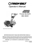
Rear-tine Tiller Models
644HmBronco
645AmBronco
TM
TM
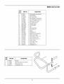
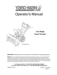
Model 644H Shown (bumper syles vary)
IMPORTANT:READ
SAFETY
RULES AND INSTRUCTIONS
CAREFULLY
Warning: This unit is equipped with an internal combustion engine and should not be used on or near any unimproved forest-covered, brushcovered or grass-covered land unless the engine's exhaust system is equipped with a spark arrester meeting applicable local or state laws (if any).
If a spark arrester is used, it should be maintained in effective working order by the operator. In the State of California the above is required by law
(Section 4442 of the California Public Resources Code). Other states may have similar laws. Federal laws apply on federal lands. A spark arrester
for the muffler is available by contacting the service department at Troy-Bilt LLC, P.O. Box 361131 Cleveland, Ohio 44136-0019.
TROY-BILT
PRINTED
IN USA
LLC, P.O. BOX 361131, CLEVELAND,
OH 44136-0019
FROM NO. 769-00585B
(11/2003)
TABLEOFCONTENTS
Content
Customer Support 2
Safety
3
Assembly
Features and Controls
Page
6
10
Operation 13
Content
Maintenance 19
Off-season Storage
Troubleshooting
Page
24
25
Warranty
Back Cover
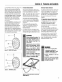
FINDINGMODELNUMBER
This Operator's Manual is an important part of your new lawn tractor. It will help you assemble, prepare and maintain the
unit for best performance. Please read and understand what it says.
Before you start assembling your new equipment, please locate the model plate on the equipment and
copy the information from it in the space provided below. A sample model plate is also given below. You can
locate the model plate by looking at the rear of the tine shield. This information will be necessary to use the
manufacturer's web site and/or help from the Customer Support Department or an authorized service dealer.
Copy the model number here:
Copy the serial number here:
www.troybilt:com
CLEVELAND,
01144136
330-558-7220
1-800-520"5520
CUSTOMER
SUPPORT
Please do NOTreturnthe unit to the retailer withoutfirst contactingCustomerSupport.
If you have difficultyassembling this product or have any questions regarding the controls, operation or maintenance of
this unit, you can seek help from the experts. Choose from the options below:
Visit troy-bilt.com for many useful suggestions. Click on Customer Support button and you
will get the four options reproduced here. Click on the appropriate button and help is
immediately available.
_S
The answer
you are
I lOOKingfor could be just
a mouse click away!
_
....,,_y.... _ ,,.........,_0._.........
The answer you are
looking for could bejust
a mouse click away!
I
The engine manufacturer is responsible for all engine-related issues with regard to
performance, power-rating, specifications, warranty and service. Please refer to the engine
manufacturer's Owner's/Operator's Manual, packed separately with your unit, for more
information.
n
Safety
SPARK ARRESTERWARNING TO RESIDENTSOF CALIFORNIAAND SEVERALOTHERSTATES
Under California law, and under the laws of several other states, you are not permitted to operatean
internal combustion engine using hydrocarbon fuels on any forest, brush, hay, grain, or grass
covered land; or land covered by any flammable agricultural crop without an engine spark arrester in
continuous effective working order.
The engine on the unit is an internal combustion engine which burns gasoline, a hydrocarbon fuel, and must be equipped with a
spark arrester muffler in continuous effective working order. The spark attester must be attached to the engine exhaust system in
such a manner that flames or heatfrom the system will not ignite flammable material. Failureof the owner/operator of the unit to
comply with this regulation is a misdemeanor under California law (and other states) and may also be a violation of other state
and/or federal regulations, laws, ordinances or codes. Contact your local fire marshal or forest service for specific information
about which regulations apply in your area.
Training
1. Carefully read this
Owner's Manual, the
separate Engine Owner's
Manual, and any other literature you may
receive. Be thoroughly familiar with the
controls and the proper use of the tiller
and its engine. Know how to stop the unit
and disengagethe controls quickly.
2. Never allow children to operate the
tiller. Never allow adults to operatethe
tiller without proper instruction.
3. Keepthe area of operation clear of all
persons, particularly children and pets.
4. Keep in mind that the operator or user
is responsible for accidents or hazards
occurring to other people,their property,
and themselves.
Preparation
1. Thoroughly inspect the area where the
tiller is to be used and remove all foreign
objects.
2. Be sure all tiller controls are released
and both wheels are in the Wheel Drive
position before starting the engine.
3. Do not operatethe tiller without
wearing adequate outer garments. Avoid
loose garments or jewelry that could get
caught in moving parts.
4. Do not operatethe tiller when barefoot
or wearing sandals, sneakers, or light
footwear. Wear protective footwear that
will improve footing on slippery surfaces.
5. Do not till near underground electric
cables, telephone lines, pipes or hoses. If
in doubt, contact your telephone or utility
company.
6. Warning: Handlefuel with care; it is
highly flammable and its vapors are
explosive. Be sure to take the following
precautions:
a. Store fuel in containers specifically
designedfor this purpose.
b. The gas cap shall never be removed
or fuel added while the engine is
running. Allow the engine to cool
for several minutes before adding
fuel.
c. Keep matches,cigarettes, cigars,
pipes, open flames, and sparks
away from the fuel tank and fuel
container.
d. Fill fuel tank outdoors with extreme
care. Never fill fuel tank indoors.
Use a funnel or spout to prevent
spillage.
e. Replaceall fuel tank and container
caps securely.
I. If fuel is spilled, do not attempt to
start the engine, but move the
machine away from the area of
spillage and avoid creating any
source of ignition until fuel vapors
havedissipated.
7. Never make adjustments when engine
is running (unless recommended by
manufacturer).
Operation
1. Do not put hands or feet near or under
rotating parts. The tines begin to rotate
once the engine starts and the Forward
Clutch Bail (or ReverseClutch Control) is
engaged.
2. Exerciseextreme caution when on or
crossing gravel drives, walks, or roads.
Stay alert for hidden hazardsor traffic. Do
not carry passengers.
3. After striking a foreign object, stop the
engine, remove the wire from the spark
plug and prevent it from touching the
spark plug, thoroughly inspect the
machine for any damage, and repair the
damage before restarting and operating
the machine.
4. Exercisecaution to avoid slipping or
falling.
5. If the unit should start to vibrate abnormally, stop the engine, disconnect the
spark plug wire and prevent it from
touching the spark plug, and check
immediately for the cause. Vibration is
generally a warning of trouble.
6. Stop the engine, disconnect the spark
plug wire and prevent it from touching
the spark plug whenever you leavethe
operating position, before unclogging the
tines, or when making any repairs, adjustments or inspections.
Section1: Safety
7. Take all possible precautions when
leavingthe machine unattended. Stop the
engine. Disconnect spark plug wire and
move it away from the spark plug. Be
sure both wheels are in the Wheel Drive
position.
8. Before cleaning, repairing, or inspecting, stop the engine and make certain all
moving parts havestopped. Disconnect
the spark plug wire and prevent it from
touching the spark plug to prevent accidental starting.
9. The flap on the tine hood must be
down when operating the tiller.
10. Never usethe tiller unless proper
guards, plates, or other safety protective
devices are in place.
11. Do not run engine in an enclosed
area. Engine exhaust contains carbon
monoxide gas, a deadly poison that is
odorless, colorless, and tasteless.
12. Keep children and pets away.
13. Never operatethe tiller under
engine powerif the wheels are in the
Freewheel position. In the Freewheel
position,the wheels will not hold the
tiller backand the revolvingtines could
propelthe tiller rapidly, possibly
causing loss of control.Always engage
the wheels with the wheel drive pins in
the Wheel Drive position before starting
the engine or engaging the tines/wheels
with the Forward Clutch Bail or the
ReverseClutch Control.
14. Be aware that the tiller may unexpectedly bounce upward or jump backward
and be propelled toward you if the tines
should strike extremely hard packed soil,
frozen ground, or buried obstacles like
large stones, roots, or stumps. If in doubt
about the tilling conditions, always use
the following operating precautionsto
assist you in maintaining control of the
tiller:
a. Walk behindand to one side of the
tiller, using one handon the handlebars. Relax your arm, but use a
secure hand grip.
b. Use a deep depthregulator
setting.
c. Useslower engine speeds.
d. Clear the tilling area of all large
stones, rootsand other debris.
e. Avoid using downwardpressure
on handlebars.If need be, use
slight upward pressureto keep the
tines from diggingtoo deeply.
f. Beforecontactinghard packedsoil
at the end of a row, reduceengine
speed and lilt handlebarsto raise
tines out of the soil.
g. In an emergency, stoptines and
wheels by releasing whichever
clutchcontrolis engaged. Do not
attemptto restrain the tiller.
15. Do not overload the tiller's capacity
by attempting to till too deeply at too fast
a rate.
16. Never operate the tiller at high
transport speeds on slippery surfaces.
Look behind and use great care when
backing up.
17. Do not operatethe tiller on a slope
that is too steep for safety. When on
slopes, slow down and make sure you
have good footing. Never permit the tiller
to freewheel down slopes.
18. Never allow bystanders near the unit.
19. Only use attachments and accessories that are approved by the manufacturer of the tiller.
20. Use tiller attachments and accessories when recommended.
21. Never operate the tiller without good
visibility or light.
22. Never operate the tiller if you are
tired, or under the influence of alcohol,
drugs or medication.
23. Operators shall not tamper with the
engine-governor settings on the machine;
the governor controls the maximum safe
operating speed to protect the engine and
all moving parts from damage caused by
overspeed. Authorized service shall be
sought if a problem exists.
24. Do not touch engine parts which may
be hot from operation. Let parts cool
down sufficiently.
25. Pleaseremember: You can always
stop the tines and wheels by releasingthe
Forward Clutch control or the Reverse
Clutch control (whichever control you
have engaged), or by moving the throttle
control lever on the engine to "OFF"or
"STOP".
26. To load or unload the tiller, seethe
instructions in Section 4 of this Manual.
27. Use extreme caution when reversing
or pulling the machine towards you.
28. Start the engine carefully according to
instructions and with feet well away from
the tines.
29. Never pick up or carry a machine
while the engine is running.
Maintenance and Storage
1. Keepthe tiller, attachments and accessories in safe working condition.
2. Checkall nuts, bolts, and screws at
frequent intervals for proper tightness to
be sure the equipment is in safe working
condition.
3. Neverstore the tiller with fuel in the
fuel tank inside a building where ignition
sources are present such as hot water
and space heaters,furnaces, clothes
dryers, stoves, electric motors, etc.).
Allow engine to cool before storing in any
enclosure.
4. To reduce the chancesof a fire hazard,
keepthe engine free of grass, leaves,or
excessive grease.
5. Store gasoline in a cool, well-ventilated
area, safely away from any spark- or
flame-producing equipment. Store
gasoline in an approved container, safely
away from the reachof children.
6. Refer to the Maintenancesections of
this Manual and the separate Engine
Owner's Manualfor instructions if the
tiller is to be stored for an extended
period.
7. Never perform maintenancewhile the
engine is running or the spark plug wire
is connected, except when specifically
instructed to do so.
8. If the fuel tank hasto be drained, do
this outdoors.
Section1: Safety
Decals
Keepthe decals clean and legible at all
times. Contact your local service dealer
or the factory for replacements if any
decals are damagedor missing.
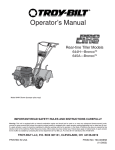
For your safety and the safety of others,
various safety and operational decals are
located on your unit (see Figure 1 below).
Refer to the separate parts catalog for
decal locations, part numbers and
ordering instructions.
ForwardClutchControl
OperatingInstruction
Reverse ClutchControl
OperatingInstruction
StartingStabilization
Message on engine
Warning Messages
ontine hood
HotSurfaces
Warning on belt cover
Figure 1: Location of Safety and Operating Decals (Model 644H shown).
Operating Symbols
Various symbols (shown here, with word
descriptions) are used on the tiller and engine
(your unit may not haveall of the symbols).
i÷i I÷1 R
CHOKE
ON
SLOW
STOP
REVERSE
ROTATING
TINES
BAIL
€,E-->
FAST
CHOKE
OFF
<--lZ,
TILLER DIRECTION
_-_
0 _
ENGAGED
LEVERDIRECTION
TO AVOID SERIOUS INJURY:
READTHE OWNER'S MANUAL.
KNOWLOCATIONSANDFUNCTIONSOF ALL CONTROLS.
KEEPALLSAFETYDEVICESAND SHIELDSIN PLACEANDWORKING.
NEVERALLOWCHILDRENOR UNINSTRUCTEDADULTSTO OPERATETILLER.
SHUT OFFENGINEAND DISCONNECTSPARKPLUGWIRE BEFOREMANUALLYUNCLOGGINGTINESOR MAKINGREPAIRS.
• KEEPBYSTANDERSAWAYFROM MACHINE.
• KEEPAWAYFROM ROTATINGPARTS.
• USEEXTREMECAUTIONWHENREVERSINGOR PULLINGTHE MACHINETOWARDSYOU.
•
•
•
•
•
BAIL
DISENGAGED
n
Assembly
WARNING
NOTE:Be careful not to severely bend any
of the control cables on the unit.
To prevent personal injury or
property damage, do not start
the engine until all assembly
steps are complete and you
have read and understand the
3. Removeall unassembled parts and
the separate hardware bag from the
carton. Checkthat you havethe items
listed below (contact your local dealer or
the factory if any items are missing or
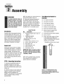
damaged). NOTE: Use the screw length
template (Fig. 2-1) to identify screws.
safety and operating instructions in this manual.
LooseParts List
Introduction
Carefullyfollow these assembly steps to
correctly prepare your tiller for use. It is
recommendedthat you read this Section
in its entirety before beginning assembly.
NOTE: Enginesyles vary by model. The
engine on your tiller may appear differently than those shown in illustrations
and Figures throughout this manual.
Inspectunit
Inspect the unit and carton for damage
immediately after delivery. Contact the
carrier (trucking company) if you find or
suspect damage. Inform them of the
damageand request instructions for filing
a claim. To protect your rights, put your
claim in writing and mail a copy to the
carrier within 15 days after the unit has
been delivered.
Qty.
Tools/MaterialsNeededfor
Assembly
(2)
1/2" open-end wrench*
(1)
3/8" open-end wrench*
(2)
9/16" open-end wrench*
(1)
Large adjustable wrench
(1)
Scissors (to trim plastic ties)
(1)
Ruler (for belt tension check)
(1)
Block of wood (to support tiller
when removing wheels)
Description
1
HandlebarSupport (seeA, Fig. 2-2,
page 7)
1 HandlebarAssembly
(see K, Fig. 2-2)
Thefo//owing itemsare in the
hardware bag:
4 Hex hd. screw, 5/16-18 x 1-1/2"
2 Hex hd. screw, 3/8-16 x 3/4"
2 Flat washer, 3/8"
4 Split Iockwasher, 5/16"
4 Hex nut, 5/16"-18
2 Hex Iocknut, 3/8"-16
(1) Automotive-type air pressure gauge
(1)
Cleanoil funnel
(1)
Clean, high-quality engine oil. Refer
to the Engine Owner Manual for
engine oil specifications and quantity
required. Do not overfill.
* Adjustable wrenches may be used.
IMPORTANT:Motor oil mustbe addedto
the engine crankcasebeforethe engine
is started. Followthe instructionsin this
"Assembly" section.
NOTE:LEFTand RIGHTsides of the tiller
are as viewed from the operator's
position behind the handlebars.
STEP 1: Unpacking Instructions
1. Removeany cardboard inserts and
packaging material from the carton.
Removeany staples from the bottom of
the carton and then lift the carton up and
off the unit.
2. The tiller is heavyand you should not
attempt to remove it from the shipping
platform until the handlebarsare
installed. The procedure for removing the
tiller is explained in Step 3 of these
assembly steps.
Figure2-1: Toidentifylength ofscrew,
placescrewontemplateasshownand
measuredistancebetweenbottomofscrew
headandtip ofscrew.
Section2: Assembly
STEP 2: Attach Handlebar
1. Attach the two legs of the handlebar
support (A, Fig. 2-2) loosely to the inner
sides of the tiller frame using two 3/8"-16
x 3/4" hex hd. screws (B), two 3/8" flat
washers (C) and 3/8"-16 hex Iocknuts (D).
2. Using using two 5/16"-18 x 1-1/2" hex
hd. screws (G), 5/16" split Iockwashers
(H) and 5/16"-18 hex nuts (I), loosely
attach the the handlebar support (A) using
the upper holes.
3. There are three height adjustment holes
in the two handlebarsupport brackets. E
& F, Fig. 2-2). Use a setting that will
position the handlebarsat approximately
waist level when the tines are 3"-4" into
the soil. Loosely attach the handlebar
support brackets to the outside of the
handlebar assembly (K) using two 5/16"18 x 1-1/2" screws (G), 5/16" split lockwashers (H) and 5/16"-18 hex nuts (I).
NOTE:If a support bracket will not move,
loosen attaching screw (J) and nut.
IMPORTANT:The support brackets must
be assembledto the outsideof the
handlebar assembly.
4. Tighten all handlebar mounting
hardware securely.
STEP 3: Move Tiller Off Shipping
Platform
To move the tiller without the engine
running, put the wheels in their
FREEWHEELposition, as described below.
Fig. 2-2: Attach handlebar.
1. Use a sturdy block to raise one wheel
off the ground.
2. Removethe hairpin cotter (L, Fig. 2-3)
and wheel drive pin (M). Slide the wheel
inward on the wheel shaft (N). Reinstall
the wheel drive pin and hairpin cotter
through the wheel shaft only (not through
the wheel hub). Repeat with the other
wheel.
3. Using the handlebar as a lever, roll the
tiller to a flat area.
IMPORTANT:Before starting the engine,
the wheels must be placed in their WHEEL
DRIVEposition (pins through wheel hubs
and wheel shaft). This procedure is
described in "Wheel Drive Pins" in
Fig. 2-3: Wheel in FREEWHEELING
position (wheel drive pin throughwheel
shaft only).
Section2: Assembly
STEP4: Install Forward Clutch Cable
1. Carefully unwrap the forward clutch
cable (the cable without a knob attached to
it) from its shipping position and slide the
thin cable wire (T, Fig. 2-4) into the slot in
the cable bracket. Pushthe cableconnector
(U, Fig. 2-4) up through the hole in the
bracket until the groove in the connector
snaps into place on the bracket.
2. Threadthe #10-24 hex nut (Z) halfway
onto the screw (V) which runs through the
spring (W, Fig.2-5).
3. Thread screw (V) into cable adjuster (X).
4. Lift and hold the Forward Clutch bail
against the handlebar. See Fig. 2-7.
5. Measure the length of the cable spring
betweenthe ends of the coils (Fig. 2-7).
The length should be approximately 1-7/8".
If the length is correct, turn the #10-24 hex
nut (Z) down tightly against the cable
adjuster (X) while holding the adjuster in
place. See Figure 2-7. If the length is
incorrect, you must make an adjustment to
the cable tension as described in
Fig. 2-4: Installing forwardclutchcable bracket and cable.
Fig. 2-5: Assemble
springand adjuster.
"Checking and Adjusting Forward Drive
BeltTension" in Section 5. When the
spring length is correct, tighten the hex nut
(Z) against the cable adjuster (X).
STEP5: Install ReverseClutch
Cable
Fig. 2-6: Install forwardclutch cable.
1. Unwrap the reverse clutch cable (the
cable with a knob and a large hex nut
attached to it) from around its shipping
position and route the cable (CC, Fig. 2-8
and Fig. 2-9) up to the cable bracket (BB,
Fig. 2-8). Be sure that the cable goes
beneaththe Forward Clutch Bail as it is
routed up to the cable bracket.
2. Insert the cable up through the slot in
the cable bracket and position the threaded
assembly as shown in Fig. 2-8. Make sure
that the flat side of the threaded assembly
is aligned with the flat side of the mounting
hole. Slide the large hex nut (DD) up the
cable and tighten it securely.
Fig. 2-7: Measure cable spring.
Section2: Assembly
3. Use a cable tie (EE,Fig. 2-9) to fasten
the reverse clutch cableto the left side
handlebar.
STEP6: CheckLevelof
TransmissionGearOil
4. Test the function of the reverse clutch
cable by pulling the knob out and
releasingit. The knob should return to its
neutral position (resting against bracket)
when it is released. If it doesn't, contact
your local dealer or the factory for
technical assistance.
The transmission was filled with gear oil
at the factory. However, you should check
the gear oil levelto make certain it is
correct.
IMPORTANT:Do not operate the tiller if
the gear oil level is low. Doing so will
result in severe damageto the transmissign components.
1. Put the tiller on levelground. Pull the
Depth Regulator Lever (FF, Fig. 2-10)
back and then adjust it up or down to the
notch that makesthe tiller level.
BB
Fig. 2-10: Adjust DepthRegulator Lever.
2. Removethe oil fill plug (GG,Fig. 2-11)
from the transmission housing and look
into the oil fill hole. You will see the main
drive shaft on one side of the hole.
DD
3. The gear oil level is correct if the gear
oil is approximately halfway up the side of
the drive shaft.
Flat Side
Fig. 2-8: Install reverse cable mounting
bracketand the reverse clutchcable.
4. If the gear oil level is low, add gear oil
by referring to "A. To Checkthe Transmission Gear Oil Level" in Section 5.
Fig. 2-11: Remove gear oil fill plug.
STEP 7: Add Motor Oil to Engine
CC
The tiller is shipped withoutoil in the
engine.
IMPORTANT:Do not start the engine
without first adding motor oil. Severe
engine damagewill result if the engine is
run without oil.
1. Refer to the Engine Owner's Manual
(supplied with tiller) for engine oil specifications and capacities.
2. With the tiller on level ground, pull the
Depth Regulator Lever (FF, Fig. 2-10)
back and then slide it up or down as
necessaryuntil the engine is level.
3. Add motor oil as described in the
EngineOwner's Manual.
Fig. 2-9: Route reverse clutchcable (CC) as
shown. Attach to handlebar with cable tie
(EE).
4. Move the Depth Regulator Lever all the
way down until the highest notch is
engaged. This places the tines in the
"travel" position.
STEP 8: Check Hardware for
Tightness
Checkall nuts and screws for tightness.
STEP9: CheckAir Pressurein
Tires)
Use a tire pressure gauge to check the air
pressure in both tires. Deflateor inflate
both tires equally to 15-to-20 PSI
(pounds per square inch). Be sure that
both tires are inflated equally or the unit
will pull to one side.
IMPORTANT:This completes the
assembly steps. Beforeoperating your
tiller, make sure you read the following
Sections in this Manual, as well as the
separate Engine Owner's Manual:
• Section 1: "Safety"
• Section 3: "Featuresand Controls"
• Section 4: "Operation"
n
Featuresand Controls
WARNING
Before
operating
your
machine, carefully read and
understand all safety, controls
and operating instructions in
this Manual, the separate
Engine Owner's Manual, and
on the decals on the machine.
Failure
to
instructions
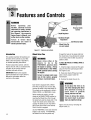
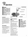
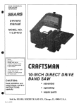
Forward
Clutch Bail
ReverseClutch
Control
Regulator
Handlebar Height
Adjustment
follow
these
can result in
Anti-ReverseStake
serious personal injury.
Drive Pin
(on eachwheel)
Figure 3-1: Featuresand controls.
Introduction
This section describesthe locations and
functions of the controls on your tiller.
Refer to the next section ("Operation")
for detailed operating instructions.
Practice using these controls, with the
engine shut off, until you understand the
operation of the controls and feel
confident with each of them.
IMPORTANT:Refer to the separate
engine manufacturer's Engine Owner's
Manual for informationabout the
controls on the engine.
Wheel Drive Pins
WARNING
Never allow
wheels
to
either of the
be
in the
FREEWHEEL position when
the engine is running. Always
put both wheels in the WHEEL
DRIVE position before starting
the engine.
Failure to comply could cause
loss of tiller control, property
damage, or personal injury.
through the holes in the wheel shaft (not
the wheel hubs), thus allowing the wheels
to turn freely when the tiller is pushed or
pulled by hand.
To Placethe Wheels in WHEELDRIVEor
FREEWHEEL:
1. Stop the engine, disconnect the spark
plug wire from the spark plug and allow
the engine to cool.
2. Raiseone wheel off the ground and
place a sturdy support under the
transmission.
3. Removethe wheel drive pin (A,
WARNING
Eachwheel is equipped with a Wheel
Drive Pin (A, Figures3-2 and 3-3) that
secures the wheel to the wheel shaft (B).
The wheels can be positioned in either a
WHEELDRIVEor a FREEWHEELmode.
Before starting the engine, put both
wheels in the WHEELDRIVEposition by
inserting the Wheel Drive Pins through
the wheel hubs and the wheel shaft. This
"locks" the wheels to the wheel shaft,
causing the wheels to turn when either
the Forward Clutch Bail or the Reverse
Clutch Control is engaged.
10
Use the FREEWHEELmode only when the
engine is not running. In FREEWHEEL,
the Wheel Drive Pins are placed only
Do not place the tiller on its
side when changing the wheel
drive positions as doing so
could result in gasoline
leaking from the fuel tank.
Failure to follow this instruction could result in personal
injury or property damage.
Figures 3-2 and 3-3) by removing the
hairpin cotter (C).
Section3: FeaturesandControls
4. FORWHEELDRIVEmode (Figure3-2):
Slide the wheel outward and align the
holes in the wheel hub (D, Figure3-2))
and the wheel shaft (B). Insert the wheel
drive pin (A) through the wheel hub and
the wheel shaft. Securethe wheel drive
pin with the hairpin cotter (C) by pushing
the hairpin cotter in as far as it will go.
Repeatfor the other wheel and then
remove the support from beneaththe
transmission.
5. FORFREEWHEELmode (Figure 3-3):
Slide the wheel inward and insert the
wheel drive pin (A, Figure 3-3) only
through the hole in the wheel shaft (B).
Secure the wheel drive pin with the
hairpin cotter (C) by pushing the hairpin
cotter in as far as it will go. Repeatfor the
other wheel and then remove the support
from beneaththe transmission.
Forward Clutch Bail
ReverseClutchControl
The Forward Clutch Bail (E, Figure3-4)
controls the engagement of forward drive
to the wheels and power to the tines.
The ReverseClutch Control (F, Figure3-4)
controls the engagement of reverse drive
to the wheels and tines. This powered
reversing feature is used for maneuvering
the tiller only - never engagethe tines in
the ground while going in the reverse
direction.
NOTE: The wheels will rotate in a forward
direction; the tines will rotate counterclockwise (backwardtoward the operator).
To Operatethe Forward ClutchBail:
1. Put the wheels in the WHEEL DRIVE
position (see the following "WARNING"
statement).
2. Lift and hold the bail against the
handlebar. The wheels and tines will
rotate- and the tiller will move in a
forward direction.
3. Releasethe bail to disengage(stop)
the wheels and tines. Forwardtiller motion
will stop (the engine will continue to run).
WARNING
I
Before starting the engine, be
sure that both wheels are in
To Operatethe Reverse ClutchControl:
1. Operateonly when the wheels are in
the WHEEL DRIVEposition (seethe
"WARNING" statement at the left).
2. Stop all tiller motion by releasingthe
Forward Clutch Bail.
3. Lift up the handlebar until the tines
clear the ground, look behind you to avoid
any obstacles, and then pull the reverse
clutch control knob toward you. The
wheels will rotate in a reverse direction.
4. Releasethe reverse clutch control
knob to disengage (stop) the wheels and
tines. All reverse motion will stop (the
engine will continue to run).
the WHEEL DRIVE position.
See "Wheel Drive Pins" for
instructions.
Engaging the Forward Clutch
Bail or the Reverse Clutch
Control when the wheels are
not in the WHEEL DRIVE
Figure3-2: WHEELDRIVEposition.
I
position could allow the tines
to rapidly propel the tiller
forward or backward.
Failure to comply could cause
loss of tiller control, property
damage, or personal injury.
WARNING
• Use extreme caution when
reversing or pulling the
machine towards you. Look
behind to avoid obstacles.
• Never attempt
reverse.
to till
in
Failure to follow this warning
could result in personal injury
or property damage.
D
B
Figure3-3: FREEWHEEL
position.
Figure34: FonvardClutchBail (E)andReverse
ClutchControl(F).
11
Section3: FeaturesandControls
DepthRegulatorLever
HandlebarHeightAdjustment
Anti-ReverseStake
This lever (G, Figure3-5) controls the
tilling depth of the tines. Pull the lever
straight back and slide it up or down to
engage the notched height settings.
The handlebar height is adjustable to
three different settings (see Figure 3-6).
As a general rule, adjust the handlebars
so they are at waist level when the tines
are 3"-4" into the soil.
This stake is located at the rear of the
The highest notch (lever all the way
down) raises the tines approximately 11/2" off the ground. This "travel" setting
allows the tiller to be moved without the
tines digging into the ground. Also use
this setting when starting the engine.
Move the lever upward to increase the
tilling depth. The lowest notch allows a
tilling depth of approximately 6"-8",
depending on soil conditions.
To Adjustthe Handlebars:
1. Stop the engine, disconnect the spark
plug wire from the spark plug and allow
the engine to cool.
2. Removethe screws, Iockwashers and
nuts, reposition the handlebars, and
reinstall the hardware.
For best results, begin tilling at the
deepest depth possible without causing
the tiller to bog down. Increasethe tilling
depth from one pass over the soil to the
next.
Travel
Position
transmission, under the tine hood (see H,
Figure 3-7). Its purpose is to automatically help prevent the counter-rotating
tines from letting the tiller back up in the
direction of the operator if the tiller
wheels had been inadvertently left in the
FREEWHEELposition. In this situation,
the Anti-Reverse Stake will be forced
down into the ground, lifting the tines
upward out of the soil and helping
prevent backward motion of the tiller.
TheAnti-ReverseStake requires no adjustment, but should be inspected before
eachtiller useto verify that it swivels
freely. Remove any clogged materials
(dirt, roots, rocks, etc.) that prevent the
Anti-Reverse Stake from swinging freely.
L_
jG
Shallow
Deep
_
Settings
Figure3-6: Handlebar height adjustment.
Figure3-5: Depth regulator lever.
WARNING
H
• Place the Depth Regulator
Lever
in the
"travel"
position before starting the
engine.
This position
prevents the tines from
touching the ground until you
are ready to begin tilling.
Failure to follow this warning
could result in personal injury
or property damage.
Figure 3-7: Anti-ReverseStake.
ENGINECONTROLS
Refer to the engine manufacturer's Engine
Owner's Manual (included in the tiller literature package) to identify the controls
on your engine.
IMPORTANT:The control for stopping the
engine is located on the engine.
12
.........................
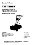
Operation
Reverse Clutch Control
(knobon backofbracket)
WARNING
Before
operating
your
machine, carefully read and
understand all safety (Section
1), controls (Section 3) and
operating instructions (Section
4) in this Manual,
in the
separate
Engine Owner's
Manual, and on the decals on
the machine.
__---_FonNard
DepthRegulatorLever
Failure to follow these instructions can result in serious
Ii-Reverse Stake
personal injury.
Recoil
INTRODUCTION
Readthis Section of the manual thoroughly beforeyou start the engine. Then,
take the time to familiarize yourself with
the basic operation of the tiller before
using it in the garden. Find an open, level
area and practice using the tiller controls
without the tines engaging the soil (put
tines in "travel" setting). Only after
you've become completely familiar with
the tiller should you begin using it in the
garden.
INITIAL OPERATION
Perform the following maintenanceduring
the first hours of new operation (see
"Maintenance" section in this manual and
in the Engine Owner's Manual).
1. Changeengine oil after first 2 hours of
new engine operation.
Wheel Drive Pin
(on eachwheel)
Figure4-1
STARTINGAND STOPPINGTHE
ENGINE
Pre-StartChecklist
Make the following checks and perform
the following services before starting the
engine.
1. Readthe "Safety" and "Controls"
sections in this manual. Readthe
separate Engine Owner's Manual
provided by the engine manufacturer.
2. Checkthat the wheels are in the
WHEELDRIVEposition (wheel pins must
be through the wheel hubs and the wheel
shaft holes).
DANGER
GASOLINE
IS
HIGHLY
FLAMMABLE
AND
ITS
VAPORSARE EXPLOSIVE.
Followgasolinesafety rules in
this manual (see Section 1)
and in the separate Engine
Owner'sManual.
Failure to follow gasoline
safety instructionscan result
in serious personal injury
and property damage.
3. Check unit for loose or missing
hardware. Service as required.
4. Checkengine oil level. See Engine
Owner's Manual.
2. Checkfor loose or missing hardware
on unit. Tighten or replace as needed.
3. Checktension on forward drive belt
5. Checkthat all safety guards and
covers are in place.
after first 2 hours of operation.
6. Checkair cleaner and engine cooling
system. See Engine Owner's Manual.
4. Checktransmission gear oil level after
first 2 hours of operation.
Clutch Bail
7. Attach spark plug wire to spark plug.
8. Fillthe fuel tank with gasoline
according to the directions in the
separate Engine Owner's Manual. Follow
all instructions and safety rules carefully.
13
Section4: Operation
Starting the Engine
in the separate Engine Owner's Manual.
The following steps describe how to start
and stop the engine. Do not attemptto
engagetines or wheels until you have
read all the operatinginstructionsin this
Section. Alsoreview the salety rules in
Section1: "Safety" and the tiller and
engine controlsinlormation in Section
3: "Features and Controls."
6. Put ignition switch and/or throttle
control lever on engine in "ON," "RUN,"
"FAST"or "START" position as instructed
in the separate Engine Owner's Manual.
CAUTION
To help prevent serious
personal injury or damage to
equipment:
7. Choke or prime engine as instructed in
the separate Engine Owner's Manual.
8. Place one hand on the fuel tank to
stabilize the unit when you pull the starter
handle. Usethe recoil starter rope to start
the engine as instructed in the separate
Engine Owner's Manual. When engine
starts, gradually move choke lever (on
engines so equipped) to "NO CHOKE,"
"CHOKEOFF"or "RUN" position.
• Before starting engine, put
both wheels in the WHEEL
WARNING
DRIVE position. Never have
the
wheels
in
the
FREEWHEEL position when
the engine is running. When
the
wheels
are
in
FREEWHEEL, they do not
hold back the tiller and the
Hot surfaces can cause severe
burns. Do not touch muffler or
adjacent areas.
9. Usethe "FAST"throttle speed setting
when tilling.
• Before starting engine, put
Forward Clutch Bail (all
Models) and Reverse Clutch
Control in neutral (disengaged) positionsby releasing
levers.
• Avoid engine muffler and
nearby areas. Temperatures
in these areas may exceed
150OF.
1. Completethe "Pre-Start Checklist" on
the previous page.
2. Put the wheels in the WHEELDRIVE
position (see "Wheel Drive Pins" in
Section 3).
3. Put the Depth Regulator Lever in the
"travel" position (lever all the way down)
so that the tines are clear of the ground.
4. Releaseall controls on the tiller.
5. If engine is equipped with a fuel valve,
1t'urn4valve to open position as instructed
up).
1. Follow the "Pre-Start Checklist" on the
previous page. Be sure that the wheels
are in the WHEELDRIVEposition.
2. Put the Depth Regulator Lever in the
"travel" position (lever all the way down)
so that the tines are clear of the ground.
Use this position when practicing with
your tiller or when moving to or from the
garden. When you are readyto begin
tilling, you must move the Depth
Regulator Lever to the desired depth
setting (see "Tilling Tips & Techniques").
Checkthat the Anti-Reverse Stake swivels
freely back and forth. Removeany clogged
material on or around the stake.
WARNING
tines could propel the tiller
rapidly backward.
• Never run engine indoors or
in enclosed, poorly ventilated areas. Engine exhaust
contains carbon monoxide,
an odorless and deadly gas.
This creates an "uppercut" tine action
which digs deeply, uprooting soil and
weeds. Don't overload the engine, but dig
as deeply as possible on each pass. On
later passes,the wheels may tend to spin
in the soft dirt. Help them along by lifting
up slightly on the handlebar (palm facing
Keep away from rotating
tines. Rotating tines will
cause injury.
Stoppingthe Engineand Tiller
1. To stop the wheels and tines, release
the Forward Clutch Bail or the Reverse
Clutch Control -- whichever control is in
use.
2. To stop the engine, put the throttle
control lever on engine in "OFF"or
"STOP" position.
OPERATINGTHE TILLER
The following pages provide guidelines to
using your tiller effectively and safely in
various gardening applications. Be sure
to read "Tilling Tips & Techniques" in this
Section beforeyou actually put the tines
into the soil.
This is a CRT(counter-rotating tine) tiller.
As the wheels pull forward, the tines
rotate backward.
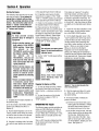
Figure 4-2: Use one hand to guide tiller
when movingforward.
3. Start the engine and allow it to warm
up. When warm, put throttle control in
fast speedsetting.
4. Forforward motion of wheels and
power to the tines:
(a) Pull the Forward Clutch Bail up and
hold it againstthe handlebar. Release
the bail to stop forward motion of
the wheels and power to the tines.
(b) As the tiller moves forward, relaxand
letthe wheels pull the unit along while
the tines dig. Walk behind and a
little to one side of the tiller. Use a
light but secure grip with one hand
on the handlebars, keeping your arm
loose. See Figure 4-2.
Section4: Operation
WARNING
WARNING
Do not push down on the
handlebars to try to make the
tiller till more deeply. This
prevents the wheels from
holding the tiller back and can
allow the tines to rapidly
propel the tiller backward
toward the operator, which
could result in loss of control,
property damage, or personal
injury.
Let the tiller move at its own paceand do
not push down on the handlebarsto try to
dig deeper- this takes weight off the
wheels, cuts traction, and causesthe tines
to try and propel the tiller.
Before tilling, contact your
telephone or utilities company
and inquire if underground
equipment or lines are used in
your area. Their representative will be glad to answer
your questions and tell you if
any of their equipment or lines
are buried underground on
your property.
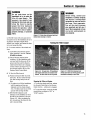
Figure 4-3: Raise tines off groundandlook
behind whenmovingin reverse.
Turning the Tiller Around
5. For reverse motion of the wheels and
tines:
(a) Look behind and exercise caution
when operating in reverse. Do not
till while in reverse.
(b) Stop all forward motion before
reversing. Lift the handlebars with
one hand until the tines are off the
ground and then pull the Reverse
Clutch Control knob out to engage
reverse motion (see Figure4-3). To
stop reverse motion, let go of the
ReverseClutch Control knob.
6. To Turn the Tiller Around:
(a) Practice turning the tiller in a level,
open area. Be very careful to keep
your feet and legs away from the
tines.
(b) To make a turn, lift the handlebars
until the engine and tines are
balancedover the wheels (Figure
4-4). The tines must be out of the
ground while turning the tiller.
(c) With the tiller balanced, push
sideways on the handlebar to move
the tiller in the direction of the turn
(Figure 4-5). After completing the
turn, slowly lower the tines into the
soil to resume tilling.
Figure 4-4: Tobegin turn, lift handlebars
until engine and tines are balanced over
wheels. Besure tines are out of ground.
Figure 4-5: Withtiller balanced over
wheels (and tines out of the ground),push
handlebars sidewaysto turn tiller.
Stoppingthe Tiller and Engine
1. To stop the wheels and tines, release
the Forward Clutch Bail or the Reverse
Clutch Control- whichever is engaged.
2. To stop the engine, move the throttle
control lever on engine to "OFF"or
"STOP" position.
15
Section4: Operation
Tilling Tips& Techniques
Let the tiller dothe work
Avoidtilling soggy,wet soil
* While tilling, relax and let the wheels
pull the tiller along while the tines do
the digging. Walk on the side that is
not yet finished (to avoid making footprints in the freshly tilled soil) and
lightly, but securely grip the handlebar
with just one hand. See Figure 4-2.
Tilling wet soil often results in large,
hard clumps of soil that can interfere
with planting. If time permits, wait a day
or two after heavy rains to allow the soil
to dry before tilling. Test soil by
squeezing it into a ball. If it compresses
too easily, it is too wet to till.
oAvoid the temptation to push down on
the handlebars in an attempt to force
the tiller to dig deeper. Doing so takes
the weight off the powered wheels,
causing them to losetraction. Without
the wheels helping to hold the tiller
back,the tines will attempt to propel
the tiller backward toward the
operator- often causing the tiller to
skip rapidly across the ground.
Tilling depths
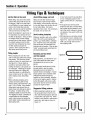
• When preparing the soil, till a fresh
path on each pass rather than overlapping passes. This gives the wheels
maximum traction on undisturbed soil.
See Figure4-6. Dig as deeply as
possible on each pass without overloading the engine. Later passescan
be overlapped. (Watering the garden
area a few days prior to tilling will
make tilling easier, as will letting the
newly worked soil set for a day or two
before making a final, deep tilling
pass.)
• When cultivating (breaking up the
surface soil around plants to help
destroyweeds), adjust the tines to dig
only 1-1/2" to 2" deep. Using shallow
tilling depths helpsprevent injuryto
plantswhose roots often grow closeto
the surface. If needed,lift up on the
handlebarsslightly to prevent the tines
from digging too deeply. Cultivatingon
a regular basis not only eliminates
weeds,it also loosensand aeratesthe
soil for better moistureabsorptionand
faster plantgrowth.
Avoidmakingfootprints
Whenever possible, walk on the untilled
side of the unit to avoid making footprints in your freshly tilled or cultivated
soil. Footprints cause soil compaction
that can hamper root penetrationand
contribute to soil erosion. They can also
"plant" unwanted weed seeds back into
the freshly tilled ground.
Choosingcorrectwheel
and tine speeds
In very hard ground it may take three
or four overlapping passesto thoroughly pulverize the soil. (See Figure
4-8.)
• If the garden size will not permit
lengthwise and then crosswise tilling,
then overlap the first passesby onehalf a tiller width, followed by successive passesat one-quarter width (see
Figure4-8).
• With planning, you can allow enough
room between rows to cultivate (see
Figure4-9). Leaveroom for the hood
width, plus enough extra room for
future plant growth.
Figure4-6
With experience,you will find the "just
right" tilling depth and tilling speed
combination that is best for your
garden.
Set the engine throttle lever at a high
enough speed to give the engine
adequate power and yet allow it to
operate without overloading it. Fastest
engine speeds may be desirable when
making final passesthrough the
seedbed or when cultivating. Selection
of the correct engine speed, in relation
to the tilling depth, will ensure a sufficient power level to do the job without
causing the engine to labor.
Figure 4- 7
Suggestedtilling patterns
• When preparing a seedbed, go over
the same path twice in the first row,
then make individual passes right next
to each other (see Figure4-6). When
finished in one direction, make second
passes at a right angle as shown in
Figure 4-7.
Figure4-8
%
Figure 4-9
16
Section4: Operation
Tilling Tips & Techniques
Clearing the tines
Tilling on slopes
Dry grass, stringy stalks or tough vines
may becometangled in the tines. Follow
these procedures to help avoid tangling
and to clean the tines, if necessary.
If you must garden on a moderate slope,
pleasefollow two very important guidelines:
• To reducetangling, set the depth
regulator to maximum depth.
• While tilling, try swaying the handlebars from side to side (about 6" to 12").
This "fishtailing" action often clears the
tines of debris.
• If tangling occurs, lift the tines out of
the soil and run the tiller in reverse for
a few feet. This may unwind a good
deal of debris.
• It may be necessaryto remove the
debris by hand (a pocket knife will help
you to cut away the material).
WARNING
Before clearing the tines by
hand, stop the engine, allow
all moving parts to stop and
disconnect the spark plug
wire.
Failure to follow this warning
could result in personal
injury.
1. Till only on moderate slopes, never on
steep ground where footing is difficult
(review safety rules in the "Safety"
section of this manual).
B. Tilling acrossslopeswithout
usingterraces:
If previously described tilling methods
aren't practical for you, then you can till
laterally across a slope. However, we
don't really recommend this method as
it can create unsure footing and invites
soil erosion.
2. We recommend tilling up and down
slopes rather than terracing. Tilling
vertically on a slope allows maximum
planting area and also leaves room for
cultivating.
IMPORTANT:When tilling on slopes, be
sure the correct oil level is maintained in
the engine (check every one-half hour of
operation). The inclineof the slope will
cause the oil to slant away from its
normal level and this can starve engine
parts of required lubrication. Keepthe
engine oil level at the full point at all
times!
A. Tilling up and downslopes:
• To keepsoil erosion to a minimum, be
sure to add enough organic matter to
the soil so that it has good moistureholding texture and try to avoid leaving
footprints or wheel marks.
• When tilling vertically, try to make the
first pass uphill as the tiller digs more
deeply going uphill than it does
downhill. In soft soil or weeds, you
may haveto lift handlebars slightly
while going uphill.
17
Section4: Operation
LOADINGAND UNLOADINGTHE
TILLER
WARNING
Loading and unloading the
tiller into or from a vehicle is
potentially hazardous. We
don't recommend doing so
unless absolutely necessary,
as this could result in personal injury or property damage.
However, if you must load or
unload the tiller, follow the
guidelines given next.
• Before loading or unloading, stop the
engine, wait for all parts to stop
moving, disconnect the spark plug wire
and let the engine and muffler cool.
• The tiller is too heavy and bulky to lift
safely by one person. Two or more
people should share the load.
18
• Use sturdy ramps and manually (engine
shut off) roll the tiller into and out of the
vehicle. Two or more people are needed
to do this.
• Ramps must be strong enough to
support the combined weight of the tiller
and any handlers. The ramps should
provide good traction to prevent
slipping; they should haveside rails to
guide the tiller along the ramps; and
they should havea locking device to
secure them to the vehicle.
• The handlers should wear sturdy
footwear that will help to prevent
slipping.
• Position the loading vehicle so that the
ramp angle is as flat as possible (the
less incline to the ramp, the better).
Turn the vehicle's engine off and apply
its parking brake.
° When going up ramps, stand in the
normal operating position and push the
tiller ahead of you. Have a person at
each side to turn the wheels.
When going down ramps, walk
backward with the tiller following you.
Keepalert for any obstacles behind you.
Position a person at eachwheel to
control the speed of the tiller. Never go
down ramps tiller-first, as the tiller could
tip forward.
Use wooden blocks to place on the
downhill side of the wheels if you need
to stop the tiller from rolling down the
ramp. Also, use the blocks to temporarily keepthe tiller in place on the ramps
(if necessary),and to chock the wheels
in placeafter the tiller is in the vehicle.
Whenthe tiller is in the vehicle, prevent
it from rolling by chocking the wheels
with blocks and securely tie the tiller
down.
Maintenance
WARNING
Before
inspecting,
cleaning or servicing the
machine, shut off engine,
wait for all moving parts to
come to a complete stop,
disconnect spark plug wire
and move wire away from
spark plug.
Failure to follow these
instructions can result in
serious personal injury or
property damage.
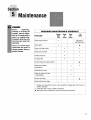
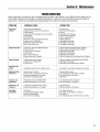
REQUIRED
MAINTENANCE
PROCEDURE
Before
Each
Use
Checkengine oil level
e
Cleanengine
e
SCHEDULE
Every
10
Hours
Every
30
Hours
As
Noted
And every 5
operating hours
A
Check drive belt tension
e
t-
Check nuts and bolts
e
1-
Changeengine oil
e
Lubricate tiller
e
Service engine air cleaner system
A
Checkgear oil level in
transmission
1-
Checktines for wear
Checkair pressure in tires
(if pneumatic)
Service spark plug
A
CheckAnti-Reverse Stake
* Changemore frequently in dusty or dirty conditions, Changeafter first 2 hours of
break-in operation,
1- Checkafter first 2 hours of break-in operation,
A See Engine Owner's Manual for service intervals and instructions.
19
Section5: Maintenance
WARNING
Before inspecting,cleaning or servicing the unit, shut off engine, wait for all
parts to come to a completestop, disconnectspark plug wire and movewire away from spark
plug. Failure to follow these instructions can result in serious personal injury or
propertydamage.
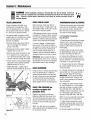
TILLERLUBRICATION
CHECKFOR OIL LEAKS
TRANSMISSIONGEAROIL SERVICE
Proper lubrication of the tiller is an
essential part of maintenance. After
every 10 operating hours, oil or grease
the lubrication points shown in Figures
5-1 and 5-1A and described below.
Before each use, check your tiller for
signs of an oil leak- usually a dirty, oily
accumulation either on the unit or on the
Checkthe transmission gear oil level after
every 30 hours of operation or whenever
you notice any oil leak. Operating the
tiller when the transmission is low on oil
can result in severe damage.
Use a good quality lubricating oil (#30
weight engine oil is suitable) and a quality
general purpose grease (with a metal
lubricant, if available).
,, Removewheels, clean wheel shaft (A,
Fig. 5-1) and apply thin coating of
grease to the shaft.
,, Greaseback, front and sides of depth
regulator lever (B, Fig. 5-1).
,, Removetines, clean tine shafts (C, Fig.
5-1). Inspect for rust, rough spots or
burrs (look around holes). Fileor sand
smooth, coat ends of shaft with grease.
,, Oil the threads on the handlebar height
adjustment screws and the handlebar
attaching screws (D, Fig. 5-1).
• Shifting Mechanism. Lightly oil pivot
pointsfor smooth operation(E,Fig.5-1A).
floor where it has been parked.
A little seepagearound a cover or oil seal
is usually not a cause for alarm. However,
if the oil drips overnight then immediate
attention is neededas ignoring a leak can
result in severe transmission damage.
If a cover is leaking, try tightening any
loose screws. If the screws are tight, a
new gasket or oil seal may be required. If
the leak is from around a shaft and oil
seal, the oil seal probably needsto be
replaced. Seeyour authorized dealer or
contact the factory for service or advice.
IMPORTANT:Never operate the tiller if
the transmission is low on oil. Checkthe
oil level after every 30 hours of operation
and whenever there is any oil leakage.
Figure5-1
Figure5-1A
2O
1. Checkthe gear oil levelwhen the transmission is cool. Gear oil will expand in
warm operating temperatures and this
expansion will provide an incorrect oil
level reading.
2. With the tiller on levelground, adjust
the Depth Regulator Lever up or down to
the notch that makesthe tiller level..
3. Removethe oil fill plug (A, Fig. 5-2)
from the transmission housing and look
into the oil fill hole. You will seethe main
drive shaft on one side of the hole.
CHECKHARDWARE
4. The gear oil level is correct if the gear
oil is approximately half way up the side
of the drive shaft.
Checkfor loose or missing hardware after
every 10 operating hours. Tighten or
replace hardware before using the tiller.
Be sure to check the screws underneath
the tiller hood (lift the hood flap) that
secure the transmission cover and the
depth regulator leverto the transmission.
5. If the gear oil level is low, add gear oil
as described next. If the gear oil level is
okay, securely replacethe oil fill plug.
IMPORTANT:Do not operatethe tiller if
the gear oil level is low. Doing so will
result in severe damageto the transmission components.
CHECKTIREPRESSURE
(on
A
A. To Checkthe Transmission
Gear Oil Level:
machines equipped with
pneumatic tires)
Checkthe air pressure in both tires.
Deflateor inflate both tires evenly from
15-to-20 PSI (pounds per square inch).
Be sure that both tires havethe same air
pressure or the unit will tend to pull to
one side.
NOTE:Your tiller may not be equipped
with pneumatic tires, eliminating the need
for air pressure checks.
6. If adding only a few ounces of gear
oil, useAPI rated GL-4 or GL-5 transmission gear oil having a viscosity of SAE
140, SAE85W-140 or SAE 80W-90. If
refilling an empty transmission, use only
GL-4 transmission gear oil having a
viscosity of SAE 85W-140 or SAE 140.
NOTE:Do not use automatic transmission
fluid or engine oil in the transmission.
7. While checking frequently to avoid
overfilling, slowly add gear oil into the oil
fill hole until it reaches the halfway point
on the drive shaft.
8. Securely replacethe oil fill plug.
Section5: Maintenance
WARNING
Before inspecting, cleaning or servicingthe unit, shut off engine, wait for all
parts to come to a completestop, disconnectspark plug wire and move wire away from spark
plug. Failure to follow these instructions can result in serious personal injury or
propertydamage.
B. To Drain the TransmissionGear Oil:
reducedeffectiveness in general, and
specifically when chopping up and
turning under organic matter.
DANGER
Gasoline is highly flammable
and its vapors explosive. Follow these safety practices to
prevent injury or property
damage from fire or explosion.
,, Allow the engine and
muffler
to cool before
draining the tiller's gasoline
tank.
B. Removingand Installing
Tine Assemblies
1. Use a 9/16" socket, 6" extension, a
ratchet, and a 9/16" box end wrench to
loosen the nut (A, Figure 5-3) and screw
(B) that secure the tine holder to the tine
shaft.
,, Do not allow open flames,
sparks, matches or smoking
in the area.
Figure5-2: Removeoil fi// plug(A)tocheck
gearoil/eve/and toaddgearoil. Remove
fourcoverscrews(B) todraingearoil.
,, Wipe away spills and push
tiller away from spilled fuel.
TINES
,, Use only an approved fuel
container and store it safely
out of the reach of children.
,, Do not store gasoline where
its vapors could reach an
open flame or spark, or
where ignition sources are
present (such as hot water
and space heaters, furnaces,
clothes
dryers,
stoves,
electric motors, etc.)
The transmission gear oil does not need
to be changed unless it has been contaminatedwith dirt, sand or metal particles.
1. Drain gasoline from the fuel tank or
run the engine until the fuel tank is empty.
See "DANGER"statement above.
2. Drain the oil from the engine.
3. Removethe four screws (B, Figure5-2)
and washersfrom the transmission cover
and remove the cover and gasket.
4. Removethe left-side wheel.
5. Tilt the left-side wheel shaft into a
drain pan and allow the gear oil to drain
through the top of the transmission.
6. After draining oil, reinstall the wheel,
install a new gasket (do not reuse old
gasket) and screw on transmission cover.
7. Refill transmission using GL-4 gear oil
(SAE85W-140 or SAE 140).
8. Refill the engine with motor oil and
replenishthe fuel tank with gasoline.
The tines wear with use and they should
be inspected at the beginning of each
tilling season and after every 30 operating
hours. The tines can be replaced individually or as a complete set. Refer to the
Parts List Section of this manual for tine
identification information.
WARNING
This is a CRT (counter-rotating
tine) tiller and its tines must
be mounted in the direction
shown in Figure 5-3.
If
mounted with curves in the
opposite direction, tiller will
dig poorly and be more likely
to run backward.
Failure to comply could result
in personal injury or property
damage.
NOTE:You must first remove the tiller
hood before removing either a single tine
holder or individual tines. Removethe
two screws at the front of the hood and
the two screws at the rear of the hood
and lift off the hood. Be sure to replace
the hood securely after changing a tine or
tine holders.
A. Tine Inspection:
With use, the tines will become shorter,
narrower and pointed. Badly worn tines
will result in a loss of tilling depth and
2. Use a rubber mallet to tap the tine
holder loose. Slide tine assembly off.
3. RepeatSteps 1 and 2 aboveto remove
the other tine assembly.
4. Installing the tine assembly is simply
the reverse of its removal. First be sure
to remove any rust, unevenspots or burrs
from the tine shaft using fine sandpaper.
Then greasethe tine shaft before reinstalling the tine assemblies. Be sure all
the cutting edgesface so they will enter
the soil first when the tiller is moving
forward- this meansthe cutting edge on
the top of each tine faces towardthe
operator position. Tighten hardware.
C. Removingand Installing
IndividualTines
1. Use two 9/16" box end wrenchesto
remove the two screws (C, Figure 5-3)
and nuts (D) that secure the tine to its
tine holder.
NOTE:If the nuts are rusted, apply penetrating oil, then loosen the hardware.
2. When installing individual tines, do so
in the reverse order from which they were
removed. The two sets of inboard tines
are installed so one set faces toward the
transmission and the other faces away
from it. The single outboardtine set
faces toward the transmission housing.
Also be sure the cutting edge at the top
of each fine faces toward the operator
position. (See Figure 5-3.)
21
Section5: Maintenance
WARNING
Before inspecting, cleaning or servicing the unit, shut off engine, wait for all
parts to come to a completestop, disconnectspark plug wire and move wire away from spark
plug. Failure to follow these instructions can result in serious personal injury or
propertydamage.
Clutch Bail all the way up to the bottom of
the upper handlebars,you will need to
loosen the belt tension.
OPERATOR
POSITION
C
Also check the belt for cracks, cuts or
frayed edges and replaceit as soon as
possible.
TINED
A
• Checkbelt tension after the first two
hours of initial operation (new belt).
• Checkbelt tension after every 10
operating hours.
ENGINE
To CheckForwardBelt Tension:
,'_
1. Be sure that the engine is stopped and
the spark plug wire is disconnected and
moved away from the spark plug.
DENOTES CUTTING EDGE _3
OF TINE
|
Figure5-3: Tines,tineholdersandinstallation
hardware.
2. Loosen nut "C" (Figure 5-4) several
turns so it is about halfway up the
threaded adjustment screw.
3. Lift the Forward Clutch Bail up and
hold it to the bottom of the handlebars.
Measure the length of the clutch bail
spring (A, Figure 5-4) with a ruler. If the
belt tension is correct, the length of the
coiled portion of the spring should be
approximately 1-7/8". Nut "C" should
then be snugged down against the top of
the adjuster (B).
4. If the spring is too short, the belt
tension will be too loose. If the spring is
too long, the belt tension will be too tight.
Figure5-4: Liftbail andchecklengthofClutchBailSpringtocheckforcorrectbelttension
(1-7/8").
CHECKINGAND ADJUSTING
FORWARDDRIVE BELTTENSION
Maintaining correct tension on the
forward drive belt is important to good
tilling performance and long belt life. A
loose belt will slip on the engine and
22
transmission pulleys and cause the tines
and wheels to slow down - or stop completely - even though the engine is
running at full speed. A loose belt can
also result in premature belt wear.
If you find you can not bring the Forward
5. To adjust the length of the spring,
releasethe Forward Clutch Bail. Thread
the hex nut (C, Fig. 5-4) halfway up the
adjustment screw. Turn the screw inside
the spring (A, Figure 5-4) counterclockwise (as viewed from the operator's
position) while holding the adjuster (B)
steadyto increase the length of the
spring, or turn clockwise (as viewed from
the operator's position) to decreasethe
length of the spring.
NOTE:If you have difficulty holding the
adjuster steady by hand, use a pliers or
wrench on the adjuster. While you turn
the screw, keepthe Forward Clutch Cable
Section5: Maintenance
WARNING
Before inspecting, cleaning or servicing the unit, shut off engine, wait for all
parts to cometo a complete stop, disconnectspark plug wire and move wire away from spark
plug. Failure to follow these instructions can result in serious personal injury or
propertydamage.
from turning by gripping the upper end of
the threaded adjuster (B) with pliers.
* Checkbelt tension after the first two
hours of break-in operation (new belt).
6. Repeat Step 3 to measure the length
of the clutch bail spring. Oncethe length
is correct, retighten the hex nut against
the top of the adjuster.
- Checkbelt tension after every 10
operating hours.
ForwardBelt Replacement Information
1. Be sure that the engine is stopped and
the spark plug wire is disconnected and
moved away from the spark plug.
If the drive belt needsto be replaced, see
your local authorized dealer or phone the
factory as instructed on Page 2. Refer to
the Parts List in the back of this manual
for correct components Use only OEM
(Original Equipment Manufacturer) freplacement belts. A substitute belt may
not perform satisfactorily. The procedure
requires average mechanicalability and
commonly availabletools.
FORWARDCLUTCH
BAILADJUSTMENT
If the Forward Clutch Bail does not
function properly, first check that the
forward drive belt is adjusted properly
(see "Checking and Adjusting Forward
Drive Belt Tension"). If this fails to
correct the problem, contact the factory
technical service department or your
authorized dealer for service advice.
CHECKINGAND ADJUSTING
REVERSEDRIVE BELTTENSION
Maintaining correct tension on the
reverse drive belt is important to good
performance and long belt life. A loose
belt will slip on the engine and transmission pulleys and cause the tines and
wheels to slow down - or stop completely - even though the engine is
running at full speed. A loose belt can
also result in premature belt wear.
If there is no reverse action when the
ReverseClutch Control knob is pulled
out, then the belt tension is too loose.
When checking belt tension, also check
the belt for cracks, cuts or frayed edges
and replace it as soon as possible.
To CheckReverse Belt Tension:
2. Removethe screw in the plastic belt
cover and slide the cover (which is
attachedto the forward clutch cable) out
of the way.
3. Havean assistant pull the Reverse
Clutch Control knob all the way out and
hold it in that position. Measure the
length of the cable wire between the end
of the threaded cable adjuster (A, Figure
5-5) and the end of the Z-fitting (B) to
which the cable wire is attached.
Figure 5-5: Measure cable wire length to
checkfor correctreverse belt tension.
4. The belt tension is ideal if the cable
wire length measures between 1/8" to
1/4". If the length is less than 1/8" (and if
there is no reverse action when the tiller
is running), then make the following
adjustments. NOTE:If the length is more
than 1/4", no adjustment is needed,as
long as the reverse action functions
properly.
5. Releasethe ReverseClutch Control
knob. Unthreadthe inner jam nut (C,
Figure5-6) one to two turns and pull the
threaded cable adjuster (A, Figure5-6) to
the left until the inner jam nut rests
against the bracket.
6. Prevent the inner jam nut (C) from
turning and tighten the outer jam nut (D)
against the bracket. Prevent the outer
jam nut (D) from turning and tighten the
inner jam nut (C) against the bracket.
7. Measure the gap by repeating Step 3.
Readjust as needed by repeating Steps 5
and 6.
8. Reinstall the belt cover.
Figure 5-6: Move threaded
adjuster (,4) to left to
increase belt tension.
Reverse Belt Replacement Information
If the drive belt needsto be replaced, see
your local authorized dealer or phone the
factory as instructed on Page 2. Refer to
the Parts List in the back of this manual
for correct components Use only OEM
(Original Equipment Manufacturer) freplacement belts. A substitute belt may
not perform satisfactorily. The procedure
requires average mechanicalability and
commonly availabletools.
23
Section5: Maintenance
WARNING
Before inspecting, cleaning or servicing the unit, shut off engine, wait for all
partsto cometo a completestop, disconnectspark plug wire and movewire away from spark
plug. Failure to follow these instructions can result in serious personal injury or
propertydamage.
ENGINEOIL SERVICE
AIR CLEANERSERVICE
Checkthe engine oil level before starting
the engine each day and check it after each
5 hours of continuous operation. Running
the engine when it is low on oil will quickly
ruin the engine.
The engine air cleanerfilters dirt and dust
out of the air before it enters the carbure-
It is recommended that you changethe
motor oil after every 10 hours of operation
and evensooner when operating in
extremely dirty or dusty conditions. Refer
to the separate Engine Owner's Manualfor
detailed service instructions.
A. To Checkthe Engine0il Level:
1. Move the tiller to a level area and shut
off the engine.
2. Levelthe engine by adjusting the Depth
Regulator Lever. The tines must be in
contact with the ground. Move the AntiReverseStake back if necessary.
3. Cleanthe area around the oil dipstick or
oil fill tube to prevent dirt from falling into
the crankcase.
4. On engines with an oil fill tube, remove
the filler cap, add oil (if required) until it
reaches the top of the tube and reinstall the
filler cap.
5. On engines with a dipstick, remove it,
wipe it clean, and reinstall it finger-tight.
Removethe dipstick and check the reading.
Add oil (if required) to bring the levelto the
FULL mark. Do not overfill.
tor. Operating the engine with a dirty,
clogged air filter can cause poor performance and damageto the engine. Never
operatethe engine without the air cleaner
installed. Inspect and service the air
cleaner more often if operating in very
dusty or dirty conditions.
Service the air cleaner as instructed in the
separate Engine Owner's Manual.
SPARKPLUGSERVICE
Inspect and clean or replacethe spark plug
after every 100 operating hours or
annually. Cleanthe plug and set the gap as
described in the separate Engine Owner's
Manual.
In some areas, local law requires using
resistor spark plugs to suppress ignition
signals. If the engine was originally
equipped with a resistor spark plug, use
the same type for replacement.
ENGINECLEANING
Keepthe engine clean to assure smooth
operation and to prevent damagefrom
overheating. Refer to the separate Engine
Owner's Manualfor specific repair and
cleaning instructions. All inspections and
services must be done with the engine shut
off and cool to the touch.
24
WARNING
Operators shall not tamper
with the engine governor
settings on the machine;
the governor controls the
maximum safe operating
speed to protect the
engine and all moving
parts from damage caused
by overspeed. Authorized
service shall be sought if a
problem exists.
OFFSEASONSTORAGE
When the tiller won't be used for
extended periods, prepare it for storage
SPARKARRESTERSCREENSERVICE as follows:
If the engine muffler is equipped with a
spark attester screen, remove and clean it
according to the time intervals and instructions in the separate Engine Owner's
Manual.
B. To Changethe Engine0il:
Changethe engine oil as instructed in the
separate Engine Owner's Manual.
The governor controls the maximum
safe operating speed and protects the
engine and all moving parts from
damagecaused by overspeeding. Do
not tamper with the engine governor
settings.
THROTTLELEVERADJUSTMENT
If the engine does not respond to various
throttle lever settings, refer to the separate
Engine Owner's Manualfor service information or contact your local authorized
engine service dealer.
1. Cleanthe tiller and engine.
2. Do routine tiller lubrication and check
for loose parts and hardware.
3. Protect the engine and perform recommended engine maintenanceby
following the engine storage instructions found in the separate Engine
Owner's Manual. NOTE:Be sure to
protect the fuel lines, carburetor and
fuel tank from gum deposits by
removing fuel or by treating fuel with a
fuel stabilizer (follow engine manufacturer's recommendations).
4. Store unit in a clean, dry area.
CARBURETOR/GOVERNOR
CONTROL 5. Never store the tiller with fuel in the
ADJUSTMENTS
fuel tank in an enclosed area where gas
The carburetor was adjusted at the factory
for best operating speed. Refer to the
separate Engine Owner's Manualfor any
adjustment information or seeyour authorized engine service dealer.
fumes could reach an open flame or
spark, or where ignition sources are
present (space heaters, hot water
heaters,furnaces, etc.).
Section5: Maintenance
TROUBLESHOOTING
Before performing any corrections, refer to the appropriate information in this Manual, or in the Engine Owner's Manual, for the
correct safety precautions and operating or maintenance procedures. Contact your local authorized Engine Service Dealer for
engine service. Contact your local authorized equipment dealer or the factory for all other service problems.
PROBLEM
Enginedoes
notstart.
Enginerunspoorly.
POSSIBLE CAUSE
1. Sparkplug wire disconnected.
2. EngineThrottle ControlLever incorrectlyset.
3. Fueltank empty.
4. Chokecontrol (if so equipped)in incorrect position.
5. Stalegasoline.
6. Dirty air filter(s).
7. Defectiveor incorrectlygappedspark plug.
8. Carburetorout of adjustment.
9. Misadjustedthrottle control cable.
10.Dirt or water in fuel tank.
1.
2.
3.
4.
5.
6.
Engineoverheats.
Defectiveor incorrectlygappedspark plug.
Dirty air filter(s).
Carburetorout of adjustment.
Stalegasoline.
Dirt or water in fuel tank.
Enginecooling systemclogged.
CORRECTION
1. Reconnectwire.
2. Put leverin STARTposition.
3. Addfuel.
4. SeeEngineOwner's Manual.
5. Drain fuel and addfresh fuel.
6. Cleanor replacefilter(s).
7. Inspect sparkplug.
8. SeeEngineServiceDealer.
9. SeeEngineServiceDealer
10. SeeEngineServiceDealer.
1. Inspect sparkplug (seeEngineOwner's Manual).
2. Cleanor replace(seeEngineOwner'sManual).
3. SeeEngineServiceDealer.
4. Replacewith fresh gasoline.
5, SeeEngineServiceDealer.
6. Cleanair coolingsystem (seeEngineOwner'sManual).
1. Enginecooling systemclogged.
2. Carburetorout of adjustment.
3. Oil levelis low.
1. Cleanair coolingarea (seeEngineOwner's Manual).
2. SeeEngineServiceDealer.
3. Checkoil level(seeEngineOwner'sManual).
1. Misadjustedthrottle control or ignition switch.
1. SeeEngineOwner's Manualor EngineServiceDealer.
Wheels andTines
will notturn.
1. Improper use of controls.
2. Worn,broken, or misadjusteddrivebelt(s).
3. Internaltransmission wearor damage.
4. Bolt loose in transmission pulley.
1. ReviewSections3 and 4.
2. See"Checking DriveBeltTension," Section5.
3 Contactlocaldealeror the factory.
4. Tightenbolt.
Tinesturn, but
wheels don't.
1. WheelDrive Pinsnot in WHEELDRIVE.
2. Internaltransmission wearor damage.
1. See"Wheel DrivePins" in Section3.
2. ContactlocalDealeror the Factory.
WheelsTurn, but
Tines Don't.
1. Tine holdermounting hardwaremissing.
2. Internaltransmission wearor damage.
1. Replacehardware.
2. ContactlocalDealeror the Factory.
Poortilling
performance.
1. Worn tines.
2. Improper DepthRegulatorsetting.
3. Incorrect throttle setting.
4. ForwardDrive Belt slipping.
1. See"Tines"(Section5).
2. See"Tilling Tips & Techniques,"Section4.
3. SeeSection4.
4. See"Checking ForwardDriveBelt Tension,"Section5.
Enginedoesnot
shut off.
25
n
PartsList
13
7
_\
7
9
19
14
4
15
2
20
18
22
12
24
8
23
7
26
21
MODELS644H & 645A
REF
NO.
PARTNO.
DESCRIPTION
1
1185469
Spirol Pin
2
710-0597
HexHd. Screw, 1/4-20 x 1
3
710-0599
Screw, Self-Tapping,I/4-20 x 1/2
4
710-0874
HexHd. Screw, 5/16-18 x 1-1/4
5
1186331
HexHd. Screw, 5/16-18 x 1.0
6
7
712-0291
HexLock Nut, 1/4-20
712-3004A
HexFlangeLock Nut, 5/16-18
8
712-3009
HexNut, 5/16-18
9
736-0119
Lock Washer, 5/16
10
GW-55013-1
Hood Bracket,Left Hand
11
12
GW-55013-2
Hood Bracket,Right Hand
GW-55015
Drag Bar
13
14
GW-55018
Depth Regulator Lever
686-04029
Tine Hood Assembly
15
GW-55088
Bushing
16
GW-9384
Spring, Depth Regulator
17
GW-9534
Spacer
18
710-04048
HexHd. FlangeScrew, 5/16-18 x 1
19
618-04046
Transmission Assembly (CRT)
20
786-04191
FlapStop Bracket
21
1916570
ReverseStop Arm
22
710-3073
HexScrew, 5/16-18 x 2.25
23
24
1916771
Spacer, .462 x .328 x 1.63
1107382
FlatWasher, 5/16
25
710-3025
HexScrew, 5/16-18 x .625
26
1916708
Hood Support Bracket
27
1916707
ChannelSupport Bracket
27
MODELS644H & 645A
2
5
3
10
20
13
I
17
4
/
18
18
23
28
MODELS644H & 645A
REF
NO.
REF
NO.
PART NO.
PARTNO.
DESCRIPTION
1
1916719
OableAssembly, ReverseOlutch
2
1916755
Upper Handlebar
3
747-04210
Bail, Forward Olutch
4
1918745
OableAssembly, Forward Olutch
5
710-0599
Screw, Self-Tapping,I/4-20 x 1/2
6
7
710-3008
Screw, Hex,5/16-18 x 3/4
712-3009
HexLock Nut, 5/16-18
8
786-04188
9
GW-55043
Handlebar Support
Lower Handlebar
10
786-04200
Panel
11
GW-55044
Tab, Oonduit Mount
12
GW-9855
13
14
725-0157
Screw, #10-24 x 2
OableTie
736-3050
FlatWasher, 3/8
15
732-04040
Bracket, ReverseOlutch Oable
16
732-04185
Spring, Forward Olutch
17
710-0106
HexHd. Screw, 1/4-20 x 1-1/4
18
710-0216
Screw, Hex,3/8-16 x 3/4
20
21
710-0805
Screw, Hex,5/16-18 x 1-1/2
712-0121
HexNut, #10-24
22
712-0291
HexLock Nut, 1/4-20
23
712-3000
HexNut, 3/8-16
25
736-0119
Lock Washer, 5/16
DESCRIPTION
1
2
1918749
710-0395
Bumper
HexScrew, 5/16-18 x 2-1/4, Gr5
3
4
712-0267
Nut, Hex,5/16-18
736-0119
Lock Washer, 5/16
29
MODELS644H & 645A
1
2
/
REF
NO.
PARTNO.
DESCRIPTION
1
GW-9517
Snap Ring
2
GW-1714
Bearing,Tapered Roller (with race)
3
GW-50043
Support Washer, Rear
4
711-04110
Drive Shaft (ORT)
5
GW-1224-1"
Shim, RearBearing Oap,.010"thick
GW-1224-2"
Shim, same as above, except .030"thick
GW-1224-3"
Shim, same as above, except .005"thick
GW-1224-4"
Shim, same as above, except .062"thick
GW-13250
Shim Set (Incl. the following shims:
--
two #1224-1, two 1224-2 & one#1224-4)
* Useas required to obtain between .005" and .015" allowable end-play.
30
3
MODELS644H & 645A
4
7
FRONT
J
7
4
3
2
REF
NO.
PARTNO.
DESCRIPTION
1
2
GW-9512
Retainer,Snap Ring, "E" Type
1909950
Retainer,Snap Ring
3
GW-1166-1*
Shim, 0.062" thick
GW-1166-2"
Shim, 0.030" thick
GW-1166-3"
Shim, 0.015" thick
GW-1166-4"
Shim, 0.010" thick
GW-1166-5"
Shim, 0.005" thick
4
GW-1086
Bronze Bushing
5
711-04092
Wheel Shaft (CRT)
6
GW-9305
Key, Hi-Pro, 1/4 x 1
7
GW-1132-2
Spacer
8
1904278
9
711-04078
Worm Gear,Wheel Shaft
Tiller Shaft
10
GW-1104
Wood ruff Key
11
1916542
Worm Gear,Tiller Shaft
Useas required to obtain between .005" and .030" allowable end-play.
31
MODELS644H & 645A
2
10
12
13
3
10
14
* Included with transmission when purchased as an assembly only.
Removeand discard when installing the transmission on tiller.
REF
NO.
PART NO.
REF
NO.
DESCRIPTION
PARTNO.
DESCRIPTION
1
GW-9727
Plug,Transmission Oil Fill
8
721-04031
Oil Seal,Wheel Shaft
2
710-04049
HexHd. FlangeScrew,5/16-18 x 5i8,Gr. 5
9
619-04013
Transmission Housing Assembly
3
736-0119
Lock Washer, 5/16
10
721-04036
Oil Seal,Tine Shaft
4
1918377
RearCover,Transmission
11
736-3008"
Washer, Flat, .344 x .750 x .120
5
1916641
Front Cover,Transmission
12
718-04008
RearBearingCap
6
GW-50032
Gasket, Housing Cover
13
710-04048
Hex Hd. FlangeScrew, 5/16-18 x 1
7
721-04030
Oil Seal,Drive Shaft
14
710-3008
Hex Hd. FlangeScrew, 5/16-18 x 3/4
32
MODELS644H & 645A
Hold Tines With Cutting Edgeat the TOP
of eachtine facing TOWARDYou
8
10
FRONT/
FORWARD
9
I
WHEELSHAFT
11
1
11
ENGINE
6
'_
REF
NO.
1
2
3
4
5
6
7
8
PART NO.
710-3008
ENOTES
CUTTING EDGE
OF
TINE
REF
DESCRIPTION
NO.
PART NO.
DESCRIPTION
HexHd. Screw,5/16-18 x 3/4, Grade5
9
GW-9380
1817060
Single Tine - Right Hand
10
GW-9338
712-3009
HexLock Nut, 5/16-18
11
712-3000
HexLock Nut, 3/8-16
710-3096
HexHd. Screw, 3/8-16 x 2
642-04005
RH TineAssembly (incl. two RHtines and
1817059
1916702
Single Tine - Left Hand
LHTine Holder
642-04006
1916703
RHTine Holder
1917487
Wheel & Tire Ass'y--
Clevis Pin, .312"x 1-3/4"
Hair Pin Cotter
one LHtine assembledto RHtine holder)
LH Tine Assembly (incl. two LHtines and
one RHtine assembledto LHtine holder)
Left/Right Side
33
MODELS644H & 645A
,3O
24
17
I
16
16
34
MODELS644H & 645A
REF
NO.
PARTNO.
DESCRIPTION
1
736-0159
FlatWasher, 5/16
2
1108841
Key, 3/16"x 1-1/2"
3
619-04016
Pulley, Engine Drive
4
1916532
Transmission Pulley
5
1916535
Pulley, ReverseIdler
6
7
1916652
1916657
Guard, Belts/Pulleys
Forward Drive Belt
8
1916658
ReverseDrive Belt
9
1916660
Belt Cover
10
1916724
11
12
1916725
ReverseReturn Spring
Belt Guide
1916726
Forward Belt Guide
13
14
1916794
Engine Bracket, Left
1916795
Engine Bracket, Right
15
1917326
16
1917746
Bracket, Belt Cover
Shoulder Washer
17
1918731
ReverseIdler Arm
18
1918744
Forward Idler Lever
19
710-0117
HexHd. Screw, 5/16-24 x 1
20
710-0237
HexHd. Screw, 5/16-24 x 5/8
21
710-0376
HexHd. Screw, 5/16-18 x 1
22
710-04049
HexHd. Screw, 5/16-18 x 5/8
23
24
710-0520
HexHd. Screw, 3/8-16 x 1-1/2
710-0599
Screw, Self-Tapping, 1/4-20 x 1/2
25
710-3103
HexHd. Screw, 5/16-18 x 2
26
712-3000
Lock Nut, 3/8-16
27
712-3009
Lock Nut, 5/16-18
28
736-0119
Lock Washer, 5/16
29
736-3050
30
736-3090
FlatWasher, 3/8
FlatWasher
31
736-0452
BellWasher
32
710-0459A
HexHd. Screw, 3/8-24 x 1.5, GR5
33
GW-50027
Support Washer
34
GW-55034
Forward Return Spring
35
GW-55049
Bracket,Cable Mounting
36
GW-9090
Forward Idler Pulley
37
GW-9301
38
736-3078
Key, 3/16" x 1"
FlatWasher
39
GW-9944
BellevilleWasher
40
710-0395
HexScrew, 5/16-18 x 2.25 Gr5
35
TROY-BILT
TILLER
LIFETIME
LIMITED
WARRANTY
WHAT PRODUCT
IS COVERED
All Troy-Bilt branded rear tine walk-behind tillers with gear drive transmissions,
This warranty begins on the date of purchase and is warranted by Troy-Bilt LLC for the life of the
tiller, to the original purchaser only,
WHAT IS COVERED
BY THIS WARRANTY
Troy-Bilt LLC will, at its option, repair or replace any part found to be defective in material or
workmanship without charge for parts and labor
This limited lifetime warranty also applies to non-powered attachments and accessories,
Powered attachments and accessories are warranted separately by their manufacturers,
to the applicable manufacturer's warranty on these items for terms and conditions,
WHAT IS NOT
COVERED BY THIS
WARRANTY
Refer
This warranty does not apply to parts that have been damaged by accident, alteration, misuse,
abuse, neglect, improper maintenance, vandalism, theft, fire, water, or damage because of peril
or other natural disaster,
The following items are not covered after the first year of this residential use limited warranty:
belts, batteries, bushings, seals, tines, tires, wheels, paint, appearance items, and similar items
that are normally replaced through periodic maintenance,
Charges for pick-up, delivery, and service calls are not covered by this warranty,
Service completed by someone other than an authorized service dealer is not covered by this
warranty,
Parts that are not genuine Troy-Bilt LLC service parts are not covered by this warranty,
The engine is warranted separately by the engine manufacturer,
manufacturer's warranty for terms and conditions,
LIMITED
COMMERCIAL
USE WARRANTY
Refer to the engine
If used for commercial, institutional, industrial, rental, or demonstrator purposes, the warranty
on the tiller is limited in duration to 90 days from the date of purchase,
This warranty does not apply to parts that have been damaged by accident, alteration, misuse,
abuse, neglect, improper maintenance, vandalism, theft, fire, water, or damage because of
peril or other natural disaster,
HOW TO OBTAIN
SERVICE
Warranty service is available, with proof of purchase, through your local authorized service
dealer. To locate a dealer in your area, consult your Yellow Pages, or contact Troy-Bilt LLC at
P,O. Box 361131, Cleveland, Ohio 44136-0019, 1-800-520-5520, or log on to our Web site at
www,troybilt,com,
The provisions set forth in this warranty provide the sole and exclusive remedy arising from the sale. Troy-Bilt LLC shall
not be liable for any incidental or consequential
damage or expense of any kind, including but not limited to cost of
equipment rental, loss of profits, or costs of hiring services to perform tasks normally performed by the equipment.
Any implied warranties, including any implied warranty of merchantability or fitness for a particular purpose, shall be limited
in duration to the period of ownership by the original purchaser (and a maximum of 90 days from the date of sale if the tiller is
purchased for commercial or other non-residential use),
Some states do not allow the exclusion or limitation of incidental or consequential damages, or limitations on how long an
implied warranty lasts, so the above exclusions or limitations may not apply to you,
This limited warranty gives you specific legal rights, and you may also have other rights which vary from state to state,
For customer assistance, contact your nearest authorized
TROY-BILT
LLC, P.O. Box 361131,
Cleveland,
dealer, or contact us at:
Ohio 44136-0019,
1-800-520-5520