1
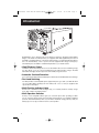
200103046 120V APS MV-cabinetEn-Sp 93-1911.qxd
7/2/01
10:18 AM
Page 1
Owner’s Manual
APS PowerVerter
®
1111 W. 35th Street
Chicago, IL 60609 USA
Customer Support: (773) 869-1234
www.tripplite.com
Alternative Power Sources
(120V, 60 Hz)
• Voltage- and Frequency-Controlled
• Peak Power, High Efficiency
Español: pg. 16
Introduction:
p. 2 - 3
Safety:
p. 4
Configuration & Connection:
Features:
p. 10 - 11
Maintenance & Service: p. 12
Warranty:
p. 12
Troubleshooting:
p. 13
Specifications:
p. 14 - 15
Copyright © 2001 Tripp Lite. All rights reserved.
p. 5-10
200103046 120V APS MV-cabinetEn-Sp 93-1911.qxd
7/2/01
10:18 AM
Page 2
Introduction
Congratulations! You’ve purchased the most advanced, feature-rich integrated inverter/battery
charger on the market. Your APS provides your equipment with utility-supplied AC power when it
is available, and during blackouts, overvoltages and brownouts, your APS automatically switches
over to an external battery source to power connected equipment with voltage and frequencycontrolled AC power. In addition to reliable APS performance, your model features:
• High Efficiency Output
Your APS’s advanced circuitry produces a more efficient DC-to-AC conversion, minimizing energy
loss. This allows you to run connected equipment longer between battery charges. The APS
will maintain this highly-efficient output even as the battery charge decreases.
• Automatic Overload Protection
If you overload your APS, it will automatically protect itself and your valuable batteries from damage.
• Fast Load Switching
Your APS provides an uninterruptible power supply. If AC power goes down, your APS will switch
over to providing battery backup power in 6 milliseconds or less so that your equipment will
operate with no interruption.
• Multi-Function Indicator Lights
Several sets of multifunction indicator lights keep you constantly informed of battery charge
levels, fault conditions and APS operation.
• Multi-Operation Switches
An array of user-configurable switches gives you convenient options when operating your APS.
You can select the voltage level at which your APS’s inverter will turn on to maximize equipment
protection and minimize battery drain; set your APS for maximum charging efficiency with your
battery type; even set up your APS for remote control operation.
2
200103046 120V APS MV-cabinetEn-Sp 93-1911.qxd
Stage
1
Bulk
10:18 AM
Page 3
Advanced, 3-Stage
Battery Charger
Stage 2
Absorption
BATTERY VOLTAGE
7/2/01
Stage 3
Float
Your APS recharges your battery
faster than conventional chargers
because its three-stage charger profile (Bulk, Absorption and Float) are
optimized, regardless of the type of
battery you use (Wet or Gel).* In addition, the advanced charging system
protects against over-charge and
over-discharge to ensure a longer
service life from your battery.
* The Absorption and Float levels vary according to
battery type, which can be set to either “Wet” or “Gel”cell.
TIME
CHARGING PROFILE
• Voltage Regulation (Select models only)
“VR” APS models regulate incoming AC power by automatically “boosting” or “cutting” the voltage
to keep your equipment running through brownouts and overvoltages without draining battery
power.
• Load Sharing (Select models only)
Select APS models can be set to limit their own charging functions so they can charge their
batteries at the quickest rate possible without overloading their power input circuits.
• Frequency-Controlled Inverter Output
All APS models feature Frequency-Controlled Inverter Output which allows devices dependent on
AC line frequency (such as computers, VCRs, CD players, tape recorders, clocks and turntables)
to operate properly.
• Circuit Board Protection
A silicone conformal coating safeguards the circuit boards against moisture.
3
200103046 120V APS MV-cabinetEn-Sp 93-1911.qxd
7/2/01
10:18 AM
Page 4
Safety
This manual contains important instructions and warnings that should be followed during the
installation, operation and storage of all Tripp Lite APS Systems.
APS Location Warnings
• Install your APS indoors, away from excess moisture or heat, dust or direct sunlight.
• Your APS is NOT waterproof. Contact with water can cause the unit to short circuit and
could cause personal injury due to electric shock. Never immerse your APS. Mount it in
the driest location available.
• Leave adequate space around all sides of the APS for proper ventilation. The heavier the
load of connected equipment, the more heat will be generated by the APS.
• Do not install the APS near magnetic storage media, as this may result in data corruption.
Battery Connection Warnings
• Your APS will not operate with or without utility power until batteries are connected.
• Multiple battery systems must be made up of batteries of the same voltage, age, amp
hour capacity and type.
• Keep battery location well ventilated. Explosive hydrogen gas can accumulate near
batteries if they are not kept well ventilated.
• Sparks may result during final battery connection. Always observe proper polarity as batteries are connected.
• Do not allow objects to contact the two DC input terminals. Do not short or bridge these
terminals together. Serious injury to property or person could result.
Equipment Connection Warnings
• Do not use Tripp Lite APS Systems in life support applications where a malfunction or
failure of a Tripp Lite APS System could cause failure or significantly alter the performance
of a life support device.
• Do not connect a surge suppressor, line conditioner or UPS to the output of the APS.
• Corded models: Do not modify the APS's plug in a way that eliminates its ground connection.
Do not use power adapters that will eliminate the plug's ground connection. Connect your
APS only to a properly grounded AC power outlet. Do not plug your APS into itself; this
will damage the APS and void your warranty.
Operation Warnings
• Your APS does not require routine maintenance. Do not open your APS for any reason.
There are no user-serviceable parts inside.
• Potentially lethal voltages exist within this unit as long as the battery supply and/or AC
input are connected. During any service work, the battery supply and AC input connection
(if any) should therefore be disconnected.
• Do not connect or disconnect batteries while the APS is operating from the battery supply.
Dangerous arcing may result.
4
200103046 120V APS MV-cabinetEn-Sp 93-1911.qxd
7/2/01
10:18 AM
Page 5
Configuration
CONFIGURATION DIP SWITCH SETTINGS
DIP SWITCH GROUP A (All models)
BATTERY TYPE / VOLTAGE POINT
Using a small tool, set the 4 “Battery Type / Voltage Point” Configuration DIP Switches, Group A
(located on the front panel of your APS; see Diagram 1, p. 32) to select battery type and set the
voltage range outside of which your APS will switch to battery power.
• Select Battery Type
(DIP Switch #1, Group A)
CAUTION: The Battery Type DIP Switch setting must match the type of batteries you connect or your batteries may be degraded
or damaged over an extended period of time. See “Battery Selection,” page 7 for more information.
Battery Type
Switch Position
Gel Cell (Sealed) Battery ............................Up
Wet Cell (Vented) Battery ............................Down*
4 3 2 1
Gel
Cell
Wet
Cell*
• Select High AC Voltage Switch To Battery Point
(DIP Switch #2, Group A)
Voltage
Switch Position
145V ............................................................Up
135V ............................................................Down*
4 3 2 1
145V
135V*
• Select Low AC Voltage Switch To Battery Point
(DIP Switches #4, Group A & #3, Group A)
4 3 2 1
4 3 2 1
4 3 2 1
4 3 2 1
105V
#4 Up & #3 Up
95V
#4 Up & #3 Down
85V
#4 Down & #3 Up
75V*
#4 Down
& #3 Down
Most loads will perform adequately when your APS’s High AC Voltage Point DIP Switch #2 is set
to 135V and its Low AC Voltage Point DIP Switches #3 and #4 are set to 95V. However, if your APS
frequently switches to battery power due to momentary high/low line voltage swings that would
have little effect on equipment operation, you may wish to adjust these settings. By raising the High
AC Voltage Switch to Battery point and/or lowering the Low AC Voltage Switch to Battery Point, you
may reduce the number of times your APS switches to battery due to voltage swings.
* Factory default settings.
DIP SWITCH GROUP B (Available on Select Models)
LOAD SHARING/EQUALIZE BATTERY CHARGE
Using a small tool, set the “Load Sharing” Configuration DIP Switches, #1 and #2 of Group B
(located on the front panel of your APS; see Diagram 1, p. 32). DIP Switch #3, Group B should
be kept in the “UP” position when you are not equalizing your batteries’ charges. DIP Switch #4,
Group B has different functions, or no function, depending on your APS model.
5
200103046 120V APS MV-cabinetEn-Sp 93-1911.qxd
7/2/01
10:18 AM
Page 6
• Load Sharing
(DIP Switches #1, Group B & #2, Group B)
Your APS features a high-output battery charger that can draw a significant amount of power
from your line power source when charging at its maximum rate. If an APS is supplying its full
AC power rating to its connected load at the same time as it is charging, it could trip its line
source circuit breaker. Tripping this breaker will cut off AC power to your load and stop battery
charging.
To reduce the chance of tripping this breaker, select APS models may be set to automatically
limit their charger output to keep the sum of their AC load and charger power within their
circuit breakers’ rating.
This charger limiting function has four settings, allowing you to choose less charger limiting for
APS configurations with higher rated breakers. The figures below show how to set your DIP
Switches to select how heavy a load can be placed on your APS before charger limiting begins.
4 3 2 1
Most Limiting
#1 & #2 Up*
4 3 2 1
Less Limiting
#1 Down & #2 Up
Battery Charger Limiting Points
Charger limiting begins at when the
4 3 2 1 APS's load reaches 66% of the APS's
Charger limiting takes effect the
moment any load is applied; charger
output falls gradually from full output
at no load to no output at full load.
* Factory default settings.
Charger limiting begins when the
APS's load reaches 33% of the APS's
load rating. Charger output falls
gradually from full output at 33% of
the APS's load rating to about 40% of
full output at full load.
Least Limiting
#1 Up & #2 Down
4 3 2 1
load rating. Charger output falls
gradually from full output at 66% of
the APS's load rating to about 40% of
full output at full load.
No charger limiting occurs at any
load size.
No Limiting
#1 & #2 Down
• Equalize Battery Charge
(DIP Switch #3, Group B)
This DIP Switch is momentarily engaged to begin the process of equalizing the internal resistance
of your battery's cells. This can extend the useful life of certain types of batteries; consult with
your battery's manufacturer to determine if your batteries could benefit from this process. The
charge equalization process is automatic and once started can only be stopped by removing
the input power.
SETTING PROCEDURE:
1) Move to “Equalize” (DOWN) position for three seconds.
2) Move to “Reset” (UP) position and leave it there.
CAUTION: Battery charge equalization should only be performed in strict accordance
with the battery manufacturer's instructions and specifications.
CAUTION: Do not leave DIP switch #3 in the down position after beginning process.
Battery Charge
Switch Position
Reset ............................................................Up*
Equalize ......................................................Down
* Factory default setting.
4 3 2 1
Reset*
Equalize
• Disable Battery Charger (APS 2448 only)
6
(DIP Switch #4, Group B)
If you are connecting the APS 2448 to batteries with a separate charger, you may disable
the APS 2448’s built-in charger with this switch to prevent overcharging.
Disable*
Switch Position
Battery Charger
4 3 2 1
Disable..........................................................Up*
Enable ..........................................................Down
Enable
* Factory default setting.
200103046 120V APS MV-cabinetEn-Sp 93-1911.qxd
7/2/01
10:18 AM
Page 7
• Limit Battery Charger (APS 1012 and APS 2012 only)
(DIP Switch #4, Group B)
To prevent overheating smaller batteries, the charger on these UPS systems is initially set to
deliver only a fraction of its maximum power rating to connected batteries. If you are using
either of these APS systems with a larger battery or battery system (over 100 amp-hours at
12 volts for the APS 1012, over 200 amp-hours at 12 volts for the APS 2012), you may switch
your charger to full power without overheating your batteries.
Switch Position
Battery Charger
Partial (1/3) Charging Power ........................Up*
Full Charging Power ....................................Down
4 3 2 1
1/3 Power*
Full
Power
* Factory default setting.
Battery Selection
Selecting Battery Type
Select a battery or system of batteries that will provide your APS with proper DC voltage and an
adequate amp hour capacity.* Select ‘Deep-Cycle’ batteries to enjoy optimum performance from
your APS. Batteries of either Wet-Cell (vented) or Gel-Cell/Absorbed Glass Mat (sealed) construction
are ideal. 6 Volt “golf-cart, Marine Deep-Cycle or 8D Deep-Cycle batteries are also acceptable.**
* Even though APS models are high-efficiency converters of electricity, their rated output capacities are limited by the amp-hour size
of the external batteries. ** You must set Configuration DIP Switch #1, Group A (Battery Type) to match the type of batteries you
connect or your batteries may be degraded or damaged over an extended period of time. See "APS Configuration," page 5 for more
information.)
Selecting Battery Amp Hour Capacity
Step 1:
Add the Wattage Ratings of your connected equipment to determine the Total Wattage Required.*
Step 2:
Divide the Total Wattage Required (from Step 1) by the battery voltage to determine the DC
Amperes Required.
Step 3:
Multiply the DC Amperes Required (from Step 2) by the number of hours you estimate will pass
without AC power before your battery can recharge to determine a Battery Amp-Hours Required
Rough Estimate.**
Step 4:
Compensate for inefficiency by multiplying your Battery Amp-Hour Required Rough Estimate (from
Step 3) by 1.2 to determine how many amp-hours of battery backup (from one or several batteries)
you should connect to your APS. Note that the Amp-Hour ratings of batteries are usually given for
a 20 hour discharge rate. Actual Amp-Hour capacities are less when batteries are discharged at
faster rates: batteries discharged in 55 minutes provide only about 50% of their listed Amp-Hour
ratings, while batteries discharged in 9 minutes provide as little as 30% of their Amp-Hour ratings.
* The wattage rating is usually stated in the equipment's manuals or on their nameplates. If your equipment is rated in amperes, convert
to watts by multiplying the ampere rating by your nominal AC line voltage (120). ** Your charging amps multiplied by the charging
hours must exceed the discharge amp-hours taken from the batteries between charges or you will eventually run down your battery bank.
7
200103046 120V APS MV-cabinetEn-Sp 93-1911.qxd
7/2/01
10:18 AM
Page 8
Mounting (Optional*)
(See Diagram 2, p. 32).
User must supply all fasteners and brackets and verify their suitability for use with the intended
mounting surface. Turn your APS PowerVerter and connected equipment OFF before mounting.
• Install two 8 mm (1/4 in.) fasteners (A) into a rigid horizontal surface using the measurements
in the diagram. Leave the heads of fasteners raised slightly above the surface in order to
engage the slots in the APS’s feet.
• Slide PowerVerter forward to fully engage the fasteners in the APS’s feet. Install two 8 mm
(1/4 in.) fasteners (B) into the surface, through the slots in the APS’s two unsecured feet.
Tighten the screws to secure the APS in position.
* Horizontal mounting should be used for all vehicular applications. Due to their size and weight, all APS PowerVerter
systems in vehicles should be mounted on a rigid horizontal (not vertical) surface, mounting plate or bracket before
battery connection.
Battery Connection (Standard)
1. Connect your APS’s positive DC Terminal directly to a fuse.
UL recommends that you install a recognized UL component fuse block and fuse within 18 inches
of the battery. The fuse's rating must equal or exceed the Minimum DC Fuse Rating listed in your
APS model's specifications on pages 14 or 15.
2. Choose a battery configuration appropriate to your batteries.
• Single Battery Connection: Refer to Diagram 4, page 33. When using a single battery, its
voltage must be equal to the voltage of your APS's Inverter Nominal Input Voltage (see
specs).
• Parallel Battery Connection: Refer to Diagram 5, page 33. When using multiple batteries in
parallel, each battery's voltage must be equal to the voltage of your APS's Inverter Nominal
Input Voltage (see specs).
• Series Battery Connection: Refer to Diagram 6, page 33. When using multiple batteries in
series, all batteries must be equal in voltage and amp hour capacity, and the sum of their
voltages must be equal to the voltage of your APS's Inverter Nominal Input Voltage (see
specs).
3. Use 2/0 gauge wire ONLY to make external battery connections.
Tighten battery terminals to a torque of 4 N-m.
WARNING! Failure to follow these instructions can lead
to product failure due to excessive heating!
Battery connection cable lengths should be short as possible, and must not exceed the
Maximum Cable Length listed under Specifications, page 14. Shorter and heavier gauge cabling
limits DC voltage drop and allows for maximum transfer of current.* You must tighten your battery
terminals to approximately 4 Newton-meters of torque to create an efficient connection and prevent
excessive heating. Insufficiently tightening terminals could void your PowerVerter's warranty.
*APS models are capable of delivering a much higher wattage output for brief periods of time. Wiring should be configured to
handle this brief high-current draw. Though your APS is a high-efficiency converter of electricity, its rated output capacity is limited
by the length and gauge of the wires running from the battery to the APS.
Battery Connection (DC Vehicular)
APS systems may be permanently mounted in a car, truck or boat and connected to draw power
from the vehicle's battery. Note: An APS can ONLY be connected to vehicle batteries with
voltage that matches the APS's Nominal DC Input—12V vehicle batteries to 12V Nominal DC
Input APS systems, etc. (See Specifications). There are two main ways to make this sort of
8
200103046 120V APS MV-cabinetEn-Sp 93-1911.qxd
7/2/01
10:18 AM
Page 9
vehicular battery connection. Choose the Basic Connection if you are running light hand tools or
other small appliances for a brief period of time (see Diagram 7, p. 34). Choose the Advanced
Connection if you are using your APS to power heavy loads for extended periods of time (see
Diagram 8, p. 34). The Advanced Connection incorporates a battery isolator and separate battery
system to provide battery power to your APS while preventing it from draining your vehicle's
battery. Note: Depending on your application, you may require more than one Deep Cycle Battery.
Caution: Never operate your APS from an alternator without a battery connected as shown in Diagrams 7 or 8, p. 34.
AC Connection
Before AC connection, match the power requirements of your
equipment with the power output of your APS to avoid overload.
When figuring the power requirements of your equipment, do not confuse “continuous” power
ratings with “peak” power ratings. Electric motors require more power to turn on (“peak power”)
than they require to run continuously. “Peak” power ratings are usually 2 to 5 times “Continuous”
ratings. Most electric motors require “peak power” only when they are first turned on. The electric
motors in equipment such as refrigerators and sump pumps, however, constantly turn on and off
according to demand. These motors require “peak power” at multiple, unpredictable times during
their operation.
Hardwired Electrical Connections
(All hardwire models)
(See Diagram 3, p. 32).
Consult a qualified electrician and follow all applicable electrical codes and requirements.
HARDWIRE PROCEDURE
1) Remove screws and cover plate from your APS's Hardwire AC electrical box. Remove the
knockout covers closest to the desired electrical source and to your equipment.
2) Thread your wires through strain reliefs and through the knockouts.
3) Connect both input and output ground wires to the ground (green) terminal.
4) Connect the incoming hot wire to the input hot (brown) terminal.
5) Connect the incoming neutral wire to the input neutral (blue) terminal.
6) Connect the outgoing hot wire to the output hot (black) terminal.
7) Connect the outgoing neutral wire to the output neutral (white) terminal.
8) Tighten and affix strain reliefs. Replace cover plate and tighten screws.
AC Input Electrical Connection
(All corded models)
Plug the line cord into an outlet providing 120V AC, 60 Hz. power. Make sure that the circuit you
connect your APS to has adequate overload protection, such as a circuit breaker or a fuse.
AC Output Electrical Connection
(All corded models)
Simply plug your equipment into the unit's AC receptacles
Set Operating Mode Switch
• Switch to “AUTO/REMOTE” when you are using connected equipment. ADVANTAGE:
Uninterruptible power supply. Provides battery backup power during blackouts or brownouts.
Note: When the switch is in the “AUTO/REMOTE” position, you can operate a user-supplied
switch to transfer between battery-backup and charge-only modes. (See Remote
Connector manual for more information.)
9
200103046 120V APS MV-cabinetEn-Sp 93-1911.qxd
7/2/01
10:18 AM
Page 10
Set Operating Mode Switch continued
• Switch to “CHARGE ONLY” when you are not using connected equipment.
(WARNING! APS will not provide battery backup!) ADVANTAGES: A) Continues to charge
battery when power is present, and B) Turns OFF the APS’s inverter, preventing battery drain
during blackouts or brownouts.
• Switch to “OFF” to completely turn off the APS and connected equipment or to reset the APS
after it has shut down due to overload or overheating.
Switches, Indicator Lights
& Other Features
(See Diagram 9, p. 35 to locate the following switches, indicator lights and other features.)
Switches
1. Operating Mode Switch (All models)
This switch selects the APS operating mode (either “AUTO/REMOTE”, “OFF” or “CHARGE
ONLY”). See “Set Operating Mode Switch”, pg. 10 to select the optimum setting for this switch.
2. “CONFIGURATION SWITCHES”—DIP Switch Group A (All models)
These four switches must be set for the type of battery your APS will be connected to and the voltage
points at which your APS will switch to battery power. See “Configuration”, pg. 5 to select the optimum
settings for these switches.
3. “CONFIGURATION SWITCHES”—DIP Switch Group B (Select models only)
These DIP Switches allow you to equalize the internal resistance of your battery's cells and set the
percentage of your model's maximum load at which the APS will limit battery charging. See
“Configuration”, pg. 7 to select the optimum settings for these switches.
Indicator Lights
4. “LINE” (All models)
This green light will turn continuously ON whenever connected equipment is receiving utility-supplied
AC power and your APS is set to “AUTO/REMOTE”, meaning that it will provide battery backup if
utility power fails. It will flash intermittently when connected equipment is receiving utility power and
your APS's Operating Mode Switch is set to “CHARGE ONLY” to warn you that the APS's inverter
is OFF and that the APS WILL NOT provide battery backup during blackouts, brownouts or overvoltages.
5. “INV” (Inverting—all models)
This yellow light will turn continuously ON whenever connected equipment is receiving batterysupplied AC power (during a blackout, brownout or overvoltage while connected to utility power or
when connected to batteries during vehicular operation).
6. “LOAD” (All models)
This red light will turn continuously ON when the APS’s load is between 80% and 110% of capacity.
The light will flash intermittently when the APS's inverter shuts down due to a severe overload or
overheating. If this happens, turn Operating Mode Switch OFF. Remove the overload and let the
unit cool. You may then turn the APS ON after it cools.
7. “CUT/BOOST” (VR models only)
These lights will turn ON whenever your APS is automatically correcting high (CUT) or low
(BOOST) AC line voltage. This is a normal, automatic operation of your APS that does not drain
battery power, and no action is required on your part.
10
200103046 120V APS MV-cabinetEn-Sp 93-1911.qxd
7/2/01
10:18 AM
Page 11
8. “BATTERY HI/MED/LO” (All models)
These three lights will turn ON in several sequences to show the approximate charge level and
voltage of your connected battery bank and alert you to several fault conditions:
BATTERY CHARGE INDICATION (Approximate)
Indicator
Green
Green & yellow
Yellow
Yellow & red
Red
All three lights off
Flashing red
Capacity
91% - Full
81% - 90%
61% - 80%
41% - 60%
21% - 40%
1% - 20%
0% (Inverter shutdown)
All three lights flash slowly*
All three lights flash quickly**
Excessive discharge
Overcharge
* Approximately 1/2 second on, 1/2 second off. See Troubleshooting section.
** Approximately 1/4 second on, 1/4 second off. May also indicate a battery charger fault exists. See Troubleshooting section.
Other Features
9. DC Input Terminals (All models)
The terminals’ lug screws secure the wires leading from your external battery or battery system.
Your battery or battery system must provide your APS with proper DC voltage and your equipment
with an adequate amp hour capacity. See Battery Selection section, pg. 7 for more information.
10. AC Receptacles: NEMA 5-15R (Corded models only)
These receptacles allow you to connect equipment that would normally be plugged into a utility
outlet. They feature ground fault indicator switches that trip when the receptacles are in danger of
short circuiting. If the switches trip, press to reset them when the short circuit situation is remedied.
11. AC Input Line Cord: NEMA 5-15P fixed (Corded models only)
This cord should be plugged into a 120V, 60 Hz, dedicated 15 Amp AC utility outlet. DO NOT plug
the cord into the APS’s AC receptacles.
12. Hardwire AC Input/Output Terminal Strip (Hardwire models only)
Use the lug screws on these terminals to secure hardwire connections for AC input and output.
See pages 9 & 32 for wiring instructions.
13. Resettable Circuit Breakers (All models)
These circuit breakers protect your APS against damage due to input or output overload. If a
breaker trips, remove some of the load on the APS to prevent overload, then wait 1 minute to allow
components to cool before resetting the circuit breaker.
14. Remote Module Connector (All models)
The front panel of all models has an RJ 45 receptacle for use with the optional remote module.
(Module is included with all VR models.) See the installation instructions packed with the remote
module.
15. Load Sense Potentiometer (All models)
In order to save battery power, the APS’s inverter automatically shuts off when no load is connected.
When the unit detects a load, it automatically turns the inverter on. Users may choose the minimum
load the APS will detect by adjusting the Load Sense Potentiometer. Using a small tool, turn the
potentiometer clockwise to lower the minimum load that will be detected, causing the inverter to
turn on for smaller loads. When the potentiometer is turned fully clockwise, the inverter will operate
even when there is no load. Turn the potentiometer counterclockwise to increase the minimum load
that will be detected, causing the inverter to stay off until the new minimum load is reached.
The factory setting for the potentiometer is fully clockwise, but in areas with frequent power interruptions,
the potentiometer should be adjusted counterclockwise until the inverter is only in operation when
the APS’s load is in use.
11
200103046 120V APS MV-cabinetEn-Sp 93-1911.qxd
7/2/01
10:18 AM
Page 12
Maintenance & Service
Maintenance
Your APS model requires no maintenance but should be kept dry at all times. Periodically check
all cable connections both at the unit and at the battery. Clean and tighten connections as necessary.
Service
If returning your APS to Tripp Lite, please pack the APS carefully, using the ORIGINAL PACKING
MATERIAL that came with the unit. Enclose a letter describing the symptoms of the problem. If the
APS is within the warranty period, enclose a copy of your sales receipt.
Limited Warranty
Tripp Lite warrants its products to be free from defects in materials and workmanship for a period of one year (domestic) or 120
days (export) from the date of initial purchase. Tripp Lite’s obligation under this warranty is limited to repairing or replacing (at its
sole option) any such defective products. To obtain service under this warranty you must obtain a Returned Material Authorization
(RMA) number from Tripp Lite or an authorized Tripp Lite service center. Products must be returned to Tripp Lite or an authorized
Tripp Lite service center with transportation charges prepaid and must be accompanied by a brief description of the problem
encountered and proof of date and place of purchase. This warranty does not apply to equipment which has been damaged by accident,
negligence or misapplication or has been altered or modified in any way. This warranty applies only to the original purchaser who
must have properly registered the product within 10 days of purchase.
EXCEPT AS PROVIDED HEREIN, TRIPP LITE MAKES NO WARRANTIES, EXPRESS OR IMPLIED, INCLUDING WARRANTIES
OF MERCHANTABILITY AND FITNESS FOR A PARTICULAR PURPOSE. Some states do not permit limitation or exclusion of
implied warranties; therefore, the aforesaid limitation(s) or exclusion(s) may not apply to the purchaser.
EXCEPT AS PROVIDED ABOVE, IN NO EVENT WILL TRIPP LITE BE LIABLE FOR DIRECT, INDIRECT, SPECIAL, INCIDENTAL
OR CONSEQUENTIAL DAMAGES ARISING OUT OF THE USE OF THIS PRODUCT, EVEN IF ADVISED OF THE POSSIBILITY
OF SUCH DAMAGE. Specifically, Tripp Lite is not liable for any costs, such as lost profits or revenue, loss of equipment, loss of use
of equipment, loss of software, loss of data, costs of substitutes, claims by third parties, or otherwise.
12
200103046 120V APS MV-cabinetEn-Sp 93-1911.qxd
7/2/01
10:18 AM
Page 13
Troubleshooting
Try these remedies for common APS problems before calling for help. Call Tripp Lite Customer Service at (773)
869-1234 before returning your APS for service.
SYMPTOM
PROBLEMS
CORRECTIONS
APS does not provide
AC output (AC input present)
APS not properly connected to
utility power.
Connect APS to utility power.
Circuit breaker is tripped.
Reset circuit breaker.
APS shutdown due to excessive
battery voltage, indicating possible
Turn APS “OFF”. Wait 1 minute and
switch to “AUTO/REMOTE”.
charger failure. Line disconnected
to prevent permanent battery
damage.
APS does not provide
AC output (AC input absent)
APS will not charge the
battery (AC input present)
APS is set to “OFF”
Set APS to “AUTO/REMOTE” or
“CHARGE-ONLY”.
Circuit breaker is tripped.
Reset circuit breaker.
Operating Mode Switch is set
to “CHARGE ONLY”.
Set Operating Mode Switch to “AUTO/
REMOTE.”
Load or High Temperature fault.
Turn APS “OFF”. Wait 1 minute. Remove
overload. Switch to “AUTO/REMOTE”.
Excessive battery discharge.
Check battery condition.
Connected batteries are dead.
Check and replace old batteries.
Battery fuse* is blown.
Check and replace fuse.
Battery cabling* is loose or degraded.
Check and tighten or replace cabling.
APS charger failure.
Turn APS “OFF”. Wait 1 minute and
switch to “AUTO/REMOTE”. If
automatic shutdown occurs, call Tripp
Lite Customer Service.
All APS Indicator Lights are
OFF (AC input absent)
This is normal if the APS is set
to “CHARGE-ONLY”
—
All APS Indicator Lights are
OFF (AC input is present or
absent)
Excessive battery discharge.
Use an auxiliary charger* to raise
battery voltage. Check external battery
connections and fuse. Automatically
resets when condition is cleared.
All APS Battery Indicator
Lights are slowly flashing.
Excessive battery discharge.
Use an auxiliary charger* to raise
battery voltage. Automatically resets
when condition is cleared.
APS “LO” Battery Light
flashing
Inverter shutdown because battery
voltage dropped too low for more
than 5 seconds. Protects battery
from permanent damage.
Reset by cycling control switch to
“OFF” position then to “AUTO/
REMOTE”.
All APS Battery Lights are
rapidly flashing
then to
High battery voltage shutdown
during Charge mode.
Check all charging sources. Reset by
cycling control switch to "OFF"
“AUTO/REMOTE” or “CHARGE-ONLY”.
APS “LOAD” Indicator Light
is rapidly flashing
Inverter overload caused by
excessive load or short circuit.
If sustained for more then 5
seconds the Inverter is shutdown.
Reset by reducing load and cycling control
switch to “OFF” position then to “AUTO/
REMOTE”.
*User supplied
13
200103046 120V APS MV-cabinetEn-Sp 93-1911.qxd
7/2/01
10:18 AM
Page 14
Specifications (Corded Models)
CORDED MODELS:
Weight:
APS 1012
26.4 lbs.
APS 1024
26.4 lbs.
INVERTER
Continuous power (@ 20° C):
900 W
1000 W
Surge power (5 seconds):
1800 W
2000 W
Efficiency (Full Load):
90%
90%
Minimum DC Fuse Rating:
225A
125A
DC Input Current @ Nominal V DC
Full Load
No Load
95 A
2.2 A*
47 A
1.3 A*
Nominal Input Volts:
12 VDC
24 VDC
DC Input Voltage Range:
10-15 VDC
20-30 VDC
Nominal Output Volts:
120 VAC ±5%
120 VAC ±5%
Nominal Output Frequency:
60 Hz ±.3%
60 Hz ±.3%
BATTERY CHARGER
Charging Capacity DC:
30 A
15 A
Maximum Cable Length
2 ft.
7 ft.
Acceptance Volts VDC:
Selectable
14.4 V**/14.2 V Wet**/Gel
Selectable
28.8 V**/28.4 V Wet**/Gel
Float Volts VDC (w/gel):
13.3 V (13.6 V)
26.6 V (27.2 V)
Input Voltage AC:
120 V
120 V
Input Current AC:
8A
8A
LINE VAC OPERATION
Minimum Input AC Volts:
Selectable 75**,85, 95, or 105 VAC Selectable 75**,85, 95, or 105 VAC
Maximum Input AC Volts
(Continuous, Charger at Maximum):
Selectable 135** or 145 VAC
Selectable 135* *or 145 VAC
Maximum Input Current
(Continuous, Charger at Maximum):
12 A
16 A
Input Frequency:
60 Hz ±10%
60 Hz ±10%
Maximum Output AC (Continuous):
8.3 A
8.3 A
Automatic Transfer Time:
4-6 ms
4-6 ms
*Load sense can reduce this to 1/30 of the listed current. **Factory default setting.
14
200103046 120V APS MV-cabinetEn-Sp 93-1911.qxd
7/2/01
10:18 AM
Page 15
Specifications (Hardwired Models)
HARDWIRED MODELS:
Weight:
INVERTER
Continuous power (@ 20° C):
Surge power (5 seconds):
Efficiency (Full Load):
Minimum DC Fuse Rating:
DC Input Current @ Nominal V DC
Full Load
No Load
Nominal Input Volts:
DC Input Voltage Range:
Nominal Output Volts:
Nominal Output Frequency:
BATTERY CHARGER
Charging Capacity DC:
Maximum Cable Length
Acceptance Volts VDC:
APS 2012
38.0 lbs.
APS2424
41.0 lbs.
2000 W
4000 W
90%
500A
2400 W
4800 W
90%
300A
192 A
2.5 A*
12 VDC
10-15 VDC
120 VAC ±5%
60 Hz ±.3%
112 A
1.5 A*
24 VDC
20-30 VDC
120 VAC ±5%
60 Hz ±.3%
60 A
1 ft.
Selectable
14.4 V**/14.2 V Wet**/Gel
30 A
3 ft.
Selectable
28.8 V**/28.4 V Wet**/Gel
Float Volts VDC (w/gel):
13.3 V (13.6 V)
26.6 V (27.2 V)
Input Voltage AC:
120 V
120 V
Input Current AC:
16 A
16 A
LINE VAC OPERATION
Minimum Input AC Volts:
Maximum Input AC Volts
(Continuous, Charger at Maximum):
Maximum Input Current
(Continuous, Charger at Maximum):
Input Frequency:
Maximum Output AC (Continuous)
Automatic Transfer Time:
Selectable 135** or 145 VAC
Selectable 135** or 145 VAC
32 A
60 Hz ±10%
16.7 A
4-6 ms
36 A
60 Hz ±10%
20 A
4-6 ms
HARDWIRED MODELS (Cont.):
Weight:
APS 2448
38.0 lbs.
APS3636VR
56.9 lbs.
2400 W
4800 W
90%
300A
3600 W
7200 W
89%
300A
56 A
1.5 A*
48 VDC
40-60 VDC
120 VAC ±5%
60 Hz ±.3%
114 A
1.7 A*
36 VDC
30-45 VDC
120 VAC ±5%
60 Hz ±.3%
15 A
12 ft.
Selectable
57.6 V**/56.8 V Wet**/Gel
53.2 V (54.4 V)
120 V
16 A
30 A
4.5 ft.
Selectable
43.2 V**/42.6 V Wet**/Gel
39.9 V (40.8 V)
120 V
24 A
INVERTER
Continuous power (@ 20° C):
Surge power (5 seconds):
Efficiency (Full Load):
Minimum DC Fuse Rating:
DC Input Current @ Nominal V DC
Full Load
No Load
Nominal Input Volts:
DC Input Voltage Range:
Nominal Output Volts:
Nominal Output Frequency:
BATTERY CHARGER
Charging Capacity DC:
Maximum Cable Length
Acceptance Volts VDC:
Float Volts VDC (w/gel):
Input Voltage AC:
Input Current AC:
LINE VAC OPERATION
Minimum Input AC Volts:
Maximum Input AC Volts
(Continuous, Charger at Maximum):
Maximum Input Current
(Continuous, Charger at Maximum):
Input Frequency:
Maximum Output AC (Continuous)
Automatic Transfer Time:
Selectable 75**,85, 95, or 105 VAC Selectable 75**,85, 95, or 105 VAC
Selectable 75**,85, 95, or 105 VAC Selectable 75**,85, 95, or 105 VAC
Selectable 135** or 145 VAC
Selectable 135** or 145 VAC
33 A
60 Hz ±10%
20 A
4-6 ms
54 A***
60 Hz ±10%
30 A
4-6 ms
*Load sense can reduce this to 1/30 of the listed current. **Factory default setting. ***When AVR is boosting incoming current.
15
200103046 120V APS MV-cabinetEn-Sp 93-1911.qxd
7/2/01
10:18 AM
Page 32
Diagrams/Esquemas
1.2
1.1
1
See “Configuration”, pg. 5. 1.1 is DIP Switch Group A. 1.2 is DIP Switch Group B.
Refiérase a la sección “Configuración”, página 20. 1.1 representa el Grupo A de Interruptores DIP. 1.2 representa
el Grupo B de Interruptores DIP
2
3
3.3
3.4
3.5
3.6
3.7
3.2
3.1
See Hardwire Electrical Connections, pg. 9. 3.1 is the
cover plate, 3.2 is the five-position terminal strip, 3.3 is
the output neutral (white), 3.4 is the output hot (black), 3.5
is the ground (green), 3.6 is the input neutral (blue) and
3.7 is the input hot (brown).
Refiérase a la sección “Conexiones Eléctricas Directas al
Circuito”, página 24. 3.1 representa la cubierta;
3.2 representa la barra de terminales de 5 posiciones;
3.3 representa la terminal neutra de salida (blanca);
3.4 representa la terminal positiva de salida (negra);
3.5 representa la terminal de conexión a tierra (verde);
3.6 representa la terminal neutra de entrada (azul) y
3.7 representa la terminal positiva de entrada (café).
32
200103046 120V APS MV-cabinetEn-Sp 93-1911.qxd
7/2/01
10:18 AM
Page 33
4
X Volts
4.1
APS
See Battery Connection, Pg.8. 4.1 is the fuse. X = Your APS's Inverter's Nominal Input Voltage. (See specs.)
Refiérase a la sección “Conexión de Baterías”, página 23. 4.1 representa el fusible. X = El Voltaje Nominal de
Entrada del Inversor del APS. (Vea las especificaciones).
5
5.1
X Volts
X Volts
X Volts
APS
X Volts
See Battery Connection, Pg.8. 5.1 is the fuse. X = Your APS’s Inverter's Nominal Input Voltage. (See specs.)
Refiérase a la sección “Conexión de Baterías”, página 23. 5.1 representa el fusible. X = El Voltaje Nominal de
Entrada del Inversor del APS. (Vea las especificaciones).
6
X/2 Volts
6.1
X/2 Volts
APS
See Battery Connection, Pg.8. 6.1 is the fuse. X = Your APS’s Inverter's Nominal Input Voltage. (See specs.)
Refiérase a la sección “Conexión de Baterías”, página 23. 6.1 representa el fusible. X = El Voltaje Nominal de
Entrada del Inversor del APS. (Vea las especificaciones).
33
200103046 120V APS MV-cabinetEn-Sp 93-1911.qxd
7/2/01
10:18 AM
Page 34
7
7.1
12V
7.3
7.4
7.2
APS
Basic 12VDC Vehicular Battery Connection. See Pg.8.
7.1 is the alternator. 7.2 is the vehicle battery ground. 7.3 is the vehicle battery. 7.4 is the fuse.
Conexión Básica de Baterías de 12V de CD en Vehículos. Vea página 23.
7.1 representa el alternador. 7.2 representa la conexión a tierra de la batería del vehículo.
7.3 representa la batería del vehículo. 7.4 representa el fusible.
8
12V
8.1
8.2
8.3
8.6
8.4
APS
12V
8.5
8.3
Advanced 12VDC Vehicular Battery Connection. See Pg.8.
8.1 is the alternator. 8.2 is a battery isolator. 8.3 is the vehicle battery ground. 8.4 is an
auxiliary vehicle battery. 8.5 is the vehicle battery. 8.6 is the fuse.
Conexión Avanzada de Baterías de 12V de CD en Vehículos. Vea página 23.
8.1 representa el alternador. 8.2 representa el aislador de la batería. 8.3 representa la
conexión a tierra de la batería. 8.4 representa la batería auxiliar del vehículo.
8.5 representa la baterÍa del vehiculo. 8.6 representa el fusible.
34
200103046 120V APS MV-cabinetEn-Sp 93-1911.qxd
7/2/01
2
8
10:18 AM
14 4
5
6
Page 35
1
9
15
A. Corded Model
Modelo con Cable
13
16
9
10
11
B. Hardwired Model
Modelo con Toma Directa al Circuito
7
3
2
8
14
4
5
6
1
15
13
1. Interruptor “Operating Mode”
(Modo de operación)
2. Grupo A de Interruptores DIP
(Todos los modelos)
12
3. Grupo B de Interruptores DIP
(Modelos selectos únicamente)
4. “LINE” (Línea)
(Todos los modelos)
5. “INV” (Inversor )
(Todos los modelos)
6. “LOAD” (Carga Conectada)
7. “CUT/BOOST” (disminuyendo / elevando)
(Modelos VR solamente)
8. “BATTERY HI/MED/LO”
(Carga de Baterías Alta/Media/Baja)
(Todos los modelos)
9
1. Operating Mode Switch (All models)
2. DIP Switch Group A (All models)
3. DIP Switch Group B (Select models only)
9. Terminales de Entrada de CD (Todos los modelos)
4. “LINE” (All models)
10. Receptáculos de CA
(Solamente en los modelos con cable de CA)
5. “INV” (Inverting—all models)
11. Cable de Línea de CA
(Solamente en los modelos con cable de CA)
7. “CUT/BOOST” (VR models only)
12. Barra de Terminales de Toma Directa a Entrada/Salida
de CA (Modelos con toma directa al circuito solamente)
9. DC Input Terminals (All models)
13. Interruptores de Circuito con Restablecimiento
14. Conector para el Módulo de Control Remoto
(Todos los modelos)
15. Potenciómetro Sensor de Carga Conectada
(Todos los modelos)
6. “LOAD” (All models)
8. “BATTERY HI/MED/LO” (All models)
10. AC Receptacles (Corded models only)
11. Fixed AC Input Line Cord fixed (Corded models only)
12. AC Input/Output Terminal Strip (Hardwire models only)
13. Resettable Circuit Breakers (All models)
14. Remote Module Connector (All models)
15. Load Sense Potentiometer (All models)
35
200103046 120V APS MV-cabinetEn-Sp 93-1911.qxd
7/2/01
10:18 AM
Page 36
1111 W. 35th Street
Chicago, IL 60609 USA
Customer Support: (773) 869-1234
www.tripplite.com
93-1911 (200103046)
36