1
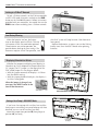
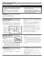
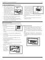
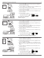
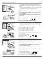
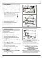
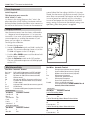
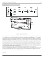
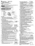
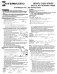
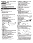
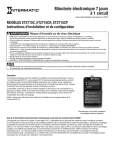
MODEL CA8900 Z-Wave®
Digital Thermostat
Installation and User Instructions
Description and Features
The CA8900 is a digital thermostat that can be controlled wirelessly with Z-Wave controllers supporting
the Thermostat General V2 Device Class. The thermostat is compatible with all standard 24 VAC heating
and cooling systems, up to two-stage heat, one-stage
cool, and two-stage heat pump. The CA8900 operates
as a simple thermostat with buttons to set target temperatures for heat and cool modes. The Save Energy
button adds two more modes for target temperatures
to provide a single button set-back mode for easy operation. It can easily be retrofitted to existing systems
as part of a Z-wave control strategy.
The CA8900 Wireless Thermostat provides two-way
communication as part of a Z-Wave® network. When
it receives commands from the Central Controller
Unit, it sends back confirmation that the command
was received and implemented. Each module in a
Z-Wave network communicates with every other module, acting as a “repeater”
and routing your commands
to their destination by the most reliable pathway.
When Z-Wave devices (regardless of manufacturer)
are installed throughout the house, signals are automatically routed around obstacles or dead spots,
strengthening the network as more devices are added.
The Z-Wave icon shows on the lower right of the display panel, indicating that the thermostat is in contact
with the controller. If the icon is not present, communication has been lost. If this occurs, all remote HVAC
functions are shut off.
•This thermostat can be used with all 24VAC heating and cooling systems. It cannot be used with line
voltage systems.
•The CA8900 is digital and your desired heat or cool
temperatures can easily be set on the large screen
with the TEMP UP (+) and TEMP DOWN (-) buttons
on the front.
•A minimum 4-minute off time protects heating and
cooling systems from damage.
•This thermostat uses a new technique called sequential staging for more comfort with faster reaction to
requested temperature changes.
NOTE: When using a heat pump with auxiliary
heat, if the heat pump cannot keep up and/or is
defective, remove jumper from position 2B and put
jumper on position 2A. This will make the auxiliary
heat your only source of heat. Be sure to restore it
to PUMP when the pump is again operational, as
auxiliary heat is more expensive than pump heat.
For more information, see page 3.
This guide is in two parts:
•Part One: Operating Guide —
for the homeowner or end user.
•Part Two Installing Guide —
for the installer or technician.
2
CA8900 Z-Wave® Thermostat Installation Guide
Part One: Operating Guide
Operating the CA8900
To set the thermostat to control your heating system,
press the HEAT button so the word HEAT displays.
Press again to turn OFF. The word HEAT will flash
when the thermostat is calling for heat.
Press the TEMP UP and TEMP DOWN buttons to select
the desired temperature. The word TARGET will be
displayed with the temperature you are setting. (The
display will return to showing room temperature in 5
seconds.)
To set the thermostat to control your cooling system,
press the COOL button so the word COOL displays.
Press again to turn OFF. The word COOL will flash
when the thermostat is calling for cooling.
•Slide the fan switch to AUTO to automatically run
the system’s fan during heating and cooling.
•Slide the fan switch to ON to run the fan continuously, even without heating and cooling.
Using the SAVE ENERGY Button
The NORMAL and SAVE ENERGY buttons allow you to
quickly switch from the NORMAL programmed target
temp to a pre-determined set-back temperature, called
the Save Energy temp.
•When in HEAT mode:
a. Press the SAVE ENERGY button. The words SAVE
and TARGET appear.
b. Press the TEMP UP or TEMP DOWN buttons to set
the SAVE ENERGY temperature for heating, or
you can accept the default temperature of 65°F.
After 5 seconds, the display shows the room
temperature and the words SAVE HEAT.
•When in COOL mode:
a. Press the SAVE ENERGY button. The words SAVE
and TARGET appear.
b. Press the TEMP UP or TEMP DOWN buttons to set
the SAVE ENERGY temperature for cooling, or
you can accept the default temperature of 80°F.
After 5 seconds, the display shows the room
temperature and the words COOL SAVE.
Press the NORMAL button to return to the programmed target heat or cool temperature, (depending on which mode you are in). You can press the
TEMP UP or TEMP DOWN buttons to change this target
temperature. After 5 seconds, the display shows room
temperature.
Providing a brighter solution.™
3
CA8900 Z-Wave® Thermostat Installation Guide
Joining to a Z-Wave® Network
To join a Z-Wave network, set the Z-Wave controller
to INCLUDE mode, then press and release the BIND
button on the CA8900 thermostat. Follow instructions
provided with your controller. You would also use the
BIND button when excluding from a Z-Wave network.
Low Battery Warning
When the batteries are low, the battery
icon on the display panel will flash. The two
AA batteries in the unit need to be replaced.
These batteries are not for operation, but
provide battery backup for your settings. The
thermostat requires 24VAC for operation, and
the HVAC system will stop function if the thermostat
loses power.
Replace the batteries as soon as you see the flashing
battery icon. Press the RESET button after replacing
batteries.
Fahrenheit / Celsius
Indicator
Displaying Fahrenheit or Celsius
Whether the temperature display panel displays in
Fahrenheit or Celsius depends on the position of the
F/C jumper. The F/C jumper is at the top right of the
PCB, called Jumper 4 in the diagram below.
•With the jumper removed, the display is in Fahrenheit (the default setting).
Current Temperature
Display
SET Temperature
Display
•With the jumper placed on both pins, the display is
in Celsius (centigrade).
JP1
When the jumper is changed, you
must press the RESET button on the
front of the thermostat.
JP5
A
B
1
JP3
2
JP2
5
4
JP4
3
Celsius/Fahrenheit Jumper
Setting a Heat Pump’s AUX ONLY Mode
If you have a heat pump with auxiliary heat and the
heat pump is not working or cannot keep up with heat
demand, you can use the auxiliary heat only.
Move the jumper from position 2B [heat pump] to
position 2A [Aux only].
JP1
JP5
A
B
Heat Pump/
Aux Only
Providing a brighter solution.™
JP3
2
JP4
JP2
4
CA8900 Z-Wave® Thermostat Installation Guide
Part Two: Installing Guide
WARNING–Risk of Fire or Electric Shock
• To avoid fire, shock, or death, and to prevent damage to the furnace,
air conditioner, and thermostat, disconnect the power supply before
beginning work. This can be done at the circuit breaker, or at the
appliance.
• Do not short (jumper) across electric terminals at control on
furnace or air conditioner to test the system. This will damage the
thermostat and void your warranty.
• Your thermostat is a precise instrument, handle it with care.
• This thermostat is designed for use with 24 volt AC systems. The
thermostat should be limited to a maximum of 1.0 amps; higher
amperage may cause damage to the thermostat.
• Do not turn electricity back on until work is completed.
• All wiring must conform to local codes and ordinances.
Tools Needed
•#1 Phillips screwdriver (small)
•Drill with 3/16-in. (4.8mm) bit
1 – Location of Thermostat
Replacement installations—mount the new thermostat
in place of the old one.
New installations—follow the guidelines listed below.
•Locate the thermostat on an inside wall, about 5 ft.
(1.5m) above the floor, and in a room that is used
often.
Good
•Do not install it
where there are
unusual heating
conditions, such
as: in direct
sunlight; near
a lamp, radio,
•Do not locate in unusual cooling conditions, such
as: on a wall separating an unheated room; or in a
draft from a stairwell, door, or window.
•Do not locate in a damp area. This can lead to corrosion that will shorten thermostat life.
•Do not locate where air circulation is poor, such as:
in a corner or an alcove; or behind an open door.
•Do not install the unit until all construction work
and painting has been completed.
5ft.
(1.5m)
•This thermostat does not require leveling.
2 – Label Wires from Old Unit
2. Attach labels (enclosed) to each wire for identification.
IMPORTANT : LABEL ALL
WIRES BEFORE DISCONNECTING THEM!
W
B
G
Switch electricity to the furnace
and air conditioner OFF; then
proceed with the following steps.
television, radiator register, or fireplace; near hot
water pipes in a wall; near a stove on the other side
of a wall.
1. Remove cover from old thermostat. Most are snapon types and simply pull off. Some have locking
screws on the side or front. These must be loosened. Note the letters printed near the terminals.
3 – Remove Old Unit
1. Label the wires one at a time. You must label all the
wires before you proceed.
2. With all wires labeled, remove them from the old
unit.
NOTE: Read instructions carefully before removing any wiring from existing thermostat. Wires
must be labeled before they are removed. THERE
IS NO STANDARD COLOR CODE. When removing wires from their terminals, ignore the color of
the wires since these may not comply with any
standard.
NOTE: Make sure the wires do not fall back inside the wall. You can wind them around a pencil
to keep them from falling.
3. Loosen all screws on the old thermostat and remove it from the wall.
4. Fill wall opening with non-combustible insulation
to prevent drafts.
Providing a brighter solution.™
5
CA8900 Z-Wave® Thermostat Installation Guide
4 – Mount the CA8900 Thermostat
1. Separate front from back of
unit. Grasp the thermostat
and pry the body away from
the base, lift up to remove
the body from the base. Set
aside the control unit.
Control unit
[body]
2. Hold the base against the
wall, with the wires coming
through the opening below the terminal block.
3. Thread wires through the hole in the thermostat
base. Take care not to “short” wires.
4. Position the base for best appearance. Mark the
holes in pencil for drilling or mount directly to the
wall with the two screws provided.
5. If you are mounting the
base to drywall or if you
are using the old mounting holes, use the plastic
anchors provided. Drill
a 3/16-in. (4.8mm) hole
for the insert at each
screw location, and then
mount the base.
Terminal
Block
Hole in
wall
Thermostat Base
6. Thread wires through the hole in the thermostat
base.
7. Leave wires loose in the opening, take care that
they do not “short.”
Before You Connect Wires
Please follow these guidelines for safe and secure wire
connections.
•Use the Step-By-Step diagram as
your guide.
•Strip 3/8” of the wire and form as
shown
•Take care not to damage the labels for each wire in
handling.
•Fan wires out as illustrated with CA8900 below the
wall opening.
•Wires will dress behind the CA8900 and up over the
terminal area.
Which wires do you have?
•Determine which step-by-step wiring diagram you
should use from the next pages. Make sure your
wires are labeled. This may require you to find the
‘other end’ connection for each wire on your heating or air conditioning equipment and read the label
there.
4 5 (24VAC) for the
•You must have a wire marked “C”
1 2
CA8900 to operate. Without
the 24VAC power, the
3
CA8900 will run on its back-up batteries for just a
few days.
Jumpers
•Do not bunch wires behind CA8900. Feed slack
back into the wall opening.
•Connect labeled wires only to a terminal with corresponding letter.
CAUTION: Do not allow wires to touch each other
or parts on thermostat.
•Insert the wire in the terminal and tighten the screw
securely.
•You will need to
set Configuration Jumpers
per the Step-ByStep diagram. A
4 5
1 2
3
Jumpers
Providing a brighter solution.™
6
CA8900 Z-Wave® Thermostat Installation Guide
5 – Find and Use the Set-Up Diagram for Your System
Find the reference page with your wiring diagram and
jumper set-up information. Remember, the C wire
[24vac power] is not optional.
2 WIRE HEAT
+C
1. Connect the R (or RH) wire to the RH terminal on the CA8900.
This connects the Heater Power to the thermostat.
WIRES:
C W RH
From e
Furnac
2. Connect the W wire to the W on the CA8900. This connects the
heater control line to the CA8900.
2 Wire
Heat +C
W
C
3. Connect the C wire to the C terminal on the CA8900. This connects 24vac power.
RH
4. Set Config jumpers as shown.
-- If you have Electric heat, set 1A.
Go To Page 8
C
OPTIONAL POWER
-- If you have Gas or Oil, set 1B.
R
W
If your combination of wires is not shown here, you
can use the Wiring Reference Guide beginning on
page 11 to determine your connections, or contact
Customer Service for help.
1
A
2
3
4
5
B
Your system is now connected. Continue on page 9.
C B O W2 W Y
RH RC G A
CA8900 Terminals
3 Wire Zoned
Hot Water
+C
1. Based on your valve type:
WIRES:
W RH A
3 Wire
Zoned
Hot Water +C
From e
Furnac
W
RH
A
-- Solenoid valve -Connect the R (or RH) wire to the RH terminal
on the CA8900. Connect the W wire to the A terminal on the
CA8900. Connect the remaining wire to the W terminal.
C
Motor15
Valve
Go To Page
C
W R
-- Motor driven Valve - Connect the R (or RH) wire to the RH terminal on the CA8900. Connect the W wire to the W terminal
on the CA8900. Connect the remaining wire to the A terminal.
A
2. Connect the C wire to the C terminal on the CA8900. This connects 24vac power.
1
2
3
3. Set Config jumpers as shown.
C B O W2 W Y
CA8900 Terminals
RH RC G A
Your system is now connected.
Continue on page 9.
Providing a brighter solution.™
4
5
7
CA8900 Z-Wave® Thermostat Installation Guide
WIRES:
1. Connect the R (or RH) wire to the RH terminal on the CA8900. This
connects to the Heater Power.
C W RH G
3 Wire
Heat
+C
From
Furnace
3 Wire
Heat +C
2. Connect the W wire to the W terminal on the CA8900. This connects the heater control line to the CA8900.
3. Connect the G wire to the G terminal on the thermostat. This connects the Fan to the CA8900
W
C
G
RH
4. Connect the C wire to the C terminal on the CA8900. This connects 24vac power.
Go To Page HVAC
9 SYSTEM
W R
C
OPTIONAL POWER
5. Set Config jumpers as shown.
G
-- If you have Gas or Oil, set 1B.
C B O W2 W Y
RH RC G A
CA8900 Terminals
C W Y RH G
From e
Furnac
C
W
4 Wire
Heat/Cool
+C
RH
Y
5
B
Your system is now connected.
Continue on page 9.
4. Connect the G wire to the G terminal on the Thermostat. This
connects to the Fan.
G
5. Connect the C wire to the C terminal on the CA8900. This connects 24vac power.
6. Set Config jumpers as shown.
RH RC G A
CA8900 Terminals
4
3. Connect the RH or R wire to the RH terminal on the thermostat.
This connects the Heater/Cool Power.
Go To HVAC
Page
10
SYSTEM
C B O W2 W Y
3
2. Connect the Y wire to the Y terminal on the CA8900. This connects to the Cool compressor.
G
C W Y R
2
1. Connect the W wire to the W terminal on the thermostat. This connects to the heater control line.
WIRES:
4 Wire
Heat/Cool
+C
1
-- If you have Electric heat, set 1A. A
-- If you have Electric heat set 1A.
-- if you have Gas or Oil set 1B.
1
A
2
3
4
5
B
Your system is now connected. Continue on page 9.
5
Wire
Heat/
Cool
+C
1. Connect the W wire to the W terminal on the thermostat. This
connects to the heater control line.
WIRES:
C W Y RH RC G
From e
Furnac
C
W
5 Wire
Heat/Cool
+C
Y
RH
RC
G
Go To Page
11
HVAC SYSTEM
C W Y RH RC G
2. Connect the Y wire to the Y terminal on the CA8900. This connects to the Cool compressor.
3. Connect the RH wire to the RH terminal and the RC wire to the
RC terminal on the CA8900. This connects the Heater and Cool
Power.
4. Connect the G wire to the G terminal on the Thermostat. This
connects to the Fan.
5. Connect the C wire to the C terminal on the CA8900.This connects 24vac power.
6. Set Config jumpers as shown.
C B O W2 W Y
CA8900 Terminals
RH RC G A
-- If you have Electric heat set 1A.
-- If you have Gas or Oil set 1B.
1
A
2
3
4
B
Your system is now connected. Continue on page 9.
Providing a brighter solution.™
5
8
CA8900 Z-Wave® Thermostat Installation Guide
WIRES:
4 Wire
Heat
Pump
w/o
Aux
+C
C B or O Y R H G
From e
Furnac
4 Wire Heat Pump
w/o Aux Heat +C
B
C
O
Y
RH
1. Connect O wire to the O terminal or B wire to the B terminal
on the CA8900. (If you have both O and B, connect O wire to O
terminal
DO NOT connect B to B terminal. (See page 10 Trane for the B
wire terminal.) This connects the change-over valve.
2. Connect the Y wire to Y on the CA8900. This connects the Compressor.
G
3. Connect the R (or RH) wire to RH on the CA8900. This connects
to the 24vac power.
4. Connect the G wire to the G terminal on the CA8900. This connects the Fan.
HEAT PUMP SYSTEM
C
O
or
B
Y RH G
5. Connect the C wire to the C terminal on the CA8900. This connects 24vac power.
3
4 5
1
2
or
C B O W2 W Y
RH RC G A
6. Set Config jumpers as shown.
CA8900 Terminals
Your system is now connected. Continue on page 9.
5 Wire
Heat
Pump
w/ Aux
Heat +C
WIRES:
C B or O W 2 Y R H G
5 Wire
Heat Pump
w/ Aux Heat
+C
From
Furnace
B
C
O
Y
W2
RH
2. Connect the W2 wire to W2 on the CA8900.
4. Connect the R wire to RH on the CA8900.
5. Connect the G wire to G on the CA8900.
6. Connect the C wire to the C terminal on the CA8900. This connects 24vac power.
HEAT PUMP SYSTEM
C O
or
B
Y R
W2
G
7. Set Config jumpers as shown.
or
C B O W2 W Y
1
2
3
4
5
8. Set jumper 5 if you have Gas
or Oil aux heat.
RH RC G A
Your system is now connected. Continue on page 9.
CA8900 Terminals
WIRES:
2 Stage
Heat and
1 Stage
Cool +C
C W2 W Y R H G
From e
Furnac
C
W2
1 stage Cool
2 stage Heat
+C
W
Y
RH
G
HVAC SYSTEM
C
W2
W
Y
RH
G
C B O W2 W Y
1. Connect the W wire to the W terminal and W2 to W2 on the
CA8900. This connects 2 stages of heat.
2. Connect the Y wire to the Y terminal wire on the CA8900. This
connects cool.
3. Connect the RH or R wire to the RH terminal on the thermostat. This
connects the Heater/Cool Power.
4. Connect the G wire to the G terminal on the Thermostat. This
connects to the Fan.
5. Connect the C wire to the C terminal on the CA8900. This connects 24vac power
6. Set Config jumpers as shown.
OPTIONAL
POWER
CA8900 Terminals
DO NOT connect B to B terminal. See page 10 Trane for B
wire terminal.
3. Connect the Y wire to Y on the CA8900.
G
or
OPTIONAL POWER
1. Connect O wire to the O terminal or B wire to the B terminal on the
CA8900. If you have both O and B, connect O wire to O terminal.
-- If you have Electric heat, set 1A.
RH RC G A
-- If you have Gas or Oil, set 1B.
1
A
2
3 4
B
Your system is now connected. Continue on page 9.
Providing a brighter solution.™
5
9
CA8900 Z-Wave® Thermostat Installation Guide
6 – Install AA Batteries
While the CA8900 requires the C wire (24VAC) to
operate. It also requires 2AA batteries to back-up the
24VAC power for up to a few days.
+ AA
-
+
AA
-
1. Install 2 AA alkaline batteries according to the polarity noted in the compartment. LCD segments will go
on.
2. Press the RESET button (on front of the thermostat)
to clear transient program memory.
NOTE: Replace the batteries when
this LOW battery indicator appears
on the display or once a year.
COOL
When you have finished inserting the batteries:
1. Attach control unit to wall unit.
2. Hook the top of the body onto the base.
3. Swing the body down, and
4. Snap the body onto the base.
7 – Check Out the CA8900 Unit
TEMP UP
Follow these procedures to verify you have correctly
installed the CA8900.
Turn power to the system back on.
COOL
To check Fan: (If you connected the G wire – fan relay)
1. Slide the FAN switch to the ON position.
2. Verify that air is blowing from the system.
RESET
NORMAL
3. Return to AUTO position for normal operation.
To check HEAT mode:
1. Press HEAT button, setting the mode to HEAT. The
word HEAT displays.
2. Slide the FAN switch to AUTO.
3. Using the TEMP UP (+) button, raise the Target Temp
to 90° F.
4. Allow the system 2 min to respond.
5. Verify that heat is blowing from the system.
6. Press the HEAT button to shut heat off.
To check COOL mode:
1. Press the COOL button, setting the mode to COOL.
The word COOL displays.
2. Slide the FAN switch to AUTO.
TEMP
DOWN
SAVE
ENERGY
HEAT
Button
HEAT
AUTO
COOL
ON
FAN
COOL
Button
Fan
3. Press the TEMP DOWN (–) button to a temp 5 degrees below the room temp.
4. Allow the system 2 minutes to respond.
5. Verify that cool air is blowing from the system.
6. Press the COOL button to shut cooling off.
Congratulations, you have successfully
installed your unit.
Please proceed to the OPERATING Guide
to initialize the CA8900.
NOTE: If you have labeled your wires, followed the
correct Step-By-Step, and these Check procedures do
not operate your system, call Customer Support.
Providing a brighter solution.™
10
CA8900 Z-Wave® Thermostat Installation Guide
Power Requirement
24VAC Required!
This thermostat must run on the
HVAC 24VAC (C) wire.
As shown in the wiring diagrams, the C wire is the
other side of the 24VAC heating transformer and can
be found where the other thermostat wires connect at
the wall or at the furnace. Do not use the common or
ground side of the line voltage. With the C wire connected, the thermostat will continue to work if the batteries die or are removed. The batteries are for back-up
in case of power loss and only will last a few days.
In case of total power loss the NORMAL and SAVE
energy settings will return to their default settings (see
operation guide) when power is reapplied.
Changing Calibration
Your thermostat comes from the factory calibrated to
+/- 1 degree of actual temperature. It is an accurate
instrument. If you want your thermostat to display the
same temperature as another thermometer in your
home, you can adjust its calibration.
To change the calibration:
1. Remove the top cover.
2. Locate the Calibration switch and slide it to the ON
position. The current calibration factor (+/-) of the
CA8900 will appear in the LCD display.
OFF
ON
3. Push the UP or DOWN arrows until the desired calibration factor is reached.
Calibrate
switch
4. Slide the Calibration switch to the OFF position.
The new calibrated temperature will be displayed
on the LCD.
Wire Reference Guide
Your Wires Intermatic Terminal
Your Wires Intermatic Terminal
R or V or V RH or 4 RC W
W2 ?
Y
Y2 G or F C or X R RH and RC Single power for HEAT and COOL
RH Power for HEAT (RH not connected to RC)
RC Power for COOL (RH not connected to RC)
W Heat control
W2 2nd stage HEAT or heat pump auxiliary heat
A 3rd wire for zoned hot water heat (see zoned)
Y COOL control
2nd stage COOL control (do not connect; tape off)
G FAN control
C Common 24VAC power (to power thermostat)
Lennox Heat Pump
Your Wires V or VR or R M or Y Y or W or W2 F or G R or O X or X2 or C C
Intermatic Terminal
RH
Y
W2
G
O
Trane Products (Amer Std)
Your Wires B
W or W1 Intermatic Terminal
C
W2
E
L
T
B or O
B and O Emergency heat (do not connect, tape off)
System monitor (do not connect, tape off)
Outdoor sensor (do not connect, tape off)
B Heat pump changeover
(cool to heat, powered in heat)
O Heat pump changeover
(heat to cool, powered in cool)
If there are both B and O wires
(Trane pump products). DO NOT CONNECT B to B
terminal, connect B to C terminal.
Zoned Systems
Your Wires Intermatic Terminal
2 wire Zoned Hot Water
R
RH
W
W
3 Wire Zoned Hot Water Motor Driven Valves
R
RH
W
W
Y (the 3rd wire) A
3 Wire Zoned Hot Water Solenoid Valves
R
RH
W
A
Y (the 3rd wire) W
Providing a brighter solution.™
11
CA8900 Z-Wave® Thermostat Installation Guide
Jumper Reference
FAN
JP 5
HEAT PUMP
JP3 TYPE
1
ELECT
H-PUMP
1B
GAS/OIL
FURN
NO JUMPER
NO FAN
JP 4
HPAUX
TYPE
JP1
JP2
2A
1A
C/F
POWER
AUX HEAT
ONLY
3
2
RC-RH
CONCTED
Celsius
4
RC-RH
SEPARATE
2B
HEAT PUMP
WITH AUX
5
Fahrenheit
GAS/OIL
AUX
ELECTRIC
AUX
JUMPER
ON
REMOVED
NO JUMPER
NORMAL
JP1
4
JP5
A
B
FAN
CONTROL
1
Heat Pump/
Aux Only
JP3
2
JP2
5
HP AUX
TYPE
Celsius/
Fahrenheit
JP4
3
POWER
LIMITED ONE-YEAR WARRANTY
If within one (1) year from the date of purchase, this product fails due to a defect in material or workmanship, Intermatic Incorporated will
repair or replace it, at its sole option, free of charge. This warranty is extended to the original household purchaser only and is not transferable. This warranty does not apply to: (a) damage to units caused by accident, dropping or abuse in handling, acts of God or any negligent
use; (b) units which have been subject to unauthorized repair, opened, taken apart or otherwise modified; (c) units not used in accordance
with instructions; (d) damages exceeding the cost of the product; (e) sealed lamps and/or lamp bulbs, LED’s and batteries; (f) the finish on
any portion of the product, such as surface and/or weathering, as this is considered normal wear and tear; (g) transit damage, initial installation costs, removal costs, or reinstallation costs.
INTERMATIC INCORPORATED WILL NOT BE LIABLE FOR INCIDENTAL OR CONSEQUENTIAL DAMAGES. SOME STATES DO NOT ALLOW THE EXCLUSION OR LIMITATION OF INCIDENTAL OR CONSEQUENTIAL DAMAGES, SO THE ABOVE LIMITATION OR EXCLUSION MAY NOT APPLY TO YOU. THIS WARRANTY IS IN LIEU OF ALL OTHER EXPRESS OR IMPLIED WARRANTIES. ALL IMPLIED WARRANTIES, INCLUDING THE WARRANTY OF MERCHANTABILITY AND THE WARRANTY OF FITNESS FOR A PARTICULAR PURPOSE,
ARE HEREBY MODIFIED TO EXIST ONLY AS CONTAINED IN THIS LIMITED WARRANTY, AND SHALL BE OF THE SAME DURATION AS
THE WARRANTY PERIOD STATED ABOVE. SOME STATES DO NOT ALLOW LIMITATIONS ON THE DURATION OF AN IMPLIED WARRANTY, SO THE ABOVE LIMITATION MAY NOT APPLY TO YOU.
This warranty service is available by either (a) returning the product to the dealer from whom the unit was purchased, or
(b) mailing the product, along with proof of purchase, postage prepaid to the authorized service center listed below. This warranty is made
by: Intermatic Incorporated/After Sales Service/7777 Winn Rd., Spring Grove, Illinois 60081-9698/815-675-7000 http://www.intermatic.
com Please be sure to wrap the product securely to avoid shipping damage.
INTERMATIC INCORPORATED, SPRING GROVE, ILLINOIS 60081-9698
300CA10054
©2008 Intermatic, Inc.
Providing a brighter solution.™