1
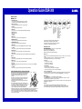
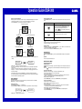
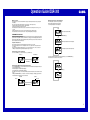
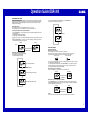
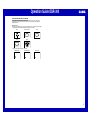
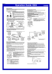
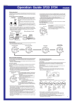
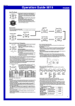
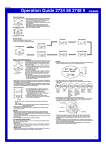
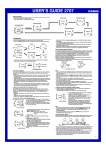
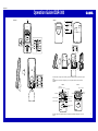
MA0308-EA
Operation Guide DQR-300
1
Main unit
Sub-unit
F
SELECT
°C/ °F
RESET
TEST
C
CASIO
D
SELECT
°C/ °F
RESET
TEST
E
5
SNZ
ON
OFF
ALM
SNZ
ON
OFF
ALM
HUMIDITY
MAX/MIN
TEMP.
MAX/MIN
CLEAR
SET
UP(
+)
DOWN(—)
8
3
2
A
B
HUMIDITY
MAX/MIN
TEMP.
MAX/MIN
CLEAR
SET
+)
UP(
DOWN(—)
RE-SYNC
WAVE
SELECT
°C/ °F
WAVE
RE-SYNC
°C/ °F
SELECT
7
9
RESET
4
0
6
RESET
SELECT
°C/ °F
SELECT
°C/ °F
RESET
TEST
RESET
TEST
¡
™
• A sticker is affixed to the glass of this clock when you purchase it. Be sure to remove the sticker before using the
clock.
• Depending on the clock model, the configuration of your clock may differ somewhat from that shown in the
illustration.
Alarm Off
¡
Current time
(Hour, minutes, seconds)
™
Alarm On
Snooze on indicator
Day of the week
PM indicator
Alarm time
DATE (month - date)
Wave OK indicator
Current Temperature
Current Humidity
Alarm on
indicator
Antenna Icon
Upcomimg weather
indicator
• In locations subject to radio frequency interference, the product may malfunction and require you to reset the
product.
1
Operation Guide DQR-300
GENERAL GUIDE
Main unit
1 SNOOZE/LIGHT button
• Press this button to illuminate the display for about four seconds.
• Pressing this button while the alarm is sounding stops the alarm.
2 Alarm Time Set buttons
Use these buttons to change the alarm time or current time setting.
3 SET button
Use this button when setting the current time.
4 WAVE button
Press this button to receive the time calibration signal and adjust timekeeping.
Inside, among
buildings, or near
neon signs
Inside a vehicle
5 Alarm Mode selector
SNZ: Snooze alarm on
ON: Alarm on
OFF: Alarm off
Near refrigerators
or other household
appliances, near
office equipment,
mobile phones or
wireless LAN
devices.
6 RESET button
Press this button to reset the clock after replacing its batteries.
7 MAX/MIN TEMP. button
Press this button to display the high and low temperature values.
8 MAX/MIN HUMIDITY button
Press this button to display the high and low humidity values.
9 CLEAR button
Press this button to clear the currently displayed high/low temperature or humidity.
0 °C/ °F button
Press this button to toggle the temperature units between Celsius and Fahrenheit.
•
•
•
•
Near a
construction site,
airport, or other
sources of
electrical noise,
underground or in
tunnels, near
railroads,
highways, or radio
stations with
interfering
frequencies.
USING THE CLOCK
Any of the following procedures can be used to set current date and time.
• Auto receive of the time calibration signal
• Manual receive of the time calibration signal
• Manual setting without using the time calibration signal
B SELECT button
Press this button to toggle the display between main unit (INDOOR) and sub-unit (OUTDOOR) data.
Auto Receive
C SELECT button
Press this button to toggle the display between the current temperature and humidity.
D RESET button
Press this button to reset the sub-unit after replacing its batteries.
E TEST button
This button is for testing the unit. Normally, you should not press it. If you do, be sure to press the RESET
button (D) next.
F °C/ °F button
Press this button to toggle the temperature units between Celsius and Fahrenheit.
TIME CALIBRATION SIGNAL RECEPTION PRECAUTIONS
Mainflingen
1200 km
• This clock is able to receive the time calibration signal transmitted from
Mainflingen, Germany (located 25kilometers southeast of Frankfurt).
Signal reception is possible within approximately 1,200 km of the
transmitter.
• Even when the clock is within the reception range, signal reception is
impossible if the signal is blocked by mountains or other geological
formations between the clock and signal source.
• Signal reception is affected by weather, atmospheric conditions, and
seasonal changes.
• The time calibration signal is bounced off the ionosphere. Because of
this, such factors as changes in the reflectivity of the ionosphere, as well
as movement of the ionosphere to higher altitudes due to seasonal
atmosaheric changes or the time of day may change the reception
500 km
range of the signal and make reception temporarily impossible.
• Reception is best when the back of the clock is facing toward Mainflingen. Note, however, that moving the clock
while the time calibration signal receive operation is taking place will make stable reception impossible.
• Think of the clock as acting like a TV or radio when it is receiving the calibration signal.When receiving indoors,
move to a location as near as possible to a window. Proper signal reception can be difficult or even impossible
under the conditions listed below.
Among or behind
mountains
Signal reception is normally better at night than during the day.
Radio interference can make signal reception impossible.
Strong electrostatic charge can result in the wrong time being set.
The alarm does not operate during signal reception.
A RE-SYNC button
Press this button to re-synchronize the timing of the main unit and the sub-unit.
Sub-unit
Near high-tension
power lines
• The clock receives the time calibration signal eight times each day (2:00, 5:00, 8:00, 11:00, 14:00, 17:00, 20:00,
23:00).
• A signal receive operation takes from two to ten minutes under good signal conditions.
• A receive indicator shows the current status of the receive operation.
Antenna Icon
Receive in progress: Icon flashes
Receive failed: Icon not displayed
Receive successful: Icon displayed
Wave OK Indicator
Receive in Progress: OK not displayed
All receives over the past 24 hours failed: OK not displayed
At least one successful receive over the past 24 hours: OK displayed
Unsuccessful Signal Reception
The antenna icon disappears from the display when a signal receive operation is unsuccessful. If this happens,
try changing the position or orientation of the clock, and press the WAVE button (4) to receive again.
Manual Receive
• Press the WAVE button (4) to start a calibration signal receive operation.
• Use the WAVE button (4) to perform a receive operation after replacing the clock’s batteries or if the auto
receive operation was not performed correctly for some reason.
• The clock beeps and display illumination flashes for about three seconds when a receive operation trigged by the
WAVE button (4) is successful.
Important!
• Do not perform any button or switch operation while a signal receive operation is in progress.
• The time calibration signal includes both Standard Time and Daylight Saving Time (summer time) data.
• The DST indicator appears on the display when Daylight Saving Time (summer time) data is received.
2
Operation Guide DQR-300
Turning the Alarm On and Off
Setting the Time and Date Manually
• When using the clock in an area that is outside of the range of the transmitter in Mainflingen or in an area where
signal reception is impossible for some reason, you need to manually adjust the time as required.
1. Press the SET button (3) to cycle through the setting screens as shown below.
Use the Alarm Mode selector (5) on the side of the clock to turn the alarm on and off, and to select the snooze
feature.
Alarm Mode selector
Normal Timekeeping Screen
SNZ
(
)
Description
The alarm sounds at the preset time for one minute, and seven
more times every five minutes thereafter. Even if you stop the
alarm sound by pressing the SNOOZE/LIGHT button (1), the
alarm operation is performed again five minutes later.
• The indicator
flashes on the display to indicate that the
snooze feature is activated.
ALM ON
Year Setting Screen
(
12-hour/24-hour Timekeeping Screen
)
ALM OFF
The alarm sounds at the preset time for one minute.
The alarm does not sound.
• The alarm time appears in place of the date on the display whenever the Alarm Mode selector (5) is set to ON
or SNZ.
• The light also turns on for the first four seconds that the alarm sounds.
• The alarm sound changes over four levels as it sounds.
Stopping the Alarm
Month and Day Setting Screen
Time Setting Screen
• When alarm is sounding, press the SNOOZE/LIGHT button (1) to stop it. When the snooze feature is turned
on, the alarm will sound again in about five minutes.
• To turn off the snooze feature, slide the Alarm Mode selector (5) to OFF.
USING THE LIGHT
Pressing the SNOOZE/LIGHT button (1) turns on the light and illuminates the display for easy reading in the
dark.
2. While the screen you want is on the display, use the Alarm Time Set buttons (2) to change the digits that are
flashing.
Press + to increase
the flashing digits.
+)
UP(
DOWN(—)
Press — to decrease
the flashing digits.
Important!
• Overuse of the light can shorten battery life.
BATTERY REPLACEMENT
Low Battery Warning
• Holding down + or – changes the flashing digits at high speed.
• You can set the year in the range of 2000 to 2039. The day of the week is set automatically in accordance with
the date setting.
• Pressing + or – while the Time Setting Screen is on the display causes the seconds count to be reset to 00.
• Each press of + or – while the 12-hour/24-hour Timekeeping Screen is on the display toggles between 12-hour
and 24-hour timekeeping.
3. After making the settings you want, use the SET button (3) to display the Normal Timekeeping Screen.
• The clock automatically returns to the Normal Timekeeping Screen if you leave a setting screen on the display for
about three minutes without performing any operation.
USING THE ALARM
The alarm sounds and the light turns on when the alarm time you set is reached. You can also use the Alarm
Mode selector (5) to select the snooze alarm feature.
Setting the Alarm Time
Use the Alarm Time Set buttons (2) to set the alarm time.
Pressing the Alarm Time Set buttons (2) causes the alarm time to appear in place of the date on the display.
Press to change the
alarm time setting (+)
+)
UP(
• Holding down + or – changes the digits at high speed.
DOWN(—)
Press to change the
alarm time setting (—)
A
indicator appears on the display to let you know when battery power is low. Replace the batteries as soon
as possible.
Note that the
indicator appears on both the main unit and sub-unit when sub-unit battery power goes low.
To replace main unit batteries
Replace batteries whenever the display of the clock becomes dim and difficult to read.
1. Open the battery compartment cover as shown in the illustration.
2. Remove all of the old batteries.
3. Load a full set of new batteries. Make sure that their positive (+) and negative (–) ends face in the correct
directions. If you load batteries incorrectly, they can burst and damage the clock.
4. Replace the battery compartment cover.
5. Press the RESET button (6). Be sure to press the RESET button (6) after replacing batteries.
To replace sub-unit batteries
1. Open the stand so you can see the back cover.
2. Remove the back cover screw, and then open the back cover.
3. Remove both old batteries.
4. Load new batteries. Make sure that their positive (+) and negative (–) ends face in the correct directions.
If you load batteries incorrectly, they can burst and damage the product.
5. Replace the back cover and secure it in place with the screw.
6. Press the RESET button (D). Be sure to press the RESET button (D) after replacing batteries.
7. Press the RE-SYNC button (A).
3
Operation Guide DQR-300
Battery precautions
• Keep batteries out of the reach of small children. If a battery is accidentally swallowed, contact your physician
immediately.
• Be sure to load the batteries with their positive (+) and negative (–) ends facing correctly.
• Never mix old and new batteries, or batteries of different brands.
• Never charge the batteries that come with the clock.
• Should batteries ever leak while in the clock, wipe out the fluid with a cloth, taking care not to let any get onto
your skin.
• Replace the batteries at least once a year, even if the current batteries are working properly.
• The batteries that come with the clock lose some of their power during transport and storage.
High Temperature and Low Temperature Memory
• The following data is stored in memory automatically.
Main unit high temperature and low temperature
Sub-unit high temperature and low temperature
Current temperature and humidity
THERMOMETER FUNCTIONS
Both the main unit and the sub-unit are equipped with their own temperature sensors. Temperature data measured
by the sub-unit is sent by wireless transfer to the main unit. You can toggle the main unit display between the main
unit temperature reading and the sub-unit temperature reading. This makes it possible to view both the indoor and
outdoor temperature on the main unit display.
MAX/MIN TEMP. button (7)
Main unit high temperature and low temperature
Temperature Measurements
• Both the main unit and the sub-unit take temperature measurements every 16 seconds.
• The temperature display shows “LO” for temperatures below –50°C (–58°F) and “HI” for temperatures above
70°C (158°F).
• Though temperature readings are displayed up to 0°C (32°F) and greater than 41°C (105°F), note that such
readings are actually outside the guaranteed temperature range of this clock.
Sub-unit high temperature and low temperature
Switching between Celsius and Fahrenheit
• Push the °C/ °F button (0) to select either Celsius (°C) or Fahrenheit (°F).
Celsius (°C)
Fahrenheit (°F)
• To clear the high temperature and low temperature data memory, press the CLEAR button (9).
New data starts to be stored after memory is cleared.
°C/ °F button (0)
°F
°C
Switching between Main Unit and Sub-unit Temperature Data
• Press the SELECT button (B) to toggle the display between the main unit (INDOOR) temperature and the subunit (OUTDOOR) temperature.
Main unit temperature: INDOOR indicator displayed
Sub-unit temperature: OUTDOOR indicator displayed
• The display does not change to the sub-unit (OUTDOOR) temperature if no data has been received from the subunit yet.
• Holding down SELECT button (B) for about two seconds causes the display to continually toggle between the
main unit and sub-unit temperature at five-second intervals.
Main unit
CLEAR button (9)
Sub-unit
INDOOR
OUTDOOR
SELECT button (B)
4
Operation Guide DQR-300
HYGROMETER FUNCTIONS
Both the main unit and the sub-unit are equipped with their own humidity sensors. Humidity data measured by the
sub-unit is sent by wireless transfer to the main unit. You can toggle the main unit display between the main unit
humidity reading and the sub-unit humidity reading. This makes it possible to view both the indoor and outdoor
humidity on the main unit display.
• To clear the high humidity and low humidity data memory, press the CLEAR button (9).
New data starts to be stored after memory is cleared.
Humidity Measurements
• Both the main unit and the sub-unit take humidity measurements every 16 seconds.
• The humidity display shows “LO” for humidity below 10% and “HI” for humidity above 90%.
Switching between Main Unit and Sub-unit Humidity Data
• Press the SELECT button (B) to toggle the display between the main unit (INDOOR) humidity and the sub-unit
(OUTDOOR) humidity .
Main unit humidity: INDOOR indicator displayed
Sub-unit humidity: OUTDOOR indicator displayed
• The display does not change to the sub-unit (OUTDOOR) humidity if no data has been received from the sub-unit
yet.
• Holding down SELECT button (B) for about two seconds causes the display to continually toggle between the
main unit and sub-unit humidity at five-second intervals.
Main unit
CLEAR button (9)
Sub-unit
INDOOR
OUTDOOR
USING THE SUB-UNIT
SELECT button (B)
High Humidity and Low Humidity Memory
• The following data is stored in memory automatically.
Main unit high humidity and low humidity
Sub-unit high humidity and low humidity
Current temperature and humidity
MAX/MIN HUMIDITY button (8)
Data Transfer from the Sub-unit
• Data is transferred from the sub-unit to the main unit every three minutes.
• The sub-unit is able to send data to the main unit up to an unobstructed distance of about 30 meters.
• The data receive status is indicated on the display of the main unit by the icons shown below.
Receive successful
Receive unsuccessful
• If a receive operation is not successful for some reason, the display of the main unit shows dashes (–) in place of
the sub-unit temperature and humidity values.
• If you experrience problems with data transfer, press the RE-SYNC button (A) to synchronize the two units.If
this does not eliminate the problem,try changing the positions or orientations of the main unit and sub-unit.
• The transferred data includes temperature and humidity data.
Switching between Celsius and Fahrenheit
• Push the °C/ °F button (F) to toggle between Celsius (°C) and Fahrenheit (°F).
Celsius (°C)
Main unit high humidity and low humidity
Fahrenheit (°F)
°C/ °F button (F)
Switching between Current Temperature and Humidity
Sub-unit high humidity and low humidity
• Press the SELECT button (C) to toggle the display between the current temperature and current humidity.
• Holding down SELECT button (C) for about two seconds causes the display to continually toggle between the
temperature and humidity at five-second intervals.
Temperature
Humidity
SELECT button (C)
Location
• Place the sub-unit in a location where it will not be exposed to rain, direct sunlight, or other elements.
5
Operation Guide DQR-300
USING THE WEATHER FORECAST FEATURE
A built in pressure sensor makes it possible to forecast upcoming weather over the next 12 hours based on
changes in barometric pressure. Note that these forecasts are not absolutely accurate, and are intended for
general reference only.
Weather Forecasts
• Barometric pressure readings are taken every 15 minutes. Weather forecasts are based on the last six readings.
Upcoming weather forecasts are displayed using the graphic indicators shown below.
Sunny
Sunny, some clouds
Rain
Stormy
Cloudy
• Upcoming weather trends are indicated as shown below.
Improving weather
Deteriorating weather
Stable weather
6