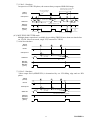
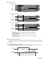
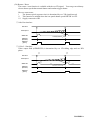
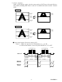
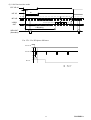
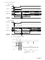
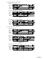
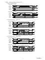
1
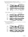
B/W CCD Camera Model CS8560D Specifications (Ver.1.0) 1. 2. 3. 4. 5. 6. 7. 8. Contents Product Description ························· 6 Features·············································· 6 Configuration ···································· 7 Option Unit········································ 7 Operation Mode································ 7 Specifications····································· 24 Timing Chart····································· 32 External View Drawing ··················· 40 D4130891A Important Safety Precautions BEFORE USE - GENERAL SAFETY INSTRUCTIONS This specifications contains important information for the operator (user) and/or people in the vicinity to avoid personal injury, or property damage. • Prior to use, read this specifications carefully to fully understand its instructions for correct use. • After reading, keep operation manual near the equipment for future reference. WARNINGS & CAUTIONS Indication Meaning This indicates the existence of a hazard that death or catastrophic bodily WARNING injury(*1) may result from improper use. CAUTION This indicates the existence of a hazard that bodily injury(*2) or property damage(*3) may result from improper use. Notes *1 Catastrophic bodily injury means loss of eyesight, burns (high and low temperatured), shock, fracture, poisoning, etc. which leaves a sequela and repuire hospitalization or prolonged treatment. *2 Bodily injury means injuries, burns and electric shock which does not require hospitalization or prolonged treatment. *3 Property damage means extended harm to home, household effects, domesticated animals, and pets. Graphic symbol definitions Indication Meaning This mark indicates a prohibited action that must not be carried out. The actual prohibited action is indicated in the symbol or nearby graphically or described in text. This mark indicates a mandatory action that must not be carried out. The actual instruction is indicated in the symbol or nearby graphically or described in text. ●Handling Precautions WARNING Stop operation immediately when any abnormality or defect occurs. Use during an abnormal condition; such as emitting smoke, burning odors, damage from dropping invasion of foreign objects, etc. may cause fire and/or electric shock. Be always sure to disconnect the power plug from the electrical outlet (socket) at once and contact your dealer. Do not operate in places with possibility of becoming wet. This may cause fire and/or electric shock. Do not repair, disassemble and/or modify by yourself. This may cause fire and/or electric shock. Be always sure to contact your dealer for internal repair, check and cleaning of the product. 2 D4130891A Don’t place things or materials on the unit. Ingress of foreign materials such as metallic things and liquid into the unit may cause a fire or an electric shock. Do not put the product in an unstable, slanting and/or vibrated place. Drop and/or fail of the product may cause injury. Do not touch the power cord or other connection cables during a thunderstorm. This might cause electric shock. Use the specified power supply. Use of an unspecified power supply may result in fire or electric shock. Do not be handled roughly, damaged, fabricated, bent forcefully, pulled, twisted, bundled, placed under heavy objects or heated the power cord , connection cable. Otherwise, fire or electric shock may result. CAUTION Note the following instructions when installing. -Do not wrap the product in an inflammable material, such as cloth. -Do not put the product in a narrow space, since the heat generated from the product may be difficult to emanate. If you do not follow the above, the heat generated by the product may cause fire. Avoid setting in humid, smoky, vaporized or dusty places. A fire or an electric shock may occur in such places. This may cause fire and/or electric shock. Do not put the product in direct sunshine and/or high temperature. The temperature inside the product may cause fire. Use the specified DC power cable or connection cable. Otherwise, a fire or an electric shock may occur. Turn OFF the power in the case of connection. Turn OFF the power in the case of connection of power cable or connection cable. Otherwise, an electric shock or a malfunction may occur. Do not expose its camera head to any intensive light (such as direct sunlight). Otherwise, its inner image pickup device might get damaged. Avoid short-circuiting signal output. Otherwise, a malfunction may occur. Avoid giving a strong shock against the camera body. It might cause a breakdown or damage. If your camera is used in a system where its camera connector is subjected to strong repetitive shocks, its camera connector is possible to break down. If you intend to use your camera in such a situation, if possible, bundle and fix a camera cable in the place near the camera, and do not transmit a shock to the camera connector. Ask your dealer to perfom a periodical check and internal cleaning (approx. once every five years). Dust inside the product may cause fire and/or trouble. For check and cleaning cost, please consult your dealer. 3 D4130891A DISCLAIMER (LIMITED WARRANTY) We disclaim any responsibility and shall be held harmless for any damages or losses incurred by the user in any of the following cases; z Fire, earthquake or any other act of God; acts by third parties; misuse by the user, whether intentional or accidental; use under extreme operating conditions. z Malfunction or non-function resulting in indirect, additional or consequential damages, including but not limited to loss of expected income and suspension of business activities. z Incorrent use not in compliance with instructions in this instruction specifications and manual. z Malfunctions resulting from misconnection to other equipment. z Repairs or modifications made by the user or caused to be made by the user and carried out by an unauthorized third party. z Notwithstanding the foregoing, Teli’s liabilities shall not, in any circumstances, exceed the purchase price of the product. z About the item which does not have a publication in the specifications and manual of this product, it considers as the outside for a guarantee. RESTRICTION FOR USE z Should the equipment be used in the following conditions or environments, give consideration to safelty measures and inform us of such usage: 1. Use of the equipment in the conditions or environment contrary to those specified, or use outdoors. 2. Use of the equipment in applications sxpected to cause potential hazard to people or propety, which require special safety measures to be adopted. z This product can be used under diverse operating conditions. Determination of applicability of equipment or devices concerned shall be determined after analysis or testing as necessary by the designner of such equipment or devices, or personnel related to the specifications. Such designer or personnel shall assure the performance and safety of the equipment or devices. z This product is not designed or manufactured to be used for control of equipment directly concerned with human life (*1) or equipment relating to maintenance of of public services/functions involving factors of safety (*2). Therefore, the product shall not be used for such applications. (*1): Equipment directly concerned with human life refers to. - Medical equipment such as life-support systems, equipment for prerating theaters. - Exhaust control equipment for exhaust gases such as toxic fumes or smoke. - Equipment mandatory to be installed by various laws and regulations such as the Fire Act or Building Standard Law - Equipment related to the above. (*2) : Equipment relating to maintenance of public services/functions involving factors of safety refers to. - Traffic control systems for air transportations, railways, roads, or marine transportation - Equipment for nuclear power generation - Equipment related to the above 4 D4130891A CAUTIONS ON USE z Carefully handle the units. Do not drop, or give a strong shock or vibration to the camera. This may cause problems. Treat the camera cables carefully to prevent cable problems, such as cable breakdown and loosened connections. z Operating ambient temperature and humidity. Do not use the camera in places where temperature and humidity exceed the specifications. Picture quality will lower and internal parts may be damaged. Be particularly careful when using in places exposed to direct sunlight. When shooting in hot places, depending on the conditions of the object and the camera (for example when the gain is increased), noise in the form of vertical strips or white dots may occur. This is not a malfunction. z Restriction for the lens combination This camera might form a ghost to image area depending on the combination of a lens and an illumination with this camera. But this is not a failure of this camera. Therefore, please check the combination of the lens and the illumination with this camera when use. When mounting a lens, take extra caution so that the lens is not tilted, nor does flaw exist at the lens-mount-screw part. Also check to confirm that no dirt nor other foreign object is put inside Improper mounting might cause the parts to become locked. z Do not shoot under intense light. Avoid intense light such as spot light on part of the screen because it may cause blooming or smears. If intense light falls on the screen, vertical stripes may appear on the screen, but this is not a malfunction. z Do not expose the camera’s image-pickup-plane to sunlight or other intense light directly. Its inner CCD (charge-coupled device) might be damaged. z Moire When thin stripe patterns are shot, stripe patterns that are not actually there (moire) may appears as interference stripes. This is not a malfunction. z Undesirable noise If the camera or the cables are located near something which emit strong magnetism or near something which emit strong electric wave, undesirable noise may appear on the screen. In such a case, try to change the location of the camera or the cable wiring. z Handling of the protection cap When the camera is not in use, put a lens-cap onto the camera head for protection of the image-pickup-plane. z When not using the camera for a longtime. Stop supplying power for safety. z When cleaning the camera Always turn off the power and clean with a piece of soft dry cloth. To remove stubborn stains, use a soft cloth soaked in diluted acid-free detergent. Do not use alcohol, benzine, thinner, etc. If used, coating and printed letters may be discolored. In case the image-pickup-plane should be settled with fine dust, dirt, or scratched, ask your dealer for technical advice. z Wastes of this product should be separated and discarded in compliance with the various national and local ordinances. 5 D4130891A 1. PRODUCT DESCRIPTION Model CS8560D is an integrated type B/W CCD camera with a VGA format all-pixel-data readout CCD. This model has twice greater driving frequency of conventional cameras to achieve fast-speed data-processing. The model is suited for high-speed, high-resolution image processing use. Its compact, light-weight body is ideal for system integration. 2. FEATURES (1) Double-speed scan This model reads out image-data twice as fast as conventional cameras do. (2) All pixel's data readout With its built-in all-pixel-data-readout CCD, this model can read out image-data just in approximately 1/60 sec. A frame-shutter reads out all data even under RTS (Random Trigger Shutter) mode. (3) High vertical resolution As all pixel's data are read out even under RTS mode (in 1/60 sec.), images with no deterioration in vertical resolution are obtained. (4) Square grid pattern CCD Pixel's in CCD are aligned in square grid pattern. This makes it easier to perform computation correctly for image processing use. (5) External Sync. The camera is switched over to external synchronization operation automatically when external HD signal is input. (6) Random trigger shutter function With a built-in RTS, the camera’s CCD starts light-exposure in synchronization with external trigger signals. This function enables the camera to capture fast-moving subjects at constant position for precise image processing. (7) Restart / Reset Under the restart / reset mode, this model can capture images at an arbitrary timing cued by external VD signal. (8) Multiple shutter With this shutter, this model capture images at an arbitrary timing cued by external trigger signal, and then outputs video at an arbitrary timing cued by external VD signal. (9) Partial-scan Under the partial scan mode, only 1/2 or 1/4 screen center portion of image information is read out, resulting in a faster operation. (10) Ultra-compact & light-weight camera head The model features its ultra-compact and light-weight camera head, freeing you from your integration-space-problem. In addition, it has an excellent shock and vibration resistance. 6 D4130891A 3. CONFIGURATION (1) Camera body··································································· 1 (2) Accessory Operation Manual(Japanese) ··········································· 1 Operation Manual(English) ············································· 1 4. OPTION UNIT (1) DC SYNC IN cable ············ Model name : CPRC3700 [2m,3m,5m,10m] (2) Camera adapter ·················· Model name : CA170 (3) Camera-mounting kit ··········· Model name : CPT8560 (4) Camera-connector fixing hardware *Contact your dealer / distributor for details of option units. *Conformity of an option part and EMC conditions About the conformity of EMC standard of this machine, it has guaranteed in the conditions combined with the above-mentioned option part. When used combined parts other than specification of our company, I ask you to have final EMC conformity checked of a visitor with a machine and the whole equipment. 5. OPERATION MODE (1) GAIN selection (Camera rear-panel SW) Switches sensitivity setting (1-1) FIX ------------------- Factory-prefixed gain (1-2) MANU--------------- Gain is adjustable via the manual gain potentiometer (M.GAIN) (2) Video output mode selection (Camera rear-panel DIP SW) Switches video format (2-1) 1/60: 1/60s ---------- Non-interlace mode As all pixels are read out in 1/60s, you will get images with the higher V resolution. (2-2) 1/120: 1/120s ------- 2:1 interlace MIX mode As vertical pixels are added in readout, the sensitivity is same as that of 1/60s non-interlace mode during electronic shutter OFF. Twice greater sensitivity is obtained under shutter-speed range of 1/200 – 1/20000. (3) RTS (Random Trigger Shutter) exposure selection (Camera rear-panel DIP SW) Switches light exposure mode under RTS mode (3-1) FIX mode ----------- Rear DIP SW Exposure-time control via rear-panel DIP switch (3-2) PULSE W mode---- TRIG signal pulse width control Exposure-time control via TRIG signal pulse width 7 D4130891A (4) Shutter mode selection (Camera rear-panel DIP SW or TRIG signal IN [Automatic]) Switches shutter mode (4-1) NOR mode ---------- Normal electronic shutter Exposure control via internal sync signal High-speed shutter: From 1/20,000s through OFF (8 position) (4-2) RTS mode----------- Random trigger shutter Exposure control via ext. trigger or ext. sync input Timing charts are shown below. (TRIG timing: Positive) Notes: * RTS selection is automatic with TRIG status ** Neither under FIX nor PULSE W mode, RTS doesn’t work if Electronic shutter speed SW is set in OFF position. (a)Non-reset mode (Under internal sync / external sync --- Consecutive VD IN) Exposure starts at the timing of TRIG signal IN. After each exposure is completed, the camera outputs video at each next VD IN timing. □1/60s Non-interlace Automatically returns to normal shutter if fixed H level (after approx. 1/6s) TRIG IN not acceptable for 1V after mode chenge TRIG IN (Positive) INT/EXT VD CCD Exposure Exposure time (E-shutter speed or pulse width) VIDEO OUT Definite Outputs VD,V-SYNC during standby Outputs video at the next VD timing after exposure WEN OUT (Standard) WEN OUT [Option] Normal shutter Random trigger shutter Normal shutter □1/120s 2:1 Interlace Automatically returns to normal shutter if fixed H level (after approx. 1/6s) TRIG IN not acceptable for 1V after mode chenge TRIG IN (Positive) INT/EXT VD EVEN ODD EVEN ODD EVEN ODD EVEN ODD EVEN ODD EVEN ODD EVEN CCD Exposure Exposure time EVEN image VIDEO OUT EVEN ODD (E-shutter speed or image ODD EVEN Outputs VD,V-SYNC during standby WEN OUT (Standard) ODD image pulse width) ODD EVEN ODD EVEN image EVEN Outputs video at the next VD timing after exposure ODD EVEN Definite WEN OUT [Option] Random trigger shutter Normal shutter 8 Normal shutter D4130891A (b) Non-reset mode (Under external sync --- Single VD IN) After TRIG IN and exposure, the camera goes into standby until next ext. VD IN. □1/60s Non-interlace Automatically returns to normal shutter if fixed H level (after approx. 1/6s) TRIG IN not acceptable for 1V after mode chenge TRIG IN (Positive) EXT VD CCD Exposure Exposure time (E-shutter speed or pulse width) VIDEO OUT Definite In sync with ext.VD during standby (No video output) Outputs video at the next VD timing after exposure WEN OUT (Standard) WEN OUT [Option] Normal shutter Random trigger shutter Normal shutter *Don’t provide ext. VD IN during exposure. ** After automatic return, fix ext. VD IN at Hi. □1/120s 2:1 Interlace Video output field (ODD/EVEN) is determined by ext. VD falling edge and ext. HD phase. Automatically returns to normal shutter if fixed H level (after approx. 1/6s) TRIG IN not acceptable for 1V after mode chenge TRIG IN (Positive) ODD phase EXT VD ODD EVEN phase ODD phase EVEN EVEN ODD EVEN ODD CCD Exposure Exposure time (E-shutter speed or pulse width) VIDEO OUT ODD WEN OUT (Standard) ODD EVEN In sync with ext.VD during standby (No video output) EVEN image EVEN ODD image ODD Definite Outputs video at the next VD timing after exposure WEN OUT [Option] Normal shutter Random trigger shutter Normal shutter *Don’t provide ext. VD IN during exposure. ** After automatic return, fix ext. VD IN at Hi. 9 D4130891A (c)V-reset mode (Under internal sync / external sync --- No VD IN) Exposure starts at the timing of TRIG signal IN. After each exposure is completed, the camera outputs video immediately by resetting VD. (HD is not reset) □1/60s Non-interlace Automatically returns to normal shutter if fixed H level (after approx. 1/6s) TRIG IN not acceptable for 1V after mode chenge TRIG IN (Positive) CCD Exposure Exposure time (E-shutter speed or pulse width) VIDEO OUT VD,V-SYNC pause during standby Definite VD,V-SYNC output for 1V only WEN OUT (Standard) WEN OUT [Option] Normal shutter Random trigger shutter Normal shutter □1/120s 2:1 Interlace Irrespective of TRIG IN phase, the camera always outputs ODD field image. Automatically returns to normal shutter if fixed H level (after approx. 1/6s) TRIG IN not acceptable for 1V after mode chenge TRIG IN (Positive) CCD Exposure ODD image VIDEO OUT ODD EVEN image Exposure time (E-shutter speed or pulse width) EVEN ODD image ODD ODD image ODD Definite VD,V-SYNC pause during standby VD,V-SYNC output for 1V only WEN OUT (Standard) WEN OUT [Option] Normal shutter Random trigger shutter Normal shutter (d) SYNC reset mode (Under internal sync) Exposure starts at TRIG signal input timing, resets HD, and outputs video immediately after exposure by resetting VD. * Available under FIX mode only. □1/60s Non-interlace Automatically returns to normal shutter if fixed H level (after approx. 1/6s) TRIG IN not acceptable for 1V after mode chenge TRIG IN (Positive) CCD Exposure Exposure time (E-shutter speed) VIDEO OUT Definite VD,V-SYNC pause during standby VD,V-SYNC output for 1V only WEN OUT (Standard) WEN OUT [Option] Normal shutter Random trigger shutter 10 Normal shutter D4130891A □1/120s 2:1 Interlace Irrespective of TRIG IN phase, the camera always outputs ODD field image. Automatically returns to normal shutter if fixed H level (after approx. 1/6s) TRIG IN not acceptable for 1V after mode chenge TRIG IN (Positive) CCD Exposure ODD image VIDEO OUT ODD EVEN image Exposure time (E-shutter speed) EVEN ODD image ODD VD,V-SYNC pause during standby ODD image ODD Definite VD,V-SYNC output for 1V only WEN OUT (Standard) WEN OUT [Option] Normal shutter Random trigger shutter Normal shutter (4-3) MULTIPLE SHUTTER mode Multiple shutter operation is available by providing TRIG IN more than one time before ext. VD IN. (Non-reset mode, single VD, consecutive VD IN) □1/60s Non-interlace TRIG IN (Positive) EXT VD CCD Exposure Exposure time (E-shutter speed or pulse width) VIDEO OUT Three exposures are mixed and output here WEN OUT (Standard) WEN OUT [Option] □1/120s 2:1 Interlace Video output field (ODD/EVEN) is determined by ext. VD falling edge and ext. HD phase. TRIG IN (Positive) EVEN phase ODD phase EXT VD CCD Exposure ODD image VIDEO OUT Exposure time (E-shutter speed or pulse width) EVEN image Three exposures are mixed and output here WEN OUT (Standard) WEN OUT [Option] 11 D4130891A RTS TRIG IN notes 1/60s Non-interlace 1 2 3 4 5 6 7 8 9 10 11 12 13 14 15 16 17 18 19 20 21 22 23 24 25 510 511 512 513 514 515 516 517 518 519 520 521 9H INT VD INT HD OB 1 2 3 4 5 490 492 494 OB VIDEO OUT WEN OUT (Standard) Video output time TRIG invalid period 1/120s Interlace ODD Field 1 2 3 4 5 6 7 8 9 10 11 12 13 14 15 16 17 18 19 20 21 22 23 24 25 259 260 261 262 263 264 265 266 267 268 269 270 9H INT VD INT HD OB 8 OB 2 4 6 9 1 3 5 7 12 13 16 17 484 488 492 485 489 493 OB VIDEO OUT WEN OUT (Standard) TRIG invalid period Video output time 1/120s Interlace EVEN Field 259 260 261 262 263 264 265 266 267 268 269 270 9H 1 2 3 4 5 6 7 8 9 10 11 12 13 14 15 16 17 18 19 20 21 22 23 24 25 INT VD INT HD OB 7 1 3 5 8 2 4 6 11 12 15 16 483 487 491 484 488 492 OB VIDEO OUT WEN OUT (Standard) TRIG invalid period Video output time * TRIG becomes invalid even if TRIG (exposure start) is inputted during TRIG invalid period. * An image may be affected if TRIG (exposure start) is inputted during the video output time. * An imege may not be outputted normally if exposure is terminated during the video output time. Exposure time delay under RTS When the RTS is active, both in FIX mode and PULSE W mode, there is a time delay of approximately 1.4 micro s until the start of exposure after the rising edge of TRIG signal (positive). Exposure time under pulse width mode Under RTS pulse mode, the exposure time is determined by the pulse width. More exactly, the actual time is the pulse width plus approximately 8.0 micro s. TRIG IN Pulse width CCD Exposure Exposure delay time = Approximately 1.4 micro s Exposure time = Pulse width + Approx. 8.0 micro s 12 D4130891A (5-4) Restart / Reset The restart / reset function is available with the ext.VD signal. You can get an arbitrary slower shutter speed than normal shutter and random trigger shutter. Here are some notes; * The shutter speed (exposure time) is determined by ext. VD signal interval. ** This function is enabled when the rear-panel shutter speed DIP SW is OFF. *** Supply consecutive HD. □1/60s Non-interlace EXT VD IN CCD Exposure VIDEO OUT The exposure time is determined by VD interval WEN OUT (Standard) WEN OUT [Option] □1/120s 2:1 Interlace Video output field (ODD/EVEN) is determined by ext. VD falling edge and ext. HD phase. EVEN phase ODD phase EXT VD IN CCD Exposure ODD image EVEN image VIDEO OUT ODD The exposure time is determined by VD interval EVEN WEN OUT (Standard) WEN OUT [Option] 13 D4130891A (5) Partial-scan mode selection (Camera rear-panel DIP SW) Switches partial-scan mode Note: Sometimes phenomenon called as “whiteout” occurs at the top of the screen when there is strong incident light entering in the wide area of a CCD, however, this is not a malfunction. If this occurs, reduce the amount of incoming rays. (5-1)1/2 Partial-scan (Rear-panel SW: #8-OFF, #9-ON) --- Screen center 1/2 readout □1/60s Non-interlace Under 1/60s non-interlace mode, only the center portion of 227H out of the total effective lines 494H (excluding BLK time) is read out. Available both under external / internal mode. 130H High-speed transfer 227H Normalspeed transfer 137H High-speed transfer Normalspeed transfer 227H ■Under normal shutter (Electronic shutter OFF) Notes: * Under ext. sync, the ext. VD should be 1V = 262H. ** Under normal shutter, set the rear-panel DIP SW #6, #7 in OFF. 131 357 131 357 <V-reset> VIDEO OUT 21H 227H 14H V BLK (Include High-speed transfer) VIDEO output time Highspeed transfer 262H WEN OUT (Standard) WEN OUT [Option] 262H 3H 3H 3H 3H 3H 3H ■Under other shutter modes 131 357 <Non-reset> VIDEO OUT 227H 21H V BLK (Include High-speed transfer) WEN OUT (Standard) VIDEO output time 14H (263H) Highspeed transfer *1 3H 3H WEN OUT [Option] *2 4H *1:Arbitrary under ext.sync *2:See "7.TIMING CHART (4)WEN timing". 14 D4130891A □1/120s 2:1 Interlace Under 1/120s interlace mode, only the center portion of 207H out of the total effective lines 485H (excluding BLK time) is read out. Available both under external / internal mode. ODD Field 73H High-speed trasfer 103H Normalspeed transfer 104H Normalspeed transfer Normalspeed transfer 103H High-speed transfer 66.5H EVEN Field 72.5H High-speed transfer 104H Normalspeed transfer 66H High-speed transfer ■Under normal shutter (Electronic shutter OFF) Notes: * Under ext. sync, the ext. VD should be 1V = 131.5H. ** Under normal shutter, set the rear-panel DIP SW #6, #7 in OFF. 154 155 ODD image 153 154 358 359 EVEN image <V-reset> 359 360 VIDEO OUT 21H V BLK (Include High-speed transfer) 103H VIDEO output time 131.5H 7H 20.5H HighV BLK speed (Include transfer High-speed transfer) 0.5H 104H 7H VIDEO output time Highspeed transfer 131.5H WEN OUT (Standard) 9H 8.5H 9H WEN OUT [Option] 9H 8.5H 9H 15 D4130891A ■Under other shutter modes ODD image 154 155 <Non-reset> 358 359 VIDEO OUT WEN OUT (Standard) 9H WEN OUT [Option] 10H 7H (131.5H) 103H 21H V BLK (Include High-speed transfer) VIDEO output time *1 Highspeed transfer 8.5H *2 EVEN image 153 154 359 360 VIDEO OUT 104H 20.5H WEN OUT (Standard) V BLK (Include High-speed transfer) VIDEO output time 7H (132H) Highspeed transfer *1 8.5H 9H WEN OUT [Option] 9.5H *2 *1:Arbitrary under ext.sync *2:See "7.TIMING CHART (4)WEN timing". 16 D4130891A (5-2)1/4 Partial-scan (Rear-panel SW: #8-ON, #9-ON) --- Screen center 1/4 readout □1/60s Non-interlace Under 1/60s non-interlace mode, only the center portion of 81H out of the total effective lines 494H (excluding BLK time) is read out. Available both under external / internal mode. 81H High-speed transfer 200H Normalspeed transfer Normalspeed transfer 81H High-speed transfer 213H ■Under normal shutter (Electronic shutter OFF) Notes: * Under ext. sync, the ext. VD should be 1V = 131H. ** Under normal shutter, set the rear-panel DIP SW #6, #7 in OFF. 201 281 201 281 <V reset> VIDEO OUT 28H 81H V BLK (Include High-speed transfer) Video output time 22H High -speed transfer 131H WEN OUT (Standard) WEN OUT [Option] 131H 3H 3H 3H 3H 3H 3H ■Under other shutter modes 201 281 <Non-reset> VIDEO OUT 81H 28H V BLK (Include High-speed transfer) Video output time 22H (394H) High -speed transfer *1 WEN OUT (Standard) 3H 3H WEN OUT [Option] 4H *2 *1:Arbitrary under ext.sync *2:See "7.TIMING CHART (4)WEN timing". 17 D4130891A □1/120s 2:1 Interlace Under 1/120s interlace mode, only the center portion of 61H out of the total effective lines 485H (excluding BLK time) is read out. Available both under external / internal mode. ODD Field 103H 30H 109.5H High-speed transfer 30H Normalspeed transfer Normalspeed transfer High-speed transfer EVEN Field 102.5H 31H 109H High-speed transfer 31H Normalspeed transfer Normalspeed transfer High-speed transfer ■Under normal shutter (Electronic shutter OFF) Notes: * Under ext. sync, the ext. VD should be 1V = 65.5H. ** Under normal shutter, set the rear-panel DIP SW #6, #7 in OFF. 214 215 ODD image 272 273 213 214 EVEN image <V reset> 273 274 VIDEO OUT 24H V BLK (Include High-speed transfer) WEN OUT (Standard) WEN OUT [Option] 30H Video output time 65.5H 11H High -speed transfer 0.5H 23.5H V BLK (Include High-speed transfer) 31H Video output time 65.5H 11H High -speed transfer 9H 8.5H 9H 9H 8.5H 9H 18 D4130891A ■Under other shutter modes ODD image 214 215 <Non-reset> 272 273 VIDEO OUT WEN OUT (Standard) 11H (197.5H) 30H 24H V BLK (Include Highspeed transfer) Video output time *1 High -speed transfer 9H 8.5H WEN OUT [Option] 10H *2 EVEN image 213 214 273 274 VIDEO OUT 31H 23.5H V BLK (Include Highspeed transfer) WEN OUT (Standard) Video output time 11H (197H) High -speed transfer *1 8.5H 9H WEN OUT [Option] 9.5H *2 *1:Arbitrary under ext.sync *2:See "7.TIMING CHART (4)WEN timing". 19 D4130891A (5-3) Programmable partial [Option] By designating the high-speed transfer portion with external PARTIAL signal input, the camera read out only the portion of CCD area necessary for your application. This is available under ext. sync. EXT VD EXT HD 1(H) 10 Line 2(H) PARTIAL PULSE a(H) [ *1 ] VIDEO OUT n(H) Total line = n(H) x 10 line Start Finish High-speed trans. n(H) 1/60s non-interlace [*1] a(H) BLK trans. 2(H) 1/120s Interlace 1st field 6.0 Normal-speed 12.0 2nd field 11.5 (Conditions) z The starting point of external partial signal is [*1] from the falling edge of ext. VD. z The external partial signal is controlled at each ext. HD falling edge. Set the start / finish of the external partial signal in 1H increments. z The number of 1H high-speed transfer line is 10 lines. The actual lines are determined by the external partial signal “hi” period. (Minimum: 2H = 20 lines) z Set video output time more than 30H. And high-speed transfer time (the external partial signal “hi” period) before video output time is is as follows; from 2H through 22H under 1/60s non-interlace mode from 2H through 11H under 1/120s interlace mode z After high-speed transfer, 2H is allocated to blank transfer period. Normal transfer starts at the next line. z VIDEO OUT vertical blanking is; V. blanking = [*1](H) + n(H) + BLK transfer [2(H)] – 1H Example follows below. (High-speed 2H = 20 lines (minimum), Normal-speed 70 lines + BLK 2H) Note: Items shown as [Option] in this document is not included in your purchase as standard components. Contact our dealer / distributor for details. 20 D4130891A □1/60s Non-interlace OB 2ライン 10H High-speed transfer 68H Normalspeed transfer 416H 68H Normalspeed transfer High-speed transfer The timing is as follows; EXT.VD 1H 494 1 VIDEO OUT (Normal scan) 20H 494H V BLK WEN OUT (Standard) 3H 70H 2H *2 Partial Pulse 6H 11 78 VIDEO OUT (Partial scan) 9H V BLK 68H VIDEO OUT (448H) *1 WEN OUT (Standard) 3H WEN OUT (Normal shutter mode) [Option] WEN OUT (Other shutter mode) [Option] *3 4H *1:Arbitrary under ext.sync. *2:Partial over actual line is OK. *3:See "7.TIMING CHART (4)WEN Timing". 21 D4130891A □1/120s 2:1 Interlace, ODD field OB 2ライン 13H High-speed transfer 68H Normalspeed transfer 161.5H High-speed transfer 68H Normalspeed transfer The timing is as follows; ODD Feild EXT.VD 1H 8 9 492 493 VIDEO OUT (Normal scan) 20H 242.5H V BLK WEN OUT (Standard) 9H *2 70H 2H Partial Pulse 12H 34 35 168 169 VIDEO OUT (Partil scan) 15H 68H VIDEO OUT V BLK WEN OUT (Standard) (179.5H) *1 9H WEN OUT (Normal shutter mode) [Option] WEN OUT (Other shutter mode) [Option] *3 10H *1:Arbitrary under ext.sync. *2:Partial over actual line is OK. *3:See "7.TIMING CHART (4)WEN Timing" . 22 D4130891A □1/120s 2:1 Interlace, EVEN field OB 2ライン 12.5H High-speed transfer 68H Normalspeed transfer 68H Normalspeed transfer High-speed transfer 162H The timing is as follows; EVEN Feild EXT.VD 1H 7 8 491 492 VIDEO OUT (Normal scan) 20H 242.5H V BLK WEN OUT (Standard) 8.5H *2 70H 2H Partial Pulse 11.5H 33 34 167 168 VIDEO OUT (Partial scan) 14.5H 68H VIDEO OUT V BLK WEN OUT (Standard) (180H) *1 8.5H WEN OUT (Normal shutter mode) [Option] WEN OUT (Other shutter mode) [Option] *3 9.5H *1:Arbitrary under ext.sync. *2:Partial over actual line is OK. *3:See "7.TIMING CHART (4)WEN Timing". Note: Items shown as [Option] in this document is not included in your purchase as standard components. Contact our dealer / distributor for details. 23 D4130891A 6. SPECIFICATIONS [Basic spec] (1) Image sensor Total pixels Active pixel Video output pixels Scanning area Unit cell size (2) TV system (3) Scanning lines (4) Interlace (5) Sync system (6) Aspect ratio (7) Video output (8) Resolution (9) S/N (10) Illumination (11) Gain (12) Gamma correction (13) White-clip level (14) Power source (15) Power consumption [Internal sync spec] (1) Base clock frequency (2) H sync frequency (3) V sync frequency All Pixel’s Data Read-out Interline CCD 692(H) x 504(V) 659(H) x 494(V) 648(H) x 494(V) (Under non-interlace) 4.88(H) x 3.66(V) mm (=Equivalent to 1/3 type CCD size) 7.4(H) x 7.4(V) micro m (Square-grid array) Special format (Non-conforming to EIA) 525 lines 1/60s Non-interlace mode 1/120s 2:1 Interlace mode Switching via rear-panel DIP SW Internal/External automatic switch-over 4:3 VS 1.0V(p-p) / 75Ω, DC coupled, 1 line (AC as [Option]) 485 TV lines(H) 485 lines (350 TV lines)(V) Standard: 52dB(p-p)/rms (Initial factory setting) Standard 400 lx (F5.6) Minimum 4 lx (F1.4) (GAIN MAX, Approx. 50% video output) FIX (Fixed) gain: Factory-shipped preset level MANU (Manual) gain: Setting through GAIN VR FIX / MANU switching via rear-panel DIP SW Gamma = 1 (Fixed) Approx. 840mV(p-p) (Excluding SYNC) DC12V ±10% Ripple voltage: 50mV(p-p) or less Approx. 1.5W 24.545MHz (1CLK) ±200ppm 31.468kHz (1H = 780CLK) 59.94Hz (Under non-interlace) 119.88Hz (Under 2:1 interlace) Note: Items shown as [Option] in this document is not included in your purchase as standard components. Contact our dealer / distributor for details. 24 D4130891A [External sync spec] (1) Ext. sync input signal (2) Input impedance (3) Input level (4) Interlace (5) Polarity (6) Pulse width (7) Repeating frequency (8) Phase difference HD/VD 75-ohm / High impedance 10k-ohm (switching via rear-panel SW) (Initial factory setting: High) From 2 through 5V (p-p) under high impedance input From 2 through 4V (p-p) under 75-ohm input 1/60s non-interlace or 1/120s 2:1 interlace Negative HD: 3.2 +/- 1 micro s (LOW) VD: From 125 through 400 micro s (LOW) fH = 31.468kHz +/- 1% fV = fH/262.5 or fH/525 HD/VD: 0 +/- 5.0 micro s, 1/fH/2 +/- 5.0 micro s Exposure-starting-cue signal in random trigger shutter mode LOW level: From 0 through 0.5V(p-p) HIGH level: From 4 through 5V(p-p) High impedance (10k-ohm) Rising edge detection (Positive) (Falling edge detection (Negative) as [Option]) Minimum 2 micro s Maximum 1/8s [Shutter trigger spec] (1) Input level (2) Input impedance (3) Capture timing (4) Pulse width [Sync signal spec] (1) Readout signal (2) Polarity (3) Pulse width WEN readout timing pulse Negative (Positive under VIDEO output mode [Option]) 1H output (Available under VIDEO output mode [Option]) VIDEO OUT WEN OUT (1H) NEGA WEN OUT (VIDEO output) [Option] (4) Output circuit POSI * Set WEN termination to be high impedance. 5V WEN WEN OUT 100 50 Note: Items shown as [Option] in this document is not included in your purchase as standard components. Contact our dealer / distributor for details. 25 D4130891A [Electronic shutter spec] (1)Normal shutter Shutter-speed setting via rear-panel SW (Initial: OFF) 8 steps switch-able (= OFF, 1/200s, 1/500s, 1/1000s, 1/2000s, 1/4000s, 1/8000s, 1/20000s) (2)RTS (a)Operation mode No. Reset Exposure 1 Rear SW (FIX mode) 2 3 Internal TRIG pulse width (PULSE width mode) 5 6 10 Consecutive HD / Consecutive VD IN Consecutive HD / Single VD IN V-reset 8 9 Consecutive HD / Consecutive VD IN Consecutive HD / Single VD IN Non-reset 4 7 Sync Internal Internal Rear SW (FIX mode) SYNC reset V reset 11 Consecutive HD IN Internal TRIG pulse width (PULSE width mode) Internal Consecutive HD IN Notes : * RTS mode automatically switches over through TRIG IN **RTS disabled under Electronic shutter OFF (b)Multiple shutter Multiple shutter via ext. trigger signal and ext. VD signal Notes : * Operation like No.3, 6 above (3)Restart / Reset Restart / reset available via ext. VD signal (Switching via rear panel DIP SW, Initial OFF) Notes : * The exposure-time (shutter-speed) is determined by ext. VD interval. ** Enabled when rear-panel DIP SW OFF. ***Provide Consecutive HD. [Partial scan] (1)Operation mode No 1 2 3 4 5 6 7 8 9 Scan mode Sync Internal 1/2 partial Consecutive HD VD IN Consecutive HD (VD) IN Internal 1/4 partial Programmable Consecutive HD VD IN Consecutive HD (VD) IN Consecutive HD VD IN Reset Non-reset V-reset Non-reset V-reset Non-reset V-reset Non-reset V-reset Non-reset E-shutter Normal Enabled [Option] Disabled Enabled [Option] Disabled Enabled [Option] Disabled Enabled [Option] Disabled Enabled [Option] E-shutter RTS Enabled Enabled Enabled Enabled Enabled [Option] Note: Items shown as [Option] in this document is not included in your purchase as standard components. Contact our dealer / distributor for details. 26 D4130891A (2) Reset mode As shown in (1) above, non-reset and V-reset is available. ([Option]: Doesn’t come as standard. Contact our dealer / distributor for details) (a) non-reset (Electronic shutter enabled) VD doesn’t get reset after video readout. The interval of VD signal is as follows. 1/60s non-interlace 1/120s interlace 1/2 partial scan 1/4 partial scan 525H 525H 262.5H 262.5H Partial A Partial B Partial C VIDEO OUT VD Interval *Note: Under normal shutter mode, when non-reset is selected on partial scan, electronic shutter is valid. Please note that the exposure time is shortened than the setting value when the external VD is input at shorter than the above VD interval. (b) V-reset (Electronic shutter disabled) VD does get reset after video readout. Under internal sync, the interval of VD signal is as follows. 1/60s non-interlace 1/120s interlace Partial A 1/2 partial scan 1/4 partial scan 262H 131H 131.5H 65.5H Partial B Partial C Partial D Partial E VIDEO OUT VD interval (3) Partial signal [Option] Programmable mode input signal (a) Input level LOW level: From 0 through 0.5V HIGH level: From 4 through 5V (b) Input impedance High impedance (10kΩ) (c) Polarity Positive (Hi: High-speed transfer) Note: Items shown as [Option] in this document is not included in your purchase as standard components. Contact our dealer / distributor for details. 27 D4130891A [Mechanical spec] (1) External dimension (2) Weight (3) Lens mount (4) GND / insulation 29 x 29 x 39.5(D) mm (Not including protrusion) Refer to the attached external view drawing Approximately 42g C mount Circuit GND - Chassis electrically conducted [Ambient condition] (1)Environment condition Performance guaranteed Temperature: From 0 through 40 °C Humidity: From 30 through 90 % (No condensing) Operation guaranteed Temperature: From -5 through 45 °C Humidity: From 10 through 90 % (No condensing) Storage Temperature: From -20 through 60 °C Humidity: From 10 through 90 % (No condensing) (2)EMC conditions (Electro-Magnetic Compatibility) EMI (Electro-Magnetic Interference) EN61000-6-4 Conformity EMS (Electro-Magnetic Susceptibility) EN61000-6-2 Conformity *Conformity of EMC conditions About the conformity of the EMC standard of this machines, it has guaranteed in the conditions combined with the option part of 4th clause. When used combining parts other than specification of our company, I ask you to have final EMC conformity checked of a visitor with a machine and the whole equipment. 28 D4130891A [Connector pin assignment] (1) Compatible connector (2) Pin assignment HR10A-10P-12S (Supplied by HIROSE ELEC.) Connector pin layout ① ② ⑨ ⑪ ③ ⑧ ⑩ ⑫ ④ ⑦ ⑥ ⑤ Picture Rear-panel camera connector (Rear-view) 12 pin male Pin No. 1 2 3 4 5 6 7 8 9 10 11 12 Signal (Standard) DC12V GND DC12V VIDEO GND VIDEO OUT HD GND HD IN VD IN TRIG GND NC WEN OUT TRIG IN VD GND Signal [Option] NC TRIG IN GND DC12V PARTIAL NC Notes : *Before connecting / disconnecting the connector, make sure the camera power is OFF. **For board connection, check compatibility. Note: Items shown as [Option] in this document is not included in your purchase as standard components. Contact our dealer / distributor for details. 29 D4130891A [Switch setting] (1) CCU rear-panel DIP SW No. Function OFF 1 GAIN selection (GAIN) Factory-set GAIN 2 3 4 E-shutter-speed (SHUT) 5 6 7 8 9 0 Video output mode (VIDEO) Shutter mode (SMODE) Partial scan (PART) RTS Exposure (EXP) Notes: ON Manual GAIN adjustable via GAIN GAIN 1 2 SHUT 3 4 VIDEO 5 6 SMODE 7 8 PART 9 EXP 0 See shutter-speed table (Table 1) 1/60s non-interlace 1/120s interlace See shutter-mode table (Table 3) See partial-scan table (Table 2) FIX mode * PULSE W mode Initial factory setting: All OFF (Table 1) Electronic shutter-speed (Table 2) Partial-scan Shutter-speed OFF 1/200s 1/500s 1/1,000s 1/2,000s 1/4,000s 1/8,000s 1/20,000s Partial scan OFF Not acceptable 1/2 partial 1/4 partial No.2 OFF ON OFF ON OFF ON OFF ON O N No.3 OFF OFF ON ON OFF OFF ON ON No.4 OFF OFF OFF OFF ON ON ON ON No.8 No.9 OFF OFF ON OFF OFF ON ON ON Notes : *Don’t set Electronic shutter-speed in OFF under RTS mode. (Table 3) Shutter-mode Shutter mode V reset Random SYNC reset trigger Non-reset Not acceptable Non-reset Random (Multiple shutter) trigger Non-reset V reset Restart / Reset SYNC No.6 No.7 OFF OFF ON OFF OFF ON ON ON Internal sync OFF OFF Single VD ON OFF Consecutive VD OFF ON No VD ON ON Single VD Ext. sync HD IN Notes : * Under normal shutter mode partial-scan, set No.6,7 in OFF. **Under PULSE W mode, SYNC reset is disabled. (2)CCU rear-panel SW Function SW Selected Function Ext. SYNC IN impedance HIGH HIGH impedance (Initial factory setting) (HD/VD) 75Ω 75Ω 30 D4130891A [Relative Spectrum Response] *Including lens characteristics, Excluding light source characteristics [Optical black characteristics] 2 Effective Image Area V 494 504 8 2 659 31 692 H Device structure Total pixels : 692(H) x 504(V) Effective pixels : 659(H) x 494(V) Optical black Horizontal : 2pixels --- 31pixels Vertical : 8pixels --- 2pixels 31 D4130891A 32 WEN OUT CAM VIDEO OUT 78CLK (3.18µs) INT HD EXT HD 6 6 5 5 5 6 6 5 9 O B 1 18CLK (0.73µs) 4CLK ±0.5µs O B 3 1 H. trans. pause 72CLK 60CLK (2.44µs) D O O 1 B B 6 1 2 2CLK 54CLK (2.20µs) Dummy Opt. pixels Blk. D 1 16CLK 1 7CLK Horizontal scan (1H) 780CLK(31.78µs) H. blanking 132CLK(5.38µs) H.SYNC Opt.Blk. 31CLK 7 8 648CLK (26.40µs) V-OUT Effective pixels Effective pixels = 659CLK 648CLK 6 6 5 5 5 6 4CLK 6 5 9 1CLK=40.74ns 7. TIMING CHART (1)H rate timing D4130891A (2) 1/60s Non-interlace mode EXT VD IN 1H delay 6 5 4 3 2 1 525 517 516 515 3 514 23 2 513 22 1 512 21 20 19 18 17 16 15 14 13 12 11 9 10 8 7 6 4 3 2 1 525 524 523 5 9H INT VD INT HD VIDEO OUT OB OB OB OB OB OB OB OB 492 493 494 OB OB V.Blanking WEN OUT (Standard) 20H 1H 1H Ext. VD – Ext. HD phase difference EXT VD IN EXT HD IN TP2 TP1 INT VD TP1 : 10.0 us TP2 : 5.0 us 33 D4130891A (3) 1/120s 2:1 Interlace mode ODD (1st field) EXT VD IN 1H delay 35 10 12 14 16 18 20 22 24 26 28 30 32 34 36 11 13 15 17 19 21 23 25 27 29 31 33 35 37 34 32 8 9 33 31 30 29 28 27 26 25 24 23 20 22 19 282 5 6 21 18 281 3 4 17 280 OB OB OB OB 1 OB OB OB OB 2 16 6 7 15 4 5 14 OB OB OB OB 2 OB OB OB OB 1 3 13 12 11 9 10 8 7 6 4 3 2 1 525 524 523 5 9H INT VD INT HD 487 489 491 488 490 492 VIDEO OUT 493 OB 494 OB V. Blanking 20H 1H WEN OUT (Standard) EVEN (2nd field) EXT VD IN 1H delay 297 296 295 294 293 292 291 290 289 288 287 286 284 285 283 279 278 277 276 275 274 273 272 271 270 269 268 266 265 264 263 262 261 260 267 9H INT VD 7 8 9 11 13 15 17 19 21 23 25 27 29 31 33 35 10 12 14 16 18 20 22 24 26 28 30 32 34 36 INT HD 486 488 490 492 487 489 491 493 VIDEO OUT 494 OB OB V. Blanking 20H 1H WEN OUT (Standard) Ext. VD – Ext. HD phase difference EXT VD IN (1) (2) EXT HD IN TP3 TP3 TP1 (1) INT VD ODD TP2 (2) EVEN INT VD TP1 : ODD reset range TP2 : EVEN reset range TP3 : 5.0 us 34 10.0 us 10.0 us D4130891A (4) WEN timing (a)Normal shutter mode <1/60s Non interlace mode> Under normal scan mode 9H INT VD 494 1 2 OB VIDEO OUT (Normal scan) V.Blanking WEN OUT (Standard) WEN OUT [Option] OB V.Blanking 1H 4H 521H 3H Under partial scan V-reset mode (Standard) 9H INT VD High-speed transfer OB VIDEO OUT (Partial scan) V.Blanking WEN OUT (Standard) WEN OUT [Option] V.Blanking 1H 4H 3H * * 1/2 partial scan : 258H 1/4 partial scan : 127H Under partial scan Non-reset mode [Option] 9H High-speed transfer INT VD OB VIDEO OUT (Partial scan) V.Blanking WEN OUT (Standard) WEN OUT [Option] V.Blanking 1H 4H 521H 35 3H D4130891A <1/120s Interlace mode ODD Field> Under normal scan mode INT VD 9H 8 9 V.Blanking WEN OUT (Standard) WEN OUT [Option] 492 493 OB VIDEO OUT (Normal scan) V.Blanking 1H 10H 252.5H 8.5H Under partial scan V-reset mode (Standard) INT VD VIDEO OUT (Partial scan) 9H High-speed transfer OB V.Blanking V.Blanking WEN OUT (Standard) WEN OUT [Option] 494 OB 1H 10H 8.5H * * 1/2 partial scan : 121.5H 1/4 partial scan : 55.5H Under partial scan Non-reset mode [Option] INT VD VIDEO OUT (Partial scan) 9H High-speed transfer OB V.Blanking WEN OUT (Standard) WEN OUT [Option] 494 OB V.Blanking 1H 10H <1/120s Interlace mode 252.5H 8.5H EVEN Field> Under normal scan mode INT VD VIDEO OUT (Normal scan) 9H 7 8 V.Blanking WEN OUT (Standard) WEN OUT [Option] 491 492 OB OB V.Blanking 1H 9.5H 253H 9H Under partial scan V-reset mode (Standard) INT VD VIDEO OUT (Partial scan) 9H High-speed transfer V.Blanking WEN OUT (Standard) WEN OUT [Option] OB OB V.Blanking 1H 9.5H 9H * * 1/2 partial scan : 122H 1/4 partial scan : 56H Under partial scan Non-reset mode [Option] INT VD VIDEO OUT (Partial scan) 9H High-speed transfer V.Blanking WEN OUT (Standard) WEN OUT [Option] OB OB V.Blanking 1H 9.5H 253H 36 9H D4130891A (b)RTS Non-reset mode (Consecutive VD) <1/60s Non interlace mode> Under normal scan mode 9H INT VD 494 1 2 OB VIDEO OUT (Normal scan) OB V.Blanking WEN OUT (Standard) 1H WEN OUT [Option] 521H 3H 4H Under partial scan mode 9H INT VD High-speed transfer OB VIDEO OUT (Partial scan) V.Blanking V.Blanking WEN OUT (Standard) 1H WEN OUT [Option] 521H 3H 4H <1/120s Interlace mode ODD Field> Under normal scan mode INT VD VIDEO OUT (Normal scan) 9H 8 9 492 493 OB V.Blanking WEN OUT (Standard) V.Blanking 1H WEN OUT [Option] 8.5H 252.5H 10H Under partial scan mode INT VD VIDEO OUT (Partial scan) 9H High-speed transfer OB 494 OB V.Blanking WEN OUT (Standard) V.Blanking 1H WEN OUT [Option] 252.5H 8.5H 10H <1/120s Interlace mode EVEN Field> Under normal scan mode INT VD VIDEO OUT (Normal scan) 9H 7 8 491 492 OB OB V.Blanking WEN OUT (Standard) V.Blanking 1H WEN OUT [Option] 253H 9H 9.5H Under partial scan mode INT VD VIDEO OUT (Partial scan) 9H High-speed transfer OB OB V.Blanking V.Blanking WEN OUT (Standard) 1H WEN OUT [Option] 253H 9H 9.5H 37 D4130891A (c)RTS Non-reset mode (Single VD) / V-reset mode / SYNC-reset mode <1/60s Non interlace mode> Under normal scan mode 9H INT VD 494 1 2 OB VIDEO OUT (Normal scan) OB V.Blanking WEN OUT (Standard) 1H WEN OUT [Option] 521H 3H 4H Under partial scan mode 9H INT VD High-speed transfer OB VIDEO OUT (Partial scan) V.Blanking WEN OUT (Standard) V.Blanking 1H WEN OUT [Option] 3H * 4H * 1/2 partial scan : 258H 1/4 partial scan : 127H Programable partial scan : Arbitrary [Option] <1/120s Interlace mode ODD Field> Under normal scan mode INT VD VIDEO OUT (Normal scan) 9H 492 493 8 9 OB V.Blanking WEN OUT (Standard) 1H WEN OUT [Option] 252.5H 8.5H 10H Under partial scan mode INT VD VIDEO OUT (Partial scan) 9H High-speed transfer 494 OB OB V.Blanking V.Blanking WEN OUT (Standard) 1H WEN OUT [Option] 8.5H * 10H * 1/2 partial scan : 121.5H 1/4 partial scan : 55.5H Programable partial scan : Arbitrary [Option] <1/120s Interlace mode EVEN Field> *Under Non-reset mode (Single VD) only. Under normal scan mode INT VD VIDEO OUT (Normal scan) 9H 7 8 491 492 OB OB V.Blanking WEN OUT (Standard) 1H WEN OUT [Option] 253H 9H 9.5H Under partial scan mode INT VD VIDEO OUT (Partial scan) 9H High-speed transfer OB OB V.Blanking V.Blanking WEN OUT (Standard) 1H WEN OUT [Option] 9.5H 9H * * 1/2 partial scan : 122H 1/4 partial scan : 56H Programable partial scan : Arbitrary [Option] 38 D4130891A (d)Restart / reset mode <1/60s Non interlace mode> Under normal scan mode 9H INT VD 494 1 2 OB VIDEO OUT (Normal scan) OB V.Blanking WEN OUT (Standard) 1H WEN OUT [Option] 521H 3H 4H Under partial scan mode 9H INT VD High-speed transfer OB VIDEO OUT (Partial scan) V.Blanking V.Blanking WEN OUT (Standard) 1H WEN OUT [Option] 521H 3H 4H <1/120s Interlace mode ODD Field> Under normal scan mode INT VD VIDEO OUT (Normal scan) 9H 492 493 8 9 OB V.Blanking WEN OUT (Standard) 1H WEN OUT [Option] 252.5H 8.5H 10H Under partial scan mode INT VD VIDEO OUT (Partial scan) 9H High-speed transfer OB 494 OB V.Blanking V.Blanking WEN OUT (Standard) 1H WEN OUT [Option] 252.5H 8.5H 10H <1/120s Interlace mode EVEN Field> Under normal scan mode INT VD VIDEO OUT (Normal scan) 9H 7 8 491 492 OB OB V.Blanking WEN OUT (Standard) 1H WEN OUT [Option] 253H 9H 9.5H Under partial scan mode INT VD VIDEO OUT (Partial scan) 9H High-speed transfer V.Blanking V.Blanking WEN OUT (Standard) OB OB 1H WEN OUT [Option] 253H 9H 9.5H 39 D4130891A 8. EXTERNAL-VIEW DRAWING 40 D4130891A Head Office: 7-1, 4 chome, Asahigaoka, Hino-shi, Tokyo, 191-0065, Japan (Overseas Sales Department) Phone: +81-42-589-8771 Fax: +81-42-589-8774 URL: http://www.toshiba-teli.co.jp The design and specification is subject to change without notice. 41 D4130891A