1
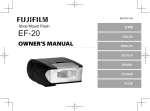
CCD Color Camera
GiantDragon Color series
CSGV90CC3
CSGX36CC3
CSGS20CC2
CSGU15CC18
Instruction Manual
Thank you for purchasing our product.
Before using this CCD Color Camera, please read through this instruction manual
carefully in order to use this product correctly and safely.
After reading, keep this instruction manual handy so that you can refer to, whenever
you need it.
Contents
Safety Precautions
1. Overview ·····························································································1
2. Features ·······························································································1
3. Configuration ······················································································2
4. Optional part························································································2
5. Explanation rear panel·········································································3
6. Connection ··························································································4
7. Functions ·····························································································5
8. Timing chart ························································································8
9. Troubleshooting··················································································10
10. Specifications ···················································································11
11. Outline Drawing···············································································17
Printed on recycled paper
D4153660A
Safety Precautions
Before using this product, read these safety precautions carefully. Important information is shown in this Instruction
Manual to protect users from bodily injuries and property damages, and to enable them to use the product safely and
correctly.
Please be sure to thoroughly understand the meanings of the following signs and symbols before reading the main
text that follow, and observe the instructions given herein.
[Definition of Safety Signs]
Safety Signs
WARNING
Description
Indicates a potentially hazardous situation that may result in death or
serious injury (*1) in the event of improper handling.
Indicates a potentially hazardous situation that may result in light to
CAUTION
moderate injuries (*2) or only in property damage (*3)in the event of
improper handling.
Notes *1: “Serious injury” refers to cases of loss of eyesight, wounds, burns (high or low temperature),
electric shock, broken bones, poisoning, etc., which leave after-effects or which require
hospitalization or a long period of outpatient treatment of cure.
*2: "Light to moderate injuries" refers to injuries, burns, electric shock etc. that do not require
hospitalization or long-term treatment.
*3: "Property damage" refers to cases of extensive damage involving damage to buildings, equipment,
farm animals, pet animals and other belongings.
[Explanation of Safety Symbols]
Safety Symbols
Description
PROHIBITED
This sign indicates PROHIBITION (Do not).
The content of prohibition is shown by a picture or words beside the
symbol.
MANDATORY
This sign indicates MANDATORY ACTION (You are required to
do).
The content of action is shown by a picture or words beside the
symbol.
D4153660A
[General Handing]
WARNING
Unplug
! Stop operation immediately when any abnormality or defect occurs.
If abnormal conditions are present, such as smoke, a burning smell, ingress of water or foreign
matter, or if the equipment is dropped or malfunctions, fire or electric shock may result.
Be always sure to disconnect the power cable from the wall socket at once and contact your
dealer.
! Do not use the equipment in locations subject to water splashes.
Otherwise, fire or electric shock may result.
Do not get wet
! Do not disassemble, repair, or modify the equipment.
Otherwise, fire or electric shock may result.
For internal repair, inspection, or cleaning, contact your sales representative.
Never pull apart
! Do not place anything on the equipment.
If metallic objects, liquid, or other foreign matter enters the equipment, fire or electric shock
may result.
Avoid
! Do not install the equipment in an unstable or inclined location or locations subject to
vibration or impact.
Otherwise, the equipment may topple over and cause personal injury.
Avoid
! During an electrical storm, do not touch the power cable and the connection cable.
Otherwise, an electric shock may result.
Do not touch
! Use the specified voltage.
Use of an unspecified voltage may result in fire or electric shock.
Instruction
Avoid
! Do not be handled roughly, damaged, fabricated, bent forcefully, pulled, twisted, bundled,
placed under heavy objects or heated the power cable and the connection cable.
Otherwise, fire or electric shock may result.
D4153660A
[General Handing]
CAUTION
Instruction
! Observe the following when installing the equipment:
· Do not cover the equipment with a cloth, etc.
· Do not place the equipment in a narrow location where heat is likely to accumulate.
Otherwise, heat will accumulate inside the equipment, possibly resulting in a fire.
! Do not place the equipment in locations subject to high moisture, oil fumes, steam, or
dust.
Otherwise, fire or electric shock may result.
Avoid
! Do not install the equipment in locations exposed to direct sunlight or humidity.
Otherwise, the internal temperature of the equipment will rise, which may cause a fire.
Avoid
! Use only specified the power cable and the connection cables.
Otherwise, fire or electric shock may result.
Instruction
! When performing connection, turn off power.
When connecting the power cable and the connection cable, turn off the equipment power.
Otherwise, fire or electric shock may result.
Instruction
! Do not expose its camera head to any intensive light (such as direct sunlight).
Otherwise, its inner image pickup device might get damaged.
Avoid
! Avoid short-circuiting signal output.
Otherwise, a malfunction may occur.
Avoid
Avoid
Instruction
! Avoid giving a strong shock against the camera body.
It might cause a breakdown or damage. If your camera is used in a system where its camera
connector is subjected to strong repetitive shocks, its camera connector is possible to break
down. If you intend to use your camera in such a situation, if possible, bundle and fix a camera
cable in the place near the camera, and do not transmit a shock to the camera connector.
! Contact your sales representative to request periodic inspection and cleaning (every
approx five years).
Accumulation of dust inside the equipment may result in fire or electric shock.
For inspection and cleaning costs, contact your sales representative.
D4153660A
CASES FOR INDEMNITY (LIMITED WARRANTY)
We shall be exempted from taking responsibility and held harmless for damage or losses incurred by the user in
the following cases.
! In the case damage or losses are caused by fire, earthquake, or other acts of God, acts by a third party,
deliberate or accidental misuse by the user, or use under extreme operating conditions.
! In the case of indirect, additional, consequential damages (loss of business interests, suspension of business
activities) are incurred as result of malfunction or non-function of the equipment, we shall be exempted from
responsibility for such damages.
! In the case damage or losses are caused by failure to observe the information contained in the instructions in
this instruction manual and specifications.
! In the case damage or losses are caused by use contrary to the instructions in this instruction manual and
specifications.
! In the case damage or losses are caused by malfunction or other problems resulting from use of equipment
(connected equipments including Gigabit Ethernet Interface board, the lens, etc.) or software that is not
specified.
! In the case damage or losses are caused by repair or modification conducted by the customer or any
unauthorized third party (such as an unauthorized service representative).
! Expenses we bear on this product shall be limited to the individual price of the product.
RESTRICTION FOR USE
! Should the equipment be used in the following conditions or environments, give consideration to safety
measures and inform us of such usage:
1. Use of the equipment in the conditions or environment contrary to those specified, or use outdoors.
2. Use of the equipment in applications expected to cause potential hazard to people or property, which
require special safety measures to be adopted.
! This product can be used under diverse operating conditions. Determination of applicability of equipment or
devices concerned shall be determined after analysis or testing as necessary by the designer of such
equipment or devices, or personnel related to the specifications. Such designer or personnel shall assure the
performance and safety of the equipment or devices.
! This product is not designed or manufactured to be used for control of equipment directly concerned with
human life (*1) or equipment relating to maintenance of public services/functions involving factors of
safety (*2). Therefore, the product shall not be used for such applications.
(*1): Equipment directly concerned with human life refers to.
· Medical equipment such as life-support systems, equipment for operating theaters.
· Exhaust control equipment for exhaust gases such as toxic fumes or smoke.
· Equipment mandatory to be installed by various laws and regulations such as the Fire Act or
Building Standard Law
· Equipment related to the above
(*2) :Equipment relating to maintenance of public services/functions involving factors of safety refers to.
· Traffic control systems for air transportation, railways, roads, or marine transportation
· Equipment for nuclear power generation
· Equipment related to the above
D4153660A
Notes on using this product
! Handle carefully
Do not drop the equipment or allow it to be subject to strong impact or vibration, as such action may cause
malfunctions. Further, do not damage the connection cable, since this may cause wire breakage.
! Environmental operating conditions
Do not use the product in locations where the ambient temperature or humidity exceeds the specifications.
Otherwise, image quality may be degraded or internal components may be adversely affected. In particular,
do not use the product in areas exposed to direct sunlight. Moreover, during shooting under high
temperatures, vertical stripes or white spots (noise) may be produced, depending on the subject or camera
conditions (such as increased gain). However, such phenomena are not malfunctions.
! Check a combination with the lens
Depending on the lens and lighting you use, an image is reflected as a ghost in the imaging area. However,
this is not because of a fault of the camera.
In addition, depending on the lens you use, the performance of the camera may not be brought out fully due
to deterioration in resolution and brightness in the peripheral area, aberration and others.
Be sure to check a combination with the camera by using the lens and lightning you actually use.
When installing a lens in the camera, make sure carefully that it is not tilted.
In addition, use a mounting screw free from defects and dirt. Otherwise, the camera may be unable to be
removed.
! Do not shoot under intense light
Avoid intense light such as spot lights on part of the screen because it may cause blooming or smears. If
intense light falls on the screen, vertical stripes may appear on the screen, but this is not a malfunction.
! Occurrence of moiré
If you shoot thin stripe patterns, moiré patterns (interference fringes) may appear. This is not a malfunction.
! Occurrence of noise on the screen
If an intense magnetic or electromagnetic field is generated near the camera or connection cable, noise may
be generated on the screen. If this occurs, move the camera or the cable.
! Handling of the protective cap
If the camera is not in use, attach the lens cap to the camera to protect the image pickup surface.
! If the equipment is not to be used for a long duration
Turn off power to the camera for safety.
! Maintenance
Turn off power to the equipment and wipe it with a dry cloth.
If it becomes severely contaminated, gently wipe the affected areas with a soft cloth dampened with diluted
neutral detergent. Never use alcohol, benzene, thinner, or other chemicals because such chemicals may
damage or discolor the paint and indications.
If the image pickup surface becomes dusty, contaminated, or scratched, consult your sales representative.
! Disposal
When disposing of the camera, it may be necessary to disassemble it into separate parts, in accordance with
the laws and regulations of your country and/or municipality concerning environmental contamination.
D4153660A
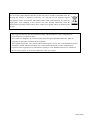
Following information is only for EU-member states:
The use of the symbol indicates that this product may not be treated as household waste. By
ensuring this product is disposed of correctly, you will help prevent potential negative
consequences for the environment and human health, which could otherwise be caused by
inappropriate waste handling of this product. For more detailed information about the
take-back and recycling of this product, please contact your supplier where you purchased the
product.
This equipment has been tested and found to comply with the limits for a class A digital device,
pursuant to Part 15 of the FCC Rules.
These limits are designed to provide reasonable protection against harmful interference when the
equipment is operated in a commercial environment.
This equipment generates, uses, and can radiate radio frequency energy and, if not installed and used in
accordance with the instruction manual, may cause harmful interference to radio communication.
Operation of this equipment in a residential area is likely to cause harmful interference in which case
the user will be require to correct the interference at his own expense.
D4153660A
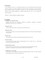
10
中华人民共和国
环保使用期限
环保使用期限标识,是根据电子信息产品污染控制管理办法以及,电子
信息产品污染控制标识要求(SJ/T11364-2006)、电子信息产品环保使用
期限通则,制定的适用于中国境内销售的电子信息产品的标识。
电子信息产品只要按照安全及使用说明内容,正常使用情况下,从生产
月期算起,在此期限内,产品中含有的有毒有害物质不致发生外泄或突
变,不致对环境造成严重污染或对其人身、财产造成严重损害。
产品正常使用后,要废弃在环保使用年限内或者刚到年限的产品时,请
根据国家标准采取适当的方法进行处置。
另外,此期限不同于质量/功能的保证期限。
The Mark and Information are applicable for People's Republic of China
only.
<产品中有毒有害物质或元素的名称及含量>
产品中有毒有害物质或元素的名称及含量>
有毒有害物质或元素
部件名称
六价铬
多溴联苯
多溴二苯醚
铅(Pb)
汞(Hg)
镉(Cd)
(Cr(VI))
(PBB)
(PBDE)
相机本体
×
○
○
○
○
○
○:表示该有毒有害物质在该部件所有均质材料中的含量均在电子信息产品中有毒有害物质的
限量要求标准规定的限量要求(SJ/T11363-2006)以下
×:表示该有毒有害物质至少在该部件的某一均质材料中的含量超出电子信息产品中有毒有害
物质的限量要求标准规定的限量要求(SJ/T11363-2006)
This information is applicable for People's Republic of China only.
リサイクルに
リサイクルに関する情報
する情報(
情報(包装物)
包装物)
有关再利用的信息(
有关再利用的信息(包装物)
包装物)
Information on recycling of wrapping composition
箱/箱子/
箱子/Box
内部緩衝材料
内部缓冲材料
Internal buffer materials
CB
段ボール
瓦楞纸板
Corrugated cardboard
OTHERS
D4153660A
1. Overview
This GiantDragon Color series is an integrated-(one-body)-type color camera that adopts all pixel data readout
inter line CCD. There are 4 models according to the sensor type. These are CSGV90CC3 (VGA), CSGX36CC3
(XGA), CSGS20CC2 (SXGA), and CSGU15CC18 (UXGA). For video output, the Gigabit Ethernet®* interface
standard “IEEE802.3ab” is adopted for high transfer rate, and it is easy to integrate into industrial equipment.
* Ethernet® is a registered trademark of XEROX Corporation.
2. Features
! High frame rate and high resolution
Supported high frame rate CSGV90CC3 (90fps/VGA), CSGX36CC3 (36fps/XGA), CSGS20CC2
(20fps/SXGA), and CSGU15CC18 (15fps/UXGA).
! All pixel readout
All pixel signals (in the effective area) are output in one frame processing.
! Full frame shutter
Since all pixels are output even by shutter operation, high resolution can be achieved, without deteriorating
the vertical resolution.
! Square grids
The CCD pixels arrayed in square grids facilitates computation for image processing.
! Color processing
Since color processing is built in, there are also RGB (24bit), YUV 4:2:2 (16bit), YUV 4:1:1 (12bit) output
modes besides Raw output mode (8/10bit).
! Gigabit Ethernet interface
Performs video output and camera control via the Gigabit Ethernet standard IEEE802.3ab interface. Data
transfer is at 1Gbps that can output uncompressed video data of high frame rate.
! GigEVision Ver 1.0 conformity
This product is based on GigEVision Camera Interface Standard for Machine Vision Ver 1.0 that is industrial
camera standard. Therefore, control of this camera is easy.
! GenICam Ver 1.0 conformity
This product is based on GenICam Generic Interface for Cameras Ver 1.0 that is industrial camera standard.
Therefore, control of this camera is easy.
1
D4153660A
! High-speed draft readout mode
By thinning out vertical lines, it can be read all effective area at high-speed frame rate.
! Random trigger shutter
The random trigger shutter function provides images in any timing by input of an external trigger signal.
Trigger control from PC is possible.
! Scalable
Selectable video output area. It can be higher frame rate by reducing vertical output area. And can be reduce
occupied data rate of Gigabit Ethernet by reducing horizontal output area.
! Compact and lightweight
This camera is compact and lightweight, and it is easy to integrate into industrial equipment.
! EU RoHS & Chinese ROHS compliant
3. Configuration
(1) Camera body ············································ 1
(2) Accessories
- Instruction Manual (Japanese) ············· 1
- Instruction Manual (English) ··············· 1
* No application software is attached to this camera.
4. Optional part
(1) Camera mounting kit·································· Model name: CPT8420
(2) Camera cable ············································· Model name: CPRC3910-**
(3) Camera adapter·········································· Model name: CA130C
* Contact your dealer / distributor for details of option units.
2
D4153660A
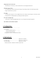
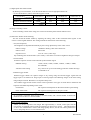
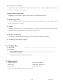
5. Explanation rear panel
(1) Ethernet
Gigabit Ethernet Interface connector
- Connector model
P65-P01-19V8 (Supplied by SpeedTech Corp.)
- Pin assignment
Pin No.
I/O
Function
1
I/O
BI_DA+
2
I/O
BI_DA-
3
I/O
BI_DB+
4
I/O
BI_DC+
5
I/O
BI_DC-
6
I/O
BI_DB-
7
I/O
BI_DD+
8
I/O
BI_DD-
(2)
(1)
LED1
Rear View
- Indication LED1: GREEN (ACT LED)
LED2
LED1 indicates the state of ACT.
During transfer:
Lighting
- Indication LED2: YELLOW (LINK LED)
LED2 indicates the state of LINK.
During Link:
Lighting
* LINK LED indicates establishment of Link of 1000BASE. Therefore, in the case of 100BASE/10BASE,
LINK LED does not light.
(2) DC_IN / TRIGGER
- Connector (Camera side)
HR10A-7R-6PB(73)
(Supplied by HIROSE ELECTRIC CO., LTD.)
- Plug (Cable side)
HR10A-7P-6S(73)
(Supplied by HIROSE ELECTRIC CO., LTD.)
or equivalents
* This camera cable is not an accessory of this product.
- Pin assignment
Pin No.
Signal Name
[Standard specification]
1
BUSY_OUT
2
GND
3
GND
4
TRIG_IN
5
EXPOSE_OUT
6
+12V
1
6
2
5
3
4
* Above figure is connector view from insert side.
3
D4153660A
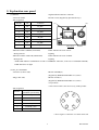
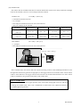
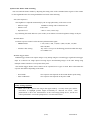
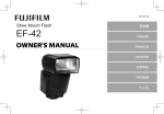
6. Connection
Connect this camera as shown in the figure below.
(The figure below shows an example of connection. For details, contact our sales representative.)
Option
CameraCable
CPRC3910-**
Option
CameraAdapter
CA130C
TRIGGER
HD
AC100VIN
WEN
CA13 0 C
SERIALNo .
VD
CCD Color Camera
GiantDragon
(Rear-side)
CAMERA
VIDEO OUT CLOCK OUT
TYPE2 23 2 A5 90 0
AC1 00 V 0 .1 5 A
AC100V
50/60Hz
LAN Cable
Twist-pair
Category 5e orover
PC
GigabitEthernet
interfaceboard
Notes on Connection:
- If your camera is used in a system where its connectors are subjected to strong repetitive shocks,
its connectors are possible to break down. If you use your camera in such a situation, use an
LAN cable with a lock screw, and secure the camera cable as close as possible to the camera
body for avoid physical shock to the camera connector.
- Since the Optional parts and Gigabit Ethernet interface board, cable not attached to this product,
please prepare it if necessary.
4
D4153660A
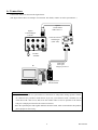
7. Functions
Control and setting of functions can be done by the camera control based on the Gigabit Ethernet digital camera
protocol (GigEVision Ver.1.00).
(1) Image output
A format of the output image and frame rate which this GiantDragon Color series supports is as follows.
Model
CSGV90CC3
CSGX36CC3
CSGS20CC2
CSGU15CC18
GVSP_PIX_YUV411_PACKED: YUV4:1:1 12bit
GVSP_PIX_YUV422_PACKED: YUV4:2:2 16bit
GVSP_PIX_RGB8_PACKED: RGB 24bit
Image output format
GVSP_PIX_BAYRG8
GVSP_PIX_BAYGB8
GVSP_PIX_BAYRG8
Raw(BayRG8)8bit
Raw(BayGB8) 8bit
Raw(BayRG8)8bit
GVSP_PIX_BAYRG10
GVSP_PIX_BAYGB10
GVSP_PIX_BAYRG10
Raw(BayRG10)10bit
Raw(BayGB8) 10bit
Raw(BayRG10)10bit
Frame rate
Maximum
Maximum
Maximum
Maximum
(at the all pixel readout)
90fps
36fps
20fps
15fps
Notes on Frame Drops of Image:
- Depends on your PC or Gigabit Ethernet interface board configurations, images may not be
captured normally (e.g. frame drops may occur). In this case, change to frame rate setting
lower.
(2) Setup-level setting
You can set the Setup-level in 192 steps in the range between 6.3 and 25%.
(3) Gain setting
There is AGC (Auto Gain Control) other than manual setting, too. Setting range and effective range are 0
to +6dB.
(4) White balance
There are two types of white balancing mode, MWB (Manual White Balance) and OPWB (One Push
White Balance). You can set white balancing mode, according to the subject and purpose.
(5) Gamma correction
You can set gamma correction ON/OFF.
* The user cannot adjust the correction amount.
(6) Masking correction
The hue of images is masking corrected so that it will be natural (ON fixed).
* The user cannot adjust the correction amount.
5
D4153660A
(7) High-speed draft readout mode
By thinning out vertical lines, it can be read all effective area at high-speed frame rate.
* As for CSGV90CC3 (VGA), this mode supports a fault.
CSGV90CC3
CSGX36CC3
CSGS20CC2
CSGU15CC18
Draft mode
1/3
1/2
1/4
Readout vertical line number
254
480
300
86 fps
34fps
46fps
Maximum frame rate
(8) Image resending control
As the resending control of the image, this camera resends the packet which suffered a loss.
(9) Electronic shutter mode switching
You can switch the shutter modes by adjusting the setting value of the command status register of the
camera via the Gigabit Ethernet. The setting method has three kinds of the following.
- AE (Auto Exposure)
The brightness is adjusted automatically by the average photometry of the entire screen.
Effective range
1/20000s to Setting value of the frame rate
Effective area
Full screen
Exposure level
-1EV to +1EV (1/3EV step)
By combining this mode and AGC (ALC mode), it can follow so much to brightness change of subject.
- Normal shutter
Performs exposure control via the internal synchronization signal.
PRESET setting:
1/100s, 1/250s, 1/500s, 1/1000s, 1/2000s , 1/4000, 1/10000,
and 1/20000s
Absolute value setting
Any value is set up in 32-bit floating point form within the range
of 1/20000s to 2s
- Random trigger shutter
Random trigger shutter can capture images at any timing using the external trigger signal and soft
trigger input. It is effective for image input of moving objects and obtaining images of the same timing
using multiple cameras. But there is an exposure delay time.
The random trigger shutter of this camera can be operated in two types of mode. How to determine the
exposure time differs depending on the mode.
Fixed mode:
The exposure time depends on the normal shutter speed setting.
Pulse width mode :
The exposure time depends on the pulse width.
Notes on fixed mode of Random trigger shutter:
- It is outside a guarantee when having set it as this mode, and a normal shutter is turned off.
Please be sure to turn on a normal shutter.
Notes on long exposure:
- When you set the exposure time longer than approximately 1 second, white spots and the
unevenness in highlight portion might occasionally be observed on screen. This phenomenon
is due to the characteristics of the CCD image-pickup device, and do not reflect performance
error in the pickup device or CCD Camera itself.
6
D4153660A
(10) Scalable mode
This camera has the scalable mode that can read out defined area of the screen. Only continuous rectangle
units can be selected, concave or convex shape cannot be selected.
- Window size:
{A x m(H)} x {B x n(V)}
* A and B are minimum unit size.
* m, n=integer
* The image of maximum unit size or less can be selected.
* Only one window can be selected.
Minimum unit size
(H) x (V)
Maximum unit size
(H) x (V)
- Start address:
CSGV90CC3
CSGX36CC3
CSGS20CC2
CSGU15CC18
160 x 120
256 x 192
160 x120
200 x 150
640 x 480
1024 x 768
1280 x 960
1600 x 1200
{32 x i(H)} x {24 x j(V)}
* i, j=integer
* The image of maximum unit size or less can be selected.
(X,
(3232x*i,i 24
( XY)
, Y=)=(
, 24x *j)j )
BB x* nn
⇒
A x* m
In the scalable mode, this camera reads out only the necessary portions at the standard speed while it scans
through other unnecessary portions at high speed, so the trigger interval can be shorter if the vertical cutout
width is small. However, the trigger interval cannot be short in the horizontal direction even if the cutout
width is small due to the operation mechanism of the CCD sensor.
Notes on scalable mode:
- White lines may occur in the upper portions of the screen when strong light exists in a wide area
during the scalable mode. This is not a malfunction. If white lines occur, adjust the amount of
incident light using the lens.
7
D4153660A
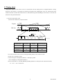
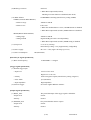
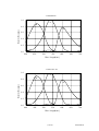
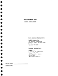
8. Timing chart
Image data outputs of this camera series are transferred with the UDP protocol of Gigabit Ethernet. Timing
numerical value below is prescribed by absolute prerequisite that GiantDragon series use transmission band
without restriction of other node. When there is a node transferring with GiantDragon concerned, it is not same the
numerical value prescribed below.
(1) In the normal shutter mode
Video format: RGB 24 bit, all pixel readout
Expose
GbE bus
Image
Image
Image
T1
TDLY1
T2
T DLY2
T2
Model name
T1 [ms]
T2 [ms]
Frame rate [ms]
CSGV90CC3
0.5
7.7
11.1
CSGX36CC3
0.5
19.3
27.8
CSGS20CC2
1.0
30.0
50.0
CSGU15CC18
1.0
46.8
66.7
* T1 is the maximum value, and T2 (GVSP_FRAME_RATE) is the minimum value.
* Frame rate is maximum speed.
* At the setting the GVSP_SIZE (SCPSx) = 1500 byte / packet.
(T2 is changed by GVSP_SIZE (SCPSx).)
* Set the value that TDLY1 (GVSP_BLOOK_START_DELAY) to satisfy the next numerical formula;
T1 + TDLY1 + T2 >= Frame rate
8
D4153660A
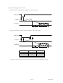
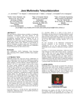
(2) In the random trigger shutter mode
- When fixed mode (Video format: RGB 24 bit, all pixel readout);
TRIG_IN
T3
Expose
GbE bus
Image
T1 TDLY1
T2
- When pulse width mode (Video format: RGB 24 bit, all pixel readout);
TRIG_IN
T3
T4
Expose
GbE bus
Image
T1 TDLY1
T2
Model name
T3 [us]
T4 [us]
CSGV90CC3
0.9
2.8
CSGX36CC3
1.5
25.2
CSGS20CC2
3.4
5.1
CSGU15CC18
1.9
7.5
* The value of T1 and T2 are the same as the value at the of the normal shutter setting.
9
D4153660A
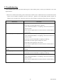
9. Troubleshooting
If any trouble occurs in use, check the following first. If the trouble persists, contact your distributor or our sales
representatives.
* When user confirms the troubles, please confirms the troubles on the condition that user connected the camera
system on the smallest composition and set 1500 byte / packet to the GVSP_SIZE (SCPSx) register for
making cause of trouble clear. About the connection of the smallest constitution, please refer to 6.Connection.
Phenomena
Cannot turn on power
Check item
- Check the connection of the Camera cable.
- Check that the LINK LED(LED2) is lighting.
If the LINK LED(LED2) is not lighting, check the connection of
the LAN cable.
- Check that the Gigabit Ethernet interface board is installed and set
up correctly.
Shooting image is not displayed
- Check that the LINK LED(LED2) is lighting.
If the LINK LED(LED2) is not lighting, check the connection of
the LAN cable.
- Check that the ACT LED(LED1) is lighting or blinking.
- Check that the camera register settings are correct.
- Check that the lens aperture is not closed.
- Check that the Gigabit Ethernet interface board is installed and set
up correctly.
Frame drop occurs on shooting
image
Shooting image remains still
- If some boards are installed in the PCI slots, remove the other
boards.
- Check that the camera is not in the random trigger mode.
- Check that the ACT LED(LED1) is lighting or blinking.
Cannot control camera from PC
- Check that the LINK LED(LED2) is lighting.
If the LINK LED(LED2) is not lighting, check the connection of
the LAN cable.
- Check that the Gigabit Ethernet interface board is installed and set
up correctly.
10
D4153660A
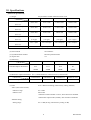
10. Specifications
[Electrical specification]
(1) Imager
All-pixel-data-readout interline transfer CCD
CSGV90CC3
CSGX36CC3
CSGS20CC2
CSGU15CC18
692 x 504
1077 x 788
1434 x 1050
1688 x 1248
659 x 494
1034 x 779
1392 x 1040
1628 x 1236
640 x 480
1024 x 768
1280 x 960
1600 x 1200
Scanning area
4.88 x 3.66 mm2
4.81 x 3.62 mm2
6.47 x 4.84 mm2
7.16 x 5.44 mm2
(H) x (V)
(1/3 type)
(1/3 type)
(1/2 type)
(1/1.8 type)
7.4 x 7.4µm2
4.65 x 4.65µm2
4.65 x 4.65µm2
4.40 x 4.40µm2
Number of total pixels
(H) x (V)
Number of effective pixels
(H) x (V)
Number of Video out pixels
(H) x (V)
Pixel size
(H) x (V)
Color filter
RGB primary color mosaic-on-tip color filter
(2) Scan method
Non-interlace
(3) Synchronization method
Internal synchronization
(4) Aspect ratio
4:3
(5) Sensitivity
Standard subject illuminance
CSGV90CC3
CSGX36CC3
CSGS20CC2
CSGU15CC18
1700 lx
2400 lx
1400 lx
1000 lx
F5.6
F5.6
F5.6
F8
5000K
5000K
5000K
5000K
(6) Minimum subject illuminance (F1.4, GAIN Maximum, video level 50 %, Gamma ON)
Minimum subject illuminance
(7) Gain
CSGV90CC3
CSGX36CC3
CSGS20CC2
CSGU15CC18
20 lx
27 lx
18 lx
7 lx
AGC / Manual switching (initial factory setting: Manual)
- AGC (Auto Gain Control)
Effective range
0 to +6dB
Effective area
Full screen
* When the random shutter is active, AGC function is disabled.
* When Raw output mode (8/10bit), AGC function is disabled.
- Manual setting
Setting range
0 to +6 dB (46 step, initial factory setting: 0 dB)
11
D4153660A
(8) Gamma correction
ON(Gamma = 0.65) /OFF(Gamma = 1.0) switching
initial factory setting: ON
* When Raw output mode(8/10bit),
Gamma correction function is disabled (OFF fixed).
(9) Masking correction
ON fixed
* When Raw output mode(8/10bit),
Masking correction function is disabled (OFF fixed).
(10) White balance
OPWB / MWB switching (initial factory setting: MWB)
- OPWB (One Push White Balance)
Effective range
2500 K to 6500 K
Effective area
Full screen
* When the random shutter is active, OPWB function is disabled.
* When Raw output mode (8/10bit), OPWB function is disabled.
- MWB (Manual White Balance)
Setting range
2500 K to 6500 K
Setting method
R-gain and B-gain can be set independently.
* When Raw output mode (8/10bit), MWB setting is disabled.
(11) Setup-level
6.3 to 25 % (192step)
initial factory setting: 6.3% [Approximately 16digit/8bit]
* When Raw output mode (8/10bit), Setup-level setting is disabled.
(12) Power supply
DC 12V +/-10% (ripple 100 mV(p-p) or less)
(13) Power consumption
3W Max (Maximum)
[Internal sync signal specification]
(1) Base clock frequency
36.0000 MHz +/- 100ppm
[Trigger signal specification]
]
(1) External trigger input
- Input level
Low level: 0 to 0.5V
High level: 2.0 to 5.0V
- Polarity
Positive / Negative bipolar
- Pulse width
2us (Minimum)
- Input impedance
High impedance
(2) Software trigger
Set via the Gigabit Ethernet interface
[Output signal specification]
(1) BUSY_OUT
The period that input of the trigger signal is forbidden.
- Output level
LVTTL
- Polarity
Positive
(2) EXPOSE_OUT
The period that this camera exposes.
- Output level
LVTTL
- Polarity
Positive
12
D4153660A
[Electronic shutter specification]
]
(1) AE(Auto Exposure)
- Effective range
1/20000s to Setting value of the frame rate
- Effective area
Full screen
- Exposure level
-1EV to +1EV (1/3EV step)
* When the random shutter is active, AE function is disabled.
* When Raw output mode (8/10bit), AE function is disabled.
(2) Normal shutter
- PRESET setting
1/100s, 1/250s, 1/500s, 1/1000s, 1/2000, 1/4000,
1/10000, 1/20000s
- Absolute value setting
any value is set up in 32-bit floating point form within the range
of 1/20000s to 2s.
(3) Random trigger shutter
-Fixed mode
The exposure time depends on the normal shutter speed setting.
-Pulse width mode
The exposure time depends on the pulse width.
[Interface specification]
(1) Interface system
Gigabit Ethernet IEEE802.3ab (1000BASE-T) conformity
(2) Transmission speed
1Gbps (Maximum)
(3) Video output
depends on 7.Functions (1) Format of output image
(4) Protocol
GigEVision Camera Interface Standard for Machine Vision
Ver. 1.0 conformity
(5) Conformity Cable
Twist pair (Category 5e or over)
(6) Cable length
To 100m (at the Unshielded Twist Pair (UTP) cable using)
(7) Recommended cable
Oki Electric Cable Co., Ltd
HONDA TSUSHIN KOGYO CO., LTD
High bending resistance shielded Cat5e LAN cable
* Because above recommendation cable is high bending resistance,
maximum length of cable is 40m.
* Contact your dealer / distributor for details
of recommended cable.
13
D4153660A
[Machine externals specification]]
]
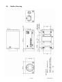
(1) Dimensions
44mm(W) x 29mm(H) x 70mm(D) (Not including protrusion)
(2) Mass
Approximately 120g
(3) Lens mount
C-mount
Notes on combination of C-mount lens:
- Depending on the lens you use, the performance of the camera may not be brought out fully due
to the deterioration in resolution and brightness in the peripheral area, occurrence of a ghost,
aberration and others. When you check the combination between the lens and camera, be sure to
use the lens you actually use. As for the C-mount lens used combining this camera, the projection
distance from bottom of the screw should use 9.4mm or less.
Bottom of
the screw
C-mount lens
9.4mm or less
(4) Flange back
it is not possible to adjust it.
(5) Camera body grounding: insulation status
Conductive between circuit GND and camera body
[Operating Ambient conditions]
]
(1) Ambient conditions
- Performance assurance
Temperature
0 to 40°C
Humidity
10 to 90% (no condensation)
- Operating assurance
Temperature
-5 to 45°C
Humidity
90% or less (no condensation)
- Storage assurance
Temperature
-20 to 60°C
Humidity
90% or less (no condensation)
(2) EMC conditions
- EMI (Electro-Magnetic interference)
EN61000-6-4 conformity
FCC part15 Subpart B class A conformity
- EMS (Electro-Magnetic susceptibility) EN61000-6-2 conformity
Notes on Conformity of the EMC:
- About the conformity of the EMC standard of this machine, it has guaranteed in the conditions
combined with the option part of 4th clause.
When used combining parts other than specification of our company, I ask you to have final EMC
conformity checked of a visitor with a machine and the whole equipment.
14
D4153660A
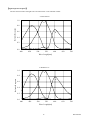
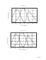
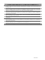
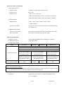
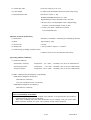
[Typical spectral response]
]
The lens characteristics and light source characteristics is not reflected in table.
<CSGV90CC3>
1.0
G
Relative Responce
0.8
B
0.6
R
0.4
0.2
0.0
400
450
500
550
600
650
700
650
700
Wave Length[nm]
<CSGX36CC3>
1.0
G
Relative Responce
0.8
B
R
0.6
0.4
0.2
0.0
400
450
500
550
600
Wave Length[nm]
15
D4153660A
<CSGS20CC2>
1.0
G
B
Relative Responce
0.8
R
0.6
0.4
0.2
0.0
400
450
500
550
600
650
700
Wave Length[nm]
<CSGU15CC18>
1.0
G
B
0.8
Relative Responce
R
0.6
0.4
0.2
0.0
400
450
500
550
600
650
700
Wave Length[nm]
16
D4153660A
11. Outline Drawing
17
D4153660A
NOTE
D4153660A
NOTE
D4153660A
Head Office : 7-1, 4 chome, Asahigaoka, Hino-shi, Tokyo, 191-0065, Japan
(Overseas Sales Department)
Phone : +81-42-589-8771
Fax
: +81-42-589-8774
URL
: http://www.toshiba-teli.co.jp
Distributor
•This product must be classified for disposal according to the laws of each country and municipal laws.
•Information contained in this document is subject to change without prior notice.
D4153660A
CCD Color Camera
GiantDragon Color Series
CSGV90CC3
CSGX36CC3
CSGS20CC2
CSGU15CC18
Specifications
Contents
CASES FOR INDEMNITY (LIMITED WARRANTY)
RESTRICTION FOR USE
Notes on using this product
1.
Overview····································································1
2.
Features ·····································································1
3.
Configuration ····························································2
4.
Optional part·····························································2
5.
Functions ···································································3
6.
Specifications·····························································6
7.
Timing chart····························································13
8.
Guarantee································································15
9.
Repair ······································································15
10. Outline Drawing······················································16
Printed on recycled paper
D4153497A
CASES FOR INDEMNITY (LIMITED WARRANTY)
We shall be exempted from taking responsibility and held harmless for damage or losses incurred by the user in
the following cases.
! In the case damage or losses are caused by fire, earthquake, or other acts of God, acts by a third party,
deliberate or accidental misuse by the user, or use under extreme operating conditions.
! In the case of indirect, additional, consequential damages (loss of business interests, suspension of business
activities) are incurred as result of malfunction or non-function of the equipment, we shall be exempted from
responsibility for such damages.
! In the case damage or losses are caused by failure to observe the information contained in the instructions in
this instruction manual and specifications.
! In the case damage or losses are caused by use contrary to the instructions in this instruction manual and
specifications.
! In the case damage or losses are caused by malfunction or other problems resulting from use of equipment or
software that is not specified.
! In the case damage or losses are caused by repair or modification conducted by the customer or any
unauthorized third party (such as an unauthorized service representative).
! Expenses we bear on this product shall be limited to the individual price of the product.
D4153497A
RESTRICTION FOR USE
! Should the equipment be used in the following conditions or environments, give consideration to safety
measures and inform us of such usage:
1. Use of the equipment in the conditions or environment contrary to those specified, or use outdoors.
2. Use of the equipment in applications expected to cause potential hazard to people or property, which
require special safety measures to be adopted.
! This product can be used under diverse operating conditions. Determination of applicability of equipment or
devices concerned shall be determined after analysis or testing as necessary by the designer of such
equipment or devices, or personnel related to the specifications. Such designer or personnel shall assure the
performance and safety of the equipment or devices.
! This product is not designed or manufactured to be used for control of equipment directly concerned with
human life (*1) or equipment relating to maintenance of public services/functions involving factors of
safety (*2). Therefore, the product shall not be used for such applications.
(*1): Equipment directly concerned with human life refers to.
· Medical equipment such as life-support systems, equipment for operating theaters.
· Exhaust control equipment for exhaust gases such as toxic fumes or smoke.
· Equipment mandatory to be installed by various laws and regulations such as the Fire Act or
Building Standard Law
· Equipment related to the above
(*2) :Equipment relating to maintenance of public services/functions involving factors of safety refers to.
· Traffic control systems for air transportation, railways, roads, or marine transportation
· Equipment for nuclear power generation
· Equipment related to the above
D4153497A
Notes on using this product
! Handle carefully
Do not drop the equipment or allow it to be subject to strong impact or vibration, as such action may cause
malfunctions. Further, do not damage the connection cable, since this may cause wire breakage.
! Environmental operating conditions
Do not use the product in locations where the ambient temperature or humidity exceeds the specifications.
Otherwise, image quality may be degraded or internal components may be adversely affected. In particular,
do not use the product in areas exposed to direct sunlight. Moreover, during shooting under high
temperatures, vertical stripes or white spots (noise) may be produced, depending on the subject or camera
conditions (such as increased gain). However, such phenomena are not malfunctions.
! Regarding a lens mount
Depending on the lens you use, the performance of the camera may not be brought out fully due to the
deterioration in resolution and brightness in the peripheral area, occurrence of a ghost, aberration and
others. When you check the combination between the lens and camera, be sure to use the lens you actually
use.
As for the C-mount lens used combining this camera, the projection distance from bottom of the screw
should use 9.4mm or less.
Bottom of
C-mount lens
the screw
9.4mm or less
! Check a combination with the lens
Depending on the lens and lighting you use, an image is reflected as a ghost in the imaging area. However,
this is not because of a fault of the camera.
In addition, depending on the lens you use, the performance of the camera may not be brought out fully due
to deterioration in resolution and brightness in the peripheral area, aberration and others.
Be sure to check a combination with the camera by using the lens and lightning you actually use.
When installing a lens in the camera, make sure carefully that it is not tilted.
In addition, use a mounting screw free from defects and dirt. Otherwise, the camera may be unable to be
removed.
! Do not shoot under intense light
Avoid intense light such as spot lights on part of the screen because it may cause blooming or smears. If
intense light falls on the screen, vertical stripes may appear on the screen, but this is not a malfunction.
! Occurrence of moiré
If you shoot thin stripe patterns, moiré patterns (interference fringes) may appear. This is not a malfunction.
! Occurrence of noise on the screen
If an intense magnetic or electromagnetic field is generated near the camera or connection cable, noise may
be generated on the screen. If this occurs, move the camera or the cable.
! Handling of the protective cap
If the camera is not in use, attach the lens cap to the camera to protect the image pickup surface.
D4153497A
! If the equipment is not to be used for a long duration
Turn off power to the camera for safety.
! Maintenance
Turn off power to the equipment and wipe it with a dry cloth.
If it becomes severely contaminated, gently wipe the affected areas with a soft cloth dampened with diluted
neutral detergent. Never use alcohol, benzene, thinner, or other chemicals because such chemicals may
damage or discolor the paint and indications.
If the image pickup surface becomes dusty, contaminated, or scratched, consult your sales representative.
! Disposal
When disposing of the camera, it may be necessary to disassemble it into separate parts, in accordance with
the laws and regulations of your country and/or municipality concerning environmental contamination.
D4153497A
1. Overview
This GiantDragon Color series is an integrated-(one-body)-type color camera that adopts all pixel data readout
inter line CCD. There are 4 models according to the sensor type. These are CSGV90CC3 (VGA), CSGX36CC3
(XGA), CSGS20CC2 (SXGA), and CSGU15CC18 (UXGA). For video output and camera control, the Gigabit
Ethernet®* interface standard “IEEE802.3ab” is adopted for high transfer rate, and it is easy to integrate into
industrial equipment.
*Ethernet® is a registered trademark of XEROX Corporation.
2. Features
(1) High frame rate and high resolution
Supported high frame rate CSGV90CC3 (90fps/VGA), CSGX36CC3 (36fps/XGA), CSGS20CC2
(20fps/SXGA), and CSGU15CC18 (15fps/UXGA).
(2) All pixel readout
All pixel signals (in the effective area) are output in one frame processing.
(3) Full frame shutter
Since all pixels are output even by shutter operation, high resolution can be achieved, without deteriorating the
vertical resolution.
(4) Square grids
The CCD pixels arrayed in square grids facilitates computation for image processing.
(5) Color processing
Since color processing is built in, there are also RGB (24bit), YUV 4:2:2 (16bit), YUV 4:1:1 (12bit) output
modes besides Raw output mode (8/10bit).
(6) Gigabit Ethernet interface
Performs video output and camera control via the Gigabit Ethernet standard IEEE802.3ab interface.
Data transfer is at 1Gbps that can output uncompressed video data of high frame rate.
(7) GigEVision Ver 1.0 conformity
This product is based on GigEVision Camera Interface Standard for Machine Vision Ver 1.0 that is industrial
camera standard. Therefore, control of this camera is easy.
(1/16)
D4153497A
(8) GenICam Ver 1.0 conformity
This product is based on GenICam Generic Interface for Cameras Ver 1.0 that is industrial camera standard.
Therefore, control of this camera is easy.
(9) High-speed draft readout mode
By thinning out vertical lines, it can be read all effective area at high-speed frame rate.
(10) Random trigger shutter
The random trigger shutter function provides images in any timing by input of an external trigger signal.
Trigger control from PC is possible.
(11) Scalable
Selectable video output area. It can be higher frame rate by reducing vertical output area. And can be reduce
occupied data rate of Gigabit Ethernet by reducing horizontal output area.
(12) Compact and lightweight
This camera is compact and lightweight, and it is easy to integrate into industrial equipment.
(13) EU RoHS & Chinese ROHS compliant
3. Configuration
(1) Camera body
・・・・・・・・・・・・・・・・・・・・・・・・・・・・・・・・・・・・・・・・・・・・・・・・・・・・・ 1
(2) Accessories
- Instruction Manual (Japanese) ・・・・・・・・・・・・・・・・・・・・・・・・・・・・・・・・・・・・・・・・・・・・・・・・・・・・・
- Instruction Manual (English)
1
・・・・・・・・・・・・・・・・・・・・・・・・・・・・・・・・・・・・・・・・・・・・・・・・・・・・・ 1
* No application software is attached to this camera.
4. Optional part
- Camera mounting kit
Model name: CPT8420
- Camera cable
Model name: CPRC3910-**
- Camera adapter
Model name: CA130C
* Contact your dealer / distributor for details of option units.
(2/16)
D4153497A
5. Functions
(1) Setup-level setting
You can set the pedestal in 192 steps in the range between 6.3 and 25%.
(2) Gain setting
There is AGC (Auto Gain Control) other than manual setting, too. Setting range and effective range are 0 to
+6dB.
(3) White balance
There are two types of white balancing mode, MWB (Manual White Balance) and OPWB (One Push White
Balance). You can set white balancing mode, according to the subject and purpose.
(4) Gamma correction
You can set gamma correction ON/OFF.
* The user cannot adjust the correction amount.
(5) Masking correction
The hue of images is masking corrected so that it will be natural (ON fixed).
* The user cannot adjust the correction amount.
(6) High-speed draft readout mode
By thinning out vertical lines, it can be read all effective area at high-speed frame rate.
* As for CSGV90CC3 (VGA), this mode supports a fault.
CSGV90CC3
CSGX36CC3
CSGS20CC2
CSGU15CC18
Draft mode
1/3
1/2
1/4
Readout vertical line number
254
480
300
Maximum frame rate
86 fps
34fps
46fps
(7) Image resending control
As the resending control of the image, this camera resends the packet which suffered a loss.
(3/16)
D4153497A
(8) Electronic shutter mode switching
You can switch the shutter modes by adjusting the setting value of the command status register of the camera
via the Gigabit Ethernet. The setting method has two kinds of the following.
- AE (Auto Exposure)
The brightness is adjusted automatically by the average photometry of the entire screen.
・Effective range
1/20000s to Setting value of the frame rate
・Effective area
Full screen
・Exposure level
-1EV to +1EV (1/3EV step)
By combining this mode and AGC (ALC mode), it can follow so much to brightness change of subject.
- Normal shutter
Performs exposure control via the internal synchronization signal.
・PRESET mode:
1/100, 1/250, 1/500, 1/1,000, 1/2,000, 1/4,000, 1/10,000
and 1/20,000s
・Absolute value setting:
Any value is set up in 32-bit floating point form within the range
of 1/20000s to 2s
- Random trigger shutter:
Random trigger shutter can capture images at any timing using the external trigger signal and soft trigger
input. It is effective for image input of moving objects and obtaining images of the same timing using
multiple cameras. But there is an exposure delay time.
The random trigger shutter of this camera can be operated in two types of mode. How to determine the
exposure time differs depending on the mode.
・Fixed mode:
The exposure time depends on the normal shutter speed setting.
・Pulse width mode :
The exposure time depends on the pulse width.
Notes on long exposure:
- When you set the exposure time longer than approximately 1 second, white spots and the
unevenness in highlight portion might occasionally be observed on screen. This
phenomenon is due to the characteristics of the CCD image-pickup device, and do not
reflect performance error in the pickup device or CCD Camera itself.
(4/16)
D4153497A
(9) Scalable mode
This camera has the scalable mode that can read out defined area of the screen. Only continuous rectangle
units can be selected, concave or convex shape cannot be selected.
- Window size:
{A x m(H)} x {B x n(V)}
* A and B are minimum unit size.
* m, n = integer, and the image of maximum unit size or less can be selected.
* Only one window can be selected.
CSGV90CC3 CSGX36CC3
CSGS20CC2
CSGU15CC18
Minimum unit size (H) x (V)
160 x 120
256 x 192
160 x 120
200 x 150
Maximum unit size (H) x (V)
640 x 480
1024 x 768
1280 x 960
1600 x 1200
- Start address:
{32 x i(H)} x {24 x j(V)}
* i, j = integer, and the image of maximum unit size or less can be selected.
(X,
Y) ,=Y
(32)=(
x i,32
24 x* j)i
(X
, 24 * j )
B x* nn
⇒
A x*mm
A
In the scalable mode, this camera reads out only the necessary portions at the standard speed while it scans
through other unnecessary portions at high speed, so the trigger interval can be shorter if the vertical cutout
width is small. However, the trigger interval cannot be short in the horizontal direction even if the cutout width
is small due to the operation mechanism of the CCD sensor.
Notes on scalable mode:
- White lines may occur in the upper portions of the screen when strong light exists in a wide area
durring the scalable mode. This is not a malfunction. If white lines occur, adjust the amount of
incident light using the lens.
(5/16)
D4153497A
6. Specifications
[Electrical specification]
(1) Imager
all-pixel-data-readout interline transfer CCD
CSGV90CC3
CSGX36CC3
CSGS20CC2
CSGU15CC18
692 x 504
1077 x 788
1434 x 1050
1688 x 1248
659 x 494
1034 x 779
1392 x 1040
1628 x 1236
640 x 480
1024 x 768
1280 x 960
1600 x 1200
Scanning area
4.88 x 3.66mm2
4.81 x 3.62mm2
6.47 x 4.84mm2
7.16 x 5.44mm2
(H) x (V)
(1/3 type)
(1/3 type)
(1/2 type)
(1/1.8 type)
7.4 x 7.4µm2
4.65 x 4.65µm2
4.65 x 4.65µm2
4.40 x 4.40µm2
Number of total pixels
(H) x (V)
Number of effective pixels
(H) x (V)
Number of Video out pixels
(H) x (V)
Pixel size
(H) x (V)
RGB primary color mosaic-on-tip color filter
Color filter
(2) Scan method
Non-interlace
(3) Synchronization method
Internal synchronization
(4) Aspect ratio
4: 3
(5) Sensitivity
CSGV90CC3
CSGX36CC3
CSGS20CC2
CSGU15CC18
1700 lx
2400 lx
1400 lx
1000 lx
Standard subject
F5.6
F5.6
F5.6
F8
illuminance
5000K
5000K
5000K
5000K
1/90s
1/36s
1/20s
1/15s
(6) Minimum subject illuminance (F1.4, GAIN Maximum, video level 50 %, Gamma ON)
Minimum subject
illuminance
(7) Gain
CSGV90CC3
CSGX36CC3
CSGS20CC2
CSGU15CC18
20 lx
27 lx
18 lx
7 lx
AGC/Manual switching (initial factory setting :Manual)
- AGC (Auto Gain Control)
・Effective range
0 to +6dB
・Effective area
Full screen
* When the random shutter is active, AGC function is disabled.
* When Raw output mode (8/10bit), AGC function is disabled.
- Manual setting
・Setting range
(8) Gamma correction
0 to +6 dB (46 step, initial factory setting: 0 dB)
ON(Gamma = 0.65) /OFF(Gamma = 1.0) switching
initial factory setting: ON
* When Raw output mode(8/10bit),
Gamma correction function is disabled (OFF fixed).
(6/16)
D4153497A
(9) Masking correction
ON fixed
* When Raw output mode(8/10bit),
Masking correction function is disabled (OFF fixed).
(10) White balance
OPWB/MWB switching (initial factory setting: MWB)
-OPWB (One Push White Balance)
・Effective range
2500 K to 6500 K
・Effective area
Full screen
* When the random shutter is active, OPWB function is disabled.
* When Raw output mode (8/10bit), OPWB function is disabled.
-MWB (Manual White Balance)
・Setting range
2500 K to 6500 K
・Setting method
R-gain and B-gain can be set independently.
* When Raw output mode (8/10bit), MWB setting is disabled.
(11) Setup-level
6.3 to 25 % (192step)
initial factory setting: 6.3% [Approximately 16digit/8bit]
(12) Power supply
(13) Power consumption
DC 12V +/-10% (ripple 100 mV(p-p) or less)
3W (Maximum)
[Internal sync signal specification]
(1) Base clock frequency
36.0000 MHz +/- 100ppm
[Trigger signal specification]
(1) External trigger input
・Input level
Low level: 0 to 0.5V
High level: 2.0 to 5.0V
・Polarity
Positive/Negative bipolar (initial factory setting: Negative)
・Pulse width
2µs (minimum)
・Input impedance
High impedance
(2) Software trigger
Set via the Gigabit Ethernet interface
[Output signal specification]
(1) BUSY_OUT
The period that input of the trigger signal is forbidden.
- Output level
LVTTL
- Polarity
Positive
(2) EXPOSE_OUT
The period that this camera exposes.
- Output level
LVTTL
- Polarity
Positive
(7/16)
D4153497A
[Electronic shutter specification]
(1) AE (Auto Exposure)
- Effective range
1/20000s to Setting value of the frame rate
- Effective area
Full screen
- Exposure level
-1EV to +1EV (1/3EV step)
* When the random shutter is active, AE function is disabled.
* When Raw output mode (8/10bit), AE function is disabled.
(2) Normal Shutter
- PRESET mode
1/100s, 1/250s, 1/500s, 1/1000s, 1/2000, 1/4000,
1/10000, 1/20000s
- Absolute value mode
any value is set up in 32-bit floating point form within the range
of 1/20000s to 2s.
(3) Random trigger Shutter
- Setup-level Fixed mode
The exposure time depends on the normal shutter speed setting.
- Pulse width mode
The exposure time depends on the pulse width.
[Interface specification]
(1) Interface system
Gigabit Ethernet IEEE802.3ab (1000BASE-T) conformity
(2) Transmission speed
1Gbps (Maximum)
(3) Image output format
Model
CSGV90CC3
CSGX36CC3
CSGS20CC2
CSGU15CC18
GVSP_PIX_YUV411_PACKED: YUV4:1:1 12bit
GVSP_PIX_YUV422_PACKED: YUV4:2:2 16bit
GVSP_PIX_RGB8_PACKED: RGB 24bit
Image output format
Frame rate
(at the all pixel readout)
GVSP_PIX_BAYRG8
GVSP_PIX_BAYGB8
GVSP_PIX_BAYRG8
Raw(BayRG8)8bit
Raw(BayGB8) 8bit
Raw(BayRG8)8bit
GVSP_PIX_BAYRG10
GVSP_PIX_BAYGB10
GVSP_PIX_BAYRG10
Raw(BayRG10)10bit
Raw(BayGB8) 10bit
Raw(BayRG10)10bit
Maximum
90fps
Maximum
36fps
Maximum
20fps
Maximum
15fps
Notes on Frame Drops of Image:
- Depends on your PC or Gigabit Ethernet interface board configurations, images may not be captured normally
(e.g. frame drops may occur). In this case, change to frame rate setting lower.
(4) Protocol
GigEVision Camera Interface Standard for Machine Vision
Ver 1.0 conformity
(8/16)
D4153497A
(5) Conformity cable
Twist pair (Category 5e or over)
(6) Cable length
To 100m (at the Unshielded Twist Pair (UTP) cable using)
(7) Recommended cable
Oki Electric Cable Co., Ltd
HONDA TSUSHIN KOGYO CO., LTD
High bending resistance shielded Cat5e LAN cable
* Because above recommendation cable is high bending
resistance, maximum length of cable is 40m.
* Contact your dealer / distributor for details
of recommended cable.
[Machine externals specification]
(1) Dimensions
44mm(W) x 29mm(H) x 70mm(D) (Not including protrusion)
(2) Mass
Approximately 120g
(3) Lens mount
C-mount
(4) Flange back
it is not possible to adjust it: 17.526mm
(5) Camera body grounding: insulation status
Conductive between circuit GND and camera body.
[Operating ambient conditions]
(1) Ambient conditions
- Performance assurance
Temperature: 0 to +40°C,
Humidity: 10 to 90% (no condensation)
- Operating assurance
Temperature: -5 to +45°C, Humidity: 90% or less (no condensation)
- Storage assurance
Temperature: -20 to +60°C,
Humidity: 90% or less (no condensation)
(2) EMC conditions (Electro-Magnetic Compatibility)
- EMI (Electro-Magnetic interference)
EN61000-6-4 conformity
FCC part15 Subpart B class A conformity
- EMS(Electro-Magnetic susceptibility)
EN61000-6-2 conformity
Notes on Conformity of the EMC:
About the conformity of the EMC standard of this machine, it has guaranteed in the conditions
combined with the option part of 4th clause.
When used combining parts other than specification of our company, I ask you to have final
EMC conformity checked of a visitor with a machine and the whole equipment.
(9/16)
D4153497A
[Connector pin assignment]
(1) Gigabit Ethernet interface connector
- Connector model (Camera side)
P65-P01-19V8 (Supplied by SpeedTech Corp.)
- Pin assignment
Pin No.
I/O
Function
1
I/O
BI_DA+
2
I/O
BI_DA-
3
I/O
BI_DB+
4
I/O
BI_DC+
5
I/O
BI_DC-
6
I/O
BI_DB-
7
I/O
BI_DD+
8
I/O
BI_DD-
(2) Connector for Power Supply and trigger signal input
- Connector (Camera side)
HR10A-7R-6PB(73)
(Supplied by HIROSE ELECTRIC CO., LTD.)
- Plug (Cable side)
HR10A-7P-6S(73)
(Supplied by HIROSE ELECTRIC CO., LTD.)
* This camera cable is not an accessory of this product.
- Pin assignment
Pin No.
Signal Name
[Standard specification]
1
BUSY_OUT
2
GND
3
GND
4
TRIG_IN
5
EXPOSE_OUT
6
+12V
Pin number assignment
1
6
2
5
3
4
*Above figure is connector view from insert side.
(10/16)
D4153497A
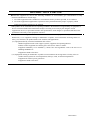
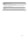
[Typical spectral response]
The lens characteristics and light source characteristics is not reflected in table.
<CSGV90CC3>
1.0
G
B
Relative Responce
0.8
R
0.6
0.4
0.2
0.0
400
450
500
550
600
650
700
650
700
Wave Length[nm]
<CSGX36CC3>
1.0
G
B
Relative Responce
0.8
R
0.6
0.4
0.2
0.0
400
450
500
550
600
Wave Length[nm]
(11/16)
D4153497A
<CSGS20CC2>
1.0
G
B
Relative Responce
0.8
R
0.6
0.4
0.2
0.0
400
450
500
550
600
650
700
650
700
Wave Length[nm]
<CSGU15CC18>
1.0
G
B
0.8
Relative Responce
R
0.6
0.4
0.2
0.0
400
450
500
550
600
Wave Length[nm]
(12/16)
D4153497A
7. Timing chart
Image data outputs of this camera series are transferred with the UDP protocol of Gigabit Ethernet. Timing
numerical value below is prescribed by absolute prerequisite that GiantDragon series use transmission band
without restriction of other node. When there is a node transferring with GiantDragon concerned, it is not same the
numerical value prescribed below.
(1) In the normal shutter mode
Video format: RGB 24 bit, all pixel readout
Expose
GbE bus
Image
Image
Image
T1
TDLY1
T2
T DLY2
T2
Model name
CSGV90CC3
CSGX36CC3
CSGS20CC2
CSGU15CC18
T1 [ms]
0.5
0.5
1.0
1.0
T2 [ms]
7.7
19.3
30.0
46.8
Frame rate [ms]
11.1
27.8
50.0
66.7
* T1 is the maximum value, and T2 (GVSP_FRAME_RATE) is the minimum value.
* Frame rate is maximum speed.
* At the setting the GVSP_SIZE (SCPSx) = 1500 byte / packet.
(T2 is changed by GVSP_SIZE (SCPSx).)
* Set the value that TDLY1 (GVSP_BLOOK_START_DELAY) to satisfy the next numerical formula;
T1 + TDLY1 + T2 >= Frame rate
(13/16)
D4153497A
(2) In the random trigger shutter mode
- When fixed mode (Video format: RGB 24 bit, all pixel readout);
TRIG_IN
T3
Expose
GbE bus
Image
T1 TDLY1
T2
- When pulse width mode (Video format: RGB 24 bit, all pixel readout);
TRIG_IN
T3
T4
Expose
GbE bus
Image
T1 TDLY1
Model name
CSGV90CC3
CSGX36CC3
CSGS20CC2
CSGU15CC18
T3 [us]
0.9
1.5
3.4
1.9
T2
T4 [us]
2.8
25.2
5.1
7.5
* The value of T1 and T2 are the same as the value at the of the normal shutter setting.
(14/16)
D4153497A
8. Guarantee
The term of a guarantee is 12 months after the product delivery.
If by any chance trouble by responsibility of our company occurs before an above period, TELI repairs it free of
charge according to a repair rule of Clause 9.
During terms of a guarantee, when the trouble cause is the case of below, TELI charges the repair costs.
- Troubles and the damages that causes by misuse, unsuitable repair or remodeling.
- Distribution hazards like drops and vibrations after purchase. Troubles and damages by transportation.
- Troubles and damages by fire, natural calamity (earthquake, storm and flood damage, thunderbolt), damages
from salty breeze, gas harm, abnormal voltage.
9. Repair
(1) Condition for repair
Basically, has to return it to our company when the user requests us to repair product.
Beside that, customer should pay these expenses (travel expenses, camera disassembly technology costs) of
both customer and end user. Also customer should pay in themselves costs for return camera to us.
(2) The period of repairing product
- Repair free of charge
Refer to Clause 8.
- Charged repair
Basically, repair period is 7 years after the last production end of products.
(15/16)
D4153497A
10.
Outline Drawing
(16/16)
D4153497A
Head Office : 7-1, 4 chome, Asahigaoka, Hino-shi, Tokyo, 191-0065, Japan
(Overseas Sales Department)
Phone : +81-42-589-8771
Fax
: +81-42-589-8774
URL
: http://www.toshiba-teli.co.jp
Distributor
• This product must be classified for disposal according to the laws of each country and municipal laws.
• Information contained in this document is subject to change without prior notice.
GiantDragon Color model Specifications 2008-01-22 publication
D4153497A