1
DOCUMENT: NBZ0002
INSTRUCTION MANUAL
INSTALLATION - OPERATION - MAINTENANCE
TX SERIES
Low Voltage
Digital Solid State Starter
48 - 1250 A
Issued: 11/04
Manufactured in the USA
SAFETY
IMPORTANT MESSAGES
Read this manual and follow its intructions. Signal words such as DANGER, WARNING
and CAUTION will be followed by important safety information that must be carefully reviewed.
DANGER
Indicates a situation which will result in death, serious injury, and severe property damage if you
do not follow instructions.
WARNING
Means that you might be seriously injured or killed if you do not follow instructions. Severe
property damage might also occur.
CAUTION
Means that you might be injured if you do not follow instructions. Equipment damage might
also occur.
NOTE
Give you helpful information.
Note: The contents of this manual will not become apart of or modify the warranty
policy, the terms of which are set forth at the end of this manual.
READ SAFETY SIGNS
To avoid injury, you must read and follow all safety signs.
Keep the safety signs visible and in good shape. Never remove or cover any safety sign.
DANGER
QUALIFIED OPERATORS ONLY
Only qualified persons are to install, operate, or service this equipment according to all applicable
codes and established safety practices.
A qualified person must:
1)
2)
3)
4)
5)
6)
Carefully read the entire instruction manual.
Be skilled in the installation, construction or operation of the equipment and aware of
the hazards involved.
Be trained and authorized to safely energize, de-energize, clear, ground, lockout and
tag circuits in accordance with established safety practices.
Be trained and authorized to perform the service, maintenance or repair of this equipment.
Be trained in the proper care and use of protective equipment such as rubber gloves,
hard hat, safety glasses, face shield, flash clothing, etc. in accordance with established practices.
Be trained in rendering first aid.
SAFETY
SAFETY CODES
Toshiba motor control is designed and built in accordance with the latest applicable provisions of
NEMA and the National Electrical Code. Installations must comply with all applicable state and local
codes, adhere to all applicable National Electric Code (NFPA 70) standards and instructions provided
in this manual.
HAZARDOUS VOLTAGE will cause severe injury, death, fire, explosion and
property damage.
•
Turn off and lock out Primary and Control Circuit Power before servicing.
•
Keep all panels and covers securely in place.
•
Never Defeat, Modify, or Bypass any Safety Interlocks.
•
Qualified Operators only.
Never attempt to install, operate, maintain or dispose of this equipment until
you have first read and understood all of the relevant product warnings and
user directions that are contained in this Instruction Manual.
WARNING
Use only Toshiba-authorized replacement parts.
This equipment is designed and built in accordance with applicable safety
standards in effect on the date of manufacture. Unauthorized modifications
can result in voiding the warranty, severe injury, death and property
damage. Do not make any modifications to this equipment without
the written approval of Toshiba.
For assistance, address correspondence to:
Toshiba International Corporation
Field Service Department
13131 West Little York Road
Houston, Texas 77041 USA
or call:
(713) 466-0277
(800) 231-1412
(800) 527-1204 (Canada)
Fax:
(713) 466-8773
Please complete the following information for your records and retain with this manual:
Model:
___________________________________
Serial Number:
_____________________________
Date of Installation:
Inspected by:
_________________________
______________________________
Reference Number:
_________________________
© TOSHIBA INTERNATIONAL CORPORATION, 2004
TX
TX Series
Series
Digital Solid State
Soft Starter
48 - 1250A
Installation &
Operation Manual
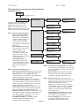
Chapter 1: Introduction ......................................................................................................
1
48 - 1250A
1.1
1.2
1.3
1.4
1.5
General
Specifications
Theory of Operation
General Protection
Thermal Overload Protection
Chapter 2: Installation ....................................................................................................... 8
2.1
2.2
2.3
2.4
2.5
2.6
2.7
2.8
2.9
2.10
2.11
Receiving and Unpacking
Initial Unit Inspection
Location
Mounting & Cleaning
Power Wire Range and Tightening Torque
Dimensions
Power Connections
Control Connections
CPU Board Connections
Communications Board
RTD Board (Optional)
Chapter 3: Start-Up .......................................................................................................... 16
3.1
3.2
3.3
3.4
3.5
Preliminary Start-up Check List
Introduction
Acceleration Adjustments
Deceleration Adjustments
Sequence of Normal Operation
Chapter 4: User Interface and Menu Navigation ............................................................. 20
4.1
4.2
Keypad/Operator Interface
Menu Navigation
Chapter 5: Setpoint Programming .................................................................................. 23
5 .1
5.2
Setpoints Page List
Setpoint Menu
SP.1 Basic Configuration ................................................................................................ 33
SP.2 Starter Configuration ............................................................................................... 34
SP.3 Phase & Ground Settings ....................................................................................... 37
SP.4 Relay Assignment ................................................................................................... 40
SP.5 Relay Configuration ............................................................................................... 42
SP.6 I/O Configuration .................................................................................................... 43
SP.7 Custom Acceleration Curve ................................................................................... 46
SP.8 Overload Curve Configuration ............................................................................... 49
SP.9 RTD Configuration .................................................................................................. 50
SP.10 Set Password ....................................................................................................... 52
SP.11 Communications .................................................................................................... 53
SP.12 System Setpoints .................................................................................................. 54
SP.13 Calibration & Service ............................................................................................ 56
Chapter 6: Metering Pages .............................................................................................. 57
6 .1
Metering Page List
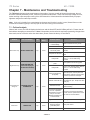
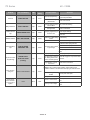
Chapter 7: Maintenance and Troubleshooting/Disposal/Storage .................................. 67
7.1
7.2
7.3
7.4
7.5
7.6
7.7
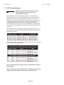
Failure Analysis
SCR Testing Procedure
Replacing SCR devices
Replacing the Main Control Board
Interconnect Drawing
Maintenance Program
Disposal/Storage
Appendix A: Reference Section ....................................................................................... 78
Appendix B: Record of Setpoint Adjustments ................................................................. 81
Warranty Policy ................................................................................................................. 89
TOSHIBA- 95
TX Series
48 - 1250A
TOSHIBA - 96
TX Series
48 - 1250A
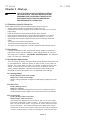
Chapter 1 - Introduction
This chapter is a brief introduction to the TX Series soft starter and describes
product operation and unit features.
1.1 - General
The TX Series is a high-end digitally programmable solid state reduced voltage soft
starter. This heavy duty starter provides reduced voltage, stepless soft starting of
3-phase AC induction motors, protecting mechanical components from excessive
torque stress and electrical systems from the effects of high motor inrush currents.
The TX Series includes advanced motor and load protection features just like those
found in expensive motor protection relays. These include retentive thermal
memory, dynamic reset capacity, true thermal modeling, separate trip curves for
start and run protection, overload alarm, etc. In the case of the TX Series, these
features are built in as standard features, providing a cost effective and reliable
motor starting and protection scheme for your critical motor applications.
The TX Series features an easy to use interface operator for programming and
status indication. It includes a large tactile feedback keypad, LED status indicators and a 2 line x 20 character backlit display using plain English text readout. In
addition to programming the standard parameters such as starting torque, ramp
time, current limit, dual ramp and decel control, other features like programmable
overload trip curves (NEMA/UL Classes 5 - 30), starts-per-hour, time between
starts and coast down/back spin lockout protection can also be programmed for
your specific application needs.
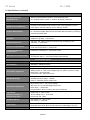
1.2 Specifications
Type of Load
Three phase AC induction motors or synchronous motors
AC Supply Voltage
208 - 600 VAC +10%, 50/60 Hz
HP Ratings
39 - 1250 Amps, 10 - 1125 HP
Unit Overload Capacity
(Percent of motor FLA)
125% - Continuous
500% - 60 seconds
600% - 30 seconds
Power Circuit
6 SCRs
SCR Diode Ratings
(Peak Inverse Voltage)
1600V
Phase Insensitivity
Unit operates with any phase sequence
Transient Voltage Protection
RC snubber dv/dt networks on each phase
Cooling
Convection up to 180A, fan assisted 78 - 120A
Fan ventilated 220 - 1250A
Bypass Contactor
Full horsepower rated contactor included as standard in all Type 12, 3R, 4 & 4X
enclosed units 120A and above.
Ambient Condition Design
Chassis units: 0° to 50 °C (32° to 122°F)
Enclosed units: 0° to 40°C (32° to 104°F)
5 - 95% relative humidity
0 - 3300 ft. (1000m) above sea level without derating
Control
2 or 3 wire 120VAC (customer supplied)
Optional 240VAC control voltage and CPTs are available
Auxiliary Contacts
Approvals
Type/Rating: FORM C (SPDT), rated 5 Amps, 240VAC max. (1200VA)
4 Programmable Relays
UL Listed, Canadian UL (cUL)
TOSHIBA- 1
TX Series
48 - 1250A
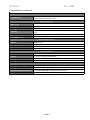
1.2 Specifications (continued)
Advanced Motor Protection
Two Stage Electronic
Overload Curves
Starting: programmable for Class 5 - 30 or locked rotor time.
Run: Programmable for Class 5 - 30 when "At-Speed" is detected.
Overload Reset
Manual (default) or automatic
Retentive Thermal Memory
Overload circuit retains thermal condition of the motor regardless of control
power status. Unit uses real time clock to adjust for off time.
Dynamic Reset Capacity
Overload will not reset until thermal capacity available in the motor is enough
for a successful restart. Starter learns and retains this information by monitoring
previous successful starts.
Phase Current Imbalance
Protection
Imbalance Trip Level: 5 - 30% current between any two phases
Imbalance Trip Delay: 1 -20 seconds
Over Current Protection
(Electronic Shear Pin)
Trip Level: 100 - 300% of motor FLA while running not starting or OFF
Trip Delay: 1 - 20 seconds
Load Loss Trip Protection
Under Current Trip Level: 10 -90 % of motor FLA or OFF
Under Current Trip Delay: 1 - 60 seconds
Coast Down (Back Spin)
Lockout Timer
Coast Down Time Range: 1 - 60 minutes or OFF
Starts-per-hour Lockout Timer
Range: 1 - 6 successful starts per hour
Time between starts: 1 - 60 minutes between start attempts
Programmable Outputs
Type / Rating
Form C (DPDT), Rated 5 amps 240 VAC max, (1200 VA)
Run Indication
Start/Stop or Start/End of Decel
At Speed Indication
At Speed/Stop or At Speed/End of Decel
Acceleration Adjustments
Programmable Ramp Types: Voltage or Current Ramp (VR or CR)
Starting Torque: 0 - 100% of line voltage (VR) or 0 - 600% of motor FLA (CR)
Ramp Time: 1 to 120 seconds
Current Limit: 200 - 600% (VR or CR)
Dual Ramp Settings
4 Options: VR1+VR2; VR1+CR2; CR1+CR2; CR1+VR2
Dual Ramp Control: Ramp 1 = Default
Ramp 2 = selectable via dry contact input
Deceleration Adjustments
Begin Decel Level: 0 - 100% of line voltage
Stop Level: 0 to 1% less than Begin Decel Level
Decel Time: 1 - 60 seconds
Programmable to decel or coast to stop upon overload trip
Jog Settings
(Function selected via
programming input)
Voltage Jog: 5 - 100% or OFF
Time of Voltage Jog: 1 - 20 seconds
Current Jog: 100 - 500%
Kick Start Settings
Kick Voltage: 10 - 100% or OFF
Kick Time: 0.1 - 2 seconds
Fault Display
Shorted SCR, Phase Loss, Shunt Trip, Phase Imbalance Trip, Overload,
Overtemp, Overcurrent, Short Circuit, Load Loss, Undervoltage or Any Trip
Lockout Display
Coast Down Time, Starts Per Hour, Time Between Starts, and Any Lockout
TOSHIBA - 2
TX Series
48 - 1250A
1.2 Specifications (continued)
Event History
Up to 60 Events
Data includes cause of event, time, date, and current for each phase and
ground fault current at time of event
Metering Functions
Motor Load
Percent of FLA
Current Data
A, B, C Phase Current, Avg Current, Ground Fault
Thermal Data
Remaining thermal register; thermal capacity to start
Start Data
Avg Start Time, Avg Start Current, Measured Capacity to start, time since last
start
RTD Data
Temperature readings from up to 12 RTDs (6 stators)
Voltage Metering
KW, KVAR, PF, KWH
Serial Communications
Protocol
Modbus RTU
Signal
RS-485 or RS-422
Network
Up to 247 devices per mode
Functionality
Full operation, status view, and programming via communications port
Operator Interface
LCD Readout
Alpha numeric LCD display
Keypad
8 function keys with tactile feedback
Status Indicators
8 LEDs include Power, Run, Alarm, Trip, Aux Relays
Remote Mount Capability
Up to 1000 feet from chassis (use twisted, shielded wire)
Clock and Memory
Operating Memory
DRAM loaded from EPROM and EEPROM at initialization
Factory Default Storage
Flash EPROM, field replaceable
Customer Settings and Status
Non-volatile EEPROM, no battery backup necessary
Real Time Clock
Lithium ion battery for clock memory only
TOSHIBA- 3
TX Series
48 - 1250A
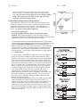
1.3 - Theory of Operation
The power of the TX Series is in the CPU, a microprocessor based
protection and control system for the motor and starter assembly.
The CPU uses Phase Angle Firing of the SCRs to apply a reduced
voltage to the motor, and then slowly and gently increases torque
through control of the voltage and current until the motor accelerates
to full speed. This starting method lowers the starting current of the
motor, reducing electrical stresses on the power system and motor.
It also reduces peak starting torque stresses on both the motor and
load mechanical components, promoting longer service life and less
downtime.
Acceleration: The TX Series comes standard with several methods of
accelerating the motor so that it can be programmed to match almost
any industrial AC motor application.
The factory default setting applies a Voltage Ramp with Current Limit
as this has been proven the most reliable starting method for the vast
majority of applications. Using this starting method, the Initial Torque
setting applies just enough voltage to the motor to cause the motor shaft
to begin to turn. This voltage is then gradually increased over time (as
per the Ramp Time setting) until one of three things happen: the motor
accelerates to full speed, the Ramp Time expires or a Current Limit
setting is reached.
If the motor accelerates to full speed before the ramp time setting has
expired, an automatic Anti-Oscillation feature will override the remaining
ramp time and full voltage will be applied. This will prevent any surging
or pulsation in the motor torque, which might otherwise occur due to the
load not being fully coupled to the motor when operating at reduced
voltage and torque levels.
If the motor has not reached full speed at the end of the ramp time
setting, the current limit setting will proportionally control the maximum
output torque. Feedback sensors in the TX Series provide protection
from a stall condition, an overload condition or excessive acceleration
time.
The Current Limit feature is provided to accommodate installations
where there is limited power available (for example, on-site generator
power or utility lines with limited capacity). The torque is increased
until the motor current reaches the preset Current Limit point and it is
then held at that level. Current Limit overrides the ramp time setting
so if the motor has not accelerated to full speed under the Current
Limit setting, the current remains limited for as long as it takes the
motor to accelerate to full speed.
When the motor reaches full speed and the current drops to running
levels, the TX Series detects an At-Speed condition and will close the
Bypass Contactor (if provided). The Bypass Contactor serves to shunt
power around the SCR stack assemblies to prevent heat build-up
NEMA 12, 3R, 4 and 4X enclosed units due to the slight voltage drop
across the SCRs. At this point, the TX Series has the motor operating at full voltage, just as any other starter would.
TOSHIBA - 4
TX Series
48 - 1250A
Other starting methods available in the TX Series are:
· Current Ramp: uses a closed current feedback PID loop to provide a linear
torque increase up to a Maximum Current level.
· Constant Current: current is immediately increased to the Current Limit point
and held there until the motor reaches full speed.
· Custom Curve: gives the user the ability to plot torque and time points on a
graph. The soft starter will then accelerate the motor following these points.
· Tachometer Feedback Ramp: uses a closed loop speed follower method
monitoring a tachometer input signal from the motor or load shaft. (PENDING)
Deceleration: the TX Series provides the user with the option of having the
load coast to a stop or controlling the deceleration by slowly reducing the voltage
to the motor upon initiating a stop command. The Decel feature is the opposite of DC injection braking in that the motor will actually take longer to
come to a stop than if allowed to coast to a stop. The most common application for the Decel feature is pumping applications where a controlled stop
prevents water hammer and mechanical damage to the system.
1.4 General Protection
Operation of the TX Series can be divided into 4 modes; Ready, Start, Run and
Stop. The CPU provides motor and load protection in all four modes. Additional
details on each protection feature can be found in later chapters.
Ready Mode: In this mode, control and line power are applied and the starter is
ready for a start command. Protection during this mode includes the monitoring of current for leakage through multiple shorted SCRs. Other protection
features in effect are:
·
·
·
·
·
Starter Temperature
Shorted SCR
Phase Reversal (if enabled)
Line Frequency Trip Window
External Input Faults
Note: The “Programming Mode” can only be entered from the Ready Mode.
During programming, all protection features and start command are disabled.
Start Mode: These additional protection functions are enabled when the soft
starter receives a valid Start command:
·
·
·
·
·
·
·
·
·
·
Phase Reversal (if enabled)
Start Curve
Acceleration Timer
Phase Imbalance
Short Circuit / Load Pre-check (Toe-in-the-Water)
Ground Fault
External Input Faults
Accumulated Starting FLA Units (I2t Protection)
Overload Protection
Thermal Capacity
Note: Shorted SCR and Shunt Trip protection are no longer in effect once the
soft starter goes into the Start Mode.
TOSHIBA- 5
TX Series
48 - 1250A
Run Mode: The soft starter enters the Run Mode when it reaches full output
voltage and the motor current drops below the FLA setting (motor nameplate
FLA plus service factor) for a predetermined period of time. During the Run
Mode these additional protection features are enabled:
·
·
·
·
·
Running Overload Curve
Phase Loss
Under Current / Load Loss
Over Current / Electronic Shear Pin
External Input Faults
Stop Mode: Once a Stop command has been given, the TX Series protection features change depending on which Stop Mode is selected.
· Decel Mode: retains all protection features of the Run Mode. At the end of
Decel, the motor will be stopped and the protection features change as
indicated below.
· Coast-To-Stop Mode: power is immediately removed from the motor and the
soft starter returns to the Ready Mode. Additional protection features activated
when the stop command is given include:
·
·
·
·
Coast-Down / Back Spin Timer
Starts-per-Hour
Time Between Starts
External Input Faults
1.5 Thermal Overload Protection
The TX Series plays an important role in the protection of your motor in that it
monitors the motor for excessive thermal conditions due to starting, running or even
ambient conditions. The TX Series has a Dynamic Thermal Register system in
the CPU that provides a mathematical representation of the thermal state of the
motor. This thermal state information is kept in memory and is monitored for
excesses in both value and rate of change. Input is derived from current
imbalances and (optional) RTD measurements making it dynamic to all processes
involving the motor. The TX Series monitors these conditions separately during
Start and Run modes to provide proper thermal overload protection at all times.
Start Mode overload protection is selectable using one of three methods:
· Basic Protection: I2t data is accumulated and plotted based on an Overload
Curve selected in programming. This is programmed per NEMA Class 5-30
standard curves and is based on the Locked Rotor Current (from the motor
nameplate) as programmed into the soft starter.
· Measured Start Capacity: the user enters a measured amount of thermal
capacity from a pre-selected successful start as a setpoint to the Thermal
Register for the soft starter to follow.
· Learned Curve Protection: the user sets the soft starter to the “LEARN” mode
and starts the motor under normal starting conditions. The CPU then
samples and records 100 data points during the start curve, analyzes them
and creates a graphical representation in memory. The soft starter is then
switched to Curve Follow protection mode and monitors motor performance
against this curve. This feature is especially useful in initial commissioning
tests to record a base line performance sample (in this case, it is not
necessarily used for motor protection).
TOSHIBA - 6
TX Series
48 - 1250A
Run Mode overload protection is initiated when the TX Series determines
that the motor is At-Speed. Overload Protection is initiated when the motor
RMS current rises above a “pick-up point” (as determined by the motor
nameplate FLA and service factor). Run mode protection is provided by the
CPU monitoring the Dynamic Thermal Register. Data for the Dynamic
Thermal Register is accumulated from I2t calculations and cooling rates. A
trip occurs when the register reaches 100% as determined by the selected
Overload Protection Curve (NEMA Class 5-30 standard curves) and is based
on the programmed Locked Rotor Current indicated on the motor nameplate.
The Dynamic Thermal Register is altered, or “biased”, by the following conditions:
· Current Imbalance: will bias the register higher to add protection from
additional motor heating during a current imbalance condition.
· Normal Cooling: provided when the motor current drops below the pick-up
point or the motor is off line. The cooling rate is lower for motors that are offline (such as after a trip) since cooling fans are also inoperative.
· RTD Input: (requires the optional RTD monitor card): will bias the register in
either direction based on real-time input of the motor, bearing and even
ambient temperature conditions.
· Dynamic Reset is another feature that adds reliability and consistency to the
performance of the TX Series soft starter. If a motor overload condition
occurs and the soft starter trips, it cannot be reset until sufficient cool down
time has elapsed. This cool down time is determined by the thermal state of
the motor when it tripped (i.e. hot motors cool more quickly due to additional
convection). The cool down time is also biased by RTD measurements when
used.
Retentive Thermal Memory provides continuous overload protection and real
time reset even if power is lost. Upon restoration of power, the TX Series will
read the Real Time Clock and restore the thermal register to what it should be
given the elapsed time.
· Learned Reset Capacity is a feature that is unique to the TX Series. By
sampling the amount of thermal capacity used in the previous three successful
starts, the TX Series will not allow a reset until a sufficient amount of
thermal capacity has been regained in the motor. This prevents nuisance
tripping and insures that unsuccessful start attempts (which would otherwise
use up the starts-per-hour capacity of the motor) are not allowed.
TOSHIBA- 7
TX Series
48 - 1250A
Chapter 2 - Installation
2.1 Receiving and Unpacking
Upon receipt of the unit:
• Carefully unpack the unit and inspect it for any shipping damage.
Report any damage immediately and file a claim with the freight
carrier within 15 days of receipt.
• Verify that the model number on your unit matches your purchase
order.
• Confirm that the ratings label on the unit matches or is greater than
the motor’s HP and current rating.
2.2 Initial Unit Inspection
• Make a complete visual check of the unit for damage which may have
occurred during shipping and handling. Do not attempt to continue
installation or start up the unit if it is damaged.
• Check for loose mechanical assemblies or broken wires which may
have occurred during transportation or handling. Loose electrical
connections will increase resistance and cause the unit to function
improperly.
• Prior to beginning the installation, verify that the motor and TX unit
are rated for the proper amperage and voltage.
2.3 Location
The proper location of the unit is an important factor in achieving the
unit’s specified performance and normal operation lifetime. The unit
should always be installed in an area where the following conditions
exist:
• Ambient Operating Temperature: 0° C to 50° C (32° F to 122° F)
(Optional space heaters can be provided for operation in ambient
temperature to -20° C.)
• Protected from rain and moisture.
• Humidity: 5% to 95% non-condensing.
• Free from metallic particles, conductive dust and corrosive gas.
• Free from excess vibration (below 0.5G)
• Open panel units must be mounted in the appropriate type of
enclosure. Enclosure size and type must be suitable to dissipate
heat generated by the soft starter. Contact factory for assistance in
sizing the enclosure.
WARNING
Do not service equipment with voltage applied!
The unit can be the source of fatal electrical
shocks! To avoid shock hazard, disconnect
main power and control power before working
on the unit. Warning labels must be attached
to terminals, enclosure and control panel to
meet local codes.
2.4 Mounting and Cleaning
When drilling or punching holes in the enclosure, cover the electrical
assembly to prevent metal filings from becoming lodged in areas which
can cause clearance reduction or actually short out electronics. After
work is completed, thoroughly clean the area and reinspect the unit for
foreign material. Make sure there is sufficient clearance (six inches)
all around the unit for cooling, wiring and maintenance purposes. To
maximize effective air flow and cooling, the unit must be installed with
its heat sink ribs oriented vertically and running parallel to the mounting
surface.
TOSHIBA - 8
TX Series
48 - 1250A
Remove all sources of power before cleaning the unit!
WARNING
In dirty or contaminated atmospheres the unit should be cleaned on a regular
basis to ensure proper cooling. Do not use any chemicals to clean the unit. To
remove surface dust use 80 to 100 psi, clean, dry compressed air only. A three
inch, high quality, dry paint brush is helpful to loosen up the dust prior to using
compressed air on the unit.
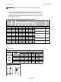
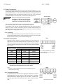
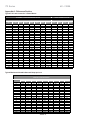
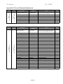
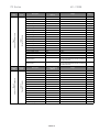
2.5 Power Terminal Wire Range and Tightening Torque
Ma x HP
kW
Mode l
Num be r
Ma x
Am ps
208V
230V
480V
600V
230V
400V
W ire
Ra nge
Torque
lbs/in
TX005
48
10
15
30
40
11
22
#18 - #4
20
TX006
78
20
25
50
60
22
37
#14 - #2
50
TX007
120
30
40
75
100
30
55
TX008
180
50
60
125
150
55
90
#6 - 250 kcmil
325
TX009
220
60
75
150
200
TX010
288
75
100
200
250
(2) #6 - 600 kcmil
375
TX011
414
125
150
300
350
TX012
476
-
-
350
400
132
(2) #2 - 600 kcmil
375
TX013
550
150
200
400
500
160
200
(3) #2 - 600 kcmil
375
(4) #2 - 600 kcmil
375
TX014
718
200
250
500
600
TX015
1006
300
350
700
800
TX016
1150
350
400
800
900
TX017
1250
450
500
1000
1125
110
75
132
200
250
315
400
Note: All wiring must be sized according to NEC standards
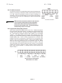
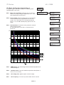
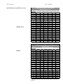
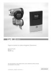
2.6 Dimensions
TX DIMENSIONS
Enclosure
Model
Number
PANEL
(OPEN
CHASSIS
TYPE)
TX005 to TX007
TX008
TX009 to TX010
TX011 to TX013
TX014 to TX015
TX016 to TX017
Overall Dimensions
A
B
C
16.5
10
10
20
20.1
12
27
20.1
11.2
29.5
20.1
11.5
45
33
12.8
33
33
15.2
Mounting Dimensions
D
E
F
15.9
9
0.28
18.5
17.5
0.44
25.5
17.5
0.44
25.5
17.5
0.44
43.3
31.3
0.44
31.2
31.2
0.44
B
F
C
D
E
TOSHIBA- 9
TX Series
48 - 1250A
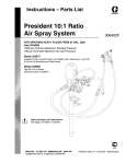
2.7 Power Connections
Connect appropriate power lines to the unit input terminals marked L1, L2, L3.
Avoid routing power wires near the control board. Connect the motor leads to the
unit terminals marked T1, T2, T3. Refer to NEC standards for wire length and sizing.
Never interchange input and output connections to the unit. This could cause
excessive voltage in the control logic circuit and may damage the unit.
TX Series Unit
WARNING
Never connect power factor correction
capacitors on the load side of the unit.
The SCRs will be seriously damaged if
capacitors are located on the load side.
The unit must be tested with a motor or other test load connected
to the load side of the unit. (A load bank can be used if a motor is
not available). Note that line voltage will appear across the output terminals if
there is no motor or load connected to the unit. In areas where lightning is a
significant problem, station-type air gap lightning arrestors should be considered
and utilized on the input power source.
Power Connections
2.7.1 Grounding
Connect the ground cable to the ground terminal as labeled on the unit. Refer
to the National Electrical Code for the proper ground wire sizing and be sure
that the ground connector is connected to earth ground.
TB4
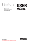
2.8 Control Connections
Separate 120Vac supply is required (240Vac for 380V and 415V
applications). The control voltage should be connected to pins 1 and 6 of
TB4 on the power board. This control voltage must be customer supplied,
unless an optional control power transformer (See chart) has been supplied
with the unit.
TX Model
Recommended Transformer Sizes
Panel
NEMA Type 1
NEMA Type 12/3R/4
TX008
50 VA
100 VA
250 VA*
TX009
50 VA
100 VA
500 VA*
TX010
250 VA
250 VA
500 VA*
TX011 to TX013
250 VA
250 VA
750 VA*
TX014
500 VA
500 VA
1 KVA*
TX015 to TX016
500 VA
750 VA
1.5 KVA*
TX017
500 VA
750 VA
1.5 KVA*
Control
Power
Source
Control
Power
Return
Unit comes standard with 120Vac
control. Order 240Vac control as an
option if required.
* Transformer size is adequate to power built-in bypass contactors on these models.
Recommended Transformer Sizes for Control Power
Note:
1. If power is used for additional accessory items (Lights, fans, etc.)
contact factory for sizing.
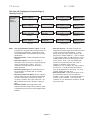
2.8.1 Three-Wire Connection
For standard 3-wire control connect 120Vac (or 240Vac for 415V and
380V applications) to pins 1 and 6 of TB4. Connect N.C. (normally
closed) stop button between pins 3 and 4 of TB4. Connect N.O.
(normally open) start button between pins 4 and 5 of terminal block
TB4.
TOSHIBA - 10
Three-Wire Connection
TX Series
48 - 1250A
2.8.2 Two-Wire Connection
An alternate connection for unattended operation replaces start/stop push
buttons by connecting a maintained contact closure between pins 3 and
5 on TB4. When the maintained contact is used for start/stop it is
necessary to set the overload setpoint to the manual reset position.
This will prevent the motor from restarting if the thermal overload trips
and then cools off.
Two-Wire Connection
WARNING
When two-wire connection method is used, the start
circuit must be interlocked to prevent automatic
restart when either of the two protective devices
(overload or thermostat) reset. Thermostats always
automatically reset on cool down.
2.8.3 Programmable Relays/Relay Contacts
All the relay contacts are FORM C (Com, N.O., N.C.). Toshiba recommends
fusing all contacts with external fuses. The TX has four programmable relays
on TB3 on the power board. The relays are rated for 240Vac, 5 A and 1200
VA. These relays can respond to either a fault condition or an up-to-speed
condition. In the TX all tripping functions have been assigned to the TRIP
(AUX1) relay, and all alarm (warning) condition has been configured to the
ALARM (AUX2) relay. AUX 3 is factory programmed for a SHUNT TRIP
indication and can be connected to a shunt trip coil on an incoming circuit
breaker or open an input isolation contactor. AUX4 is the AT SPEED contact.
When the motor has reached the end of its acceleration ramp, the TX will
wait until the AT SPEED programmed time delay has expired. Then, the
relay will energize until a stop command has been received. The AT SPEED
contact can be used to operate a bypass contactor (used for shorting the
load current around the SCRs. To change AUX3 or AUX4 functions, see
Setpoint Page 4.
Relay Contacts on Power Board
Rated 240Vac, 5A, 1200VA
TOSHIBA- 11
TX Series
48 - 1250A
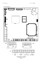
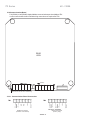
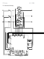
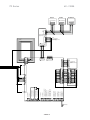
2.8.4 Power Board
2.8.4a Power Board Connections
TB4
TB4
Two-Wire Control Connection
Three-Wire Control Connection
Relay Contacts on Power Board
Rated 240Vac, 5A, 1200VA
TOSHIBA - 12
TX Series
48 - 1250A
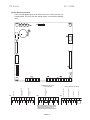
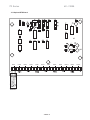
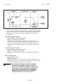
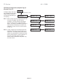
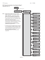
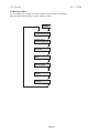
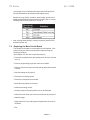
2.9 CPU Board Connections
There are eight digital inputs on the CPU board. Four of the inputs are user
programmable. There are also two analog outputs, a tachometer feedback
input.
20
20
1
2
+
-
3
4
5
+
-
6
7
8
+
-
1
2
3
4
+
-
5
6
7
8
Note: Install program jumper to enable
setpoint programming. Jumper must be
removed after programming or for
prolonged storage to preserve settings.
TOSHIBA- 13
Thermostat
Dual Ramp
TB3
External Input #2
External Input #1
TB2
9
Factory wired. Do not change
Program Enable
Input
TB1
Analog Output #2
4 - 20 mA
Tach Input
Analog Output #1
4 - 20 mA
Contact factory for remote
reset connections
1
2
3
4
5
6
+
-
+
-
+
-
7
8
+
-
TX Series
48 - 1250A
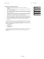
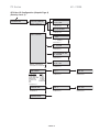
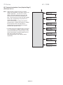
2.10 Communications Board
Full (RS422) or half (RS485) duplex Modbus communications port is available at TB1
on the communications board. No field wiring connections are required for TB2.
REAR
VIEW
(RS485)
(RS422)
Note: Remove for last unit in modbus string
2.10.1 Communication Board Connections
TB1
TB2
RS485 Connections
(Customer Connections)
RS422 Connections
(Factory Only)
TOSHIBA - 14
TX Series
48 - 1250A
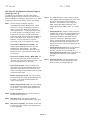
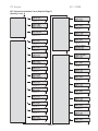
2.11 Optional RTD Board
RTD2
RTD3
RTD4
RTD5
RTD6
RTD7
Signal
Power
Compensation
Shield
RTD1
RTD
Typical RTD
Installation
TOSHIBA- 15
RTD8
RTD9
RTD10
RTD11
RTD12
TX Series
48 - 1250A
Chapter 3 - Start-up
WARNING
THE TX UNIT DEALS WITH POTENTIALLY LETHAL
VOLTAGE LEVELS. YOU MUST BE CERTAIN THAT
PERSONNEL ARE THOROUGHLY TRAINED IN THE
APPLICABLE SAFETY PRECAUTIONS BEFORE
PROCEEDING WITH THIS SECTION!
3.1 Preliminary Start-Up Check List
Please make the following checks before applying power to the unit:
•
Supply voltage matches the rated supply voltage of the unit.
•
Horsepower and current ratings of the motor and unit match or the unit has a
higher rating.
•
Initial ramp time and torque adjustments have been checked.
•
Power lines are attached to the unit input terminals marked L1, L2 and L3.
•
Motor leads are connected to the lower terminals marked T1, T2 and T3.
•
Appropriate control power is applied and/or control connections have been
made.
•
The motor’s FLA has been programmed.
•
The thermal overload parameters are properly set.
•
The motor area and equipment are clear of people and parts before start-up.
3.2 Introduction
It is best to operate the motor at its full load starting condition to achieve the
proper time, torque and ramp settings. Initial settings are set to accommodate most motor conditions. TRY INITIAL SETTINGS FIRST. See Setpoints
Page 2 to make any adjustments.
3.3 Acceleration Adjustments
The unit is set at the factory with typical starting characteristics that perform well
in most applications. When the system is ready to start, try the initial unit
settings. If the motor does not come up to speed, increase the current limit
setting. If the motor does not start to turn as soon as desired, raise the
starting voltage adjustment. Adjustment description and procedures are
described as follows (See section 4.5.2 for additional Accel settings):
3.3.1 Starting Voltage
Factory Setting = 20% of line voltage
Range = 0% - 100% of line voltage
Starting voltage adjustment changes the initial starting voltage level to the
motor.
3.3.2 Ramp Time
Factory Setting = 10 sec.
Range = 0 - 120 sec.
Ramp time adjustment changes the amount of time it takes to reach the
current limit point or full voltage if the current limit point was not reached.
3.3.3 Current Limit
Factory Setting = 350% of unit FLA
Range = 200% - 600% of unit FLA
The current limit adjustment is factory set for 350% of the unit’s rating.
The range of adjustment is 200% to 600%. The main function of current
limit is to cap the peak current. It may also be used to extend the ramping time if required. The interaction between the voltage ramp and the
current limit will allow the soft start to ramp the motor until the maximum
current is reached and the current limit will hold the current at that level.
TOSHIBA - 16
TX Series
48 - 1250A
The current limit must be set high enough to allow the motor to
reach full speed. The factory setting of 350% is a good starting
point. Do not set the current limit too low on variable starting
loads. This could cause the motor to stall and eventually
cause the overload protection to trip.
3.4 Deceleration Adjustments (Pump Control)
Decel extends the stopping time on loads that would otherwise stop
too quickly if allowed to coast to stop. Decel control provides smooth
deceleration until the load comes to a stop. Three adjustments
optimize the deceleration curve to meet the most demanding requirements. Try factory settings before adjusting.
Deceleration Applications
The unit is shipped from the factory with the decel feature
disabled. Apply power and adjust the soft start before enabling or
modifying the deceleration adjustments. Both acceleration and deceleration
adjustments should be made under normal load conditions.
The deceleration feature provides a slow decrease in the output voltage,
accomplishing a gentle decrease in motor torque during the stopping mode.
This is the OPPOSITE OF BRAKING in that it will take longer to
come to a stop than if the starter were just turned off. The primary use
of this function is to reduce the sudden changes in pressure that are
associated with “Water Hammer” and slamming of check valves with
centrifugal pumps. Decel control in pump applications is often referred
to as Pump Control.
In a pump system, liquid is being pushed uphill. The force exerted by
gravity on the column of liquid as it goes up hill is called the “Head
Pressure” in the system. The pump is sized to provide enough Output
Pressure to overcome the Head Pressure and move the fluid up the
pipe. When the pump is turned off, the Output Pressure rapidly drops
to zero and the Head Pressure takes over to send the fluid back down
the hill. A “Check Valve” is used somewhere in the system to prevent
this (if necessary) by only allowing the liquid to flow in one direction.
The kinetic energy in that moving fluid is suddenly trapped when the
valve slams closed. Since fluids can’t compress, that energy is
transformed into a “Shock Wave” that travels through the piping
system looking for an outlet in which it dissipates. The sound of that
shock wave is referred to as “Water Hammer”. The energy in that
shock wave can be extremely damaging to pipes, fittings, flanges,
seals and mounting systems.
By using the Soft Stop/Deceleration feature of the TX, the pump output
torque is gradually and gently reduced, which slowly reduces the
pressure in the pipe. When the Output Pressure is just slightly lower
than the Head Pressure, the flow slowly reverses and closes the
Check Valve. By this time there is very little energy left in the moving
fluid and the Shock Wave is avoided. When the output voltage to the
motor is low enough to no longer be needed, the TX will end the Decel
cycle and turn itself off.
TOSHIBA- 17
TX Series
48 - 1250A
Another common application for decel control is on material handling conveyors as a means to prevent sudden stops that may cause products to fall over
or to bump into one another. In overhead crane applications, soft stopping of
the Bridge or Trolley can prevent loads from beginning to over swing on
sudden stops.
3.4.1 Start Deceleration Voltage
Factory Setting = 60% of line voltage
Range = 0% - 100% of line voltage
The step down voltage adjustment eliminates the dead band in the
deceleration mode that is experienced while the voltage drops to a level
where the motor deceleration is responsive to decreased voltage. This
feature allows for an instantaneous drop in voltage when deceleration is
initiated.
3.4.2 Stop Deceleration Voltage
Factory Setting = 20% of line voltage
Range = 0% - 100% of line voltage
The stop voltage level setpoint is where the deceleration voltage drops
to zero.
3.4.3 Deceleration Time
Factory Setting = 5 sec.
Range = 0 - 60 sec.
The deceleration ramp time adjusts the time it takes to reach the stop
voltage level set point. The unit should be restarted and stopped to verify
that the desired deceleration time has been achieved.
WARNING
DO NOT EXCEED THE MOTOR MANUFACTURER’S
RECOMMENDED NUMBER OF STARTS PER HOUR.
WHEN CALCULATING THE NUMBER OF STARTS PER
HOUR, A DECEL CURVE SHOULD BE COUNTED AS A
START CURVE. FOR EXAMPLE: RECOMMENDED
NUMBER OF STARTS PER HOUR = 6, ALLOWABLE
STARTS WITH DECEL CYCLE PER HOUR = 3.
TOSHIBA - 18
TX Series
48 - 1250A
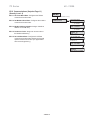
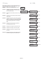
3.5 Sequence of Normal Operation
•
•
•
•
•
•
Apply control power and check that the “Power” LED comes on.
(Display 1)
Apply three phase power to the unit. The motor should run only when the
start command is applied.
Apply the start command. (Display 2). The RUN LED will be lit. (Display 3)
The AUX3 LEDs will be lit. If the motor does not enter run mode in the set
time, a trip will occur.
The POWER, RUN, AUX3 LEDs will be lit, indicating that the contact has
energized. IA, IB, IC will display the current setting for Phase A, Phase B,
and Phase C and the G/F indicates ground fault. (Display 4)
When the motor reaches full speed, the “AUX4” LED (At Speed) will be lit.
If the motor decelerates, or stops, during the acceleration period, hit the
stop button immediately and open the disconnect line. If the unit does not
follow this operational sequence, please refer to the Troubleshooting
Chapter.
It is best to operate the motor at its full load starting condition to achieve the
proper time, torque and ramp settings. Initial settings are set to accommodate
most motor conditions. TRY INITIAL SETTINGS FIRST. See Setpoint Page 2
to make any adjustments.
•
Initial Voltage
•
Soft Start Curve
•
Current Limit
•
Acceleration Time
If decel is enabled, the following parameters for Deceleration Time, Start Decel
Voltage (see SP2) and Stop Decel Voltage (see SP2) must also be programmed.
TOSHIBA- 19
1.
MOTOR STOPPED
READY TO START
2.
MOTOR STARTING
00 X FLA
3.
OVERLOAD ALARM
TIME TO TRIP: XXX SECS.
4.
IA: _ _ _ IB: _ _ _
IC: _ _ _ G/F: _ _ _
TX Series
48 - 1250A
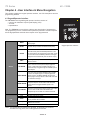
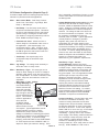
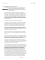
Chapter 4 - User Interface & Menu Navigation
This chapter explains the keypad operator interface, the LCD descriptions and the
programming features
4.1 Keypad/Operator Interface
The TX Series user keypad/keypad operator interface consists of:
• 2 row by 20 characters Liquid Crystal Display (LCD)
• 12 LEDs
• 8 pushbuttons
Note: The TX Series is menu driven and there are three levels of programming.
The programming for two of these levels is password protected. Level two requires
a three digit password and level three requires a four digit password.
MENU
Toggle between the menu selection for metering and
setpoint pages.
RESET
W ill clear the trip indicator and release the trip relay.
ENTER
In the edit mode, press the ENTER pushbutton so the
unit will accept the new programming information. W hen
not in the edit mode, the ENTER pushbutton will toggle
through the event indicator list (such as alarms or trips)
Keypad Operator Interface
HELP
Button
UP ARROW
Provides general help information about a specific
setpoint or action.
W ill scroll up through the setpoint and metering menu
page. It will scroll to the top of the setpoint page or a
section. In edit mode it will increase a setpoint in an
incremental step or toggle through the available options
in the setpoint.
In the main menu the RIGHT ARROW button provides
access to the setpoint page. For setpoint pages with
RIGHT ARROW multiple columns, the RIGHT ARROW will scroll the
setpoint page to the right. W hen in edit mode it will shift
one character to the right.
W ill scroll down through the setpoint pages and down
through the setpoints. In edit mode, it will decrement
DOWN ARROW
through values and toggle available options in the
setpoint.
LEFT ARROW
Power
Run
LED
Alarm
Trip
AUX 1-4
W ill move to the left through setpoint pages with multiple
columns. When in edit mode it will become the
backspace key and will shift one character to the left.
Indicates control power is present
Indicates unit/motor is running
Lights in conjunction with AUX 2 to indicate event or
warn of possible critical condition.
Lights in conjunction with AUX 1 to indicate a critical
condition has occurred.
Auxilary relays
Note: The directional arrow buttons are sensitive. In edit mode, if the buttons
are held for a long period, the scrolling speed will increase.
TOSHIBA - 20
TX Series
48 - 1250A
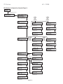
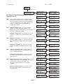
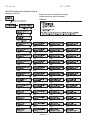
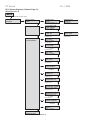
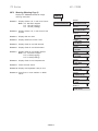
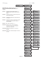
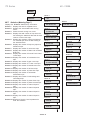
4.2 Menu Navigation
MENU
(1)
PAGE 1 BASIC
CONFIGURATION
Notes:
1. The MENU keys allow you to toggle the screens between the Setpoint Menu and
the Metering Menu. Simply use the arrow keys to get to the different screens
within each menu.
Example: To access Setpoint Page 3: PHASE & GROUND SETTINGS, press
the MENU key once and the DOWN ARROW two times.
2. Levels 1, 2 and 3 indicate password protection levels for these setpoint pages.
LEVEL 1
PAGE 2 STARTER
CONFIGURATION
PAGE 3
PHASE &
GROUND SETTINGS
PAGE 4 RELAY
ASSIGNMENT
LEVEL 2
PAGE 5 RELAY
CONFIGURATION
PAGE 6
USER I/O
CONFIGURATION
PAGE 7
CUSTOM
ACCELERATION CURVE
PAGE 8 OVERLOAD
CURVE CONFIGURATION
PAGE 9 RTD
CONFIGURATION
LEVEL 3
PAGE 10 SECURITY
SET PASSWORD
PAGE 11
COMMUNICATIONS
PAGE 12
SYSTEM
SETPOINTS
FACTORY
LEVEL
PAGE 13 CALIBRATION
& SERVICE
TOSHIBA- 21
TX Series
48 - 1250A
4.2.1 Password Access
Screens in Level 1 of the setpoint menu can be changed without password
access because they list basic motor information. Screens in Levels 2
and 3 require passwords because they provide more in-depth protection
and control of the TX Series unit. The password in Levels 2 and 3 can be
changed by the user.
NOTE: Setpoints can only be changed when the motor is in Stop/
Ready Mode! The TX will not allow a start if it is still in the
Edit Mode. When the unit is in the Edit Mode, a “*” is in the
top right corner of the display.
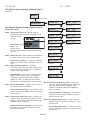
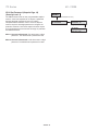
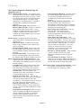
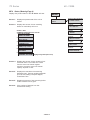
4.2.2 Changing Setpoints
Example 1: Changing Motor FLA
A. Press MENU button to display Setpoint Page 1, Basic Configuration
B. Press the RIGHT ARROW you will view the screen Motor Full Load
Amps.
C. Press the ENTER button for edit mode. Note the asterisk (*) in the
top right corner of the LCD screen that indicates Edit Mode.
D. To change the value, select the UP ARROW or DOWN ARROW.
E. To accept the new value, press the ENTER button. The unit will
accept the changes and will leave the edit mode. Note the * is no
longer in the top right corner of the LCD Display.
MENU
PAGE 1 BASIC
CONFIGURATION
MOTOR FULL LOAD AMPS
: 140 AMPS
ENTER
2x
MOTOR FULL LOAD AMP*
: 142 AMPS
ENTER
MOTOR FULL LOAD AMP
: 142 AMPS
TOSHIBA - 22
TX Series
48 - 1250A
Chapter 5 - Setpoint Programming
The TX Series has twelve programmable setpoint pages which define the motor
data, ramp curves, protection, I/O configuration and communications. In Section 5.1,
the setpoint pages are outlined in chart form. In Section 5.2 the setpoint pages are
illustrated and defined for easy navigation and programming. Note: Setpoints can
only be changed when the starter is in the Ready Mode. Also the soft start will not
start when it is in programming mode.
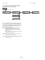
5.1 Setpoints Page List
The following charts list each Setpoint Page and the programmable functions within
that page. The applicable section of the manual is also referenced.
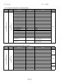
5.1.1 Basic Configuration (Setpoint Page 1)
Security
Level
Level 1
No Passowrd Required
Page 1
Basic Configuration
Setpoint
Page
Factory Setting
Default
Description
Range
Section
Motor Full Load Amps (FLA)
Model dependent
50 - 100% of Unit Max Current Rating (Model
and Service Factor dependent)
Service Factor
1.15
1.00 – 1.3
SP1.2
Overload Class
10
O/L Class 5-30
SP1.3
NEMA Design
B
A-F
SP1.4
Insulation Class
B
A, B, C, E, F, H, K, N, S
SP1.5
Line Voltage
480
208 to 600V
SP1.6
Line Frequency
60
50 or 60 HZ
SP1.7
SP1.1
5.1.2 Starter Configuration (Setpoint Page 2)
Security
Level
Level 1
No Passowrd Required
Page 2
Starter Configuration
Setpoint
Page
Description
Factory Setting
Default
Range
Section
Start Control Mode
Start Ramp 1
Jog, Start Ramp 1, Start Ramp 2, Custom
Accel Curve, Start Disabled, Dual Ramp
SP2.1
Jog Voltage
Off
5-75%, Off
SP2.2
Start Ramp #1 Type
Voltage
Current, Voltage, Off
Initial Voltage #1
20%
0-100%
Ramp Time #1
10 sec
0-120 sec
Current Limit #1
350% FLA
200-600 %
Initial Current #1
200% FLA
0-300%
Ramp Time #1
10 sec
0-120 sec
Maximum Current #1
350% FLA
200-600 %
Start Ramp #2 Type
Off
Current, Voltage, Off
Initial Voltage #2
60%
0-100 %
Ramp Time #2
10 sec
0-120 sec
Current Limit #2
350 % FLA
200-600 %
Initial Current #2
200% FLA
0-600 %
Ramp Time #2
10 sec
0-120 sec
Maximum Current #2
350% FLA
200-600 %
Kick Start Type
Off
Voltage or Off
SP2.3
SP2.4
SP2.5
Kick Start Voltage
65%
10-100 %
Kick Start Time
0.50 sec
0.10-2.00
Deceleration
Disabled
Enabled or Disabled
Start Deceleration Voltage
60%
0-100 %
Stop Deceleration Voltage
30%
0-59 %
Deceleration Time
5 sec
1-60 sec
Timed Output Time
Off
1-1000 sec, Off
SP2.7
Run Delay Time
1 Sec
1-30 sec, Off
SP2.8
At Speed Delay Time
1 Sec
1-30 sec, Off
SP2.9
Bypass Pull-in Current
100% FLA
90 - 300%
SP2.10
TOSHIBA- 23
SP2.6
TX Series
48 - 1250A
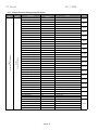
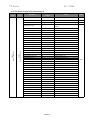
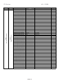
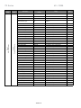
5.1.3 Phase and Ground Settings (Setpoint Page 3)
Security
Level
Level 2
Password Protection
Page 3
Phase and Ground Settings
Setpoint
Page
Imbalance Alarm Level
Factory Setting
Default
15% FLA
5-30 %, Off
Imbalance Alarm Delay
1.5 sec
1.0-20.0 sec
Imbalance Trip Level
20%
5-30 %, Off
Imbalance Trip Delay
2.0 sec
1.0-20.0 sec
Undercurrent Alarm Level
Off
10-90 %, Off
Undercurrent Alarm Delay
2.0 sec
1.0-60.0 sec
Overcurrent Alarm Level
Off
100-300 %, Off
Overcurrent Alarm Delay
2.0 sec
1.0-20.0 sec
Description
Range
Overcurrent Trip Level
Off
100-300 %, Off
Overcurrent Trip Delay
2.0 sec
1.0-20.0 sec
Phase Loss Trip
Disabled
Enabled or Disabled
Phase Loss Trip Delay
0.1 sec
0-20.0 sec
Phase Rotation Detection
Enabled
Enabled Only
Phase Rotation
ABC
ABC
Ground Fault Alarm Level
Off
5-90 %, Off
Ground Fault Alarm Delay
0.1 sec
0.1-20.0 sec
Ground Fault Loset Trip Level
Off
5-90 %, Off
Ground Fault Loset Trip Delay
0.5 sec
0.1-20 sec
Ground Fault Hiset Trip Level
Off
5-90 %, Off
Ground Fault Hiset Trip Delay
0.008 sec
0.008-0.250 sec
Overvoltage Alarm Level
Off
5 -30%, Off
Overvoltage Alarm Delay
1.0 sec
1.0-30.0 sec
Overvoltage Trip Level
Off
5-30%, Off
Overvoltage Trip Delay
2.0 sec
1.0-30.0 sec
Undervoltage Alarm Level
Off
5-30%, Off
Undervoltage Alarm Delay
1.0 sec
1.0-30.0 sec
Undervoltage Trip Level
Off
5-30%, Off
Undervoltage Trip Delay
2.0 sec
1.0-30.0 sec
Line Frequency Trip Window
Disabled
0-6 Hz, Disabled
Line Frequency Trip Delay
1.0 sec
1.0-20.0 sec
P/F Lead P/F Alarm
Off
0.1-1.00, Off
P/F Lead Alarm Delay
1.0 sec
1-120 sec
P/F Lead P/F Trip
Off
.01-1.00, Off
P/F Lead Trip Delay
1.0 sec
1-120 sec
P/F Lag P/F Alarm
Off
.01-1.00, Off
P/F Lag Alarm Delay
1.0 sec
1-120 sec
P/F Lag P/F Trip
Off
.01-1.00, Off
P/F Lag Trip Delay
1.0 sec
1-120 sec
Power Demand Period
10 min
1 - 60 min
KW Demand Alarm Pickup
Off KW
Off, 1-100000
KVA Demand Alarm Pickup
Off KVA
Off, 1-100000
KVAR Demand Alarm Pickup
Off KVAR
Off, 1-100000
Amps Demand Alarm Pickup
Off Amps
Off, 1-100000
TOSHIBA - 24
Section
SP3.1
SP3.2
SP3.3
SP3.4
SP3.5
SP3.6
SP3.7
SP3.8
SP3.9
SP3.10
SP3.11
SP3.12
SP3.13
SP3.14
SP3.15
SP3.16
SP3.17
SP3.18
SP3.19
SP3.20
TX Series
48 - 1250A
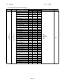
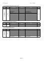
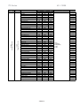
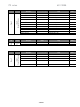
5.1.4 Relay Assignments (Setpoint Page 4)
Security
Level
Level 2
Password Protection
Page 4
Relay Assignments
Setpoint
Page
Description
O/L Trip
I/B Trip
S/C Trip
Overcurrent Trip
Stator RTD Trip
Non-stator RTD Trip
G/F Hi Set Trip
G/F Lo Set Trip
Phase Loss Trip
Accel. Time Trip
Start Curve Trip
Over Frequency Trip
Under Frequency Trip
I*I*T Start Curve
Learned Start Curve
Phase Reversal
Overvoltage Trip
Undervoltage Trip
Power Factor Trip
Tach Accel Trip
Inhibits Trip
Shunt Trip
Bypass Discrepancy
External Input #1
External Input #2
Dual Ramp
Thermostat
O/L Warning
Overcurrent Alarm
Ground Fault Alarm
Under Current Alarm
Motor Running
I/B Alarm
Stator RTD Alarm
Non-Stator RTD Alarm
RTD Failure Alarm
Self Test Fail
Thermal Register
U/V Alarm
O/V Alarm
Power Factor Alarm
KW Demand Alarm
KVA Demand Alarm
KVAR Demand Alarm
Amps Demand Alarm
Timed Output
Run Delay Time
At Speed
1st
Trip Only
Trip
Trip Only
Trip
Trip
Trip
Trip
Trip
Trip
Trip Only
Trip Only
Trip
Trip
Trip
Trip
Trip
Trip
Trip
Trip
Trip
Trip
AUX3
None
None
None
None
Trip
Alarm
Alarm
Alarm
Alarm
None
Alarm
Alarm
Alarm
Alarm
Trip
Alarm
Alarm
Alarm
Alarm
Alarm
Alarm
Alarm
Alarm
None
None
AUX4
Factory Setting
2nd
None
None
None
None
None
None
None
None
None
None
None
None
None
None
None
None
None
None
None
None
None
None
None
None
None
None
None
None
None
None
None
None
None
None
None
None
None
None
None
None
None
None
None
None
None
None
None
None
TOSHIBA- 25
3rd
None
None
None
None
None
None
None
None
None
None
None
None
None
None
None
None
None
None
None
None
None
None
None
None
None
None
None
None
None
None
None
None
None
None
None
None
None
None
None
None
None
None
None
None
None
None
None
None
Range
None
Trip(AUX1)
Alarm(AUX2)
AUX3
AUX4
Section
SP4.1
TX Series
48 - 1250A
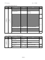
5.1.5 Relay Configuration (Setpoint Page 5)
Security
Level
Level 2
Password Protection
Page 5
Relay Configuration
Setpoint
Page
Description
Factory Setting
Default
Range
Section
Trip (AUX1) Fail-Safe
No
Yes or No
SP5.1
Trip (AUX1) Relay Latched
Yes
Yes or No
SP5.2
Alarm (AUX2) Fail-Safe
No
Yes or No
SP5.1
Alarm (AUX2) Relay Latched
No
Yes or No
SP5.2
AUX3 Relay Fail-Safe
No
Yes or No
SP5.1
AUX3 Relay Latched
No
Yes or No
SP5.2
AUX4 Relay Fail-Safe
No
Yes or No
SP5.1
AUX4 Relay Latched
No
Yes or No
SP5.2
TOSHIBA - 26
TX Series
48 - 1250A
5.1.6 User I/O Configuration (Setpoint Page 6)
Security
Level
Lavel 2
Passowrd Protection
Page 6
User I/O Configuration
Setpoint
Page
Factory Setting
Default
Description
Range
Tachometer Scale Selection
Disabled
Enabled or Disabled
Manual Tach Scale 4.0 mA:
0 RPM
0 - 3600
Manual Tach Scale 20.0 mA:
2000 RPM
0 - 3600
Tach Accel Trip Mode Select
Disabled
Underspeed, Overspeed or Disabled
Tach Ramp Time
20 sec
1 - 120
Tach Underspeed Trip PT
1650 RPM
0-3600
Tach Overspeed Trip PT
1850 RPM
0 - 3600
Tach Accel Trip Delay
1 sec
1 - 60
Analog Output #1
RMS Current
Off, RPM 0-3600, Hottest Non-Stator RTD 0200°C, Hottest Stator RTD
0 - 200°C, RMS Current 0 - 7500 A, % Motor
Load 0 - 600%, kw 0 - 30000kw.
Analog Output #1 4mA:
0
Analog Output #1 20mA:
250
0-65535
Analog Output #2
% Motor Load
Same As Analog Input #1
Analog Output #2 4mA:
0
0-1000%
Analog Output #2 20mA:
1000
0-1000%
Section
SP6.1
SP6.2
SP6.3
0-65535
SP6.4
User Programmable External
Inputs
External Input #1
Disabled
Name Ext. Input #1
Enabled or Disabled
User Defined, up to 15 Characters
External Input #1
NO
Normally Open or Closed
External Input #1
0 sec
0-60 sec
External Input #2
Disabled
Name Ext. Input #2
Enabled or Disabled
User Defined, up to 15 Characters
External Input #2 Type
NO
Normally Open or Closed
External Input #2 Time Delay
0 sec
0-60 sec
Dual Ramp
Dual Ramp
Enabled or Disabled or Dual Ramp
Name Ext. Input #3
Dual Ramp
User Defined, up to 15 Characters
Dual Ramp Type
NO
Normally Open or Closed
Dual Ramp Time Delay
0 sec
0-60 sec
Thermostat
Enabled
Enabled or Disabled
Name Ext. Input #4
Thermostat
User Defined, up to 15 Characters
Thermostat Type
NC
Normally Open or Closed
Thermostat Time Delay
1 sec
0-60 sec
TOSHIBA- 27
SP6.5
TX Series
48 - 1250A
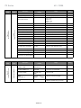
5.1.7 Custom Acceleration Curve (Setpoint Page 7)
Setpoint
Page
Security
Level
Description
Custom Accel Curve
Factory Setting
Default
Range
Disabled
Disabled, Curve A, B, or C
Curve A Voltage Level 1
25%
0-100%
Curve A Ramp Time 1
2 sec
1-60 sec
Curve A Voltage Level 2
30%
0-100%
Curve A Ramp Time 2
2 sec
1-60 sec
Curve A Voltage Level 3
37%
0-100%
Curve A Ramp Time 3
2 sec
1-60 sec
Curve A Voltage Level 4
45%
0-100%
Curve A Ramp Time 4
2 sec
1-60 sec
Curve A Voltage Level 5
55%
0-100%
Curve A Ramp Time 5
2 sec
1-60 sec
Curve A Voltage Level 6
67%
0-100%
Curve A Ramp Time 6
2 sec
1-60 sec
Curve A Voltage Level 7
82%
0-100%
Section
Level 3
Password Protection
Page 7
Custom Acceleration Curve
Custom Curve A
Curve A Ramp Time 7
2 sec
1-60 sec
Curve A Voltage Level 8
100%
0-100%
Curve A Ramp Time 8
2 sec
1-60 sec
Curve A Current Limit
350% FLA
200-600%
SP7.1
Custom Curve B
Same Programmable Data Points and Ranges
as Custom Curve A
Custom Curve C
Same Programmable Data Points and Ranges
as Custom Curve A
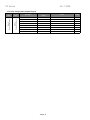
5.1.8 Overload Curve Configuration (Setpoint Page 8)
Setpoint
Page
Security
Level
Description
Factory Setting
Default
Range
Section
Level 3
Password Protection
Page 8
Overload Curve Configuration
Basic Run Overload Curve
Run Curve Locked Rotor Time
O/L Class
1-30 sec, O/L Class
Run Locked Rotor Current
600% FLA
400-800%
Coast Down Timer
Disabled
1-60 Min, Disabled
SP8.1
Basic Start Overload Curve
Start Curve Locked Rotor Time
O/L Class
1-30 sec, O/L Class
Start Locked Rotor Current
600% FLA
400-800%
Acceleration Time Limit
30 sec
1-300 sec, Disabled
Number of Starts Per Hour
Disabled
1-6, Disabled
Time Between Starts Time
Disabled
1-60 Min, Disabled
Area Under Curve Protection
Disabled
Enabled or Disabled
Max I*I*T Start
368 FLA
1-2500 FLA*FLA*sec
Current Over Curve
Disabled
Disabled, Learn, Enabled
Learned Start Curve Bias
10%
5-40%
Time for Sampling
30 sec
1-300 sec
TOSHIBA - 28
SP8.2
SP8.3
SP8.4
TX Series
48 - 1250A
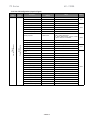
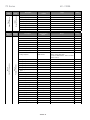
5.1.9 RTD Option Configuration (Setpoint Page 9)
Security
Level
Level 3
Password Protection
Page 9
RTD Configuration
Setpoint
Page
Factory Setting
Default
Description
Range
Section
Use NEMA Temp for RTD Values
Disabled
Enabled or Disabled
# of RTD Used for Stator
4
0-6
SP9.2
RTD Voting
Disabled
Enabled or Disabled
SP9.3
Stator Phase A1 Type
Off
120 OHM NI, 100 OHM NI, 100 OHM PT, 10
OHM CU
RTD #1 Description
Stator A1
User defined, Up to 15 Characters
Stator Phase A1 Alarm Level
Off
0-240C (32-464F), Off
Stator Phase A1 Trip Level
Off
0-240C (32-464F), Off
Stator Phase A2 Type
Off
Same as Stator Phase A1
RTD #2 Description
Stator A2
User defined, Up to 15 Characters
Stator Phase A2 Alarm
Off
0-240C (32-464F), Off
Stator Phase A2 Trip Level
Off
0-240C (32-464F), Off
Stator Phase B1 Type
Off
Same as Stator Phase A1
RTD #3 Description
Stator B1
User defined, Up to 15 Characters
Stator Phase B1 Alarm Level
Off
0-240C (32-464F), Off
Stator Phase B1 Trip Level
Off
0-240C (32-464F), Off
Stator Phase B2 Type
Off
Same as Stator Phase A1
RTD #4 Description
Stator B2
User defined, Up to 15 Characters
Stator Phase B2 Alarm Level
Off
0-240C (32-464F), Off
Stator Phase B2 Trip Level
Off
0-240C (32-464F), Off
Stator Phase C1 Type
Off
Same as Stator Phase A1
RTD #5 Description
Stator C1
User defined, Up to 15 Characters
Stator Phase C1 Alarm Level
Off
0-240C (32-464F), Off
Stator Phase C1 Trip Level
Off
0-240C (32-464F), Off
Stator Phase C2 Type
Off
Same as Stator Phase A1
RTD #6 Description
Stator C2
User defined, Up to 15 Characters
Stator Phase C2 Alarm Level
Off
0-240C (32-464F), Off
Stator Phase C2 Trip Level
Off
0-240C (32-464F), Off
End Bearing Type
Off
Same as Stator A1
RTD #7 Description
End Bearing
User defined, Up to 15 Characters
End Bearing Alarm Level
Off
0-240C (32-464F), Off
End Bearing Trip Level
Off
0-240C (32-464F), Off
Shaft Bearing Type
Off
Same as Stator Phase A1
RTD #8 Description
Shaft Bearing
User defined, Up to 15 Characters
Shaft Bearing Alarm Level
Off
0-240C (32-464F), Off
Shaft Bearing Trip Level
Off
0-240C (32-464F), Off
RTD #9 Type
Off
Same as Stator Phase A1
RTD #9 Description
User defined
User defined, Up to 15 Characters
RTD #9 Alarm Level
Off
0-240C (32-464F), Off
RTD #9 Trip Level
Off
0-240C (32-464F), Off
TOSHIBA- 29
SP9.1
SP9.4
TX Series
48 - 1250A
5.1.9 RTD Option Configuration Page 9 Cont’d
Security
Level
Level 3
Password Protection
Page 9
RTD Configuration
Setpoint
Page
Factory Setting
Default
Description
Range
RTD #10 Type
Off
RTD #10 Description
User defined
User defined, Up to 15 Characters
RTD #10 Alarm Level
Off
0-240C (32-464F), Off
Section
Same as Stator Phase A1
RTD #10 Trip Level
Off
0-240C (32-464F), Off
RTD #11 Type
Off
Same as Stator Phase A1
RTD #11 Description
User defined
User defined, Up to 15 Characters
RTD #11 Alarm Level
Off
0-240C (32-464F), Off
RTD #11 Trip Level
Off
0-240C (32-464F), Off
RTD #12 Type
Off
Same as Stator Phase A1
RTD #12 Description
User defined
User defined, Up to 15 Characters
RTD #12 Alarm Level
Off
0-240C (32-464F), Off
RTD #12 Trip Level
Off
0-240C (32-464F), Off
SP9.4
Setpoint
Page
Security
Level
Page
10
Level
3
5.1.10 Security Set Password Page 10
Factory Setting
Default
Description
Range
Section
Set Level 2 Password
100
000 – 999 Three Digits
SP10.1
Set Level 3 Password
1000
0000 – 9999 Four Digits
SP10.2
5.1.11 Communications Page 11
Security
Level
Level 3
Password Protection
Page 11
Communiications
Setpoint
Page
Factory Setting
Default
Description
Range
Section
Set Front Baud Rate
9.6 KB/sec
2.4, 4.8, 9.6, 19.2, 38.4 KB/sec
SP11.1
Set Modbus Baud Rate
9.6 KB/sec
2.4, 4.8, 9.6, 19.2, 38.4 KB/sec
SP11.2
Modbus Address Number
247
1 – 247
SP11.3
Set Access Code
1
1 – 999
SP11.4
Set Link Baud Rate
38.4 KB/sec
2.4, 4.8, 9.6, 19.2, 38.4 KB/sec
SP11.5
Remote Start/Stop
Disabled
Enabled or Disabled
SP11.6
TOSHIBA - 30
TX Series
48 - 1250A
5.1.12 System (Setpoint Page 12)
Setpoint
Page
Security
Level
Factory Setting
Default
Description
Range
Section
Default Display Screen
Metering Data Page #
1
Enter Metering Page (1-4)
1
Enter Metering Screen
Page 1(1-10)
Page 2 (1-11)
Page 3 (1 - 29)
Page 4 (1 - 6)
RTD Failure Alarm
Disabled
Enabled or Disabled
Thermal Register Alarm
90%
Off, 40-95%
Thermal Alarm Delay
10 sec
1-20 sec
Cold Stall Time
O/L Class
O/L Class (5-30) or 4-40 second time delay
Hot Stall Time
½ O/L Class
½ O/L Class, 4-40 sec
Stopped Cool Down Time
30 Min
10-300 Min
Runing Cool Down Time
15 Min
10-300 Min
Relay Measured Cool Rates
Disabled
Enabled or Disabled
Thermal Register Minimum
15%
10-50%
Motor Design Ambient Temp
40C
10-90C
Motor Design Run Temperature
80% Max
50-100% of Motor Stator Max Temp
Motor Stator Max Temp
INS CLS
INS CLS, 10-240 C
I/B Input to Thermal Register
Enabled
Enabled Only
Use Calculated K or Assign
7
1-50, On
Metering Data Screen #
SP12.1
Level 3
Password Protection
Page 12
System Setpoints
Alarms
SP12.2
Thermal Register Setup Info
SP12.3
Press Enter to Clr Thermal Register
SP12.4
5.1.13 Calibration and Service (Setpoint Page 13)
Security
Level
FACTORY USE ONLY
Page 13
Calibration & Service
Setpoint
Page
Description
Factory Setting
Default
Range
Section
Set Date and Time
(DDMMYY:HHMM)
FACTORY SET;
##/##/## ##:##
Enter Date (DDMMYYYY)
FACTORY SET;
##/##/####
D=1-31, M=1-12, Y=1970-2069
Enter Time (HH:MM)
FACTORY SET;
##:##
H=00-23, M=0-59
Model #
Firmware REV. #
FACTORY SET;
######
######
Display Only, Cannot be changed
SP13.2
Available to Qualified Factory Personnel
SP13.3
Press Enter to Access Factory
Settings
TOSHIBA- 31
SP13.1
TX Series
48 - 1250A
5.2 Setpoint Menu
MENU
(1)
Note:
1. Push MENU key to toggle the screens between Setpoint Menu and Metering
Menu.
2. Follow the arrow keys to get to different screens.
Example: For Page 3 PHASE & GROUND SETTINGS, press the MENU key and
the DOWN ARROW two times.
PAGE 1 BASIC
CONFIGURATION
LEVEL 1
PAGE 2 STARTER
CONFIGURATION
PAGE 3
PHASE &
GROUND SETTINGS
PAGE 4 RELAY
ASSIGNMENT
LEVEL 2
PAGE 5 RELAY
CONFIGURATION
PAGE 6
USER I/O
CONFIGURATION
PAGE 7
CUSTOM
ACCELERATION CURVE
PAGE 8 OVERLOAD
CURVE CONFIGURATION
PAGE 9 RTD
CONFIGURATION
LEVEL 3
PAGE 10 SECURITY
SET PASSWORD
PAGE 11
COMMUNICATIONS
PAGE 12
SYSTEM
SETPOINTS
FACTORY
LEVEL
PAGE 13 CALIBRATION
& SERVICE
TOSHIBA - 32
TX Series
48 - 1250A
SP.1 Basic Configuration (Setpoint Page 1)
In Setpoint Page 1, the TX is looking for the following basic
nameplate data of the motor.
SP1.1 Motor Full Load Amps: Allows the user to enter the
motor’s FLA rating. Range of adjustment is 50 - 100%
(less programmed service factor).
MENU
PAGE 1 BASIC
CONFIGURATION
MOTOR FULL LOAD AMPS
: 200 AMPS
Range: 50 - 100% of Unit
MAX CURRENT AMPS
Increments of 1
SP1.2 Service Factor: Sets the pickup point on the overload
curve as defined by the programmed motor full load
current. Ex: If the motor FLA is 100 and the service
factor is 1.15, the TX overload pickup point will be 115
Amps.
SERVICE FACTOR
: 1.15 X FLA
Range: 1.00 - 1.3
Increments of 0.01
SP1.3 Overload Class: Choose the motor protection overload
class, range from 5-30.
Ex: Overload Class 10 will trip in 10 seconds at six
times FLA.
Range: 5 - 30
Increments of 5
OVERLOAD
CLASS: 10
NEMA
DESIGN: B
Range: A - F
INSULATION
CLASS: B
Range: A - S
LINE VOLTAGE
INPUT: 480 VOLTS
Range: 208 - 600
LINE FREQUENCY
HZ: 60
Range: 50 or 60
SP1.4
NEMA design: The motor design maximum allowed slip (Select from
Class A through F).
SP1.5
Insulation Class: The motor insulation temperature class (Select A,
B, C, E, F, H, K, N or S).
SP1.6
Line Voltage Inut: Applied system nominal voltage.
SP1.7
Line Frequency: The user may choose either 50 Hz or 60 Hz.
TOSHIBA- 33
TX Series
48 - 1250A
SP.2 Starter Configuration (Setpoint Page 2)
MENU
(Hit DOWN ARROW one time)
PAGE 2 STARTER
CONFIGURATION
START CONTROL MODE
: START RAMP 1
JOG, START RAMP 1,
START RAMP 2, DUAL
RAMP, CUSTOM ACCEL
CURVE,START DISABLED
If
VOLTAGE
selected
these
screens
will appear.
If
CURRENT
selected
these
screens
will appear.
JOG VOLTAGE
: OFF
INITIAL VOLTAGE
#1: 20%
Range: 5 - 75% or Off
Increments 5
START RAMP #1 TYPE
: VOLTAGE
Options:Voltage, Current
or Off
Range: 0 - 100%
Increments of 1
Range: 0 - 300%
Increments of 1
RAMP TIME
#1: 10 SEC.
Range: 0 - 120 SEC.
Increments of 1
RAMP TIME
#1: 10 SEC.
Range: 0 - 120 SEC
Increments of 1
CURRENT LIMIT
#1: 350% FLA
Range: 200 - 600%
Increments of 10
START RAMP #2 TYPE
: OFF
Options: Voltage, Current
or Off
KICK START
TYPE: OFF
Range: Voltage or Off
DECELERATION
: DISABLED
Range: Enabled or Disabled
TIMED OUTPUT
TIME: OFF
Range: 1 - 1000 sec, OFF
Increments of 1
INITIAL CURRENT
#1: 200% FLA
If
VOLTAGE
selected
INITIAL VOLTAGE
these
#2: 60%
screens
will appear. Range: 0 - 100%
MAXIMUM CURRENT
#1: 350% FLA
Range: 200-600%
Increments of 10
If
CURRENT
selected
INITIAL CURRENT
these
#2: 200% FLA
screens
will appear. Range: 0 - 300%
Increments of 1
Increments of 1
RAMP TIME
#2: 10 SEC.
Range: 0 - 120 SEC.
Increments of 1
RAMP TIME
#2: 10 SEC.
Range: 0 - 120 SEC
Increments of 1
CURRENT LIMIT
#2: 350% FLA
Range: 200 - 600%
Increments of 10
MAXIMUM CURRENT
#2: 350% FLA
Range: 200-600%
Increments of 10
KICK START VOLTAGE
: 65%
Range: 10 - 100%
Increments of 5
KICK START TIME
: 0.50 SEC.
Range: 0.10 - 2.00
Increments of 0.10
START DECELERATION
VOLTAGE: 60%
Range: 0 - 100%
Increments of 1
RUN DELAY
TIME: 1 SEC.
Range: 0 - 30 sec, OFF
Increments of 1
STOP DECELERATION
VOLTAGE: 30%
Range: 0 - 59%
Increments of 1
AT SPEED DELAY
TIME: 1 SEC.
Range: 0 - 30 sec, OFF
Increments of 1
DECELERATION
TIME: 5 SEC.
Range: 1 - 60
Increments of 1
BYPASS PULL-IN
CURRENT: 100% FLA
Range: 90 - 300%
Increments of 1
TOSHIBA - 34
TX Series
48 - 1250A
SP.2 Starter Configuration (Setpoint Page 2)
Provides multiple choices for starting ramps that can be
selected for particular loads and applications.
SP2.1 Start Control Mode: Dual Ramp, Custom
Accel Curve, Tach Ramp, Jog Voltage, Start
Ramp 1, Start Ramp 2.
• Dual Ramp: The dual ramp mode works in
conjunction with External Input #3. This allows
the user to switch between the two start ramps
without having to reconfigure the start mode.
(For details on configuring External Input #3 for
DUAL RAMP see Setpoint Page 6.)
• Custom Accel Curve: Allows the user to
custom design the acceleration start curve to
the application. (See setpoint page 7 for
configuration setup.) Note: If Custom Accel
Curve has not been enabled in setpoint page 7,
the TX will ignore the start control mode and
read this setpoint as disabled.
• Tach Ramp: See setpoint page 6 for
configuration setup of tachometer input.
(Pending)
SP2.2 Jog Voltage: The voltage level necessary to
cause the motor to slowly rotate.
SP2.3 Start Ramp 1 Type: The ramp type can be
setup for either Voltage or Current. If Voltage is
selected, initial voltage, ramp time and current
limit are adjustable. If Current is selected, initial
current, ramp time and maximum current are
adjustable.
Start Ramp 1 Type: Voltage
• Voltage Ramping is the
most reliable starting
method, because the
starter will eventually
reach an output voltage
high enough to draw full
current and develop full
torque. This method is
useful for applications
where the load
conditions change
frequently and where
different levels of torque
are required. Typical applications include
material handling conveyors, positive
displacement pumps and drum mixers.
Voltage is increased from a starting point (Initial
Torque) to full voltage over an adjustable period
of time (Ramp Time). To achieve Voltage
Ramping, select VOLTAGE for the START RAMP
#1 TYPE setpoint and set CURRENT LIMIT #1
setpoint to 600% (the maximum setting). Since
TOSHIBA- 35
this is essentially Locked Rotor Current on most
motors, there is little or no Current Limit effect on
the Ramp profile.
• Voltage Ramping with Current Limit is the most
used curve and is similar to voltage ramping.
However, it adds an adjustable maximum current
output. Voltage is increased gradually until the
setting of the Maximum Current Limit setpoint is
reached. The voltage is held at this level until
the motor accelerates to full speed. This may
be necessary in applications where the
electrical power is limited. Typical applications
include portable or emergency generator
supplies, utility power near the end of a
transmission line and utility starting power
demand restrictions. Note: Using Current Limit
will override the Ramp Time setting if necessary,
so use this feature when acceleration time is
not critical. To achieve Voltage Ramping with
Current Limit, select VOLTAGE for the START
RAMP #1 setpoint and set CURRENT LIMIT #1
setpoint to a desired lower setting, as
determined by your application requirements.
Start Ramp 1 Type: Current
Current Ramping (Closed Loop Torque
Ramping) is used for smooth linear acceleration
of output torque. Output voltage is constantly
updated to provide the linear current ramp, and
therefore the available torque is maximized at
any given speed. This is for applications where
rapid changes in torque may result in load
damage or equipment changes. Typical
applications include overland conveyors if belt
stretching occurs; fans and mixers if blade
warping is a problem; and material handling
systems if stacked products fall over or break.
This feature can be used with or without the
Maximum Current Limit setting. To achieve
Current Ramping select CURRENT for START
RAMP #1 TYPE setpoint and the MAXIMUM
CURRENT #1 setpoint to the desired level.
Current Limit Only: (Current Step) start uses
the Current Limit feature exclusively. This
method of starting eliminates the soft start
voltage/current ramp and instead, maximizes
the effective application of motor torque within
the limits of the motor. In this mode, setpoint
RAMP TIME #1 is set to zero (0), so the output
current jumps to the current limit setting
immediately. Typically used in with a limited
power supply, when starting a difficult load such
as a centrifuge or deep well pump, when the
motor capacity is barely adequate (stall
condition or overloading occurs) or if other
starting modes fail. Since ramp times are set to
zero (0). START RAMP #1 TYPE is set to
TX Series
48 - 1250A
either VOLTAGE or CURRENT.
• Initial Torque (Initial Voltage #1 or Initial
Current #1): Sets the initial start point of either
the Voltage Ramp or the Current Ramp. Every
load requires some amount of torque to start from
a standstill. It is inefficient to begin ramping the
motor from zero every time, since between zero
and the WK2 break-away torque level, no work is
being performed. The initial torque level should
be set to provide enough torque to start rotating
the motor shaft, enabling a soft start and
preventing torque shock damage. Setting this
start point too high will not damage the starter,
but may reduce or eliminate the soft start effect.
• Ramp Time #1: Sets the maximum allowable
time for ramping the initial voltage or current
(torque) setting to either of the following:
1) the Current Limit setting when the motor is still
accelerating, or
2) full output voltage if the Current Limit is set to
maximum.
Increasing the ramp time softens the start
process by gradually increasing the voltage or
current. Ideally, the ramp time should be set for
the longest amount of time the application will
allow (without stalling the motor). Some
applications require a short ramp time due to the
mechanics of the system. (i.e., centrifugal
pumps, because pump problems can occur due
to insufficient torque).
• Current Limit: Sets the maximum motor
current the starter will allow during Ramping. As
the motor begins to ramp, the Current Limit
feature sets a ceiling at which the current draw
is held. Current Limit remains in effect until the
following occurs:
1) the motor reaches full speed (detected by the
At-Speed detection circuit) or
2) the Overload Protection trips on Motor Thermal
Overload.
Once the motor reaches full speed, the Current
Limit feature becomes inactive.
In the Voltage Ramp Profile, the voltage output is
increased until it reaches the Current Limit. Ramp
time is the maximum amount of time it takes for
the voltage to increase until the Current Limit
setting takes over. With some load conditions,
the Current Limit is reached before the Ramp
Time expires.
SP2.4 Start Ramp 2: The same options and screen
setups as Start Ramp 1. Note: CUSTOM
ACCEL CURVE overrides the voltage or current
start in Ramps 1 and 2 when selected to be the
start control mode.
SP2.5 Kick Start: Used as an initial energy burst in
applications with high friction loads.
• Kick Start Voltage: The initial voltage (as a
percent of full voltage value) that is needed to
start the motor (i.e. Breakaway or Initial Torque).
• Kick Start Time: The time the initial torque
boost is applied.
SP2.6
Deceleration: Allows the motor to gradually
come to a soft stop.
• Start Deceleration Voltage: The first part of
the deceleration ramp. The TX initially drops to
this voltage level upon receiving a STOP
command. (Represented as a percent of
voltage value.)
• Stop Deceleration Voltage: The drop-off point
of the deceleration ramp. (Percent of voltage
value.)
• Deceleration Time: Decel ramp time.
SP2.7
Timed Output: Used with an AUX relay. When
enabled, and upon a start command, it energizes
the assigned relay for the programmed time. At
the end of the programmed time the relay deenergizes. See Setpoint Page 4.
SP2.8
Run Delay Time: Used with an AUX3 relay.
When enabled, and upon a start command, it
waits until the programmed time has expired.
The relay energizes and remains so until a stop
command is received. It de-energizes upon
receiving a stop command. See Setpoint Page
4.
SP2.9
At Speed Delay Time: Used with an AUX4 relay,
it waits until after the motor reaches the end of
ramp and the programmed delay time has
expired. The relay energizes until a stop
command has been received. See Setpoint Page
4.
The Current Ramp profile varies the output
voltage to provide a linear increase in current up
to the Maximum Current setpoint value. A closed
loop feedback of motor current maintains the
Current Ramp profile.
TOSHIBA - 36
TX Series
48 - 1250A
MENU
(Hit DOWN ARROW two times)
PAGE 3 PHASE &
GROUND SETTINGS
SP.3 Phase & Ground Settings (Setpoint Page 3)
(Security Level: 2)
Note:
Proper phase sequence must be observed when
connecting the input power. For example, phase A
must lead phase B, which in turn must lead phase
C by 120° respectively. If the phase rotation is not
correct, a fault light and the LCD display will
indicate the problem.
SP3.1 Imbalance Alarm Level: This is an advance
warning of a phase imbalance problem. The
problem may not be a fault in the motor, but merely
caused by imbalanced voltages.
• Imbalance Alarm Delay: The amount of time the
imbalance condition must exist before an alarm
occurs.
SP3.2 Imbalance Trip Level: This will trip the motor on
excessive phase imbalance. The trip level should
be programmed to a higher value than the alarm
level.
• Imbalance Trip Delay: The amount of time the
imbalance condition must exist before a trip will
occur.
SP3.3 Undercurrent Alarm Level: Typically used to
warn of possible load loss, a coupling breaking or
other mechanical problems.
• Undercurrent Alarm Delay: The amount of time
the undercurrent condition must exist before an
alarm will occur.
SP3.4 Overcurrent Alarm Level: Typically used to
indicate when the motor is overloaded. This feature
can be used to either stop the feed to the
equipment or warn operators of an overload
condition.
• Overcurrent Alarm Delay: The amount of time
the overcurrent condition must exist before an
alarm will occur.
TOSHIBA- 37
IMBALANCE ALARM
LEVEL: 15% FLA
IMBALANCE ALARM
DELAY:
1.5 SEC.
Range: 5 - 30%, OFF
Increments of 1
Range: 1.0 - 20.0 SEC.
Increments of 0.1
IMBALANCE TRIP
LEVEL: 20%FLA
Range: 5 - 30%, OFF
Increments of 1
IMBALANCE TRIP
DELAY: 2.0 SEC.
Range: 1.0 - 20.0 SEC.
Increments of 0.1
UNDERCURRENT ALARM
LEVEL:
OFF
Range: 10 - 90%, OFF
Increments of 1
UNDERCURRENT ALARM
DELAY: 2.0 SEC.
Range: 1.0 - 60.0 SEC.
Increments of 0.1
OVERCURRENT ALARM
LEVEL: OFF
Range: 100 - 300%, OFF
Increments of 1
OVERCURRENT ALARM
DELAY: 2.0 SEC.
Range: 1.0 - 20.0 SEC., OFF
Increments of 0.1
OVERCURRENT TRIP
LEVEL: OFF
Range: 100 - 300%, OFF
Increments of 1
OVERCURRENT TRIP
DELAY: 2.0 SEC.
Range: 1.0 - 20.0 SEC.
Increments of 0.1
PHASE LOSS TRIP
: DISABLED
Options: Enabled or Disabled
PHASE LOSS TRIP
DELAY:
0.1 SEC.
Range: 0 - 20.0 SEC.
Increments of 0.1
PHASE ROTATION
DETECTION: DISABLED
Options: Enabled or Disabled
PHASE ROTATION
: ABC
Options: ABC, ACB
GROUND FAULT ALARM
LEVEL: OFF
Range: 5 - 90%, OFF
Increments of 1
GROUND FAULT ALARM
DELAY: 0.1 SEC.
Range: 0.5 - 20.0 SEC.
Increments of 0.1
GROUND FAULT LOSET
TRIP LEVEL: OFF
Range: 5 - 90%, OFF
Increments of 1
GROUND FAULT LOSET
TRIP DELAY: 0.5 SEC
Range: 1.0 - 20.0 SEC., OFF
Increments of 0.1
GROUND FAULT HISET
TRIP LEVEL: OFF
Range: 5 - 90%, OFF
Increments of 1
GROUND FAULT HISET
TRIP DELAY: 0.008 SEC.
Range: 0.008 - 0.250 SEC.
Increments of 0.002
OVERVOLTAGE ALARM
LEVEL: OFF
Range: 5 - 30%, OFF
Increments of 1
OVERVOLTAGE ALARM
DELAY: 1.0 SEC.
Range: 1.0 - 30.0 SEC.
Increments of 0.1
OVERVOLTAGE TRIP
LEVEL: OFF
Range: 5 - 30%, OFF
Increments of 1
OVERVOLTAGE TRIP
DELAY: 2.0 SEC.
Range: 1.0 - 30.0 SEC.
Increments of 0.1
UNDERVOLTAGE ALARM
LEVEL: OFF
Range: 5 - 30%, OFF
Increments of 1
UNDERVOLTAGE ALARM
DELAY: 1.0 SEC.
Range: 1.0 - 30.0 SEC.
Increments of 0.1
UNDERVOLTAGE TRIP
LEVEL: OFF
Range: 5 - 30%, OFF
Increments of 1
UNDERVOLTAGE TRIP
DELAY: 2.0 SEC.
Range: 1.0 - 30.0 SEC.
Increments of 0.1
LINE FREQUENCY TRIP
WINDOW: DISABLED
Range: 0 - 6, Disabled
Increments of 1
LINE FREQUENCY TRIP
DELAY: 1.0 SEC.
Range: 1.0 - 20.0 SEC.
Increments of 0.1
TX Series
48 - 1250A
SP.3 Phase & Ground Settings (Setpoint Page 3)
continued
MENU
(Hit DOWN ARROW two times)
PAGE 3 PHASE &
GROUND SETTINGS
SP.3 Phase & Ground Settings (Setpoint Page 3)
(Security Level: 2)
SP3.5 Overcurrent Trip Level: Typically used to
indicate the motor is severely overloaded and at
which point a trip
occurs.
• Overcurrent Trip
Delay: The
amount of time
the overcurrent condition must exist before a trip
will occur.
SP3.6 Phase Loss Trip: When enabled, the TX will trip
the motor off-line upon a loss of phase power.
• Phase Loss Trip Delay: The amount of time the
phase loss condition must exist before a trip will
occur.
SP3.7 Phase Rotation Detection: The TX is
continuously monitoring the phase rotation. Upon
a start command, a trip will occur if it detects a
change in the phase rotation.
• Phase Rotation: There are two possible phase
rotation options: ABC or ACB. This setpoint
monitors the wiring to ensure that the phase
rotation is correct. To view the present phase
rotation, go to Metering Page1, screen number 4.
POWER FACTOR LEAD
P/F ALARM: OFF
P/F LEAD ALARM
DELAY:
1 SEC.
Range: .01 - 1.00, OFF
Increments of .01
Range: 1 - 120 SEC
Increments of 1
POWER FACTOR LEAD
P/F TRIP: OFF
Range: .01 - 1.00, OFF
Increments of .01
P/F LEAD TRIP
DELAY: 1.0 SEC.
Range: 1 - 120 SEC.
Increments of 1
POWER FACTOR LAG
P/F ALARM:
OFF
Range: .01 - 1.00, OFF
Increments of .01
P/F LAG ALARM
DELAY: 1.0 SEC.
Range: 1 - 120 SEC.
Increments of 1
POWER FACTOR LAG
P/F TRIP:
OFF
Range: .01 - 1.00, OFF
Increments of .01
P/F LAG TRIP
DELAY: 1.0 SEC.
Range: 1 - 120 SEC.
Increments of 1
POWER DEMAND
PERIOD: 10 MINUTES
Range: 1 - 60 Minutes
Increments of 1
KW DEMAND ALARM
PICKUP: OFF KW
Range: OFF, 1 - 100000
Increments of 1
KVA DEMAND ALARM
PICKUP: OFF KVA
Range: OFF, 1 - 100000
Increments of 1
KVAR DEMAND ALARM
PICKUP: OFF KVAR
Range: OFF, 1 - 100000
Increments of 1
AMPS DEMAND ALARM
PICKUP: OFF AMPS
Range: OFF, 1 - 100000
Increments of 1
SP3.10 Ground Fault Hiset Trip Level: Used to trip
the motor (within milliseconds) upon detecting a
SP3.8 Ground Fault Alarm: Typically used to warn of
high level of ground current leakage. This
low level ground current leakage
setpoint is intended to detect low impedance
faults. (Pending)
• Ground Fault Alarm Delay: The amount of time
that the ground fault condition must exist before an
• Ground Fault Hiset Trip Delay: The amount of
alarm will occur.
time that the ground fault condition must exist
before a trip will occur.
SP3.9 Ground Fault Loset Trip Level: Typically used
to trip the motor on a low level of ground current
leakage. This setpoint is intended to detect high SP3.11 Overvoltage Alarm Level: Typically used to
indicate when the line voltage is too high. This is
impedance faults. (Pending)
an alarm level.
• Ground Fault Loset Trip Delay: The amount of
time that the ground fault condition must exist
before a trip will occur.
TOSHIBA - 38
• Overvoltage Alarm Delay: The amount of time
that the overvoltage condition must exist before a
trip will occur.
TX Series
48 - 1250A
SP3.12 Overvoltage Trip Level: Typically used to
indicate that the line voltage is too high and at
which point a trip occurs
SP3.19 Power Factor Lag Trip: The acceptable
amount of power factor lag before a trip is
generated.
• Power Factor Lag Delay: The amount of time
that the power factor lag condition must exist
beyond the window before a trip will occur.
• Overvoltage Trip Delay: The amount of time
that the overvoltage condition must exist before a
trip will occur.
SP3.13 Undervoltage Alarm Level: Typically used to
indicate when the line voltage is too low. This is
an alarm level.
• Undervoltage Alarm Delay: The amount of
time that the overvoltage condition must exist
before a trip will occur.
SP3.14 Undervoltage Trip Level: Typically used to
indicate that the line voltage is too low and at
which point a trip occurs
SP3.20 Power Demand Period: The TX Series
measures the damand of the motor for several
parameters (current, kW, kvar, kVA). The
demand values of motors assists in energy
management programs where processes may
be altered or scheduled to reduce overall
demand. Demand is calculated by a
programmed amount of time where current, kW,
kvar and kva samples are taken and then
averaged and stored to assess demand.
• Undervoltage Trip Delay: The amount of time
that the undervoltage condition must exist before
a trip will occur.
SP3.15 Line Frequency Trip Window: The acceptable
amount of drift above or below the line frequency
before a trip is generated.
• Line Frequency Trip Delay: The amount of
time that the frequency drift condition must exist
beyond the window before a trip will occur.
SP3.16 Power Factor Lead Alarm: Typically used to
indicate a leading power factor.
• Power Factor Lead Alarm Delay: The amount
of time that the power factor lead condition must
exist beyond the window before a trip will occur.
SP3.17 Power Factor Lead Trip: The acceptable
amount of power factor lead before a trip is
generated.
• Power Factor Lead Delay: The amount of time
that the power factor lead condition must exist
beyond the window before a trip will occur.
SP3.18 Power Factor Lag Alarm: Typically used to
indicate a lagging power factor.
• Power Factor Lag Alarm Delay: The amount of
time that the power factor lagging condition must
exist beyond the window before a trip will occur.
TOSHIBA- 39
TX Series
48 - 1250A
SP.4 Relay Assignment (Setpoint Page 4)
MENU
PHASE REVERSAL
1ST: TRIP
I/B ALARM
1ST: ALARM
OVERVOLTAGE TRIP
1ST: TRIP
STATOR RTD ALARM
1ST: ALARM
UNDERVOLTAGE TRIP
1ST: TRIP
NON-STATOR RTD ALARM
1ST: ALARM
POWER FACTOR TRIP
1ST: TRIP
RTD FAILURE ALARM
1ST: ALARM
(Hit DOWN ARROW three times)
PAGE 4 RELAY
ASSIGNMENT
O/L TRIP
1ST: TRIP ONLY
Range: TRIP (AUX1),
ALARM (AUX2), AUX3,
AUX4
I/B TRIP
1ST: TRIP
S/C TRIP
1ST: TRIP ONLY
TACH ACCEL TRIP
1ST: TRIP
OVERCURRENT TRIP
1ST: TRIP
INHIBITS TRIP
1ST: TRIP
STATOR RTD TRIP
1ST: TRIP
SHUNT TRIP
1ST: AUX 3
NON-STATOR RTD TRIP
1ST: TRIP
SELF-TEST FAIL
1ST: TRIP
THERMAL REGISTER
1ST: ALARM
U/V ALARM
1ST: ALARM
BYPASS DISCREPANCY
1ST: NONE
G/F HI SET TRIP
1ST: TRIP
G/F LO SET TRIP
1ST: TRIP
PHASE LOSS TRIP
1ST: TRIP
ACCEL. TIME TRIP
1ST: TRIP ONLY
START CURVE TRIP
1ST: TRIP ONLY
OVER FREQUENCY TRIP
1ST: TRIP
O/V ALARM
1ST: ALARM
EXTERNAL INPUT #1
1ST: NONE
POWER FACTOR ALARM
1ST: ALARM
EXTERNAL INPUT #2
1ST: NONE
KW DEMAND ALARM
1ST: ALARM
DUAL RAMP
1ST: NONE
KVA DEMAND ALARM
1ST: ALARM
THERMOSTAT
1ST: TRIP
O/L WARNING
1ST: ALARM
OVERCURRENT ALARM
1ST: ALARM
UNDER FREQUENCY TRIP
1ST: TRIP
GROUND FAULT ALARM
1ST: ALARM
I*I*T START CURVE
1ST: TRIP
UNDERCURRENT ALARM
1ST: ALARM
LEARNED START CURVE
1ST: TRIP
MOTOR RUNNING
1ST: NONE
TOSHIBA - 40
KVAR DEMAND ALARM
1ST: ALARM
AMPS DEMAND ALARM
1ST: ALARM
TIMED OUTPUT
1ST: NONE
RUN DELAY TIME
1ST: NONE
AT SPEED
1ST: AUX4
TX Series
48 - 1250A
SP.4 Relay Assignment (Setpoint Page 4)
(Security Level: 2)
All of the protection functions of the TX are user programmable to an
output relay. The factory will ship with all tripping functions assigned to
TRIP (AUX1) relay, and all alarm functions to ALARM (AUX2) relay. Note:
AUX1 - 4 are Factory Set and should not be changed.
SP4.1
The following is a list of all the user programmable functions.
Note: The Relay Assignments are factory defaults.
FUNCTIONS
IMBALANCE TRIP
SHORT CIRCUIT TRIP
OVERCURRENT TRIP
STATOR RTD TRIP
NON-STATOR RTD TRIP
GROUND FAULT HI SET TRIP
GROUND FAULT LO SET TRIP
PHASE LOSS TRIP
ACCELERATION TIME
START CURVE TRIP
OVER FREQUENCY TRIP
UNDER FREQUENCY TRIP
I*I*T START CURVE
LEARNED START CURVE
PHASE REVERSAL
OVERVOLTAGE TRIP
UNDERVOLTAGE TRIP
POWER FACTOR TRIP
TACH ACCEL TRIP
INHIBITS TRIP
SHUNT TRIP
BYPASS DISCREPANCY
EXTERNAL INPUT 1
EXTERNAL INPUT 2
DUAL RAMP
THERMOSTAT
OVERLOAD WARNING
OVERCURRENT ALARM
GROUND FAULT ALARM
UNDERCURRENT ALARM
MOTOR RUNNING
IMBALANCE ALARM
STATOR RTD ALARM
NON-STATOR RTD ALARM
RTD FAILURE ALARM
SELF TEST FAIL
THERMAL REGISTER
U/V ALARM
O/V ALARM
POWER FACTOR ALARM
KW DEMAND ALARM
KVA DEMAND ALARM
KVAR DEMAND ALARM
AMPS DEMAND ALARM
TIMED OUTPUT
RUN DELAY TIME
AT SPEED
RELAY ASSIGNMENT
TRIP (AUX1)
TRIP (AUX1)
TRIP (AUX1)
TRIP (AUX1)
TRIP (AUX1)
TRIP (AUX1)
TRIP (AUX1)
TRIP (AUX1)
TRIP (AUX1)
TRIP (AUX1)
TRIP (AUX1)
TRIP (AUX1)
TRIP (AUX1)
TRIP (AUX1)
TRIP
TRIP
TRIP
TRIP
TRIP
TRIP
AUX 3
NONE
NONE
NONE
NONE
TRIP (AUX 1)
ALARM (AUX2)
ALARM (AUX2)
ALARM (AUX2)
ALARM (AUX2)
NONE
ALARM (AUX2)
ALARM (AUX2)
ALARM (AUX2)
ALARM (AUX2)
TRIP (AUX1)
ALARM (AUX2)
ALARM
ALARM
ALARM
ALARM
ALARM
ALARM
ALARM
NONE
NONE
AUX4
TOSHIBA- 41
TX Series
48 - 1250A
SP.5 Relay Configuration (Setpoint Page 5)
(Security Level: 2)
In Setpoint Page 5 the user
can configure the four output
relays as either fail-safe or
non fail-safe and latching or
non-latching.
MENU
(Hit DOWN ARROW four times)
PAGE 5 RELAY
CONFIGURATION
TRIP (AUX1) RELAY
FAIL-SAFE:
NO
TRIP (AUX1) RELAY
LATCHED:
YES
Options: Yes or No
SP5.1 When a relay has been configured as fail-safe
and power is applied, the relay will be
energized. The relay will then de-energize
when an event occurs or if the power fails.
NOTE: The relays in the TX will not prevent a
start sequence unless they are wired in as
interlocks. If power is lost, the motor power
is also lost.
SP5.2 A relay configured as non-latching will reset
itself when the cause of the trip event is not
continuous. The TRIP (AUX1) relay should
always be programmed for latching, because
this trip should require a visual inspection of
the motor and starter before issuing a
manual reset to release the relay after a trip
has been stored.
ALARM (AUX2) RELAY
FAIL-SAFE:
NO
ALARM (AUX2) RELAY
LATCHED: NO
AUX 3 RELAY
FAIL-SAFE: NO
AUX3 RELAY
LATCHED:
NO
AUX4 RELAY
FAIL-SAFE: NO
AUX4 RELAY
LATCHED: NO
TOSHIBA - 42
TX Series
48 - 1250A
SP.6 User I/O Configuration (Setpoint Page 6)
(Security Level: 2)
ENABLED
PAGE 6 USER I/O
CONFIGURATION
TACHOMETER SCALE
SELECTION: DISABLED
Options: ENABLED or
DISABLED
MANUAL TACH SCALE
4.0 mA: 0 RPM
Range: 0-3600
Increments of 5
MANUAL TACH SCALE
20.0 mA: 2000 RPM
TACH ACCEL TRIP MODE
SELECT: DISABLED
Range: 0-3600
Increments of 5
TACH RAMP TIME
: 20 SEC
Range: 1 - 120 SEC.,
Disabled
Increments of 1
TACH UNDERSPEED TRIP
PT: 1650 RPM
Range: 0 - 3600
Increments of 5
TACH OVERSPEED TRIP
PT: 1850 RPM
Range: 0 - 3600
Increments of 5
Options: UNDERSPEED,
OVERSPEED or DISABLED
ANALOG OUTPUT #1
:RMS CURRENT
Range:
Range
Analog Output
RPM
0 - 3600
Hottest Bearing
0 - 200°C
Hottest Stator RTD 0 - 200°C
RMS Current
0 - 6500A
% Motor Load
0 - 1000%
KW
0-30000 KW
OFF
Increments of 1
ANALOG OUTPUT #2
:% MOTOR LOAD
Range: See Analog Output #1
Increments of 1
TACH ACCEL TRIP
DELAY: 1 SEC
Range: 1 - 60
Increments of 1
ANALOG OUTPUT #1
4ma: 0
Range: 0-65535
Increments of 1
ANALOG OUTPUT #2
4mA: 0
Range: 0-1000%
Increments of 1
USER PROGRAMMABLE
EXTERNAL INPUTS
Continued...
TOSHIBA- 43
ANALOG OUTPUT #1
20mA: 250
Range: 0-65535
Increments of 1
ANALOG OUTPUT #2
20mA: 1000
Range: 0-1000%
Increments of 1
TX Series
48 - 1250A
SP.6 User I/O Configuration (Setpoint Page 6)
(Security Level: 2)
The TX can be configured to accept a tachometer
feedback signal through the 4-20mA input and has two
options available for scaling the tachometer input. Note:
At the time of this printing, SP6.1 - SP6.4 are pending.
SP6.1
The first screen of setpoint page 6 is
TACHOMETER SCALE SELECTION. When
this is set to AUTO, the display prompts the
user to program the TX to sense when the
motor speed is zero. It will prompt again when
the motor speed is at maximum RPM. Once
these inputs are given, the TX automatically
scales the range of the tachometer feedback to
give a linear RPM ramp. When this is set to
MANUAL, the user will need to input the
tachometer scale of the 4-20mA input range.
SP6.5 The TX provides two 4-20mA analog outputs.
Each analog output is independent of the other
and can be assigned to monitor different
functions. The available output ranges are
RPM, Hottest Non-Stator (Bearing) RTD,
Hottest Stator RTD, RMS current, or % Motor
Load.
• Analog Output #1 – Select a function from the
available five options to be transmitted from the
4-20mA output. Note: If selecting RPM, the
Tachometer feedback input signal must be
present in order for the TX to give proper
output. If selecting RTD, the RTD option must
be installed and an RTD input signal must be
present for a proper output to be given from the
analog output.
• Analog Output #1 4 mA: Enter a value that the
4mA level will represent for the selected
function; typically this value should be 0.
• Analog Output #1 20 mA: Enter a value that the
20mA level will represent for the selected
function.
• Press Enter if Motor Speed = 0 RPM: This
setpoint will be displayed when the user has
selected Auto Scaling Mode. The TX is
prompting the user to program when the motor
speed is at zero. This will be the lowest value
on the scale.
• Press Enter if Motor Speed = MAX RPM: The
TX is now prompting the user to program the
unit when the motor is at maximum speed. This
will be the highest value on the scale.
SP6.6
• Press Enter to Scale: This is a prompt to the
user that the unit has recorded the values of the
tachometer input based on input from the user
and is now ready to automatically scale the range
of the tachometer input.
• Manual Tach Scale 4.0 mA: The unit is looking
for an RPM value to assign to the lowest point on
the scale. This value should represent the
motor at zero speed.
• Manual Tach Scale 20.0 mA: The unit is looking
for an RPM value to assign to the highest point
on the scale. This value should represent the
motor at full speed.
SP6.2
Feedback Ramp Time: This is the duration of
the tachometer ramp time.
SP6.3
Tach Accel Trip: The maximum allowed
percentage of slip per NEMA design of the motor.
SP6.4
Tach Accel Trip Delay: The duration of time that
the Tach Accel trip condition must persist before
a trip is generated.
TOSHIBA - 44
Analog Output #2 – All of the setpoints and
setup screens for Analog Output #2 are the
same as those for Analog Output #1.
TX Series
48 - 1250A
SP.6 User I/O Configuration (Setpoint Page 6)
(Security Level: 2)
USER
PROGRAMMABLE
EXTERNAL
INPUTS
(Continued)
EXTERNAL INPUT #1
SELECT: DISABLED
Options: Enabled or Disabled
EXTERNAL INPUT #2
SELECT: DISABLED
Options: Enabled or Disabled
DUAL RAMP
SELECT: DUAL RAMP
Options: Enabled, Disabled or
Dual Ramp
THERMOSTAT
SELECT: ENABLED
Options: Enabled, Disabled or
Thermostat
NAME EXT. INPUT #1
See text for directions
NAME EXT INPUT #2
See text for directions
NAME EXT INPUT #3
DUAL RAMP
See text for directions
NAME EXT INPUT #4
THERMOSTAT
See text for directions
SP6.7 User Programmable External Inputs: The TX
provides up to 4 digital external inputs which are
individually programmable. A description name
can be assigned to each individual input for easy
identification.
• External Input #1: If used, this setpoint must be
enabled.
• Name Ext. Input #1: The user can assign a
description name to the input to easily identify the
cause of external trip or alarm. Up to 15
characters including spaces can be used to
assign the name.
• External Input #1 Type: The external input can
be set as either a normally open or normally
closed contact.
• External Input #1 Time Delay: Upon a change in
contact setting, the unit will wait the programmed
amount of time before generating an output. If
no delay is needed, then input 0 seconds. The
TX will post an event upon seeing a change in
state.
• External Input #2: The setup screens and
setpoints for External Input #2 includes the option
of programming the unit for Under Voltage Phase
Rotation.
TOSHIBA- 45
EXTERNAL INPUT #1
TYPE: NORMALLY CLOSED
Options: Normally Open or
Normally Closed
EXTERNAL INPUT #2
TYPE: NORMALLY CLOSED
Options: Normally Open or
Normally Closed
DUAL RAMP
TYPE: NORMALLY CLOSED
Options: Normally Open or
Normally Closed
THERMOSTAT
TYPE: NORMALLY CLOSED
Options: Normally Open or
Normally Closed
EXTERNAL INPUT #1
TIME DELAY: 0 SEC.
Range: 0 - 60 SEC
Increments of 1
EXTERNAL INPUT #2
TIME DELAY: 0 SEC.
Range: 0 - 60 SEC.
Increments of 1
DUAL RAMP
TIME DELAY: 0 SEC.
Range: 0 - 60 SEC
Increments of 1
THERMOSTAT
TIME DELAY: 0 SEC.
Range: 0 - 60 SEC.
Increments of 1
• External Input #3: The setup screens and
setpoints for External Input #3 includes the option
of being configured for Dual Ramp. In Dual
Ramp mode, the initial contact setting is the
same as the START RAMP #1. Upon a change
in input contact state, the TX will switch over to
START RAMP #2 and use that setting for start
control mode. Note: The start RAMP types
should only be switched while the motor is
stopped. In Setpoint Page 4 Relay
Assignments, do not assign any output relay to
this function. The TX will ship with External
input #3 programmed for dual ramp. If it is not
needed, disable the dual ramp.
• External Input #4 – These input screens are for
the thermostat input and can be enabled or
disabled. Note: Toshiba recommends that this
function remain enabled. If the thermostat
indicates an over temperature condition, the TX
will trip the motor.
TX Series
48 - 1250A
SP.7 Custom Acceleration Curve (Setpoint Page 7)
(Security Level: 3)
MENU
(Hit DOWN ARROW six times)
PAGE 7 CUSTOM
ACCELERATION CURVE
CUSTOM ACCEL CURVE
: DISABLED
Range: DISABLED,
CURVE A, B or C
SP7.1 Setpoint Page 7 allows the user to custom
design the acceleration curve (start curve) to the
specific application. The user can custom
design up to three different curves in the TX.
Only one curve can be active (enabled) at a
time. Each of the three curves allow for eight
voltage plotting points, with corresponding ramp
times and a current limit setting.
Note: Each successive voltage level must be
programmed to a voltage level equal to or greater
than the previous level. All eight levels of
voltages must be programmed and the eighth
level has been preset at 100%.
• If Custom Accel Curve has been set to curve A, B
or C on this page, the TX will override the Start
Control Mode selected in Setpoint Page 2, (even
if Start Control Mode in Setpoint Page 2 has not
been set to Custom Accel Curve).
Note: Setpoint Page 7 has a security level 3
requirement.
CUSTOM CURVE A
CURVE A VOLTAGE
LEVEL 1: 25%
Range: 0 - 100%
Increments of 1
CURVE A RAMP
TIME 1: 2 SEC
Range: 1 - 60 SEC
Increments of 1
CURVE A VOLTAGE
LEVEL 2: 30%
Range: 0 - 100%
Increments of 1
CURVE A RAMP
TIME 2: 2 SEC.
Range: 1 - 60 SEC
Increments of 1
CURVE A VOLTAGE
LEVEL 3: 37%
Range: 0 - 100%
Increments of 1
CURVE A RAMP
TIME 3: 2 SEC.
Range: 1 - 60 SEC
Increments of 1
CURVE A VOLTAGE
LEVEL 4: 45%
Range: 0 - 100%
Increments of 1
CURVE A RAMP
TIME 4: 2 SEC.
Range: 1 - 60 SEC
Increments of 1
CURVE A VOLTAGE
LEVEL 5: 55%
Range: 0 - 100%
Increments of 1
CURVE A RAMP
TIME 5: 2 SEC.
Range: 1 - 60 SEC
Increments of 1
CURVE A VOLTAGE
LEVEL 6: 67%
Range: 0 - 100%
Increments of 1
CURVE A RAMP
TIME 6: 2 SEC.
Range: 1 - 60 SEC
Increments of 1
CURVE A VOLTAGE
LEVEL 7: 82%
Range: 0 - 100%
Increments of 1
CURVE A RAMP
TIME 7: 2 SEC.
Range: 1 - 60 SEC
Increments of 1
TOSHIBA - 46
TX Series
48 - 1250A
SP.7 Custom Acceleration Curve (Setpoint Page 7)
(Security Level: 3)
CUSTOM CURVE A
CURVE A VOLTAGE
LEVEL 8: 100%
CUSTOM CURVE B
Range: 0 - 100%
Increments of 1
CURVE A RAMP
TIME 8: 2 SEC
CURVE B RAMP
TIME 7: 2 SEC.
Range: 1 - 60 SEC
Increments of 1
Range: 1 - 60 SEC
Increments of 1
CURVE A CURRENT
LIMIT: 350% FLA
Range: 200 - 600%
Increments of 10
CUSTOM CURVE B
CURVE B VOLTAGE
LEVEL 8: 100%
Range: 0 - 100%
Increments of 1
CURVE B RAMP
TIME 8: 2 SEC
Range: 1 - 60 SEC
Increments of 1
CURVE B VOLTAGE
LEVEL 1: 25%
Range: 0 - 100%
Increments of 1
CURVE B CURRENT
LIMIT: 350% FLA
Range: 200 - 600%
Increments of 10
CURVE B RAMP
TIME 1: 2 SEC.
Range: 1 - 60 SEC
Increments of 1
CURVE B VOLTAGE
LEVEL 2: 30%
Range: 0 - 100%
Increments of 1
CURVE B VOLTAGE
LEVEL 7: 82%
Range: 0 - 100%
Increments of 1
CUSTOM CURVE C
CURVE B RAMP
TIME 2: 2 SEC.
Range: 1 - 60 SEC
Increments of 1
CURVE C VOLTAGE
LEVEL 1: 25%
Range: 0 - 100%
Increments of 1
CURVE C RAMP
TIME 1: 2 SEC.
Range: 1 - 60 SEC
Increments of 1
CURVE B VOLTAGE
LEVEL 3: 37%
Range: 0 - 100%
Increments of 1
CURVE C VOLTAGE
LEVEL 2: 30%
Range: 0 - 100%
Increments of 1
CURVE B RAMP
TIME 3: 2 SEC.
Range: 1 - 60 SEC
Increments of 1
CURVE C RAMP
TIME 2: 2 SEC.
Range: 1 - 60 SEC
Increments of 1
CURVE B VOLTAGE
LEVEL 4: 45%
CURVE C VOLTAGE
LEVEL 3: 37%
Range: 0 - 100%
Increments of 1
Range: 0 - 100%
Increments of 1
CURVE B RAMP
TIME 4: 2 SEC.
Range: 1 - 60 SEC
Increments of 1
CURVE C RAMP
TIME 3: 2 SEC.
Range: 1 - 60 SEC
Increments of 1
CURVE B VOLTAGE
LEVEL 5: 55%
CURVE C VOLTAGE
LEVEL 4: 45%
Range: 0 - 100%
Increments of 1
Range: 0 - 100%
Increments of 1
CURVE B RAMP
TIME 5: 2 SEC.
Range: 1 - 60 SEC
Increments of 1
CURVE C RAMP
TIME 4: 2 SEC.
Range:1 - 60 SEC
Increments of 1
CURVE B VOLTAGE
LEVEL 6: 67%
Range: 0 - 100%
Increments of 1
CURVE C VOLTAGE
LEVEL 5: 55%
Range: 0 - 100%
Increments of 1
CURVE B RAMP
TIME 6: 2 SEC.
Range: 1 - 60 SEC
Increments of 1
CURVE C RAMP
TIME 5: 2 SEC.
Range: 1 - 60 SEC
Increments of 1
TOSHIBA- 47
TX Series
48 - 1250A
SP.7 Custom Acceleration Curve (Setpoint Page 7)
(Security Level: 3)
SP7.1 Setpoint Page 7 allows the user to custom
design the acceleration curve (start curve) to the
specific application. The user can custom
design up to three different curves in the TX.
Only one curve can be active (enabled) at a
time. Each of the three curves has eight voltage
levels, with corresponding ramp times and a
current limit setting.
Note: Each successive voltage level must be
programmed to a voltage level equal to or greater
than the previous level. All eight levels of
voltages must be programmed and the eighth
level has been preset at 100%.
• If Custom Accel Curve has been set to curve A, B
or C on this page, the TX will override the Start
Control Mode selected in Setpoint Page 2, (even
if Start Control Mode in Setpoint Page 2 has not
been set to Custom Accel Curve).
Note: Setpoint Page 7 has a security level 3
requirement.
CUSTOM CURVE C
CURVE C VOLTAGE
LEVEL 6: 67%
Range: 0 - 100%
Increments of 1
CURVE C RAMP
TIME 6: 2 SEC.
Range: 1 - 60 SEC
Increments of 1
CURVE C VOLTAGE
LEVEL 7: 82%
Range: 0 - 100%
Increments of 1
CURVE C RAMP
TIME 7: 2 SEC.
Range: 1 - 60 SEC
Increments of 1
CURVE C VOLTAGE
LEVEL 8: 100%
Range: 0 - 100%
Increments of 1
CURVE C RAMP
TIME 8: 2 SEC.
Range: 1 - 60 SEC
Increments of 1
CURVE C CURRENT
LIMIT: 350% FLA
Range: 200 - 600%
Increments of 10
TOSHIBA - 48
TX Series
48 - 1250A
SP.8 Overload Curve Configuration (Setpoint Page 8)
(Security Level: 3)
MENU
(Hit DOWN ARROW seven times)
PAGE 8 OVERLOAD
CURVE CONFIGURATION
Configures the unit’s start and run
protection mode. The unit has
independent start and run curve
protection and the settings can be
based on the OL Class or set by the
motor’s locked rotor current and time.
SP8.1 Basic Run Overload Curve
• Run Curve Locked Rotor
Time: Set the locked rotor
time to the OL Class default
chosen in Setpoint Page 1 or
set the time in seconds.
This is the time the locked
rotor condition exists before a
trip occurs.
• Run Locked Rotor Current:
The current the motor draws
with full voltage on the
windings and no rotor
movement (as a percent of
motor FLA). Refer to the
nameplate data or contact the
motor manufacturer.
• Coast Down Timer: If
enabled, this prevents the
motor from restarting for the
programmed amount of time,
after a stop command is
given.
BASIC RUN
OVERLOAD CURVE
RUN CURVE LOCKED
ROTOR TIME: O/L CLASS
Range: 1 - 30 SEC, O/L CLASS
RUN LOCKED ROTOR
CURRENT: 600% FLA
Range: 400 - 800%
Increments of 1
COAST DOWN TIMER
TIME: DISABLED
Range:1 - 60 MIN, DISABLED
Increments of 1
BASIC START
OVERLOAD CURVE
START CURVE LOCKED
ROTOR TIME: O/L CLASS
Range:1 - 30 SEC, O/L CLASS
Increments of 1
START LOCKED ROTOR
CURRENT: 600% FLA
Range: 400 - 800%
Increments of 10
ACCELERATION TIME
LIMIT: 30 SEC
Range:1 - 300 SEC, DISABLED
Increments of 1
NUMBER OF STARTS PER
HOUR: DISABLED
Range: 1 - 6, DISABLED
Increments of 1
TIME BETWEEN STARTS
TIME: DISABLED
Range:1 - 60 MIN, DISABLED
Increments of 1
AREA UNDER CURVE
PROTECTION: DISABLED
Range: ENABLED or DISABLED
MAX I*I*T START
: 368 FLA*FLA*SEC
Range:1 - 2500, FLA*Time (Sec)
Increments of 1
CURRENT OVER
CURVE: DISABLED
Options: DISABLED, LEARN
or ENABLED
LEARNED START CURVE
BIAS: 10%
Range: 5 - 40%
Increments of 1
SP8.2 Basic Start Overload Curve
• Start Curve Locked Rotor Time: The locked rotor
time can be set to the OL Class default chosen in
Setpoint Page 1 or to a specific time. The
overload condition must exist for the programmed
amount of time before a trip occurs.
• Start Locked Rotor Current: The current the
motor draws with full voltage on the windings and
no motor movement (as a percent of motor FLA).
Refer to the motor nameplate data or contact the
motor manufacturer. See Appendix A.
• Acceleration Time Limit: If the motor does not
enter run mode (reach at speed) within the preset
time, the unit trips on acceleration time limit.
• Number of Starts per hour: If enabled, this limits
the maximum number of starts permitted per hour.
This setpoint allows a maximum of 6 starts per
hour. Contact motor manufacturer.
• Time Between Starts: If enabled, the TX
prevents another start attempt until the
programmed time has expired.
TIME FOR SAMPLING
: 30 SEC
Range: 1 - 300 SEC
Increments of 1
SP8.3 Area Under Curve Protection: If enabled,
this secondary start protection uses both the
basic start protection and the area under the
curve protection.
• Max I*I*T Start: The maximum I2T allowed
during start. If the I2T to start exceeds this
number then the TX will generate a trip.
SP8.4
TOSHIBA- 49
Current Over Curve: Learns the motor’s
starting characteristics and protects the motor
based upon the learned curve. It is useful
when commissioning a new motor.
• Learn: The unit reads the motor’s starting
characteristics. Start the motor and allow it
to come to full speed. The start feedback
enables the motor protection based on the
learned start curve.
• Learned Start Curve Basis: The maximum
allowed deviation above or below the start
curve before a trip is generated.
• Time for Sampling: The time the TX
continues to sample the start curve
characteristic during learn the mode.
TX Series
SP.9 RTD Configuration (Setpoint Page 9)
(Security Level: 3)
48 - 1250A
Please note, this is supplied as an option.
Contact factory for more information.
Optional
TOSHIBA - 50
TX Series
48 - 1250A
SP.9 RTD Configuration (Setpoint Page 9)
(Security Level: 3)
The TX is available with an optional RTD card that
provides 12 programmable RTDs which are individually
programmable for type. The available types are 100 ohm
platinum, 100 ohm nickel, 120 ohm nickel and 10 ohm
copper. Each RTD can be identified with a description
name of up to 15 characters (including spacing). Also,
each individual RTD has it own alarm and trip level.
SP9.1
Use NEMA Temp for RTD Value: When this
setpoint is enabled, the TX will use the NEMA
design insulation class to limit the maximum
allowed range of the alarm and trip level. The
maximum allowed temperature range is 240° C or
(464°F).
SP9.2
# Of RTD’S Used for Stator: Up to six RTDs can
be assigned to monitor the stator of the motor.
SP9.3 RTD Voting: When this is enabled, the TX will
not post a trip until 2 RTD’s have exceeded the
trip level. This prevents nuisance RTD tripping.
SP9.4
All 12 RTDs are configured in the following
manner. The first column is the RTD type, the
second column is the RTD description, the third
column is the alarm level, and the fourth column
is the trip level.
The first six RTDs have been pre-programmed
with a description name for the STATOR, with two
RTDs per phase. RTDs #1 & #2 have been
named STATOR PHASE A1 and A2 respectively.
RTDs #3&4 are named STATOR PHASE B1 and
B2, RTDs #5&6 are named STATOR PHASE C1
and C2. If other description names are required,
press the right arrow button from the RTD Type
screen to go the RTD description screen. If no
alarm or trip level is required these setpoints can
be turned off.
TOSHIBA- 51
TX Series
48 - 1250A
SP.10 Set Password (Setpoint Page 10)
(Security Level: 3)
MENU
The TX has three levels of user programmable setpoint
screens. Level one setpoints do not require a password
because the data contained in level one is basic
nameplate data and starter control. Level two setpoint
screens require a three-digit password to configure the
protection schemes. Level three setpoint screens require
a four-digit password to access the full range of protection
and starter schemes.
SP10.1 Set Level 2 Password: This level uses a 3-digit
password. The default level 2 password is 100.
SP10.2 Set Level 3 Password: Level three uses a 4-digit
password. The default level 3 password is 1000.
TOSHIBA - 52
(Hit DOWN ARROW nine times)
PAGE 10 SECURITY
SET PASSWORD
SET LEVEL 2
PASSWORD: 100
Range: 000 - 999
SET LEVEL 3
PASSWORD: 1000
Range: 0000 - 9999
TX Series
48 - 1250A
SP.11 Communications (Setpoint Page 11)
(Security Level: 3)
MENU
SP11.1 Set Front Baud Rate: Configures the RS232
communications baud rate.
(Hit DOWN ARROW ten times)
SP11.2 Set Modbus Baud Rate: Configures the modbus
communications baud rate.
SP11.3 Modbus Address Number: Assigns a Modbus
address to the TX relay.
SP11.4 Set Access Code: Assigns an access code to
the Modbus addressing.
PAGE 11
COMMUNICATIONS
SET FRONT BAUD
RATE: 9.6 KB/SEC
Range: 2.4, 4.8, 9.6, 19.2
38.4 KB/SEC
SET MODBUS BAUD
RATE: 9.6 KB/SEC
Range: 2.4, 4.8, 9.6, 19.2
38.4 KB/SEC
MODBUS ADDRESS
NUMBER: 247
Range: 1 - 247
Increments of 1
SP11.5 Set Link Baud Rate: Configures the RS422
communications baud rate between the keypad
operator and the CPU board. (For applications
with remote keypad only.)
SET ACCESS CODE
CODE: 1
Range: 1 - 999
Increments of 1
SET LINK BAUD
RATE: 38.4 KB/SEC
Range: 2.4, 4.8, 9.6, 19.2
38.4 KB/SEC
REMOTE START/STOP:
DISABLED
Option: Enabled or Disabled
TOSHIBA- 53
TX Series
48 - 1250A
SP.12 System Setpoints (Setpoint Page 12)
(Security Level: 3)
MENU
(Hit DOWN ARROW eleven times)
PAGE 12 SYSTEM
SETPOINTS
DEFAULT DISPLAY
SCREEN
METERING DATA
PAGE #: 1
Enter Metering Page (1 - 4)
Number for display
ALARMS
METERING DATA
SCREEN #: 1
Enter Metering
Screen Number for display
RTD FAILURE ALARM
ALARM: DISABLED
Enabled or Disabled
THERMAL REGISTER
ALARM: 90%
Range: Off, 40 - 95%
Increments of 1
THERMAL REGISTER
SETUP INFORMATION
COLD STALL TIME
: O/L CLASS
Range: O/L CLASS,
4 - 40 SEC
Increments of 1
HOT STALL TIME
: 1/2 O/L CLASS
Range: 1/2 O/L CLASS,
4 - 40 SEC
Increments of 1
STOPPED COOL DOWN
TIME: 30 MIN
Range: 10 - 300 MIN
Increments of 1
RUNNING COOL DOWN
TIME: 15 MIN
Range: 10 - 300 MIN
Increments of 1
RELAY MEASURED COOL
RATES: DISABLED
Range: ENABLED or
DISABLED
THERMAL REGISTER
MINIMUM: 15%
Range: 10 - 50%, OFF
Increments of 1
MOTOR DESIGN AMBIENT
TEMPERATURE: 40 C
Range: 10 - 90 C
Increments of 1
MOTOR DESIGN RUN
TEMPERATURE: 80% MAX
Range: 50 - 100% of Motor
Stator Max Temp.
Increments of 1%
MOTOR STATOR MAX
TEMPERATURE: INS CLS
Range: Insulation Class
10 - 240 C
Increments of 1
I/B INPUT TO THERMAL
REGISTER: ENABLED
Options: ENABLED or
DISABLED
USE CALCULATED K OR
ASSIGN: 7
Range: 1 - 50, ON
PRESS ENTER TO CLR
THERMAL REGISTER
TOSHIBA - 54
THERMAL ALARM
DELAY: 10 SEC.
Range: 1 - 20 SEC.
Increments of 1
TX Series
48 - 1250A
SP.12 System Setpoints (Setpoint Page 12)
(Security Level: 3)
SP12.1 Default Display Screen: This setpoint group
allows the user to choose the default screen the
TX displays while the motor is running. Select
the metering page number (1-3), then select the
metering screen number. The range varies
depending on the selected page. To display a
default screen, program the following two
setpoints:
• Metering Data Page#: Range is Page 1 - 3.
• Metering Data Screen#: If Page 1 is selected
as the default page, then Screens 1- 10 are
available. If Page 2 Screens 1-29 are available.
If Page 3 is selected then Screens 1-6 are
available. (See Metering Menu, MP.1, for screen
number assignment.)
SP12.2 Alarms: Configures the RTD failure alarm
(when RTD option is included) and the thermal
register alarm.
• RTD Failure Alarm: If enabled, and an RTD
shorts or open, an alarm occurs. (Only if RTD
option is installed).
• Thermal Register Alarm: Sets a level in the
thermal register to generate an alarm when the
Thermal Register Capacity Used has exceeded
this level.
• Thermal Alarm Delay: The amount of time
that the Thermal Register Used must exceed
the setpoint before an alarm condition will occur.
SP12.3 Thermal Register Setup Information: This
setpoint group will configure the thermal register
and indicate to the TX which inputs to use when
thermal modeling.
• Cold Stall Time: Enter the time from the motor
manufacturer’s specification sheet or use the
time defined by the OL Class. This setpoint is
used to define the thermal capacity of the motor.
• Hot Stall Time: Enter the amount of time
specified by the motor manufacturer or use half
of the time defined by the OL Class.
• Stopped Cool Down Time: The time the
motor requires to cool down after it has stopped.
Use only the data provided by the motor
manufacturer. This setpoint is used to configure
the cooling rate of the thermal register.
• Running Cool Down Time: The amount of
time the motor requires for cooling down while
running. Use only the data provided by the motor
manufacturer.
• Relay Measured Cool Rates: When the RTD
option is supplied, the TX can be configured to
use the measured cool rates from the RTDs
instead of the programmed settings. This
setpoint should only be enabled when the RTD
option is present.
• Thermal Register Minimum: Sets the value in
the thermal register which represents a motor
running at the nameplate current (with no
overheating or negative sequence currents
present).
• Motor Design Ambient Temperature: Use
the data from the motor manufacturer’s
specifications. When RTD option is supplied,
this setpoint will be the base point for the RTD
biasing of the Thermal Register.
• Motor Design Run Temperature: Use the
data from the motor manufacturer’s
specifications. This setpoint defines the
operating temperature rise of the motor at full
load amps or 100% load.
• Motor Stator Max Temperature: This
represents the maximum temperature the stator
insulation will withstand. The user may choose
to use the temperature setting of the insulation
class (selected in Setpoint Page 1) or enter a
specific maximum temperature. This value
should not exceed the stator’s insulation
temperature. This maximum temperature
represents 100% thermal capacity.
• I/B Input to Thermal Register: When enabled
it allows the TX to use the line current
imbalance information to bias the Thermal
Register.
• User Calculated K or Assign: When the
setpoint is set to ON the TX will calculate the k
constant factor for biasing the thermal register, or
the user may choose to assign the k value.
SP12.4 Press Enter to CLR Thermal Register: Allows
the level three password user to clear the
thermal register for emergency restarts.
TOSHIBA- 55
TX Series
48 - 1250A
SP.13 Calibration & Service (Setpoint Page 13)
(Security Level: Factory Use Only)
MENU
(Hit DOWN ARROW twelve times)
PAGE 13 CALIBRATION
& SERVICE
SET DATE AND TIME
##/##/## ##:##
ENTER DATE (DDMMYYYY)
:##/##/####
Range: D = 1 - 31, M = 1-12,
Y = 1970 - 2069
Increments of 1
MODEL #: ######
FIRMWARE REV. #: ######
PRESS ENTER TO ACCESS
FACTORY SETTINGS
SP.13 Calibration & Service (Setpoint Page 13)
Certain screens are displayed for user information only, such
as: Current date and time, Model number and Firmware
revision number. Setpoint changes in this page will only be
accessible to factory personnel.
SP13.1 Set Date and Time: Displays the date and time.
• Enter Date (DDMMYYYY): Allows the factory
personnel to program the date for the TX in the
format shown.
• Enter Time (hh:mm): Allows the factory personnel to
program the time for the TX.
SP13.2 Model & Firmware #: Displays the model number
and firmware revision in the TX.
SP13.3 Press Enter to Access Factory Settings: Available
to qualified personnel.
TOSHIBA - 56
ENTER TIME (hh:mm)
:##:##
Range: H = 00 - 23, M = 0 - 59
Increments of 1
TX Series
48 - 1250A
Chapter 6 - Metering Pages
The TX Series offers performance metering which gives the user the ability to view
information about the motor and the TX unit.
6.1 Metering Page List
The following charts list each Metering Page and the functions within that page.
The applicable section of the manual is also referenced.
6.1.1 Metering Menu & Data (Metering Page 1)
Metering
Page
Description of Display
Page 1
Metering Menu & Data
Phase A, B, C and Ground Fault
Screen
1
Average current of the % of imbalance and the motor's RPM
2
Motor load as a percentage of motor FLA
3
Line frequency and present phase order
4
Percentage of remaining Thermal Register
5
Thermal capacity required to start the motor
6
Average time required to start
7
Average current during start
8
2
Measured I T required to start the motor
9
Amount of time required to start the motor during the last successful start
10
6.1.2 Metering (Metering Page 2)
Page 2
Metering
Metering
Page
Description of Display
Screen
Phase A, B, C and Power Factor
1
Phase A, B, C and Ground Fault
2
Displays KW and KVA
3
Displays KVAR and Power Factor
4
Displays Peak ON and KW Demand
5
Displays Peak ON and KVA Demand
6
Displays Peak ON and KVAR Demand
7
Displays Peak ON and Amps Demand
8
Clears Demand values
9
Displays Megawatt hours used
10
Press enter to clear statistics on MWH values
11
6.1.3 RTD Values (Metering Page 3)
Metering
Page
Description of Display
Page 3
RTD Values
Hottest stator RTD (#1 - 6)
Screen
1
Hottest non-stator RTD (#7 - 12)
2
Temperature of start phase A1 in °C and °F
3
Maximum temperature for RTD #1
4
Same as Screens 3 - 4
5 - 26
Clear the maximum temperature register (Level 3 password required)
27
Measured run cool time in minutes
28
Measured stopped cool time in minutes
29
TOSHIBA- 57
TX Series
48 - 1250A
6.1.4 Status (Metering Page 4)
Page 4
Status
Metering
Page
Description of Display
Screen
Current status
1
Amount of time remaining before an overload trip occurs
2
Amount of time remaining from a thermal inhibit signal
3
Coast down time remaining
4
Amount of time remaining before a start command can be given
5
Excessive number of starts per hour
6
6.1.5 Event Recorder (Metering Page 5)
Page 5
Event
Recorder
Metering
Page
Description of Display
Displays the event with date and time (Up to 60 events)
Screen
1
Displays Phase A, B, C and the Ground Fault at the time of the trip
1A
Displays Vab, Vbc, Vca and Power Factor at the time of trip
1B
6.1.6 Last Trip (Metering Page 6)
Page 6
Last Trip
Metering
Page
Description of Display
Screen
Cause of last trip
1
Measured phase current
2
Measured voltage and power factor
3
Imbalance percentage, the frequency and the kW
4
Hottest stator RTD temperature
5
Hottest non-stator RTD temperature
6
6.1.7 Statistics (Metering Page 7)
Metering
Page
Description of Display
Page 7
Statistics
Displays the total Megawatt hours
Screen
1
Accumulated total running hours
2
Clear the total running hour count
3
Total number of trips
4
Number of start and run overload trips since the last statistical data
clearing
5
Number of frequency trips and imbalance trips
6
Overcurrent trips
7
Stator and non-stator RTD trips
8
Ground fault hiset and loset trips
9
Acceleration time trips
10
Start under curve trips
11
Start over curve trips
12
2
13
I T start curve trips
Learned start curve trips
14
Fail shunt trip trips
15
Phase loss trip trips
16
Tach accel trip trips
17
Undervoltage and Overvoltage trips
18
Power Factor trips
19
Phase reversal trips
20
Ext Inp #1
21
Ext Inp #2
22
Ext Inp #3
23
Ext Inp #4
24
Press enter to clear statistics
25
TOSHIBA - 58
TX Series
48 - 1250A
6.2 Metering Menu
(1) Push MENU key to toggle the screens between Setpoint Menu and Metering
Menu and follow the arrow keys to get to different screens.
MENU
METERING PAGE 1
CURRENT METERED DATA
METERING PAGE 2
VOLTAGE & POWER DATA
METERING PAGE 3
RTD VALUES
METERING PAGE 4
STATUS
METERING PAGE 5
EVENT RECORDER
METERING PAGE 6
LAST TRIP
METERING PAGE 7
STATISTICS
TOSHIBA- 59
TX Series
48 - 1250A
MP.1 Metering Menu & Data (Metering Page 1)
Displays the basic current metering data:
Screen 1: Phase A, B, C and ground fault current.
Screen 2:
MENU
Displays the average current of the % of
imbalance and the motor’s RPM (available
with tachometer input)
METERING PAGE 1
CURRENT METERED DATA
Screen 3:
Displays the motor load in percent of motor
FLA.
Screen 4:
Displays the line frequency and the present
Phase Order.
Screen 5:
Displays the percent of the remaining thermal
register. In order for the motor to successfully
start, the percentage must be greater than the
thermal capacity required for a successful
start.
IA: ######
IC: ######
IB: ######
G/F: #####
I (AVG): ####
I/B: ## %
RPM: ####
MOTOR LOAD % OF FLA
FLA: ### %
LINE FREQUENCY:: ##.##
PHASE ORDER: ###
Screen 6:
Displays the thermal capacity required to
successfully start the motor.
Screen 7:
Displays the average time required to start.
THERMAL REGISTER
REMAINING: ### %
Screen 8:
Displays the average current during start.
Screen 9:
Displays the measured I2T required to start
the motor.
Screen 10: Displays the amount of time required to start
the motor during the last successful start.
Screen 2
Screen 3
Screen 4
Screen 5
THERMAL CAPACITY
TO START: ### %
Screen 6
AVERAGE START TIME
TIME: ##.# SECS
Screen 7
AVG START CURENT
: ###### AMPS
TOSHIBA - 60
Screen 1
Screen 8
I*I*T TO START
I*I*T: #######
Screen 9
LAST START
TIME: ##.# SEC
Screen 10
TX Series
MP.2
48 - 1250A
Metering (Metering Page 2)
Displays the TX Series statistical voltage
metering information.
MENU
Screen 1: Displays Phase A, B, C and Power Factor.
Note: P/F: N/A Motor stopped
P/F: LG #.## (Lagging)
P/F: LD #.## (Leading)
Screen 1
METERING PAGE 2
VOLTAGE & POWER DATA
Screen 2: Displays Phase A, B, C and Ground Fault
Current.
Vab: ### Vbc: ###
Vca: ### P/F: ## #.##
Screen 2
IA: ##### IB: #####
IC: ##### G/F:###.#
Screen 3
kW: #####
kVA: #####
Screen 3: Displays KW and KVA.
Screen 4
Screen 4: Displays KVAR and Power Factor.
kVAR: #####
P/F: ## #.##
Screen 5: Displays Peak On and KW demand.
Screen 5
Screen 6: Displays Peak On and KVA demand.
PEAK ON: ##/## ##:##
kW: #####
Screen 7: Displays Peak On and KVAR demand.
Note: P/F: N/A Motor stopped
P/F: LG #.## (Lagging)
P/F: LD #.## (Leading)
Screen 6
PEAK ON: ##/## ##:##
kVA: #####
Screen 7
Screen 8: Displays Peak On and Ampsdemand.
PEAK ON: ##/## ##:##
kVAR: #####
Screen 9: Clears Demand Values.
Screen 8
PEAK ON: ##/## ##:##
AMPS: #####
Screen 10: Displays the Megawatts used per hour.
Screen 9
Screen 11: Press Enter to clear statistics on MWH
values.
PRESS ENTER TO CLEAR
DEMAND VALUES
Screen 10
MWH USED
: #####
Screen 11
PRESS ENTER TO CLEAR
MWH VALUES
TOSHIBA- 61
TX Series
48 - 1250A
METERING PAGE 3
RTD VALUES
HOTTEST STATOR
RTD#: # @ ### C
Screen 2
MP.3 RTD Values (Metering Page 3)
HOTTEST NON-STATOR
RTD#: # @ ### C
Displays the RTD information (when RTD option is
supplied)
Screen 3
Screen 1:
Displays the hottest stator RTD (#1 - 6
depending upon number of RTDs used for
stator).
STATOR PHASE A1
RTD #1: ### C = ### F
Screen 5
Screen 2:
Displays the hottest non-stator RTD (#7-12 if
#1-6 is used for stator).
Screen 3:
Displays the temperature of stator phase A1
in °C and °F.
Screen 4:
Displays the maximum temperature for RTD
#1 since the last command to clear the
thermal register.
STATOR PHASE A2
RTD #2: ### C = ### F
Screen 7
STATOR PHASE B1
RTD #3: ### C = ### F
Screen 9
STATOR PHASE B2
RTD #4: ### C = ### F
Screen 11
Screen 5 - 26: Same as Screens 3 - 4
STATOR PHASE C1
RTD #5: ### C = ### F
Screen 27: Allows the user to clear the maximum
temperature register upon entering the
setpoint level 3 password.
Screen 13
STATOR PHASE C2
RTD #6: ### C = ### F
Screen 28: Displays the measured run cool time in
minutes.
Screen 15
Screen 29: Displays the measured stopped cool time in
minutes.
END BEARING
RTD #7: ### C = ### F
Screen 17
SHAFT BEARING
RTD #8: ### C = ### F
Screen 19
RTD #9
RTD #9: ### C = ### F
Screen 21
RTD #10
RTD #10: ### C = ### F
Screen 23
RTD #11
RTD #11: ### C = ### F
Screen 25
RTD #12
RTD #12: ### C = ### F
Screen 27
PRESS ENTER TO
CLEAR MAX TEMP REGS
Screen 28
MEASURED RUN COOL
TIME: ### MIN
Screen 29
MEASURED STOPPED
COOL TIME: ### MIN
TOSHIBA - 62
Screen 4
MAX TEMP SINCE
CLEAR RTD #1: ### C
Screen 6
MAX TEMP SINCE
CLEAR RTD #2: ### C
Screen 8
MAX TEMP SINCE
CLEAR RTD #3: ### C
Screen 10
MAX TEMP SINCE
CLEAR RTD #4: ### C
Screen 12
MAX TEMP SINCE
CLEAR RTD #5: ### C
Screen 14
MAX TEMP SINCE
CLEAR RTD #6: ### C
Screen 16
MAX TEMP SINCE
CLEAR RTD #7: ### C
Screen 18
MAX TEMP SINCE
CLEAR RTD #8: ### C
Screen 20
MAX TEMP SINCE
CLEAR RTD #9: ### C
Screen 22
MAX TEMP SINCE
CLEAR RTD #10: ### C
Screen 24
MAX TEMP SINCE
CLEAR RTD #11: ### C
Screen 26
MAX TEMP SINCE
CLEAR RTD #12: ### C
TX Series
MP.4
48 - 1250A
Status (Metering Page 4)
Displays the present status of the TX Series soft start.
MENU
Screen 1 (See note at left)
Screen 1:
Displays the present state of the unit as
follows:
METERING PAGE 4
STATUS
(CURRENT STATUS)
Screen 2
Screen 2: Displays the amount of time remaining
before an overload trip will occur.
O/L TRIP LEFT TO
TRIP: ###### SEC
Screen 1 Note:
CURRENT STATUS Screens include:
1. MOTOR STOPPED
READY TO START
Screen 3
THERM INH TIME LEFT
: #### MIN
Screen 4
2. MOTOR STARTING
MULT. OF FLA
COAST DOWN TIMER
TIME LEFT: #:## MIN
3. MOTOR RUNNING
AT ###.## X FLA
Screen 5
TIME BETWEEN STARTS
TIME: #:## MIN
4. LAST TRIP CAUSE
NONE (or trip cause)
Screen 6
5. PROGRAMMING
SETPOINTS
STARTS PER HOUR TIME
## ## ## ## ## ## ##
6. MOTOR STATUS
UNKNOWN STATE ### (displays relay state upon error)
Screen 3: Displays the amount of time remaining from
a thermal inhibit. The inhibit time comes
from the amount of thermal register
remaining versus the amount of thermal
capacity required to start.
Screen 4:
Displays the coast down time remaining
(Backspin time). The time remaining depends
upon the user setting in Setpoint Page 8,
Coast Down Time.
Screen 5:
Displays the amount of time remaining before
a start command can be given.
Screen 6:
If the number of starts per hour has
exceeded the setting.
TOSHIBA- 63
TX Series
MP.5
48 - 1250A
Event Recorder - 60 Events (Metering Page 5)
MENU
Screen 1
METERING PAGE 5
Event Recorder (60 event)
1st
Event
2nd
Event
59th
Event
60th
Event
Screen 1b
Screen 1a
:<cause of event>
:##/##/## ##:##
IA: ######
IC: ######
IB: ######
G/F: ####
Vab: ######
Vca: ######
Vbc: ######
P/F: ####
:<cause of event>
:##/##/## ##:##
IA: ######
IC: ######
IB: ######
G/F: ####
Vab: ######
Vca: ######
Vbc: ######
P/F: ####
:<cause of event>
:##/##/## ##:##
IA: ######
IC: ######
IB: ######
G/F: ####
Vab: ######
Vca: ######
Vbc: ######
P/F: ####
:<cause of event>
:##/##/## ##:##
IA: ######
IC: ######
IB: ######
G/F: ####
Vab: ######
Vca: ######
Vbc: ######
P/F: ####
All events will be viewed from oldest event in buffer to most recent event.
The events are listed from oldest to most recent.
Screen 1: Displays the event (i.e., Imbalance Trip) with the
date and time it occurred.
Screen 1a: Displays the current at Phase A, B, C and the
ground fault at the time of the trip.
Screen 1b: Displays the Vab, Vbc, Vca and power factor at
the time of trip.
TOSHIBA - 64
TX Series
MP.6
48 - 1250A
Last Trip (Metering Page 6)
Displays the information regarding the last trip.
MENU
Screen 1: Displays the cause of the last trip.
Screen 1
Screen 2: Displays the measured phase current at the
time of the trip.
METERING PAGE 6
LAST TRIP
(cause of trip)
(value at time of trip)
Screen 2
Screen 3: Displays the Vab, Vbc, Vca and power
factor at the time of trip.
Ia: ####
Ic: ####
Screen 4: Displays the imbalance percentage, the
frequency and the kW at the time of the trip.
Screen 3
Screen 5: Displays the hottest stator RTD temperature
(when RTD option present) at time of the
trip.
Screen 4
Screen 6: Displays the hottest non-stator RTD
temperature (when RTD option present) at
the time of the trip.
Screen 5
Ib: ####
G/F: ####.#
Vab: ###### Vbc: ######
Vca: ###### P/F: ######
I/B: ## % Hz: ##.#
KW: ########
HOTTEST STATOR
RTD# # @ ### C
Screen 6
HOTTEST NON-STATOR
RTD# # @ ### C
TOSHIBA- 65
TX Series
48 - 1250A
MENU
Screen 1
METERING PAGE 7
STATISTICS
MP.7
MWH TOTAL
: ###
Screen 2
Statistics (Metering Page 7)
Displays the TX Series statistical trip information.
Screen 1: Displays the total of megawatt hours.
Screen 2: Displays the accumulated total running
hours.
Screen 3: Clears the total running hour count.
Screen 4: Displays the total number of trips since the
last clearing the statistical data and the total
number of short circuit trips.
Screen 5: Displays the numbers of start overload and
run overload trips since the last clearing of
the statistical data.
Screen 6: Displays the number of frequency trips and
Imbalance trips.
Screen 7: Displays the number of overcurrent trips
Screen 8: Displays the number of Stator and non-Stator
RTD Trips
Screen 9: Displays the number of Ground Fault Hi and
Lo Set trips
Screen 10: Displays the number of acceleration time
trips.
Screen 11: Displays the number of start curve trips
Screen 12: Displays the number of I2T start curve trips
Screen 13: Displays the number of learned start curve
trips.
Screen 14: Displays the number of fail shunt trips.
Screen 15: Displays the number of phase loss trips.
Screen 16: Displays the number of tachometer
acceleration trips.
Screen 17: Displays the number of undervoltage and
overvoltage trips.
Screen 18: Displays the number of power factor trips.
Screen 19: Displays the number of phase reversal trips.
Screen 20: Displays the number of external input #1
trips.
Screen 21: Displays the number of external input #2
trips.
Screen 22: Displays the number of external input #3
trips.
Screen 23: Displays the number of external input #4
trips.
Screen 24: Requires a Security Level 2 password to
clear the statistics.
RUNNING HOURS TOTAL
TIME: ## ## HOURS
Screen 3
PRESS ENTER TO
CLEAR RUN HOURS
Screen 4
TOTAL TRIPS: ###
S/C TRIPS: ###
Screen 5
START O/L TRIPS: ###
RUN O/L TRIPS: ###
Screen 6
FREQUENCY TRIPS: ###
I/B TRIPS: ###
Screen 17
U/V TRIPS: ###
O/V TRIPS: ###
Screen 18
POWER FACTOR
TRIPS: ###
Screen 7
OVERCURRENT
TRIPS: ###
Screen 19
PHASE REVERSAL
TRIPS: ###
Screen 8
STATOR TRIPS: ###
NON-STATOR TRIPS: ###
Screen 20
EXT INP #1: ###
Screen 9
G/F HISET TRIPS: ###
G/F LOSET TRIPS: ###
Screen 21
EXT INP #2: ###
Screen 10
ACCELERATION TIME
TRIPS: ###
Screen 22
EXT INP #3: ###
Screen 11
START CURVE
TRIPS: ###
Screen 23
EXT INP #4: ###
Screen 12
I*I*T START CURVE
TRIPS: ###
Screen 13
LEARNED START CURVE
TRIPS: ###
Screen 14
FAIL SHUNT TRIP
TRIPS: ###
Screen 15
PHASE LOSS TRIP
TRIPS: ###
Screen 16
TACH ACCEL TRIP
TRIPS: ###
TOSHIBA - 66
Screen 24
PRESS ENTER TO
CLEAR STATISTICS
LEVEL 2 Password required
TX Series
48 - 1250A
Chapter 7 - Maintenance and Troubleshooting
The TX Series is designed to be a maintenance-free product. However, as with all electronic equipment, the unit
should be checked periodically for dirt, moisture or industrial contaminants. These can cause high voltage arc-over,
carbon tracking or prevent proper cooling of the SCR heat sinks. All bolts should be checked annually for proper
tightness using an accurate torque wrench .
Note: If the unit is installed in a contaminated environment and forced air cooling is used, blower filters must be
checked and cleaned regularly to insure proper air flow and cooling of the enclosure.
7.1 - Failure Analysis
When a fault occurs, the LCD will display the fault error and the listed LED and AUX Relay will be lit. Please clear all
faults before attempting to restart the unit. Note: If the problem persists after the required programming changes have
been made, and all corrective action has been taken, please contact the factory for assistance.
Problem
CPU LCD Display
LED
Aux
Relay
Possible Cause
Solutions
Short circuit or ground fault
Locate and remove short or ground
in motor/cabling
Phase Loss
Short Circuit Trip
SHORT CIRCUIT TRIP
Trip
AUX1
Branch circuit protection
not correctly sized
Verify correct sizing of branch circuit
protection
Faulty main circuit board
Remove power and replace main circuit
board.
Faulty SCRs
SINGLE PHASE TRIP
Single Phase Trip (Check LCD display for
possible fault indicators)
Thermostat trips
during run
EXTERNAL TRIP ON
THERMOSTAT
Single phase incoming
power
Trip
Trip
Repair cause of phase loss
AUX1
Remove power and test SCR(s). Refer to
Section 7.1.1 for the SCR testing
procedure
Correct problem with incoming power
Faulty SCRs
Remove power and test SCR(s). Refer to
Section 7.1.1 for the SCR testing
procedure
Fan(s) not functioning
(If supplied)
If fans have power, remove power and
replace fan(s). If fans do not have power,
find cause of power loss and repair.
Heatsink coated with dirt
Remove power and clean heatsink with
high pressure air (80 - 100 psi max clean
and dry air)
Overcurrent on unit
AUX1
Verify that running current does not
exceed unit rating
Environment temperature
over 122° F (ambient
Place unit in environment temperature
temperature for chassis
less than 122°F for panel version or less
units) or over 104°F
than 104°F for enclosed version.
(ambient temperature for
enclosed version
Bypass failed to close
Phase Loss
PHASE LOSS
Trip
AUX1
Check bypass contactor and wiring
Loss of 1or more phases of
power from utility or
Check power source
generated power
Blown power fuses
TOSHIBA- 67
Check for short circuits
TX Series
Problem
48 - 1250A
CPU LCD Display
LED
Aux
Relay
Possible Cause
Improper programming
Overload
OVERLOAD TRIP
Trip
Solutions
Check motor nameplate versus
programmed parameters
AUX1
Possible load damage or
Check motor currents
jammed load
Stall prevention
ACCEL TIME TRIP
Trip
AUX1
Improper setting for motor
Verify current limit setting
load condition
Damaged load
Under Current
Trip
UNDER CURRENT TRIP
Trip
AUX1
Self-test Failure
SELF-TEST FAILURE
Trip
AUX1
Check for load failure
Improper programming or Check setpoint settings
unloaded motor
Check load
Failed CPU or Main Firing
Contact factory
Board
Vibration
Check internal wiring connections
Troubleshoot and repair generator
Line Frequency
Trip
OVER OR UNDER
FREQUENCY TRIP
Trip
AUX1
Contact utilities company
Generator Power Problem
Main board failure
or grid change
Three phase power removed from Main
Board
Improper programming
Any Ground Fault
Trip (Pending)
GROUND FAULT
HI-SET OR LO-SET
(Pending)
Trip
AUX1
Check program setpoints
Any wire going to ground
Check with meggar or Hi-pot motor leads
(I.e. stator ground, motor
and motor
ground, soft start ground)
High vibration or loose
connections
Check internal connections
Warning: This is a serious fault condition. Ensure that the fault
condition is cleared on the load before attempting to restart the motor.
Motor stopped
during run
Control circuit
fuses blow after
control power is
applied.
Check for fault indication
None
Trip
None
AUX1
Load shorted/ grounded/
faulted
Remove power and repair.
Faulty main circuit board
Replace the main circuit board
Short in control circuit
Remove power, locate and remove this
short
Wrong control voltage
Apply the correct voltage to the control
circuit
None
TOSHIBA - 68
TX Series
Problem
48 - 1250A
CPU LCD Display
LED
Aux
Relay
Possible Cause
Solutions
No control voltage applied Apply control voltage to TB1 pins 1 and 6
on the power board
to control board
Control power transformer Remove power and replace the power
failure or CPT fuse failure transformer or the CPT fuse
Motor will not start
Any fault indication
message
Trip
AUX1
Start circuit wired
incorrectly
Remove power and correct the start
circuit wiring
No start command
Apply the start command
No 3 phase line voltage
Apply 3 phase line voltage to the unit
Shorted SCR in starter
Remove power and test SCR(s). Refer to
Section to 7.1.1 for the SCR testing
procedure
Faulty control logic
Motor vibrates/
Motor growls
while starting or
extremely
unbalanced motor
currents run mode
IMBALANCE TRIP
IMBALANCE ALARM
Trip
Alarm
Remove power and repair the control
logic.
Failure of main circuit
board
Replace the main circuit board
Faulty motor
Check the motor and the motor
connections
Faulty SCRs
Remove power and perform the SCR
device checks
AUX1
AUX2
Faulty gate/cathode on
SCRs
Remove power and test SCR(s). Refer to
Section 7.1.1 for the SCR testing
procedure
Faulty main circuit board Replace the main circuit board
Faulty motor/wiring
Troubleshoot and repair/replace wiring
Faulty main circuit board Replace the main circuit board
TOSHIBA- 69
TX Series
48 - 1250A
7.2 SCR Testing Procedure
WARNING
Failure to remove both line and control power
before starting this procedure may cause
personal injury or death.
Remove both line power and control power from the unit and lock out.
Disconnect any two motor load leads and any two line leads. Disconnect
the SCR connections to main control board J5, J6 and J7. Refer the
Chapter 6 for the main control board layout. Note the type of color coding
of the wires connected to J5, J6 and J7. Toshiba uses two possible
configurations. Both configurations have 4 wires going to each plug. The
first configuration consists of 4 wires color coded black, yellow, grey and
white. The second configuration consists of 4 wires color coded red, white,
red, white.
The testing procedure for SCRs is comprised of two separate tests. The
first one tests the anode to cathode integrity of the SCR by performing the
following ohm checks:
The second tests the gate to cathode integrity of the SCR. The chart below
indicates good versus bad readings.
Note: If any of the above readings are out of specifications, replace
the faulty SCR.
Note: The best way to test an SCR is with an SCR Tester and look for
leakage current less than the manufacturer specified values.
TOSHIBA - 70
TX Series
48 - 1250A
7.3 Replacing SCR Devices
Two types of SCRs are used in the TX Series depending on the horsepower/
amperage rating of the unit. Isolated SCRs are used in smaller units and
“hockey puck” type SCRs are used in larger units. (Refer to Chapter 9 for
the main control board layout.)
7.3.1 Changing an Isolated SCR
• Remove both line and control power from unit, tag and lock out.
WARNING
Failure to remove both line and control power
before starting this procedure may cause personal
injury or death.
• Label the location of wires connected to the SCR.
• Remove the mounting screws, lugs and associated wiring from the
existing SCR.
• Make sure the surface to which the power module mounts is clean
and free from dirt, nicks and scratches.
• Apply thermal grease uniformly along the mounting surface of the
SCR. Spread the grease thinly (3 mil thick) to completely cover
the base of the power module and minimize air pockets. The
grease must be free of contamination.
• Replace the screws and tighten down firmly. All mounting screws
should be 44 lb/in. Units with a maximum amperage rating of up to
48A, should use 26 lbs/in busbar and power lugs. Units with a
maximum amperage of 78A - 120A should use 44 lbs/in busbar
and power lugs.
• Reconnect all busbars, lugs and wires. Check to make sure the
gate and cathode are wired correctly. Use the following chart to
verify the wiring of J5, J6 and J7:
• After verifying that all wiring is correctly connected, test the SCR.
TOSHIBA- 71
TX Series
48 - 1250A
7.3.2 Changing a Hockey Puck Type SCR
• Remove both line and control power from unit, tag and lock out.
WARNING
Failure to remove both line and control power
before starting this procedure may cause personal
injury or death.
•
Toshiba uses two types of clamps with gauges for reading the
amount of force on the device. The first type of force gauge uses a
spin washer. When the proper force is applied, the washer will be
free to spin. The second type of gauge uses a step indicator on the
end of the lever. Before proceeding, note the type of clamp used
and, if the clamp has a step indicator, document the position of the
indicator before removing the clamp to facilitate proper mounting of
the new SCR device.
•
Label the location of the wires connected to the SCR.
•
Remove any lugs, snubbers, printed circuit boards (refer to section
X) and associated wiring that may get in the way of reaching the
faulty SCR. Document the location and wiring of all parts before
removing them to facilitate the reinstallation of the devices later.
•
Document the position of the indicator on the SCR clamp. Then
remove the top clamp holding the SCR stack together. Remove the
top heatsink. Use extreme caution when handling the heat sink so it
does not become dented or damaged.
•
Remove the faulty SCR device, noting the direction in which the
SCR is oriented. The new SCR puck must be inserted in the same
direction.
•
Make sure the SCR mounting surface, tools, and hands are clean
and free from dirt, nicks, and scratches. Do not sand or scrape SCR
mounting surface. If necessary, super fine Scotch Brite pads can be
used to clean the heatsink before installing the new SCR.
•
Apply a thin (3 mil thick) layer of thermal grease uniformly along
both sides of the SCR. Spread the grease to cover the entire surface
of both sides of the SCR in a manner that minimizes air pockets.
The grease must be free of contamination.
•
Locate the centering pin in the bottom and top of the heatsink and
center it in the SCR hole (making sure that the SCR is pointed in the
same direction as the SCR that was removed in step 6). Locate the
centering pin in the top heatsink and center it in the SCR hole.
Caution: If center pin is not placed correctly it will damage
the SCR and the heat sink. Hand tighten the clamps evenly so
that the same number of threads appear at both ends of the Uclamp. Tighten the clamp 1/4 turn at a time alternating sides of the
U-clamp until the correct force is reached. Check the gauge or spin
washer every time the clamp nuts are tightened 1/4 turn to ensure
that the SCR is not over torqued. The gauge reading should be similar
to the initial reading taken in step 2. If the clamp uses the spin
washer gauge, verify that the washer spins freely after clamping.
TOSHIBA - 72
TX Series
48 - 1250A
Once proper force is reached make sure that the SCR pucks are
securely held between the heatsinks and aligned evenly.
•
Replace any lugs, MOVs, snubbers, power straps, printed circuit
boards and associated wiring that was removed in step 4. Use the
following chart to verify wiring of J5, J6 and J7:
•
7.4
After verifying that all wiring is correctly connected, test the SCR
and then test the unit.
Replacing the Main Control Board
The printed circuit board is not intended to be field repaired. If the
board is faulty, the entire board should be replaced using the
following procedure:
(See Chapter 6 for the main control board layout.)
• Remove three phase power and control power from the unit and
lock out.
• Remove plugs and tag plugs with connector numbers.
• Remove control wires from terminals and tag wires with terminal
numbers.
• Note the settings of all jumpers.
• Remove the mounting screws.
• Remove the old printed circuit board.
• Mount the new printed circuit board.
• Install the mounting screws.
• Set the jumpers to the same position as on the old board.
• Install the control wires onto correct terminals per tag sequence.
• Install the plugs.
• Apply power to the unit and program all parameters to values in
old board.
• Test
TOSHIBA- 73
TX Series
48 - 1250A
7.5 - Interconnect Drawing
CON2
CON1
AUX1 (Fault)
AUX2 (Alarm)
AUX3
AUX4
Connections for
Residual Ground
TOSHIBA - 74
Tach Input (+)
TOSHIBA- 75
User Input #3 (-)
User Input #4 (-)
Unit #2
User Input #4 (+)
2 or 4 wire Modbus
TB1
User Input #3 (+)
User Input #2 (-)
User Input #2 (+)
User Input #1 (-)
User Input #1 (+)
Thermal Reg. Dump (-)
Thermal Reg. Dump (+)
Fault Reset Input (-)
Fault Reset Input (+)
Program Enable Input (-)
Program Enable Input (+)
Cal. Input (-)
Cal. Input (+)
Analog Output #2 (-)
Analog Output #2 (+)
Analog Output #1 (-)
Analog Output #1 (+)
Tach Input (-)
TX Series
48 - 1250A
Unit #3
PC Stations
2 or 4 wire Modbus
TB1
Thermostat
2 or 4 wire Modbus
2 or 4 wire Modbus
Communication &
Keypad Board
Note:
J1 can alternately
be connected to remote
power supply
Computer with
RS232
Communication Port
RTD Board
TX Series
48 - 1250A
7.6 MAINTENANCE PROGRAM
In order to ensure continued reliable and safe operation of the equipment, a program of
periodic maintenance must be established. Operating and environmental conditions will
usually dictate the frequency of inspection required. NFPA Publication 70B “Electrical
Equipment Maintenance” may be used as a guide for setting up the maintenance program.
DANGER
Contact with energized components can cause severe injury, death and
property damage. Turn off and lock-out primary and control circuit power
before servicing.
WARNING
Improper maintenance can cause severe injury, death and property damage.
Only qualified and authorized persons are to install, operate or service this
equipment.
WARNING
Grease is conductive. Do not allow grease or any other substances to
contaminate insulating materials. Contaminated insulators can allow a
short-circuit or ground fault to occur.
NOTE:
Refer to the SAFETY section of this manual for important information.
MAINTENANCE RECORD
Keep a permanent record of all maintenance work. At a minimum, this record should
include information on:
1)
2)
3)
4)
5)
6)
Items inspected
Reports of any testing
Equipment condition
Corrective actions or adjustments
Date of work
Comments
The degree of detail of the record will depend somewhat on the operating conditions.
SERVICING EQUIPMENT
For your safety, turn off and lock out main and control circuit power before servicing the
starter. Certain minimum safety procedures must be followed:
1) Only qualified personnel should attempt this service.
2) Never perform service on or next to exposed components energized with line
voltage.
WARNING
Failure to adhere to these safety procedures can result in severe injury,
death and property damage.
TOSHIBA - 76
TX Series
48 - 1250A
7.7 DISPOSAL/STORAGE
DISPOSAL
Contact your state environmental agency for details on disposal of electrical
components and packaging in your particular area.
STORAGE
If the starter is to be stored for any length of time prior to installation, the following
precautions should be taken:
1) The original packing should be restored, if possible.
2) Do not subject the equipment to moisture or sun rays. Store in cool, clean,
and dry location.
3) Place a dust cover over the starter packaging to protect against dirt and
moisture.
4) Store in an upright position.
INSPECTION DURING STORAGE
Routine scheduled inspection is necessary if storage is for an extended period.
The unit should be checked for condensation, moisture, corrosion, and vermin.
Prior to installation, the starter should be carefully examined for evidence of physical
damage, corrosion, or other deterioration.
The MAINTENANCE section of this manual describes various types of inspections
recommended for this starter during the operation period.
TOSHIBA- 77
TX Series
48 - 1250A
Appendix A - Reference Section
Typical Full Load Current for 3 Phase Motors
INDUCTION TYPE
SQUIRREL CAGE AND WOUND ROTOR
(AMPERES)
SYNCHRONOUS TYPE
UNITY POWER FACTOR*
(AMPERES)
HP
115V
200V
208V
230V
460V
575V
0.5
0.75
1
1.5
2
3
5
7.5
10
15
20
25
30
40
50
60
75
100
125
150
200
250
300
350
400
450
500
4.4
6.4
8.4
12
13.6
2.5
3.7
4.8
6.9
7.8
11
17.5
25.3
32.2
48.3
62.1
78.2
92
120
150
177
221
285
359
414
552
2.4
3.5
4.6
6.6
7.5
10.6
16.7
24.2
30.8
46.2
59.4
74.8
88
114
143
169
211
273
343
396
528
2.2
3.2
4.2
6
6.8
9.6
15.2
22
28
42
54
68
80
104
130
154
192
248
312
360
480
1.1
1.6
2.1
3
3.4
4.8
7.6
11
14
21
27
34
40
52
65
77
96
124
156
180
240
302
361
414
477
515
590
0.9
1.3
1.7
2.4
2.7
3.9
6.1
9
11
17
22
27
32
41
52
62
77
99
125
144
192
242
289
336
382
412
472
2300V
16
20
26
31
37
49
60
72
83
95
103
118
230V
460V
575V
2300V
53
63
83
104
123
155
202
253
302
400
26
32
41
52
61
78
101
126
151
201
21
26
33
42
49
62
81
101
121
161
12
15
20
25
30
40
* For 90 and 80 percent power factor, the figures shall be multiplied by 1.1 and 1.25, respectively.
Typical Maximum Allowable Start and Stops per hour
ALLOWABLE STARTS AND STARTING INTERVALS
DESIGN A AND B MOTORS
HP
1
1.5
2
3
5
7.5
10
15
20
25
30
40
50
60
75
100
125
150
200
250
A
15
12.9
11.5
9.9
8.1
7
6.2
5.4
4.8
4.4
4.1
3.7
3.4
3.2
2.9
2.6
2.4
2.2
2
1.8
2 POLE
B
1.2
1.8
2.4
3.5
5.7
8.3
11
16
21
26
31
4
49
58
71
92
113
133
172
210
C
75
76
77
80
83
88
92
100
110
115
120
130
145
170
180
220
275
320
600
1000
A
30
25.7
23
19.8
16.3
13.9
12.5
10.7
9.6
8.8
8.2
7.4
6.8
6.3
5.8
5.2
4.8
4.5
4
3.7
4 POLE
B
5.8
8.6
11
17
27
39
51
75
99
122
144
189
232
275
338
441
542
640
831
1017
TOSHIBA - 78
C
38
38
39
40
42
44
46
50
55
58
60
65
72
85
90
110
140
160
300
500
A
34
29.1
26.1
22.4
18.4
15.8
14.2
12.1
10.9
10
9.3
8.4
7.7
7.2
6.6
5.9
5.4
5.1
4.5
4.2
6 POLE
B
15
23
30
44
71
104
137
200
262
324
384
503
620
735
904
1181
1452
1719
2238
2744
C
33
34
35
36
37
39
41
44
48
51
53
57
64
75
79
97
120
140
265
440
TX Series
48 - 1250A
Typical Maximum Locked Rotor Current
THREE PHASE SQUIRREL CAGE MOTORS
HP
NEMA B, C & D
0.5
0.75
1
1.5
2
3
5
7.5
10
15
20
25
30
40
50
60
75
100
125
150
200
250
300
350
400
450
500
HP
NEMA E
0.5
0.75
1
1.5
2
3
5
7.5
10
15
20
25
30
40
50
60
75
100
125
150
200
250
300
350
400
450
500
TOSHIBA- 79
200V
23
29
34
46
57
74
106
146
186
267
333
420
500
667
834
1000
1250
1665
2085
2500
335
4200
5060
5860
6670
7470
8340
NEMA DESIGNS B, C & D
RATED VOLTAGE
230V
460V
575V
2300V
20
25
30
40
50
64
92
127
162
232
290
365
435
542
725
870
1085
1450
1815
2170
2900
3650
4400
5100
5800
6500
7250
10
12
15
20
25
32
46
63
81
116
145
182
217
290
362
435
542
725
907
1085
1450
1825
2200
2550
2900
3250
3625
8
10
12
16
20
26
37
51
65
93
116
146
174
232
290
348
434
580
726
868
1160
1460
1760
2040
2320
2600
2900
87
108
145
181
217
290
365
440
510
580
650
725
MAXIMUM LOCKED-ROTOR CURRENTS
THREE-PHASE SQUIRREL CAGE MOTORS
NEMA DESIGN E
RATED VOLTAGE (AMPS)
200V
230V
460V
575V
2300V
23
29
35
46
58
84
1140
210
259
388
516
646
775
948
1185
1421
1777
2154
2692
3230
4307
5391
6461
7537
8614
9691
10767
20
25
30
40
50
73
122
183
225
337
449
562
674
824
1030
1236
1545
1873
2341
2809
3745
4688
5618
6554
7427
8427
9363
10
13
15
20
25
37
61
92
113
169
225
281
337
412
515
618
773
937
1171
1405
1873
2344
2809
3277
3745
4214
4682
8
10
12
16
20
29
49
73
90
135
180
225
270
330
412
494
618
749
936
1124
1498
1875
2247
2622
2996
3371
3745
124
155
187
234
281
375
469
562
655
749
843
936
4000V
50
62
83
104
125
167
210
253
293
333
374
417
4000V
71
89
108
135
162
215
270
323
377
431
485
538
TX Series
48 - 1250A
Cooling Consideration for Maintaining Ambient Temperature
RATED CURRENT
UNITS = AMPS
48
78
120
180
220
288
414
476
550
718
1006
1150
1250
HEAT GENERATED
UNITS = WATTS
216
351
540
810
990
1296
1863
2138
2475
3231
4527
5175
5625
MINIMUM CFM
UNITS = CFM
38
62
95
143
174
228
328
376
436
569
797
911
990
TOSHIBA - 80
MINIMUM EXP. S.S.
UNITS = SQ.FT.
54
88
135
203
248
324
466
534
619
808
1132
1294
1406
TX Series
48 - 1250A
Appendix B - Record of Setpoint Adjustments
Page 2
Starter Configuration
Setpoint
Page
Level 1
No Passowrd Required
Security
Level
Security
Level
Level 1
No Passowrd Required
Page 1
Basic Configuration
Setpoint
Page
Factory Setting
Default
Description
Range
Motor Full Load Amps (FLA)
Model dependent
50 - 100% of Unit Max Current Rating (Model
and Service Factor dependent)
Service Factor
1.15
1.00 – 1.3
Overload Class
10
O/L Class 5-30
NEMA Design
B
A-F
Insulation Class
B
A, B, C, E, F, H, K, N, S
Line Voltage
480
208 to 600
Line Frequency
60
50 or 60 HZ
Description
Factory Setting
Default
Range
Start Control Mode
Start Ramp 1
Jog, Start Ramp 1, Start Ramp 2, Custom
Accel Curve, Start Disabled, Dual Ramp
Jog Voltage
Off
5-75%, Off
Start Ramp #1 Type
Voltage
Current, Voltage, Off
Initial Voltage #1
20%
0-100%
Ramp Time #1
10 sec
0-120 sec
Current Limit #1
350% FLA
200-600 %
Initial Current #1
200% FLA
0-300%
Ramp Time #1
10 sec
0-120 sec
Maximum Current #1
350% FLA
200-600 %
Start Ramp #2 Type
Off
Current, Voltage, Off
Initial Voltage #2
60%
0-100 %
Ramp Time #2
10 sec
0-120 sec
Current Limit #2
350 % FLA
200-600 %
Initial Current #2
200% FLA
0-600 %
Ramp Time #2
10 sec
0-120 sec
Maximum Current #2
350% FLA
200-600 %
Kick Start Type
Off
Voltage or Off
Kick Start Voltage
65%
10-100 %
Kick Start Time
0.50 sec
0.10-2.00
Deceleration
Disabled
Enabled or Disabled
Start Deceleration Voltage
60%
0-100 %
Stop Deceleration Voltage
30%
0-59 %
Deceleration Time
5 sec
1-60 sec
Timed Output Time
Off
1-1000 sec, Off
Run Delay Time
1 Sec
1-30 sec, Off
At Speed Delay Time
1 Sec
1-30 sec, Off
Bypass Pull-in Current
100% FLA
90 - 300%
TOSHIBA- 81
Setting
Setting
TX Series
Security
Level
Level 2
Password Protection
Page 3
Phase and Ground Settings
Setpoint
Page
48 - 1250A
Imbalance Alarm Level
Factory Setting
Default
15% FLA
Imbalance Alarm Delay
1.5 sec
1.0-20.0 sec
Imbalance Trip Level
20%
5-30 %, Off
Imbalance Trip Delay
2.0 sec
1.0-20.0 sec
Undercurrent Alarm Level
Off
10-90 %, Off
Undercurrent Alarm Delay
2.0 sec
1.0-60.0 sec
Overcurrent Alarm Level
Off
100-300 %, Off
Description
Range
5-30 %, Off
Overcurrent Alarm Delay
2.0 sec
1.0-20.0 sec
Overcurrent Trip Level
Off
100-300 %, Off
Overcurrent Trip Delay
2.0 sec
1.0-20.0 sec
Phase Loss Trip
Disabled
Enabled or Disabled
Phase Loss Trip Delay
0.1 sec
0-20.0 sec
Phase Rotation Detection
Enabled
Enabled Only
Phase Rotation
ABC
ABC
Ground Fault Alarm Level
Off
5-90 %, Off
Ground Fault Alarm Delay
0.1 sec
0.1-20.0 sec
Ground Fault Loset Trip Level
Off
5-90 %, Off
Ground Fault Loset Trip Delay
0.5 sec
0.1-20 sec
Ground Fault Hiset Trip Level
Off
5-90 %, Off
Ground Fault Hiset Trip Delay
0.008 sec
0.008-0.250 sec
Overvoltage Alarm Level
Off
5 -30%, Off
Overvoltage Alarm Delay
1.0 sec
1.0-30.0 sec
Overvoltage Trip Level
Off
5-30%, Off
Overvoltage Trip Delay
2.0 sec
1.0-30.0 sec
Undervoltage Alarm Level
Off
5-30%, Off
Undervoltage Alarm Delay
1.0 sec
1.0-30.0 sec
Undervoltage Trip Level
Off
5-30%, Off
Undervoltage Trip Delay
2.0 sec
1.0-30.0 sec
Line Frequency Trip Window
Disabled
0-6 Hz, Disabled
Line Frequency Trip Delay
1.0 sec
1.0-20.0 sec
P/F Lead P/F Alarm
Off
0.1-1.00, Off
P/F Lead Alarm Delay
1.0 sec
1-120 sec
P/F Lead P/F Trip
Off
.01-1.00, Off
P/F Lead Trip Delay
1.0 sec
1-120 sec
P/F Lag P/F Alarm
Off
.01-1.00, Off
P/F Lag Alarm Delay
1.0 sec
1-120 sec
P/F Lag P/F Trip
Off
.01-1.00, Off
P/F Lag Trip Delay
1.0 sec
1-120 sec
Power Demand Period
10 min
1 - 60 min
KW Demand Alarm Pickup
Off KW
Off, 1-100000
KVA Demand Alarm Pickup
Off KVA
Off, 1-100000
KVAR Demand Alarm Pickup
Off KVAR
Off, 1-100000
Amps Demand Alarm Pickup
Off Amps
Off, 1-100000
TOSHIBA - 82
Setting
TX Series
Security
Level
Level 2
Password Protection
Page 4
Relay Assignments
Setpoint
Page
48 - 1250A
Description
O/L Trip
I/B Trip
S/C Trip
Overcurrent Trip
Stator RTD Trip
Bearing RTD Trip
G/F Hi Set Trip
G/F Lo Set Trip
Phase Loss Trip
Accel. Time Trip
Start Curve Trip
Over Frequency Trip
Under Frequency Trip
I*I*T Start Curve
Learned Start Curve
Phase Reversal
Overvoltage Trip
Undervoltage Trip
Power Factor Trip
Tach Accel Trip
Inhibits Trip
Shunt Trip
Bypass Discrepancy
External Input #1
External Input #2
Dual Ramp
Thermostat
O/L Warning
Overcurrent Alarm
Ground Fault Alarm
Under Current Alarm
Motor Running
I/B Alarm
Stator RTD Alarm
Non-Stator RTD Alarm
RTD Failure Alarm
Self Test Fail
Thermal Register
U/V Alarm
O/V Alarm
Power Factor Alarm
KW Demand Alarm
KVA Demand Alarm
KVAR Demand Alarm
Amps Demand Alarm
Timed Output
Run Delay Time
At Speed
1st
Trip Only
Trip
Trip Only
Trip
Trip
Trip
Trip
Trip
Trip
Trip Only
Trip Only
Trip
Trip
Trip
Trip
Trip
Trip
Trip
Trip
Trip
Trip
AUX 3
None
None
None
None
Trip
Alarm
Alarm
Alarm
Alarm
None
Alarm
Alarm
Alarm
Alarm
Trip
Alarm
Alarm
Alarm
Alarm
Alarm
Alarm
Alarm
Alarm
None
None
AUX4
Factory Setting
2nd
None
None
None
None
None
None
None
None
None
None
None
None
None
None
None
None
None
None
None
None
None
None
None
None
None
None
None
None
None
None
None
None
None
None
None
None
None
None
None
None
None
None
None
None
None
None
None
None
TOSHIBA- 83
3rd
None
None
None
None
None
None
None
None
None
None
None
None
None
None
None
None
None
None
None
None
None
None
None
None
None
None
None
None
None
None
None
None
None
None
None
None
None
None
None
None
None
None
None
None
None
None
None
None
Range
None
Trip(AUX1)
Alarm(AUX2)
AUX3
AUX4
Setting
TX Series
Setpoint
Page
Security
Level
Level 2
Password Protection
Page 5
Relay Configuration
Setpoint
Page
Security
Level
48 - 1250A
Lavel 2
Passowrd Protection
Range
Trip (AUX1) Fail-Safe
No
Yes or No
Trip (AUX1) Relay Latched
Yes
Yes or No
Alarm (AUX2) Fail-Safe
No
Yes or No
Alarm (AUX2) Relay Latched
No
Yes or No
AUX3 Relay Fail-Safe
No
Yes or No
AUX3 Relay Latched
No
Yes or No
AUX4 Relay Fail-Safe
No
Yes or No
AUX4 Relay Latched
No
Yes or No
Factory Setting
Default
Description
Range
Tachometer Scale Selection
Disabled
Enabled or Disabled
Manual Tach Scale 4.0 mA:
0 RPM
0 - 3600
Manual Tach Scale 20.0 mA:
2000 RPM
0 - 3600
Tach Accel Trip Mode Select
Disabled
Underspeed, Overspeed or Disabled
Tach Ramp Time
20 sec
1 - 120
Tach Underspeed Trip PT
1650 RPM
0-3600
Tach Overspeed Trip PT
1850 RPM
0 - 3600
Tach Accel Trip Delay
1 sec
1 - 60
RMS Current
Off, RPM 0-3600, Hottest Non-Stator RTD 0200°C, Hottest Stator RTD
0 - 200°C, RMS Current 0 - 7500 A, % Motor
Load 0 - 600 %.
Analog Output #1
Page 6
User I/O Configuration
Factory Setting
Default
Description
Analog Output #1 4mA:
0
0-65535
Analog Output #1 20mA:
250
0-65535
Analog Output #2
% Motor Load
Same As Analog Input #1
Analog Output #2 4mA:
0
0-1000%
Analog Output #2 20mA:
1000
0-1000%
User Programmable External
Inputs
External Input #1
Disabled
Name Ext. Input #1
Enabled or Disabled
User Defined, up to 15 Characters
External Input #1
NO
Normally Open or Closed
External Input #1
0 sec
0-60 sec
External Input #2
Disabled
Name Ext. Input #2
Enabled or Disabled
User Defined, up to 15 Characters
External Input #2 Type
NO
Normally Open or Closed
External Input #2 Time Delay
0 sec
0-60 sec
Dual Ramp
Dual Ramp
Enabled or Disabled or Dual Ramp
Name Ext. Input #3
Dual Ramp
User Defined, up to 15 Characters
Dual Ramp Type
NO
Normally Open or Closed
Dual Ramp Time Delay
0 sec
0-60 sec
Thermostat
Enabled
Enabled or Disabled
Name Ext. Input #4
Thermostat
User Defined, up to 15 Characters
Thermostat Type
NC
Normally Open or Closed
Thermostat Time Delay
1 sec
0-60 sec
TOSHIBA - 84
Setting
Setting
TX Series
Setpoint
Page
Security
Level
48 - 1250A
Description
Custom Accel Curve
Factory Setting
Default
Range
Disabled
Disabled, Curve A, B, or C
Curve A Voltage Level 1
25%
0-100%
Curve A Ramp Time 1
2 sec
1-60 sec
Curve A Voltage Level 2
30%
0-100%
Setting
Setpoint
Page
Level 3
Password Protection
Page 7
Custom Acceleration Curve
Custom Curve A
Security
Level
Curve A Ramp Time 2
2 sec
1-60 sec
Curve A Voltage Level 3
37%
0-100%
Curve A Ramp Time 3
2 sec
1-60 sec
Curve A Voltage Level 4
45%
0-100%
Curve A Ramp Time 4
2 sec
1-60 sec
Curve A Voltage Level 5
55%
0-100%
Curve A Ramp Time 5
2 sec
1-60 sec
Curve A Voltage Level 6
67%
0-100%
Curve A Ramp Time 6
2 sec
1-60 sec
Curve A Voltage Level 7
82%
0-100%
Curve A Ramp Time 7
2 sec
1-60 sec
Curve A Voltage Level 8
100%
0-100%
Curve A Ramp Time 8
2 sec
1-60 sec
Curve A Current Limit
350% FLA
200-600%
Custom Curve B
Same Programmable Data Points and Ranges
as Custom Curve A
Custom Curve C
Same Programmable Data Points and Ranges
as Custom Curve A
Description
Factory Setting
Default
Range
Level 3
Password Protection
Page 8
Overload Curve Configuration
Basic Run Overload Curve
Run Curve Locked Rotor Time
O/L Class
1-30 sec, O/L Class
Run Locked Rotor Current
600% FLA
400-800%
Coast Down Timer
Disabled
1-60 Min, Disabled
O/L Class
1-30 sec, O/L Class
Basic Start Overload Curve
Start Curve Locked Rotor Time
Start Locked Rotor Current
600% FLA
400-800%
Acceleration Time Limit
30 sec
1-300 sec, Disabled
Number of Starts Per Hour
Disabled
1-6, Disabled
Time Between Starts Time
Disabled
1-60 Min, Disabled
Area Under Curve Protection
Disabled
Enabled or Disabled
Max I*I*T Start
368 FLA
1-2500 FLA*FLA*sec
Current Over Curve
Disabled
Disabled, Learn, Enabled
Learned Start Curve Bias
10%
5-40%
Time for Sampling
30 sec
1-300 sec
TOSHIBA- 85
Setting
TX Series
Security
Level
Level 3
Password Protection
Page 9
RTD Configuration
Setpoint
Page
48 - 1250A
Factory Setting
Default
Description
Range
Use NEMA Temp for RTD Values
Disabled
Enabled or Disabled
# of RTD Used for Stator
4
0-6
RTD Voting
Disabled
Enabled or Disabled
Stator Phase A1 Type
Off
120 OHM NI, 100 OHM NI, 100 OHM PT, 10
OHM CU
RTD #1 Description
Stator A1
User defined, Up to 15 Characters
Stator Phase A1 Alarm Level
Off
0-240C (32-464F), Off
Stator Phase A1 Trip Level
Off
0-240C (32-464F), Off
Stator Phase A2 Type
Off
Same as Stator Phase A1
RTD #2 Description
Stator A2
User defined, Up to 15 Characters
Stator Phase A2 Alarm
Off
0-240C (32-464F), Off
Stator Phase A2 Trip Level
Off
0-240C (32-464F), Off
Stator Phase B1 Type
Off
Same as Stator Phase A1
RTD #3 Description
Stator B1
User defined, Up to 15 Characters
Stator Phase B1 Alarm Level
Off
0-240C (32-464F), Off
Stator Phase B1 Trip Level
Off
0-240C (32-464F), Off
Stator Phase B2 Type
Off
Same as Stator Phase A1
RTD #4 Description
Stator B2
User defined, Up to 15 Characters
Stator Phase B2 Alarm Level
Off
0-240C (32-464F), Off
Stator Phase B2 Trip Level
Off
0-240C (32-464F), Off
Stator Phase C1 Type
Off
Same as Stator Phase A1
RTD #5 Description
Stator C1
User defined, Up to 15 Characters
Stator Phase C1 Alarm Level
Off
0-240C (32-464F), Off
Stator Phase C1 Trip Level
Off
0-240C (32-464F), Off
Stator Phase C2 Type
Off
Same as Stator Phase A1
RTD #6 Description
Stator C2
User defined, Up to 15 Characters
Stator Phase C2 Alarm Level
Off
0-240C (32-464F), Off
Stator Phase C2 Trip Level
Off
0-240C (32-464F), Off
End Bearing Type
Off
Same as Stator A1
RTD #7 Description
End Bearing
User defined, Up to 15 Characters
End Bearing Alarm Level
Off
0-240C (32-464F), Off
End Bearing Trip Level
Off
0-240C (32-464F), Off
Shaft Bearing Type
Off
Same as Stator Phase A1
RTD #8 Description
Shaft Bearing
User defined, Up to 15 Characters
Shaft Bearing Alarm Level
Off
0-240C (32-464F), Off
Shaft Bearing Trip Level
Off
0-240C (32-464F), Off
RTD #9 Type
Off
Same as Stator Phase A1
RTD #9 Description
User defined
User defined, Up to 15 Characters
RTD #9 Alarm Level
Off
0-240C (32-464F), Off
RTD #9 Trip Level
Off
0-240C (32-464F), Off
TOSHIBA - 86
Setting
TX Series
Setpoint
Page
Security
Level
48 - 1250A
Level 3
Password Protection
Level
3
Security
Level
Level 3
Password Protection
Setpoint
Page
Page 11
Communiications
Security
Level
Page
10
Page 9
RTD Configuration
RTD #10 Type
Setpoint
Page
Factory Setting
Default
Description
Range
Off
Same as Stator Phase A1
RTD #10 Description
User defined
User defined, Up to 15 Characters
RTD #10 Alarm Level
Off
0-240C (32-464F), Off
RTD #10 Trip Level
Off
0-240C (32-464F), Off
RTD #11 Type
Off
Same as Stator Phase A1
RTD #11 Description
User defined
User defined, Up to 15 Characters
RTD #11 Alarm Level
Off
0-240C (32-464F), Off
RTD #11 Trip Level
Off
0-240C (32-464F), Off
RTD #12 Type
Off
Same as Stator Phase A1
RTD #12 Description
User defined
User defined, Up to 15 Characters
RTD #12 Alarm Level
Off
0-240C (32-464F), Off
RTD #12 Trip Level
Off
0-240C (32-464F), Off
Factory Setting
Default
Description
Range
Set Level 2 Password
100
000 – 999 Three Digits
Set Level 3 Password
1000
0000 – 9999 Four Digits
Factory Setting
Default
Description
Range
Set Front Baud Rate
9.6 KB/sec
2.4, 4.8, 9.6, 19.2, 38.4 KB/sec
Set Modbus Baud Rate
9.6 KB/sec
2.4, 4.8, 9.6, 19.2, 38.4 KB/sec
Modbus Address Number
247
1 – 247
Set Access Code
1
1 – 999
Set Link Baud Rate
38.4 KB/sec
2.4, 4.8, 9.6, 19.2, 38.4 KB/sec
Remote Start/Stop
Disabled
Enabled or Disabled
TOSHIBA- 87
Setting
Setting
Setting
TX Series
Setpoint
Page
48 - 1250A
Security
Level
Factory Setting
Default
Description
Range
Setting
Default Display Screen
Metering Data Page #
Metering Data Screen #
1
Enter Metering Page (1-4)
1
Enter Metering Screen
Page 1(1-10)
Page 2 (1-11)
Page 3 (1 - 29)
Page 4 (1 - 6)
Disabled
Enabled or Disabled
Alarms
Level 3
Password Protection
Page 12
System Setpoints
RTD Failure Alarm
Thermal Register Alarm
90%
Off, 40-95%
Thermal Alarm Delay
10 sec
1-20 sec
O/L Class
O/L Class (5-30) or 4-40 second time delay
Hot Stall Time
½ O/L Class
½ O/L Class, 4-40 sec
Stopped Cool Down Time
30 Min
10-300 Min
Runing Cool Down Time
15 Min
10-300 Min
Relay Measured Cool Rates
Disabled
Enabled or Disabled
Thermal Register Setup Info
Cold Stall Time
Thermal Register Minimum
15%
10-50%
Motor Design Ambient Temp
40C
10-90C
Motor Design Run Temperature
80% Max
50-100% of Motor Stator Max Temp
Motor Stator Max Temp
INS CLS
INS CLS, 10-240 C
I/B Input to Thermal Register
Enabled
Enabled Only
Use Calculated K or Assign
7
1-50, On
Press Enter to Clr Thermal Register
Security
Level
FACTORY USE ONLY
Page 13
Calibration & Service
Setpoint
Page
Description
Factory Setting
Default
Range
Set Date and Time
(DDMMYY:HHMM)
FACTORY SET;
##/##/## ##:##
Enter Date (DDMMYYYY)
FACTORY SET;
##/##/####
D=1-31, M=1-12, Y=1970-2069
Enter Time (HH:MM)
FACTORY SET;
##:##
H=00-23, M=0-59
Model #
Firmware REV. #
FACTORY SET;
######
######
Display Only, Cannot be changed
Press Enter to Access Factory
Settings
Available to Qualified Factory Personnel
TOSHIBA - 88
Setting
TX Series
48 - 1250A
Warranty Policy
Toshiba International Corporation ("Company") warrants that all equipment and parts described
herein will be free from defects in materials and workmanship. THIS WARRANTY WILL EXPIRE
EIGHTEEN (18) MONTHS AFTER THE DATE ON WHICH SUCH EQUIPMENT AND PARTS
(EXCLUDING REPAIRED OR REPLACEMENT EQUIPMENT AND PARTS FURNISHED
PURSUANT TO THIS WARRANTY) ARE SHIPPED BY THE COMPANY TO THE INITIAL
PURCHASER OR TWELVE (12) MONTHS AFTER SUCH EQUIPMENT AND PARTS
(EXCLUDING REPAIRED OR REPLACEMENT EQUIPMENT AND PARTS FURNISHED
PURSUANT TO THIS WARRANTY) ARE FIRST PLACED IN OPERATION, WHICHEVER
PERIOD FIRST EXPIRES.
The Company will, at its option, repair or replace such equipment or part which is defective under
the terms of the foregoing warranty, free of charge; provided the purchaser (1) promptly notifies the
Company in writing of such defect, and (2) furnishes the Company satisfactory proof thereof, and
(3) establishes that the equipment or part has been properly installed, maintained and operated
within the limits of rated capacity and normal usage and in accordance with this manual, and (4) if
requested by the Company, returns the defective equipment or part to the Company and pays all
expenses incurred in connection with such return. The repaired or replacement equipment or part
will be delivered, free of charge, to the purchaser F.O.B. the Company's warehouse or, at the
Company's option, F.O.B. a Company authorized service shop, not loaded on truck or other carrier.
The purchaser will pay the costs applicable to the equipment or part following such delivery,
including, without limitation, all handling, transportation, assembly, insurance, testing and inspection
charges.
THE FOREGOING OBLIGATION TO REPAIR OR REPLACE EQUIPMENT PARTS SHALL BE
THE SOLE AND EXCLUSIVE REMEDY OF THE PURCHASER, ITS CUSTOMERS AND USERS
OF THE EQUIPMENT AND PARTS FOR BREACH OF THE FOREGOING WARRANTY. THE
COMPANY WILL HAVE NO OBLIGATIONS TO DISASSEMBLE ANY EQUIPMENT OR PART
WHICH IS DEFECTIVE WITHIN THE TERMS OF THE ABOVE WARRANTY OR TO INSTALL
ANY REPAIRED OR REPLACEMENT PART OR EQUIPMENT OR TO PAY ANY COSTS
INCURRED IN CONNECTION WITH ANY SUCH DISASSEMBLY OR INSTALLATION. THE
COMPANY, TOSHIBA CORPORATION AND THEIR SUPPLIERS AND SUBCONTRACTORS
HEREBY DISCLAIM ALL OTHER EXPRESS, STATUTORY AND IMPLIED WARRANTIES,
INCLUDING, WITHOUT LIMITATION, ALL EQUIPMENT AND PARTS FURNISHED PURSUANT
TO THE FOREGOING WARRANTY AND ALL IMPLIED WARRANTIES OF MERCHANTABILITY.
The total liability of the Company, Toshiba Corporation and their suppliers and subcontractors for
any loss, damage or claim, whether in contact, tort (including negligence and liability without fault),
or otherwise, arising out of, connected with or resulting from the equipment and parts described in
this manual or the performance or breach of any contract for the sale or supply of such equipment
and parts, or from the design, manufacture, sale, delivery, resale, installation, technical direction or
supervision of installation, inspection, testing, repair, replacement, operation, maintenance or use
of any such equipment or part or any service relating thereto furnished by the Company shall not in
any event exceed the price allocable to the equipment, part or service which gives claim, loss or
damage. In no event, whether as a breach of contract or warranty, alleged negligence, liability
without fault, or otherwise, shall the Company, Toshiba Corporation or their suppliers or
subcontractors be liable for special or consequential damages, including, without limitation, loss or
profits or revenue, loss of equipment described herein or any associated equipment, cost of capital,
cost of substitute equipment or parts, facilities or services, down-time costs, labor costs or claims of
customers of the purchaser for such damages.
TOSHIBA- 89