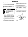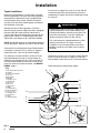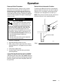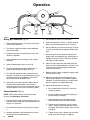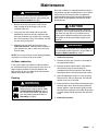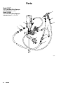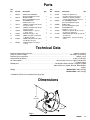
1
Instructions – Parts List
President 10:1 Ratio
Air Spray System
FOR SPRAYING HEAVY FLUIDS FROM 55 GAL. (208
liter) DRUMS
1800 psi (126 bar) Maximum Working Pressure
180 psi (12.6 bar) Maximum Air Input Pressure
Model 225877
Includes Pump, Evenflo Control, Air Supply Hose, Spray Gun, and 100
ft (30 m) Air Atomizing and Fluid Hoses.
Model 225886
Has 25 ft (8 m) hoses,
otherwise same as 225877.
Read warnings and instructions.
See page 2 for table of contents.
GRACO INC.ąP.O. BOX 1441ąMINNEAPOLIS, MNą55440-1441
Copyright 1955, Graco Inc. is registered to I.S. EN ISO 9001
306402F
Table of Contents
Warnings . . . . . . . . . . . . . . . . . . . . . . . . . . . . . . . . . . . . . .
Installation . . . . . . . . . . . . . . . . . . . . . . . . . . . . . . . . . . . . .
Operation . . . . . . . . . . . . . . . . . . . . . . . . . . . . . . . . . . . . .
Maintenance . . . . . . . . . . . . . . . . . . . . . . . . . . . . . . . . . . .
2
5
7
9
Parts . . . . . . . . . . . . . . . . . . . . . . . . . . . . . . . . . . . . . . . .
Technical Data . . . . . . . . . . . . . . . . . . . . . . . . . . . . . . . .
Warranty . . . . . . . . . . . . . . . . . . . . . . . . . . . . . . . . . . . . .
Graco Information . . . . . . . . . . . . . . . . . . . . . . . . . . . . .
10
11
12
12
Symbols
Warning Symbol
Caution Symbol
WARNING
CAUTION
This symbol alerts you to the possibility of serious
injury or death if you do not follow the instructions.
This symbol alerts you to the possibility of damage to
or destruction of equipment if you do not follow the
instructions.
WARNING
EQUIPMENT MISUSE HAZARD
Equipment misuse can cause the equipment to rupture or malfunction and result in serious injury.
D This equipment is for professional use only.
D Read all instruction manuals, tags, and labels before operating the equipment.
D Use the equipment only for its intended purpose. If you are not sure, call your Graco distributor.
D Do not alter or modify this equipment.
D Check equipment daily. Repair or replace worn or damaged parts immediately.
D Do not exceed the maximum working pressure stated on the equipment or in the Technical Data
for your equipment. Do not exceed the maximum working pressure of the lowest rated component
in your system.
D Use fluids and solvents which are compatible with the equipment wetted parts. Refer to the Technical Data section of all equipment manuals. Read the fluid and solvent manufacturer’s warnings.
D Handle hoses carefully. Do not pull on hoses to move equipment.
D Route hoses away from traffic areas, sharp edges, moving parts, and hot surfaces. Do not expose
Graco hoses to temperatures above 66_C (150_F) or below –40_C (–40_F).
D Wear hearing protection when operating this equipment.
D Do not move or lift pressurized equipment.
D Comply with all applicable local, state, and national fire, electrical, and safety regulations.
2
306402
WARNING
INJECTION HAZARD
Spray from the gun, leaks or ruptured components can inject fluid into your body and cause extremely
serious injury, including the need for amputation. Fluid splashed in the eyes or on the skin can also
cause serious injury.
D Fluid injected into the skin is a serious injury. The injury may look like just a cut, but it is a serious
injury. Get immediate medical attention.
D Do not point the gun at anyone or at any part of the body.
D Do not put your hand or fingers over the spray tip.
D Do not stop or deflect leaks with your hand, body, glove or rag.
D Do not “blow back” fluid; this is not an air spray system.
D Always have the tip guard and the trigger guard on the gun when spraying.
D Check the gun diffuser operation weekly. Refer to the gun manual.
D Be sure the gun trigger safety operates before spraying.
D Lock the gun trigger safety when you stop spraying.
D Follow the Pressure Relief Procedure on page 7 if the spray tip clogs and before cleaning,
checking or servicing the equipment.
D Tighten all fluid connections before operating the equipment.
D Check the hoses, tubes, and couplings daily. Replace worn, damaged, or loose parts immediately.
Permanently coupled hoses cannot be repaired; replace the entire hose.
MOVING PARTS HAZARD
Moving parts can pinch or amputate your fingers.
D Keep clear of all moving parts when starting or operating the pump.
D Before checking or servicing the equipment, follow the Pressure Relief Procedure on page 7 to
prevent the equipment from starting unexpectedly.
306402
3
WARNING
FIRE AND EXPLOSION HAZARD
Improper grounding, poor ventilation, open flames or sparks can cause a hazardous condition and result in a fire or explosion and serious injury.
D Ground the equipment and the object being sprayed. Refer to Grounding on page 5.
D If there is any static sparking or you feel an electric shock while using this equipment, stop spraying immediately. Do not use the equipment until you identify and correct the problem.
D Provide fresh air ventilation to avoid the buildup of flammable fumes from solvents or the fluid
being sprayed.
D Keep the spray area free of debris, including solvent, rags, and gasoline.
D Before operating this equipment, electrically disconnect all equipment in the spray area.
D Before operating this equipment, extinguish all open flames or pilot lights in the spray area.
D Do not smoke in the spray area.
D Do not turn on or off any light switch in the spray area while spraying or while operating if fumes
are present.
D Do not operate a gasoline engine in the spray area.
TOXIC FLUID HAZARD
Hazardous fluid or toxic fumes can cause serious injury or death if splashed in the eyes or on the skin,
inhaled, or swallowed.
D Know the specific hazards of the fluid you are using.
D Store hazardous fluid in an approved container. Dispose of hazardous fluid according to all local,
state and national guidelines.
D Always wear protective eyewear, gloves, clothing and respirator as recommended by the fluid and
solvent manufacturer.
4
306402
Installation
General Information
NOTE: Reference numbers and letters in parentheses
in the text refer to the callouts in the figures and the
parts drawing.
NOTE: Always use Genuine Graco Parts and Accessories, available from your Graco distributor.
Grounding
WARNING
FIRE AND EXPLOSION HAZARD
Before operating the pump, ground the
system as explained below. Also read
the section FIRE OR EXPLOSION HAZARD on page 4.
4. Spray gun or dispensing valve: ground through
connection to a properly grounded fluid hose and
pump.
5. Object being sprayed: follow your local code.
6. Solvent pails used when flushing: follow your local
code. Use only metal pails, which are conductive,
placed on a grounded surface. Do not place the
pail on a nonconductive surface, such as paper or
cardboard, which interrupts the grounding continuity.
7. To maintain grounding continuity when flushing or
relieving pressure, hold a metal part of the spray
gun firmly to the side of a grounded metal pail,
then trigger the gun.
1. Pump: use a ground wire and clamp as shown in
Fig. 1. Loosen the grounding lug locknut (W) and
washer (X). Insert one end of a 12 ga (1.5 mm@)
minimum ground wire (Y) into the slot in lug (Z)
and tighten the locknut securely. Connect the other
end of the wire to a true earth ground. Order part
number 222011 Grounding Clamp and Wire.
X
Z
Y
2. Air and fluid hoses: use only electrically conductive
hoses.
W
3. Air compressor: follow manufacturer’s recommendations.
0720
Fig. 1
306402
5
Installation
On the main air supply line, install an air line filter (B)
to remove harmful dirt and contaminants from your
compressed air supply. Also install a bleed-type master
air valve (A).
Typical Installation
Mount the Evenflo Control (1) to the pump, using the
screws supplied with it to attach the mounting plate to
the pump base. Remove the screw and lockwasher
from the bottom of the control. Position the control
over the small hole of the mounting plate and reinstall
the lockwasher and screw.
WARNING
Remove the cover of the supply drum. Place the
Sturdi-Clamp (3) over the edge of the drum and tighten
the tee handle (M) screw securely. Loosen the Uclamp. Lower the pump through the U-clamp until the
pump intake is about 1 in. off the bottom of the drum.
Tighten the clamp wing nuts (N). See Detail A below.
A bleed-type master air valve (A) is required in your
system to reduce the risk of serious bodily injury,
including fluid injection, splashing in the eyes, and
injury from moving parts, if you are adjusting or
repairing the pump. Order Part No. 107142
This valve relieves air trapped between the valve
and the pump after the air supply is shut off.
Trapped air may cause the pump to cycle unexpectedly. Locate the valve within easy access of
the pump.
NOTE: Use thread sealer on all male threads except at
swivel connections. Swivels must remain free to move.
Connect the air and fluid hoses to the Evenflo Control
and the gun as shown in Fig. 2 and Fig. 4. Tape the
hoses every 18 in. (457 mm) for easier handling.
Connect the air hose (12*†) from the 1/2 npt(f) Evenflo
swivel air inlet to the main air supply line. Then connect the hose’s ground wire (C) to a true earth ground.
For automatic air motor lubrication, install an air line
lubricator between the pump air inlet and hose (E).
Otherwise, just connect the 18 in. (457 mm) hose (E)
from the Evenflo Control to the swivel air inlet of the
pump. For manual air motor lubrication, see MAINTENANCE, page 9.
Key
A Bleed-type Master Air Valve
B Air Filter
C Air Hose Ground Wire
E 18” Hose
M Tee-Handle
N Wing Nut
1 Evenflo Control
3 Sturdi-Clamp
5 3/4” Union
6 3/8” Union
7 Swivel Union
8 Nipple
9 1” ID Fluid Hose
10 3/4” ID Fluid Hose
11 3/4 x 1” Union
12 Air Supply Hose
13 Gun Air Hose
14 Pump
15 Hand Spray Gun
Ground the pump as explained on page 5.
B
A
C
12
15
5
6
E
14
10
8
7
9
13
11
1
Detail A
3
05958
Fig. 2
6
306402
M
05959
N
Operation
Pressure Relief Procedure
Relax-A-Valve Automatic Position
With the Evenflo control, its bypass valve, and the
pump Relax-A-Valve properly set, fluid pressure is
relieved from the pump and hose each time you release the gun trigger. Always engage the gun trigger
safety when you stop spraying. To relieve air pressure,
close the Evenflo regulators and open the bleed-type
master air valve.
To set the pump Relax-A-Valve (G) in the automatic
position, loosen the locknut (H), turn the T-handle (J)
clockwise as far as possible, and then back-off the
handle four turns and tighten the nut. See Fig. 3.
NOTE: Every time you resume spraying, ensure that
the Relax-A-Valve is in the automatic position.
WARNING
G
INJECTION HAZARD
If you suspect that the Evenflo system is
not properly set, or that pressure is not
fully relieved, the system pressure must
be manually relieved to prevent the system from
starting or spraying accidentally. Fluid under high
pressure can be injected through the skin and
cause serious injury. To reduce the risk of an injury
from injection, splashing fluid, or moving parts, follow the Pressure Relief Procedure whenever you:
D
D
D
D
H
J
are instructed to relieve the pressure,
stop spraying,
check or service any of the system equipment,
or install or clean the spray tips.
Drain back tube
1. Close the air regulators.
05960
2. Open the bleed-type master air valve.
3. Hold a metal part of the gun firmly to the side of a
grounded metal pail, and trigger the gun to relieve
pressure.
Fig. 3
4. Lock the gun trigger safety.
5. Carefully loosen a fluid hose fitting and relieve
pressure gradually.
If you suspect that the spray tip or hose is completely
clogged, or that pressure has not been fully relieved
after following the steps above, very slowly loosen the
tip guard retaining nut or hose end coupling and relieve
pressure gradually, then loosen completely. Now clear
the tip or hose.
306402
7
Operation
K
G
J
F
E
9
L
13
12
1
Fig. 4
Mixing by Circulation (Fig. 4)
4. Set the Relax-A-Valve (G) to automatic.
1. Close the Evenflo bypass valve (K) by turning the
valve handle clockwise.
5. Open the Evenflo ball valve (L) (handle parallel to
body), and the bleed-type master air valve (A).
2. Turn both air regulator handles counterclockwise
to the free position.
6. Set the atomizing air pressure to the gun at 40 psi
(2.8 bar) by turning the left regulator handle clockwise.
3. Disconnect the gun air atomizing hose (13*) from
the left air regulator.
4. Open the Relax-A-Valve handle (J) fully counterclockwise.
5. Open the bleed-type master air valve (A).
6. Turn the left regulator handle clockwise until air
bleeds slightly through the open union (F).
7. Turn the right regulator handle clockwise to start
the pump. Increase the air pressure until the pump
circulates fluid through the Relax-A-Valve return
(drain back) tube at the desired rate.
8. After mixing, turn both regulator handles counterclockwise to the free position, connect the air
atomization hose (13*) to the left regulator, and set
the pump Relax-A-Valve in the automatic position.
Pump Operation (Fig. 4)
NOTE: Fluid can be mixed by circulating it before
spraying. See Mixing by Circulation.
1. Engage the gun trigger safety. Remove the gun air
cap; this prevents fluid from being forced back into
the gun’s air passages.
2. Turn the Evenflo bypass valve (K) fully in to close
it.
3. Set both regulators in the free position by turning
the handles fully counterclockwise.
8
306402
7. Direct the gun back into the drum. Release the
trigger safety and trigger the gun. Set the right air
regulator to 30 psi (2.1 bar). The pump will operate, filling the hose and gun.
8. Adjust the right regulator to the lowest pressure
necessary for the desired delivery rate; this varies
according to the fluid being pumped and other
system characteristics.
9. Release the gun trigger, engage the trigger safety,
and install the air cap.
10. Release the trigger safety and trigger the gun.
Adjust the left regulator until the fluid is properly
atomized. To minimize overspray, use the lowest
pressure necessary for good atomization.
11. Adjust the Evenflo bypass valve (K).
a. Be sure the Relax-A-Valve (G) is set in the
automatic position.
b. Be sure regulated air pressure is being supplied to the gun and pump.
c.
Open the bypass valve (K) four full turns
counterclockwise from the closed position.
d. Trigger the gun, directing the spray into the
drum. If the pump does not operate, release
the trigger and close the bypass valve 1/4 turn
clockwise.
e. Trigger the gun again. Repeat step d until the
pump starts when the gun is triggered.
Maintenance
WARNING
To reduce the risk of serious injury whenever you
are instructed to relieve pressure, always follow the
Pressure Relief Procedure on page 7.
1. Remove and clean the strainer in the Evenflo
body, add light oil to the screen cavity and reassemble every day.
2. If the pump was not flushed and has not been
operated for more than one day, disconnect the
spray gun fluid hose, turn on the pump, and pump
out a small quantity of fluid. This removes any fluid
that has set-up in the hose.
3. Whenever you are done spraying for the day,
relieve the pressure. Cover the drum to protect it
from contaminants and air, which may cause the
fluid to harden.
NOTE: Be sure you flush the system thoroughly before
any fluid has a chance to set-up or harden.
Flush with a fluid that is compatible with the fluid you
are pumping and with the wetted parts in your system.
Check with your fluid manufacturer or supplier for
recommended flushing fluids and flushing frequency.
Always flush the pump before fluid dries on the displacement rod.
CAUTION
Never leave water or water-base fluid in the pump
overnight. If you are pumping water-base fluid, flush
with water first, then with a rust inhibitor such as
mineral spirits. Relieve the pressure, but leave the
rust inhibitor in the pump to protect the parts from
corrosion.
WARNING
To reduce the risk of serious injury whenever you
are instructed to relieve pressure, always follow the
Pressure Relief Procedure on page 7.
1. Relieve the pressure.
Air Motor Lubrication
2. Remove the spray gun and clean it according to
the supplied instructions.
If your system does not include an automatic lubricator, remove the hose (E) to the pump air inlet. Place 15
drops of light machine oil in the inlet. Reattach the
hose and turn on the air to blow the oil into the motor.
Repeat this process every day.
3. Remove the pump from the drum. Wipe excess
fluid off of the pump. Place the pump in a
grounded metal flushing container, with enough
compatible solvent for flushing the entire system.
Flushing
4. Open the bleed-type master air valve, the pump
Relax-A-Valve, and start the pump. Circulate the
solvent for at least 15 minutes.
WARNING
FIRE AND EXPLOSION HAZARD
Before flushing, read the section FIRE
OR EXPLOSION HAZARD on page 4.
Be sure the entire system and flushing
pails are properly grounded. Refer to
Grounding on page 5.
5. Close the Relax-A-Valve. DIrect the fluid hose into
the fluid supply drum. Start the pump. When the
solvent appears at the hose end, quickly transfer
the hose to the flushing pail and allow the pump to
circulate solvent through the pump and hose until
clean.
6. Relieve the pressure.
306402
9
Parts
Model 225877
10:1 President Paint Sprayer
Includes items 1, 3–15
15
Model 225886
10:1 President Paint Sprayer
Includes items 1, 3, 14–19
5
6
13
14
8
12
7
1
10
3
11
9
05956
10
306402
Parts
Ref
No.
Part No.
Description
1
202844
“EVEN-FLO” CONTROL
See manual 306479 for parts
STURDI-CLAMP
See manual 306305 for parts
ACCESSORY KIT
includes items 5–13
. UNION, str adapter; 3/4 npt (f) x
3/4 npt (f) swivel
. UNION, str adapter; 3/8 npt (f) x
3/8 npt (f) swivel
. UNION, adapter; 1” npt (f) x
1” npt (f) swivel
. NIPPLE, hex pipe; 1” npt
. HOSE, fluid; cpld 1” npt (mbe)
1” ID 50 ft (15 m)lg
. HOSE, fluid; cpld 3/4 not (mbe)
3/4 ID, 50 ft (15 m) lg
. UNION, adapter; 3/4 npt (f) x
1” npt (f)
3
203156
4
203458
5
156172
6
156173
7
158383
8
9
10
11
158585
218986
218689
202966
Qty.
Ref
No.
Part No.
Description
12
214951
13
214653
14
205628
15
204000
16
203461
. HOSE, air; cpld 3/4 x 1/2
npt (mbe) 3/4” ID; 25 ft (8m) lg
. HOSE, air; cpld 3/8 npt (mbe)
1/2” ID; 100 ft (30 m) lg, static free
10:1 PRESIDENT PUMP
See manual 306726 for parts
SPRAY GUN
See manual 306494 for parts
ACCESSORY KIT
includes 5, 6, 12, 17–19
. HOSE, air; cpld 3/8 npt (m). 1/2” ID;
25 ft (8 m) lg, static free
. HOSE, fluid; cpld 3/4 npt (m), 3/4” ID;
25 ft (8 m) lg
. COUPLING, 1” npt (m) x 3/4 npt (f)
swivel
1
1
1
1
1
17
214655
1
1
18
215240
1
19
202965
Qty.
1
1
1
1
1
1
1
1
1
Technical Data
Maximum fluid working pressure . . . . . . . . . . . . . . . . . . . . . . . . . . . . . . . . . . . . . . . . . . . . . . . . . . . . . . . . 1800 psi (126 bar)
Pump air pressure range . . . . . . . . . . . . . . . . . . . . . . . . . . . . . . . . . . . . . . . . . . . . . . . . . . . . . . . . . 40–180 psi (2.8–12 bar)
Maximum gun air pressure . . . . . . . . . . . . . . . . . . . . . . . . . . . . . . . . . . . . . . . . . . . . . . . . . . . . . . . . . . . . . . . 100 psi (7 bar)
Continuous duty delivery . . . . . . . . . . . . . . . . . . . . . . . . . . . . . . . . . . . . . . . . . . . . . . . . . . . . . . . . . . . . . 3 gpm (11 liter/min)
Air Consumption** . . . . . . . . . . . . . . . . . . . . . . . . . . . . . . . . . . . . . . . . . . . . 10.8 cfm (0.3 m#/min) at 1 gpm (3.8 liter/min)
at 70 psi (5 bar)
Wetted parts . . . . . . . . . . . . . . . . . . . . . . . . . . . . . . . . . . . . . . . . . . . . . . . 416 Stainless Steel, Nitralloy, Tungsten Carbide
Steel, Aluminum, Copper, Buna-N, Nitrile Rubber
Leather
Weight . . . . . . . . . . . . . . . . . . . . . . . . . . . . . . . . . . . . . . . . . . . . . . . . . . . . . . . . . . . . . . . . . . . Model 225877 182 lb (83 Kg)
Model 225886 95 lb (43 Kg)
**Additional CFM of air is required for the spray gun.
Dimensions
48.7”
(1221 mm)
20”
(506 mm)
Fig. 5
306402
11
Graco Standard Warranty
Graco warrants all equipment manufactured by Graco and bearing its name to be free from defects in material and workmanship on the
date of sale by an authorized Graco distributor to the original purchaser for use. With the exception of any special, extended, or limited
warranty published by Graco, Graco will, for a period of twelve months from the date of sale, repair or replace any part of the equipment
determined by Graco to be defective. This warranty applies only when the equipment is installed, operated and maintained in accordance with Graco’s written recommendations.
This warranty does not cover, and Graco shall not be liable for general wear and tear, or any malfunction, damage or wear caused by
faulty installation, misapplication, abrasion, corrosion, inadequate or improper maintenance, negligence, accident, tampering, or substitution of non–Graco component parts. Nor shall Graco be liable for malfunction, damage or wear caused by the incompatibility of
Graco equipment with structures, accessories, equipment or materials not supplied by Graco, or the improper design, manufacture,
installation, operation or maintenance of structures, accessories, equipment or materials not supplied by Graco.
This warranty is conditioned upon the prepaid return of the equipment claimed to be defective to an authorized Graco distributor for
verification of the claimed defect. If the claimed defect is verified, Graco will repair or replace free of charge any defective parts. The
equipment will be returned to the original purchaser transportation prepaid. If inspection of the equipment does not disclose any defect
in material or workmanship, repairs will be made at a reasonable charge, which charges may include the costs of parts, labor, and
transportation.
THIS WARRANTY IS EXCLUSIVE, AND IS IN LIEU OF ANY OTHER WARRANTIES, EXPRESS OR IMPLIED, INCLUDING BUT
NOT LIMITED TO WARRANTY OF MERCHANTABILITY OR WARRANTY OF FITNESS FOR A PARTICULAR PURPOSE.
Graco’s sole obligation and buyer’s sole remedy for any breach of warranty shall be as set forth above. The buyer agrees that no other
remedy (including, but not limited to, incidental or consequential damages for lost profits, lost sales, injury to person or property, or any
other incidental or consequential loss) shall be available. Any action for breach of warranty must be brought within two (2) years of the
date of sale.
Graco makes no warranty, and disclaims all implied warranties of merchantability and fitness for a particular purpose in connection
with accessories, equipment, materials or components sold but not manufactured by Graco. These items sold, but not manufactured
by Graco (such as electric motors, switches, hose, etc.), are subject to the warranty, if any, of their manufacturer. Graco will provide
purchaser with reasonable assistance in making any claim for breach of these warranties.
In no event will Graco be liable for indirect, incidental, special or consequential damages resulting from Graco supplying equipment
hereunder, or the furnishing, performance, or use of any products or other goods sold hereto, whether due to a breach of contract,
breach of warranty, the negligence of Graco, or otherwise.
FOR GRACO CANADA CUSTOMERS
The parties acknowledge that they have required that the present document, as well as all documents, notices and legal proceedings
entered into, given or instituted pursuant hereto or relating directly or indirectly hereto, be drawn up in English. Les parties reconnaissent avoir convenu que la rédaction du présente document sera en Anglais, ainsi que tous documents, avis et procédures judiciaires
exécutés, donnés ou intentés à la suite de ou en rapport, directement ou indirectement, avec les procedures concernées.
Graco Information
TO PLACE AN ORDER, contact your Graco distributor, or call one of the following numbers
to identify the distributor closest to you:
1–800–367–4023 Toll Free
612–623–6921
612–378–3505 Fax
All written and visual data contained in this document reflects the latest product information available at the time of publication.
Graco reserves the right to make changes at any time without notice.
Sales Offices: Minneapolis, Detroit
International Offices: Belgium, Korea, Hong Kong, Japan
www.graco.com
PRINTED IN USA 306402 12/1955, Revised 10/2003
12
306402