1
2.
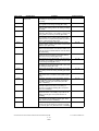
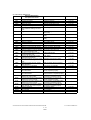
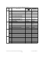
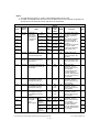
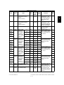
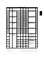
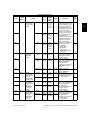
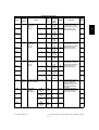
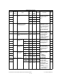
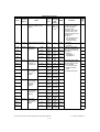
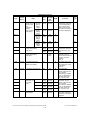
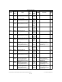
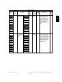
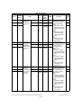
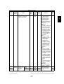
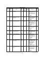
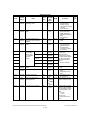
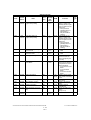
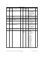
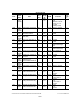
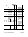
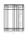
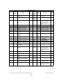
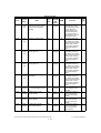
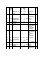
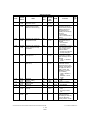
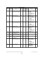
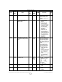
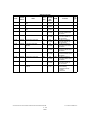
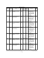
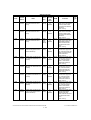
ERROR CODE AND SELF-DIAGNOSTIC MODE
2.1
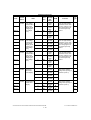
Error Code List
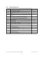
The following error codes is displayed at the upper right of the screen when the CLEAR PAPER or CALL
SERVICE symbol is blinking.
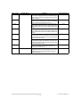
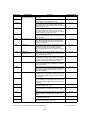
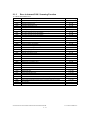
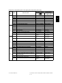
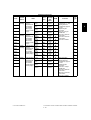
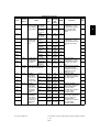
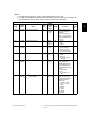
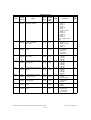
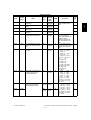
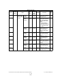
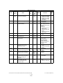
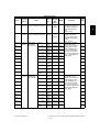
2.1.1
Jam
Error code
Contents
Troubleshooting
E010
Paper exit jam
Classification
Jam not reaching the exit sensor : The paper which
has passed through the fuser unit does not reach
the exit sensor.
P. 5-1
E020
Paper exit jam
Stop jam at the exit sensor: The trailing edge of the
paper does not pass the exit sensor after its leading
edge has reached this sensor.
P. 5-2
E030
Other paper jam
Power-ON jam: The paper is remaining on the
paper transport path when power is turned ON.
P. 5-18
E061
Incorrect paper size setting for upper drawer: The
size of paper in the 1st drawer differs from size setting of the equipment.
P. 5-18
E062
Incorrect paper size setting for lower drawer: The
size of paper in the 2nd drawer differs from size setting of the equipment.
P. 5-18
E063
Incorrect paper size setting for PFP upper drawer:
The size of paper in the 3rd drawer differs from size
setting of the equipment.
Incorrect paper size setting for PFP lower drawer:
The size of paper in the 4th drawer differs from size
setting of the equipment.
Incorrect paper size setting for bypass tray: The
size of paper in the bypass tray differs from size
setting of the equipment.
Image data delay jam: Image data to be printed
cannot be prepared.
P. 5-18
E064
E065
E090
© June 2005 TOSHIBA TEC
P. 5-18
P. 5-18
P. 5-19
e-STUDIO281c/351c/451c ERROR CODE AND SELF-DIAGNOSTIC MODE
2-1
2
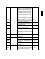
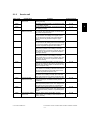
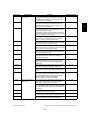
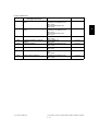
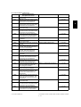
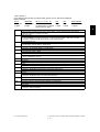
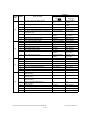
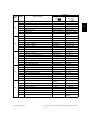
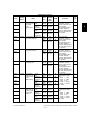
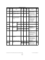
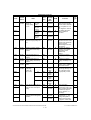
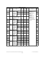
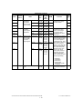
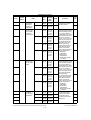
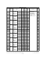
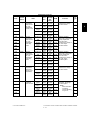
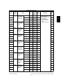
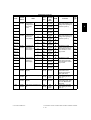
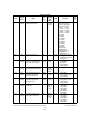
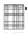
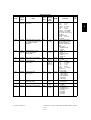
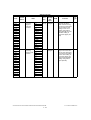
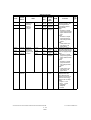
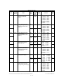
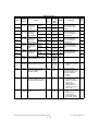
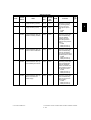
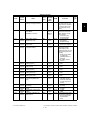
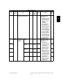
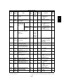
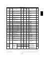
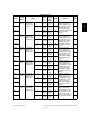
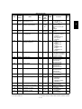
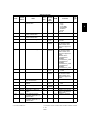
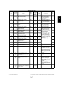
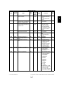
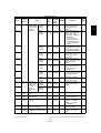
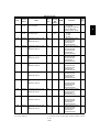
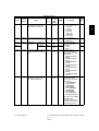
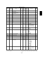
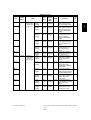
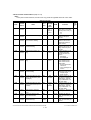
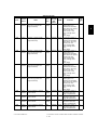
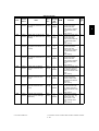
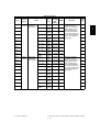
Error code
Contents
Troubleshooting
ADU misfeeding (Paper not reaching the registration sensor): The paper which has passed through
ADU does not reach the registration sensor during
duplex printing.
P. 5-3
E120
Bypass misfeeding (Paper not reaching the registration sensor): The paper fed from the bypass tray
does not reach the registration sensor.
P. 5-4
E130
Upper drawer misfeeding (Paper not reaching the
upper drawer feed sensor): The paper fed from the
upper drawer does not reach the upper drawer feed
sensor.
P. 5-5
E140
Lower drawer misfeeding (Paper not reaching the
lower drawer feed sensor): The paper fed from the
lower drawer does not reach the lower drawer feed
sensor.
PFP upper drawer misfeeding (Paper not reaching
the PFP upper drawer feed sensor): The paper fed
from the PFP upper drawer does not reach the PFP
upper drawer feed sensor.
P. 5-6
E160
PFP lower drawer misfeeding (Paper not reaching
the PFP lower drawer feed sensor): The paper fed
from the PFP lower drawer does not reach the PFP
lower drawer feed sensor.
P. 5-8
E190
LCF misfeeding (Paper not reaching the LCF feed
sensor): The paper fed from the LCF does not
reach the LCF feed sensor.
P. 5-9
Upper drawer transport jam (Paper not reaching the
registration sensor): The paper does not reach the
registration sensor after it has passed the upper
drawer feed sensor.
P. 5-10
E110
Classification
Paper misfeeding
E150
E200
Paper transport jam
e-STUDIO281c/351c/451c ERROR CODE AND SELF-DIAGNOSTIC MODE
2-2
P. 5-7
© June 2005 TOSHIBA TEC
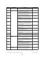
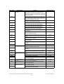
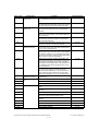
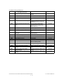
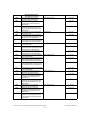
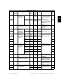
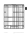
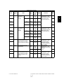
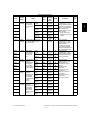
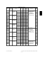
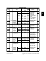
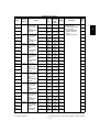
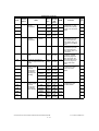
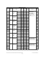
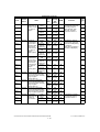
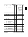
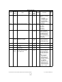
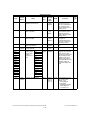
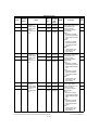
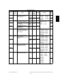
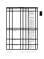
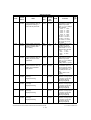
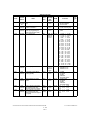
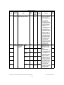
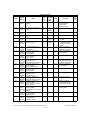
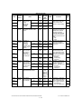
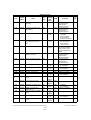
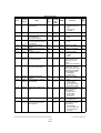
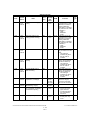
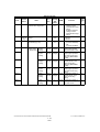
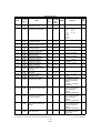
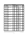
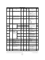
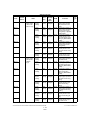
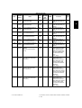
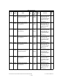
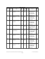
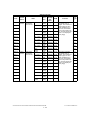
Error code
Contents
Troubleshooting
Lower drawer transport jam (Paper not reaching the
registration sensor): The paper does not reach the
registration sensor after it has passed the upper
drawer feed sensor.
P. 5-10
E220
Lower drawer transport jam (Paper not reaching the
upper drawer feed sensor): The paper does not
reach the upper drawer feed sensor after it has
passed the lower drawer feed sensor.
P. 5-11
E300
PFP upper drawer transport jam (Paper not reaching the registration sensor): The paper does not
reach the registration sensor after it has passed the
upper drawer feed sensor.
PFP upper drawer transport jam (Paper not reaching the upper drawer feed sensor): The paper does
not reach the upper drawer feed sensor after it has
passed the lower drawer feed sensor.
P. 5-10
E320
PFP upper drawer transport jam (Paper not reaching the lower drawer feed sensor): The paper does
not reach the lower drawer feed sensor after it has
passed the PFP upper drawer feed sensor.
P. 5-12
E330
PFP lower drawer transport jam (Paper not reaching the registration sensor): The paper does not
reach the registration sensor after it has passed the
upper drawer feed sensor.
P. 5-10
E340
PFP lower drawer transport jam (Paper not reaching the upper drawer feed sensor): The paper does
not reach the upper drawer feed sensor after it has
passed the lower drawer feed sensor.
P. 5-11
E350
PFP lower drawer transport jam (Paper not reaching the lower drawer feed sensor): The paper does
not reach the lower drawer feed sensor after it has
passed the PFP upper drawer feed sensor.
PFP lower drawer transport jam (Paper not reaching the PFP upper drawer feed sensor): The paper
does not reach the PFP upper drawer feed sensor
after it has passed the PFP lower drawer feed sensor.
P. 5-12
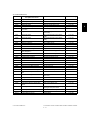
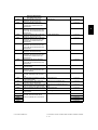
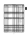
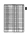
Jam access cover open jam: The jam access cover
has opened during printing.
P. 5-20
Front cover open jam: The front cover has opened
during printing.
P. 5-20
PFP side cover open jam: The PFP side cover has
opened during printing.
P. 5-21
ADU open jam: The ADU has opened during printing.
Side cover open jam: The side cover has opened
during printing.
LCF side cover open jam: The LCF side cover has
opened during printing.
Bridge unit open jam: The bridge unit has opened
during printing.
P. 5-21
Jam not reaching the ADU entrance sensor: The
paper does not reach the ADU entrance sensor
after it is switchbacked in the exit section.
Stop jam in the ADU: The paper does not reach the
ADU exit sensor after it has passed the ADU
entrance sensor.
P. 5-14
E210
Classification
Paper transport jam
E310
E360
E400
Cover open jam
E410
E420
Cover open jam
E430
E440
E450
E480
E510
Paper transport jam
(ADU section)
E520
© June 2005 TOSHIBA TEC
P. 5-11
P. 5-13
P. 5-22
P. 5-22
P. 5-23
P. 5-15
e-STUDIO281c/351c/451c ERROR CODE AND SELF-DIAGNOSTIC MODE
2-3
2
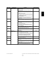
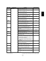
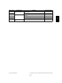
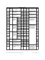
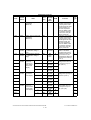
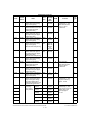
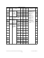
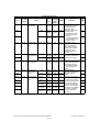
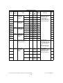
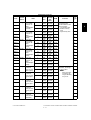
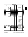
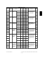
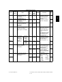
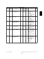
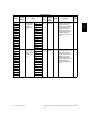
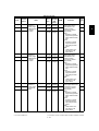
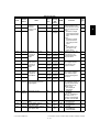
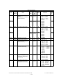
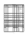
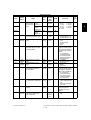
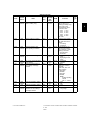
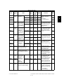
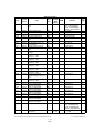
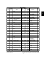
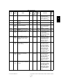
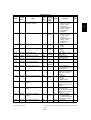
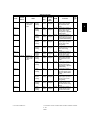
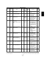
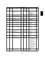
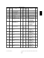
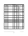
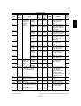
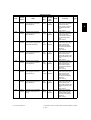
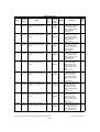
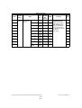
Error code
Contents
Troubleshooting
E550
Other paper jam
Classification
Paper remaining jam on the transport path: The
paper is remaining on the transport path when printing is finished (caused by a multiple paper feeding).
P. 5-19
E712
RADF jam
Jam not reaching the original registration sensor:
The original fed from the original feeding tray does
not reach the original registration sensor.
P. 5-24
E713
Cover open jam in the read ready status: Jam
caused by opening of the RADF jam access cover
or front cover while the RADF is waiting for the
scanning start signal from the equipment.
P. 5-24
E714
Feed signal reception jam: The feed signal is
received even no original exists on the original
feeding tray.
P. 5-25
E721
Jam not reaching the read sensor: The original
does not reach the read sensor after it has passed
the registration sensor (when scanning obverse
side) or the reverse sensor (when scanning reverse
side).
Jam not reaching the original exit/reverse sensor
(during scanning): The original which passed the
read sensor does not reach the original exit/reverse
sensor when it is transported from the scanning
section to exit section.
P. 5-25
E724
Stop jam at the original registration sensor: The
trailing edge of the original does not pass the original registration sensor after its leading edge has
reached this sensor.
P. 5-26
E725
Stop jam at the read sensor: The trailing edge of the
original does not pass the read sensor after its leading edge has reached this sensor.
P. 5-27
E731
Stop jam at the original exit/reverse sensor: The
trailing edge of the original does not pass the original exit/reverse sensor after its leading edge has
reached this sensor.
RADF jam access cover open: The RADF jam
access cover has opened during RADF operation.
P. 5-27
RADF open jam: RADF has opened during RADF
operation.
P. 5-28
Jam at the bridge unit transport sensor 1: The
paper does not reach the bridge unit transport sensor 1 after it has passed the exit sensor.
P. 5-29
Stop jam at the bridge unit transport sensor 1: The
trailing edge of the paper does not pass the bridge
unit transport sensor 1 after its leading edge has
reached the sensor.
Jam at the bridge unit transport sensor 2: The trailing edge of the paper does not reach the bridge unit
transport sensor 2 after its leading edge has
reached the bridge unit transport sensor 1.
P. 5-29
Stop jam at the bridge unit transport sensor 2: The
trailing edge of the paper does not pass the bridge
unit transport sensor 2 after its leading edge has
reached the bridge unit transport sensor 2.
P. 5-29
Punching jam: Punching is not performed properly.
[MJ-1023/1024 (when MJ-6004 is installed)]
[MJ-1101 (when MJ-6101 is installed)]
P. 5-46
E722
E860
E870
E910
Finisher jam
(Bridge unit)
E920
E930
E940
E9F0
Finisher jam
(Punch unit)
e-STUDIO281c/351c/451c ERROR CODE AND SELF-DIAGNOSTIC MODE
2-4
06/08
P. 5-26
P. 5-27
P. 5-29
© June 2005 TOSHIBA TEC
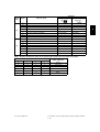
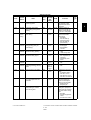
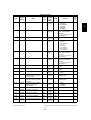
Error code
EA10
Classification
Finisher jam
(Finisher section)
Contents
Troubleshooting
Paper transport delay jam: The paper which has
passed the bridge
unit does not reach the inlet sensor. [MJ-1022/
1023/1024/1101]
P. 5-30
Paper transport stop jam:
(1) The paper does not pass through the inlet sensor.
[MJ-1022/1023/1024]
(2) The paper has passed through the inlet sensor
but does not reach or pass the feed path sensor
or processing tray sensor.
[MJ-1023/1024]
(3) The paper which has passed through the inlet
sensor does not reach the transport sensor.
[MJ-1101]
P. 5-32
EA21
Paper size error jam: Paper does not reach the sensor because the paper is shorter than spec. [MJ1101]
P. 5-33
EA30
Power-ON jam:
(1) Paper exists at the inlet sensor when power is
turned ON.
[MJ-1022/1023/1024]
(2) Paper exists at the feed path sensor or processing tray sensor when power is turned ON.
[MJ-1023/1024]
P. 5-34
EA31
Transport path paper remaining jam: The paper
which has passed through the inlet sensor does not
reach the transport sensor. [MJ-1101]
P. 5-35
EA32
Exit paper remaining jam: The paper is remaining
on the finishing tray when the power is turned ON.
[MJ-1101]
P. 5-35
Door open jam:
1) The finisher has been released from the equipment during printing. [MJ-1022]
2) The upper/front cover of the finisher section or
the upper/ front door of the puncher section has
opened during printing. [MJ-1023/1024]
3) The front cover or stationary tray cover is
opened during paper transport. [MJ-1101]
Stapling jam: Stapling is not performed properly.
[MJ-1022/1023/1024/1101]
Early arrival jam: The inlet sensor detects the paper
earlier than a specified timing. [MJ-1022/1023/
1024/1101]
Stack delivery jam: It cannot deliver the stack of
paper on the intermediary process tray to the stack
tray. [MJ-1022]
P. 5-36
EA20
EA40
Finisher jam
(Finisher section)
EA50
EA60
EA70
2
P. 5-38
P. 5-40
P. 5-41
Stack exit belt home position error: The stack exit
belt is not at the home position. [MJ-1101]
© June 2005 TOSHIBA TEC
e-STUDIO281c/351c/451c ERROR CODE AND SELF-DIAGNOSTIC MODE
2-5
06/08
Error code
EA80
Classification
Contents
Troubleshooting
Stapling jam: Stapling is not performed properly.
[MJ-1024]
P. 5-43
Door open jam: The delivery cover or inlet cover
has opened dur-ing printing [MJ-1024].
P. 5-43
EAA0
Power-ON jam: Paper exists at No.1 paper sensor,
No. 2 paper sensor, No.3 paper sensor, vertical
path paper sensor or delivery sensor when power is
turned ON. [MJ-1024]
P. 5-44
EAB0
Transport stop jam: The paper which passed
through the inlet sensor does not reach or pass
No.1 paper sensor, No. 2 paper sensor, No.3 paper
sensor or delivery sensor. [MJ-1024]
P. 5-44
EAC0
Transport delay jam: The paper which has reached
the inlet sensor does not pass through the inlet sensor. [MJ-1024]
P. 5-45
EA90
Finisher jam
(Saddle stitcher section)
EAD0
Other paper jam
Print end command time-out jam: The printing has
not finished normally because of the communication error between the SYS board and LGC board
at the end of printing.
P. 5-47
EAE0
Finisher jam
Receiving time time-out jam: The printing has been
interrupted because of the communication error
between the equipment and finisher when the
paper is transported from the equipment to the finisher.
P. 5-47
EAF0
Finisher jam
(Finisher section)
Stack return jam: It cannot load the paper which
passed through the delivery roller on the intermediary process tray. [MJ-1022]
P. 5-42
EB30
Finisher jam
Ready time time-out jam: The equipment judges
that the paper transport to the finisher is disabled
because of the communication error between the
equipment and finisher at the start of printing.
P. 5-47
EB50
Paper transport jam
Paper remaining on the transport path: The multiple
feeding of preceding paper caused the misfeeding
of upcoming paper.
P. 5-16
Paper remaining on the transport path: The multiple
feeding of preceding paper caused the misfeeding
of upcoming paper (redetection after no jam is
detected at [EB50]).
P. 5-17
Sideways adjustment motor (M2) home position
detection error: The Sideways adjustment motor is
not at the home position. [MJ-1101 (when MJ-6101
is installed)]
Skew adjustment motor (M1) home position detection abnormality: The Skew adjustment motor is not
at the home position. [MJ-1101 (when MJ-6101 is
installed)]
P. 5-48
ED12
Shutter home position error: The shutter is not at
the home position. [MJ-1101]
P. 5-49
ED13
Front alignment plate home position error: The front
alignment plate is not at the home position. [MJ1101]
P. 5-49
ED14
Rear alignment plate home position error: The rear
alignment plate is not at the home position. [MJ1101]
P. 5-50
ED15
Paddle home position error: The paddle is not at the
home position. [MJ-1101]
P. 5-50
ED16
Buffer tray home position error: The buffer tray is
not at the home position. [MJ-1101]
P. 5-51
EB60
ED10
ED11
Finisher jam
e-STUDIO281c/351c/451c ERROR CODE AND SELF-DIAGNOSTIC MODE
2-6
06/08
P. 5-48
© June 2005 TOSHIBA TEC
2.1.2
Service call
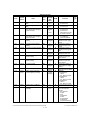
Error code
C010
Classification
Contents
Troubleshooting
Main motor abnormality: The main motor is not
rotating normally.
P. 5-52
C020
Developer motor abnormality: The developer motor
is not rotating normally.
P. 5-52
C030
Transport motor abnormality: The transport motor is
not rotating normally.
P. 5-52
PFP motor abnormality: The PFP motor is not rotating normally. (the case that paper can be fed from
any drawer except the PFP)
P. 5-53
Upper drawer tray abnormality: The upper drawer
tray-up motor is not rotating or the upper drawer
tray is not moving normally. (the case that paper
can be fed from any drawer except the upper
drawer)
Lower drawer tray abnormality: The lower drawer
tray-up motor is not rotating or the lower drawer tray
is not moving normally. (the case that paper can be
fed from any drawer except the lower drawer)
P. 5-54
C150
PFP upper drawer tray abnormality: The PFP upper
drawer tray-up motor is not rotating or the PFP
upper drawer tray is not moving normally. (the case
that paper can be fed from any drawer except the
PFP upper drawer)
P. 5-55
C160
PFP lower drawer tray abnormality: The PFP lower
drawer tray-up motor is not rotating or the PFP
lower drawer tray is not moving normally. (the case
that paper can be fed from any drawer except the
PFP lower drawer)
P. 5-55
C180
LCF tray-up motor abnormality: The LCF tray-up
motor is not rotating or the LCF tray is not moving
normally. (the case that paper can be fed from any
drawer except the LCF)
LCF end fence motor abnormality: The LCF end
fence motor is not rotating or the LCF end fence is
not moving normally. (the case that paper can be
fed from any drawer except the LCF)
P. 5-56
LCF transport motor abnormality: The LCF transport motor is not rotating normally. (the case that
paper can be fed from any drawer except the LCF)
P. 5-58
Peak detection error: Lighting of the exposure lamp
(white reference) is not detected when power is
turned ON.
P. 5-59
C270
Carriage home position sensor not turning OFF
within a specified period of time: The carriage does
not shift from its home position in a specified time.
P. 5-59
C280
Carriage home position sensor not turning ON
within a specified period of time: The carriage does
not reach to its home position in a specified period
of time.
P. 5-59
Charger cleaner motor abnormality: Charger
cleaner motor is not rotating or wire cleaner is not
moving normally.
P. 5-89
C040
Drive system related
service call
Paper feeding system
related service call
C130
C140
C1A0
C1B0
C260
C360
Scanning system
related service call
Copy process related
service call
© June 2005 TOSHIBA TEC
P. 5-54
P. 5-57
e-STUDIO281c/351c/451c ERROR CODE AND SELF-DIAGNOSTIC MODE
2-7
2
Error code
Classification
Contents
Troubleshooting
C411
Fuser unit related service call
Thermistor or heater abnormality at power-ON:
Abnormality of the thermistor is detected when
power is turned ON or the temperature of the fuser
roller does not rise in a specified period of time after
power is turned ON.
P. 5-60
C412
Thermistor/heater abnormality at power-ON: Thermistor abnormality is detected at power-ON or the
fuser roller temperature does not rise within a specified period of time after power-ON.
P. 5-60
C443
Heater abnormality after abnormality judgment (not
reaching to intermediate temperature)
P. 5-61
C445
Heater abnormality after abnormality judgment
(pre-running end temperature abnormality)
P. 5-61
C446
Heater abnormality after abnormality judgment
(pre-running end temperature abnormality)
P. 5-61
C447
Heater abnormality after abnormality judgment
(temperature abnormality at ready status)
P. 5-61
C449
Heater abnormality after abnormality judgment
(overheating)
P. 5-61
C471
IH power voltage abnormality or IH initial abnormality
(IH board initial abnormality)
P. 5-61
C472
IH power voltage abnormality (power supply abnormality)
P. 5-61
C475
IH power voltage abnormality (power supply abnormality when door is opened)
P. 5-61
C480
Overheating of IGBT: The temperature of the IGBT
rises abnormally.
P. 5-61
C490
IH control circuit or IH coil abnormality: Abnormality
is detected in IH control circuit or IH coil is broken/
shorted.
P. 5-62
C4B0
C550
Fuser unit counter abnormality
Optional communicaRADF I/F error: Communication error has occurred
tion related service call between the RADF and the scanner.
P. 5-62
P. 5-63
C570
Communication error between Engine-CPU and
IPC board
P. 5-63
C580
Communication error between IPC board and finisher
P. 5-63
Connection error between SYS board and LGC
board
P. 5-64
C940
C950
Engine-CPU abnormality
LGC board memory abnormality
P. 5-64
P. 5-64
C960
Connection error between LGC board and DRV
board, ID abnormality
P. 5-64
C900
Circuit related service
call
C970
Process related service call
High-voltage transformer abnormality: Leakage of
the main charger is detected.
P. 5-89
C9E0
Circuit related service
call
Connection error between SLG board and SYS
board, ID abnormality
P. 5-65
CA10
Laser optical unit
related service call
Polygonal motor abnormality: The polygonal motor
is not rotating normally.
P. 5-66
H-Sync detection error: H-Sync signal detection PC
board cannot detect laser beams.
P. 5-66
CA20
e-STUDIO281c/351c/451c ERROR CODE AND SELF-DIAGNOSTIC MODE
2-8
© June 2005 TOSHIBA TEC
Error code
Contents
Troubleshooting
Entrance motor abnormality: The entrance motor is
not rotating normally. [MJ-1101]
P. 5-67
CB11
Buffer tray guide motor abnormality: The buffer tray
guide motor is not rotating or the buffer tray guide is
not moving normally. [MJ-1101]
P. 5-67
CB12
Buffer roller drive motor abnormality: The buffer
roller drive motor is not rotating or the buffer roller is
not moving normally. [MJ-1101]
P. 5-67
CB20
Delivery motor abnormality: Delivery motor or delivery roller is not rotating normally. [MJ-1022]
P. 5-68
CB30
Tray 1/Tray 2 shift motor abnormality: Tray 1/Tray 2
shift motor is not rotating or delivery tray is not moving normally. [MJ-1023/1024]
P. 5-68
Movable tray shift motor abnormality: The movable
tray shift motor is not rotating or the movable tray is
not moving normally. [MJ-1101]
P. 5-68
CB31
Movable tray paper-full detection error: The actuator of the movable tray paper-full detection sensor
does not move smoothly. [MJ-1101]
P. 5-69
CB40
Rear aligning plate motor abnormality: Rear aligning plate motor is not rotating or aligning plate is not
moving normally. [MJ-1023/1024]
P. 5-69
Front alignment motor abnormality: The front alignment motor is not rotating or the front alignment
plate is not moving normally. [MJ-1101]
P. 5-69
Staple motor abnormality: Staple motor is not rotating or stapler is not moving normally. [MJ-1022/
1023/1024]
P. 5-70
Stapler home position error: The stapler home position sensor does not work. [MJ-1101]
P. 5-70
CB51
Stapler shift home position error: The stapler is not
at the home position. [MJ-1101]
P. 5-70
CB60
Stapler shift motor abnormality: Stapler shift motor
is not rotating or staple unit is not moving normally.
[MJ-1023/1024/1101]
P. 5-71
CB80
Backup RAM data abnormality:
1) Abnormality of checksum value on finisher controller PC board is detected when the power is
turned ON. [MJ-1023/1024]
2) Abnormality of checksum value on punch controller PC board is detected when the power is
turned ON. [MJ-1023/1024 (when MJ-6004 is
installed)]
P. 5-71
RAM abnormality: Abnormality of checksum value
on finisher controller PC board is detected when the
power is turned on. [MJ-1101]
P. 5-71
CB81
Flash ROM abnormality: Abnormality of checksum
value on finisher controller PC board is detected
when the power is turned on. [MJ-1101]
P. 5-72
CB90
Paper pushing plate motor abnormality: Paper
pushing plate motor is not rotating or paper pushing
plate is not moving normally. [MJ-1024]
P. 5-72
CBA0
Stitch motor (front) abnormality: Stitch motor (front)
is not rotating or rotary cam is not moving normally.
[MJ-1024]
P. 5-72
CBB0
Stitch motor (rear) abnormality: Stitch motor (rear)
is not rotating or rotary cam is not moving normally.
[MJ-1024]
P. 5-72
CB10
Classification
Finisher related
service call
CB50
© June 2005 TOSHIBA TEC
e-STUDIO281c/351c/451c ERROR CODE AND SELF-DIAGNOSTIC MODE
2-9
06/08
2
Error code
Contents
Troubleshooting
Alignment motor abnormality: Alignment motor is
not rotating or aligning plate is not moving normally.
[MJ-1024]
P. 5-72
CBD0
Guide motor abnormality: Guide motor is not rotating or guide is not moving normally. [MJ-1024]
P. 5-73
CBE0
Paper folding motor abnormality: Paper folding
motor or paper folding roller is not rotating normally.
[MJ-1024]
P. 5-73
CBF0
Paper positioning plate motor abnormality: Paper
positioning plate motor is not rotating or paper positioning plate is not moving normally. [MJ-1024]
P. 5-73
CC00
Sensor connector abnormality: Connector of guide
home position sensor, paper pushing plate home
position sensor or paper pushing plate top position
sensor is disconnected. [MJ-1024]
P. 5-74
CC10
Micro switch abnormality: With all covers closed,
inlet door switch, delivery door switch or front cover
switch is open. [MJ-1024]
P. 5-74
CC20
Communication error between finisher and saddle
stitcher: Communication error between finisher controller PC board and saddle stitcher controller board
[MJ-1023/1024]
Stack processing motor abnormality: The stack processing motor is not rotating or the stack delivery
belt is not moving normally. [MJ-1022]
Stack transport motor abnormality: The stack transport motor is not rotating or the stack transport belt
is not moving normally. [MJ-1101]
P. 5-74
CC31
Transport motor abnormality: The transport motor is
not rotating or the stack transport roller -1 and -2 is
not rotating normally. [MJ-1101]
P. 5-76
CC40
Swing motor abnormality: Swing motor is not rotating or swing unit is not moving normally. [MJ-1023/
1024]
P. 5-76
CC41
Paper holder cam home position abnormality: The
paper holder cam is not at the home position. [MJ1101]
P. 5-77
CC50
Horizontal registration motor abnormality: Horizontal registration motor is not rotating or puncher is
not shifting normally. [MJ-1023/1024 (when MJ6004 is installed)]
P. 5-77
CC51
Sideways adjustment motor (M2) abnormality:
Sideways adjustment motor is not rotating or
puncher is not shifting normally. [MJ-1101 (when
MJ-6101 is installed)
P. 5-77
CC52
Skew adjustment motor (M1) abnormality: Skew
adjustment motor is not rotating or puncher is not
shifting normally. [MJ-1101 (when MJ-6101 is
installed)]
Punch motor abnormality: Punch motor is not rotating or puncher is not shifting normally. [MJ-1023/
1024 (when MJ-6004 is installed)]
Punch motor (M3) home position detection error:
Punch motor is not rotating or puncher is not shifting normally. [MJ-1101 (when MJ-6101 is installed)]
P. 5-78
CBC0
CC30
CC60
CC61
Classification
Finisher related
service call
e-STUDIO281c/351c/451c ERROR CODE AND SELF-DIAGNOSTIC MODE
2 - 10
06/08
P. 5-75
P. 5-76
P. 5-78
P. 5-79
© June 2005 TOSHIBA TEC
Error code
Contents
Troubleshooting
Punch ROM checksum error: Abnormality of checksum value on Hole punch controller PC board is
detected when the power is turned on. [MJ-1101
(when MJ-6101 is installed)]
P. 5-79
CC72
Punch RAM read/write error: Abnormality of checksum value on Hole punch controller PC board is
detected when the power is turned on. [MJ-1101
(when MJ-6101 is installed)]
P. 5-79
CC80
Front alignment motor abnormality: Front alignment
motor is not rotating or front aligning plate is not
moving normally. [MJ-1022]
Front aligning plate motor abnormality: Front aligning plate motor is not rotating or aligning plate is not
moving normally. [MJ-1023/1024]
P. 5-80
Rear alignment motor abnormality: The rear alignment motor is not rotating or the rear alignment
plate is not moving normally. [MJ-1101]
P. 5-80
CC90
Upper stack tray lift motor abnormality: The upper
stack tray lift motor is not rotating or the upper stack
tray is not moving normally. [MJ-1022]
P. 5-81
CCA0
Lower stack tray lift motor abnormality: The lower
stack tray lift motor is not rotating or the lower stack
tray is not moving normally. [MJ-1022]
P. 5-82
CCB0
Rear jogging motor abnormality: The rear jogging
motor is not rotating or the rear jogging plate is not
moving normally. [MJ-1022]
P. 5-82
CCD0
Stack ejection motor abnormality: Stack ejection
motor or stack ejection roller is not rotating normally. [MJ-1023/1024]
P. 5-83
CCE0
Paper trailing edge assist motor abnormality: Paper
trailing edge assist motor is not rotating or paper
trailing edge assist is not moving normally. [MJ1023/1024]
P. 5-83
CCF0
Gear changing motor abnormality: Gear changing
motor is not rotating normally. [MJ-1023/1024]
P. 5-83
CDE0
Paddle motor abnormality: The paddle motor is not
rotating or the paddle is not rotating normally. [MJ1101]
P. 5-84
CE00
Communication error between finisher and punch
unit: Communication error between finisher controller PC board and punch controller PC board [MJ1023/1024 (when MJ-6004 is installed)]
[MJ-1101 (when MJ-6101 is installed)]
P. 5-84
Image quality sensor abnormality (OFF level): The
output value of this sensor is out of a specified
range when sensor light source is OFF.
P. 5-85
CE20
Image quality sensor abnormality (no pattern level):
The output value of this sensor is out of a specified
range when the image quality control test pattern is
not formed.
P. 5-86
CE40
Image quality control test pattern abnormality: The
test pattern is not formed normally.
P. 5-87
CE50
Temperature/humidity sensor abnormality: The output value of this sensor is out of a specified range.
P. 5-88
CE90
Drum thermistor abnormality: The output value of
the drum thermistor is out of a specified range.
P. 5-88
CC71
CE10
Classification
Finisher related
service call
Image control related
service call
© June 2005 TOSHIBA TEC
e-STUDIO281c/351c/451c ERROR CODE AND SELF-DIAGNOSTIC MODE
2 - 11
06/08
2
Error code
CEA0
Classification
Copy process related
service call
Contents
Troubleshooting
Revolver home position detection abnormality: It
cannot detect that the revolver is at its home position.
P. 5-89
Black developer unit lifting movement abnormality:
The black developer unit does not move up or down
normally (lifting cam does not operate normally).
P. 5-90
2nd transfer roller position detection abnormality:
The 2nd transfer roller does not contact/release
normally.
P. 5-91
CEE0
Transfer belt position detection abnormality (normal
speed): The home position of the transfer belt cannot be detected.
P. 5-92
CEE1
Transfer belt position detection abnormality (when
decelerating): Reference position of the transfer
belt cannot be detected.
P. 5-92
CEF0
Revolver motor abnormality: Revolver motor is not
rotating or revolver is not moving normally.
P. 5-92
Toner density detection voltage abnormality: The
output value of the color auto-toner sensor in printing is out of a specified range.
P. 5-93
Reference plate detection voltage abnormality: The
output value of the color auto-toner sensor against
the reference plate is out of a specified range at the
light amount correction during an auto-toner adjustment or when a print job has finished.
Light amount correction voltage abnormality: The
light amount correction is not finished normally during an auto-toner adjustment or when a print job
has finished, or the output value of the sensor is out
of a specified range when the light amount correction has finished.
P. 5-94
Color auto-toner sensor abnormality: The connection of the color auto-toner sensor cannot be
detected at the initialization, or the output value of
color auto-toner sensor when the revolver starts
rotating for initialization is out of a specified range.
P. 5-96
P. 5-63
CEB0
CEC0
CF20
Copy process related
service call
Toner density control
related service call
CF30
CF40
CF50
P. 5-95
F070
Communication
related service call
Communication error between System-CPU and
Engine-CPU
F090
Circuit related service
call
SRAM abnormality on the SYS board
P. 5-65
NVRAM abnormality on the SYS board
P. 5-65
SRAM and NVRAM abnormality on the SYS board
P. 5-65
Other service call
HDD format error: HDD cannot be initialized normally.
P. 5-97
HDD unmounted: Connection of HDD cannot be
detected.
HDD start error: HDD cannot become Ready state.
P. 5-97
F103
HDD transfer time-out: Reading/writing cannot be
performed in the specified period of time.
P. 5-97
F104
HDD data error: Abnormality is detected in the data
of HDD.
P. 5-97
F105
HDD other error
P. 5-97
F091
F092
F100
F101
F102
P. 5-97
F106
Point and Print partition damage
P. 5-97
F107
/BOX partition damage
P. 5-97
F108
/SHA partition damage
P. 5-97
e-STUDIO281c/351c/451c ERROR CODE AND SELF-DIAGNOSTIC MODE
2 - 12
© June 2005 TOSHIBA TEC
Error code
F110
Classification
Contents
Troubleshooting
Communication error between System-CPU and
Scanner-CPU
P. 5-63
P. 5-63
P. 5-97
F130
Scanner response abnormality
Database abnormality: Database is not operating
normally.
Invalid MAC address
F200
Data overwrite kit (GP-1060) is taken off
P. 5-98
SLG board abnormality
P. 5-65
F111
F120
F350
Communication
related service call
Other service call
Circuit related service
call
© June 2005 TOSHIBA TEC
P. 5-97
e-STUDIO281c/351c/451c ERROR CODE AND SELF-DIAGNOSTIC MODE
2 - 13
05/11
2
2.1.3
Error in Internet FAX / Scanning Function
1) Internet FAX related error
Error code
Classification
Troubleshooting
1C10
System access abnormality
P. 5-98
1C11
Insufficient memory
P. 5-98
1C12
Message reception error
P. 5-98
1C13
1C14
Message transmission error
Invalid parameter
P. 5-98
P. 5-98
1C15
Exceeding file capacity
P. 5-98
1C20
System management module access abnormality
P. 5-98
1C21
Job control module access abnormality
P. 5-98
1C22
Job control module access abnormality
P. 5-98
1C30
1C31
Directory creation failure
File creation failure
P. 5-99
P. 5-99
1C32
File deletion failure
P. 5-98
1C33
File access failure
P. 5-99
1C40
Image conversion abnormality
P. 5-99
1C60
1C61
HDD full failure during processing
Address Book reading failure
P. 5-99
P. 5-99
1C62
Memory acquiring failure
P. 5-99
1C63
Terminal IP address unset
P. 5-99
1C64
Terminal mail address unset
P. 5-99
1C65
SMTP address unset
P. 5-99
1C66
Server time time-out error
P. 5-99
1C67
1C68
NIC time time-out error
NIC access error
P. 5-99
P. 5-99
1C69
SMTP server connection error
P. 5-99
1C6A
HOST NAME error
P. 5-99
1C6B
Terminal mail address error
P. 5-100
1C6C
Destination mail address error
P. 5-100
1C6D
1C70
System error
SMTP client OFF
P. 5-99
P. 5-100
1C71
SMTP authentication error
P. 5-100
1C72
POP before SMTP error
P. 5-100
1C80
Internet FAX transmission failure when processing E-mail job received
P. 5-100
1C81
1C82
Onramp Gateway transmission failure
Internet FAX transmission failure when processing FAX job received
P. 5-100
P. 5-100
1CC0
Job canceling
-
1CC1
Power failure
P. 5-100
e-STUDIO281c/351c/451c ERROR CODE AND SELF-DIAGNOSTIC MODE
2 - 14
© June 2005 TOSHIBA TEC
2) RFC related error
Error code
Message displayed in
the TopAccess screen
Contents
Troubleshooting
2500
Syntax error, command unrecognized
HOST NAME error(RFC: 500)
Destination mail address error
(RFC: 500)
Terminal mail address error
(RFC: 500)
P. 5-101
2501
Syntax error in parameters or arguments
HOST NAME error(RFC: 501)
Destination mail address error
(RFC: 501)
Terminal mail address error
(RFC: 501)
P. 5-101
2503
Bad sequence of commands
Destination mail address error
(RFC: 503)
P. 5-101
2504
2551
User not local
2552
Insufficient system storage
2553
Mailbox name not allowed
HOST NAME error
(RFC: 504)
Destination mail address error
(RFC: 550)
Destination mail address error
(RFC: 551)
Terminal/Destination mail address
error
(RFC: 552)
Destination mail address error
(RFC: 553)
P. 5-101
2550
Command parameter not implemented
Mailbox unavailable
© June 2005 TOSHIBA TEC
P. 5-101
P. 5-101
P. 5-101
P. 5-101
e-STUDIO281c/351c/451c ERROR CODE AND SELF-DIAGNOSTIC MODE
2 - 15
2
3) Electronic Filing related error
Error code
Message displayed in
the TopAccess screen
Contents
Troubleshooting
2B10
There was no applicable job.
No applicable job error in job control
module
P. 5-102
2B11
Job status failed.
JOB status abnormality
P. 5-102
2B20
2B30
Failed to access file.
Insufficient disk space.
P. 5-102
P. 5-102
2B31
Failed to access Electronic Filing.
2B32
Failed to print Electronic Filing document.
File library function error
Insufficient disk space in /BOX partition
Status of specified Electronic Filing
or folder is undefined or being created/deleted
Electronic Filing printing failure:
Specified document can not be
printed because of clients access
(being edited, etc.).
2B50
2B51
Failed to process image.
Failed to process print image.
Image library error
List library error
P. 5-102
P. 5-102
2B71
Document(s) expire(s) in a few days
Documents expiring in a few days
exist
-
2B80
Hard Disk space for Electronic Filing
nearly full.
Hard disk space in /BOX partition is
nearly full (90%).
-
P. 5-102
P. 5-102
2B90
Insufficient Memory.
Insufficient memory capacity
P. 5-102
2BA0
Invalid Box password specified.
Invalid Box password
P. 5-102
2BB0
Job canceled
Job canceling
-
2BB1
Power failure occurred
Power failure
P. 5-102
2BC0
2BC1
System fatal error.
Failed to acquire resource.
P. 5-102
P. 5-102
2BD0
Power failure occurred during e-Filing restoring.
Fatal failure occurred
System management module
resource acquiring failure
Power failure occurred during restoring of Electronic Filing
2BE0
Failed to get machine parameter.
Machine parameter reading failure
P. 5-103
2BF0
Maximum number of page range is
reached.
Exceeding maximum number of
pages
P. 5-103
2BF1
Maximum number of document
range is reached.
Exceeding maximum number of documents
P. 5-103
2BF2
Maximum number of folder range is
reached.
Exceeding maximum number of folders
P. 5-103
e-STUDIO281c/351c/451c ERROR CODE AND SELF-DIAGNOSTIC MODE
2 - 16
P. 5-102
© June 2005 TOSHIBA TEC
4) E-mail related error
Error code
Message displayed in
the TopAccess screen
Contents
Troubleshooting
2C10
Illegal Job status
System access abnormality
P. 5-104
2C11
Not enough memory
Insufficient memory
P. 5-104
2C12
2C13
Illegal Job status
Illegal Job status
Message reception error
Message transmission error
P. 5-104
P. 5-104
2C14
Invalid parameter specified
Invalid parameter
P. 5-104
2C15
Message size exceeded limit or max- Exceeding file capacity
imum size
P. 5-104
2C20
Illegal Job status
System management module access
abnormality
P. 5-104
2C21
Illegal Job status
Job control module access abnormality
P. 5-104
2C22
Illegal Job status
Job control module access abnormality
P. 5-104
2C30
Failed to create directory
Directory creation failure
P. 5-104
2C31
2C32
Failed to create file
Failed to delete file
File creation failure
File deletion failure
P. 5-104
P. 5-104
2C33
Failed to create file
File access failure
P. 5-104
2C40
Failed to convert image file format
Image conversion abnormality
P. 5-104
2C60
Failed to process your Job. Insufficient disk space.
HDD full failure during processing
P. 5-104
2C61
Failed to read AddressBook
Address Book reading failure
P. 5-104
2C62
2C63
Not enough memory
Invalid Domain Address
Memory acquiring failure
Terminal IP address unset
P. 5-104
P. 5-104
2C64
Invalid Domain Address
Terminal mail address unset
P. 5-105
2C65
Failed to connect to SMTP server
SMTP address unset
P. 5-105
2C66
Failed to connect to SMTP server
Server time time-out error
P. 5-105
2C67
Failed to send E-Mail message
NIC time time-out error
P. 5-105
2C68
2C69
Failed to send E-Mail message
Failed to connect to SMTP server
NIC access error
SMTP server connection error
P. 5-105
P. 5-105
2C6A
Failed to send E-Mail message
HOST NAME error (No RFC error)
P. 5-105
2C6B
Invalid address specified in From:
field
Terminal mail address error
P. 5-105
2C6C
Invalid address specified in To: field
Destination mail address error (No
RFC error)
P. 5-105
2C6D
NIC system error
System error
P. 5-105
2C70
SMTP service is not available
SMTP client OFF
P. 5-105
2C71
2C72
Failed SMTP Authentication
POP Before SMTP Authentication
Failed
SMTP authentication error
POP before SMTP error
P. 5-105
P. 5-105
2C80
Failed to process received E-mail job E-mail transmission failure when processing E-mail job received
P. 5-105
P. 5-105
2C81
Failed to process received Fax job
Process failure of FAX job received
2CC0
Job canceled
Job canceling
-
2CC1
Power failure occurred
Power failure
P. 5-106
© June 2005 TOSHIBA TEC
e-STUDIO281c/351c/451c ERROR CODE AND SELF-DIAGNOSTIC MODE
2 - 17
2
5) File sharing related error
2D20
Message displayed in
the TopAccess screen
Illegal Job status
Not enough memory
Illegal Job status
Illegal Job status
Invalid parameter specified
There are too many documents in the
folder. Failed in creating new document.
Illegal Job status
2D21
Illegal Job status
2D22
Illegal Job status
2D30
2D31
2D32
2D33
2D40
2D60
2D62
Failed to create directory
Failed to create file
Failed to delete file
Failed to create file
Failed to convert image file format
Failed to copy file
Failed to connect to network destination. Check destination path
Specified network path is invalid.
Check destination path
Logon to file server failed. Check
username and password
There are too many documents in the
folder. Failed in creating new document.
Failed to process your Job. Insufficient disk space.
FTP service is not available
File Sharing service is not available
Expired scan documents deleted
from share folder.
Expired Sent Fax documents deleted
from shared folder.
Expired Received Fax documents
deleted from shared folder.
Scanned documents in shared folder
deleted upon users request.
Sent Fax Documents in shared folder
deleted upon users request.
Received Fax Documents in shared
folder deleted upon users request.
Failed to delete file.
Failed to acquire resource.
Job canceled
Power failure occurred
Error code
2D10
2D11
2D12
2D13
2D14
2D15
2D63
2D64
2D65
2D66
2D67
2D68
2DA0
2DA1
2DA2
2DA3
2DA4
2DA5
2DA6
2DA7
2DC0
2DC1
Contents
Troubleshooting
System access abnormality
Insufficient memory
Message reception error
Message transmission error
Invalid parameter
Exceeding document number
P. 5-107
P. 5-107
P. 5-107
P. 5-107
P. 5-107
P. 5-107
System management module access
abnormality
Job control module access abnormality
Job control module access abnormality
Directory creation failure
File creation failure
File deletion failure
File access failure
Image conversion abnormality
File library access abnormality
File server connection error
P. 5-107
P. 5-107
P. 5-107
P. 5-107
P. 5-107
P. 5-107
P. 5-107
P. 5-107
Invalid network path
P. 5-107
Login failure
P. 5-108
Exceeding documents in folder:
Creating new document is failed.
P. 5-108
HDD full failure during processing
P. 5-108
FTP service not available
File sharing service not available
Periodical deletion of scanned documents completed properly.
Periodical deletion of transmitted
FAX documents completed properly.
Periodical deletion of received FAX
documents completed properly.
Manual deletion of scanned documents completed properly.
Manual deletion of transmitted FAX
documents completed properly.
Manual deletion of received FAX
documents completed properly.
File deletion failure
Resource acquiring failure
Job canceling
Power failure
P. 5-108
P. 5-108
-
e-STUDIO281c/351c/451c ERROR CODE AND SELF-DIAGNOSTIC MODE
2 - 18
06/08
P. 5-107
P. 5-107
P. 5-107
P. 5-107
P. 5-108
© June 2005 TOSHIBA TEC
6) E-mail reception related error
Error code
3A10
3A11
3A12
3A20
3A21
3A22
3A30
3A40
3A50
3A51
3A52
3A60
3A61
3A62
3A70
3A80
3A81
3A82
3B10
3B11
3B12
Message displayed in
the TopAccess screen
MIME Error has been detected in the
received mail.
MIME Error has been detected in the
received mail. This mail has been
transferred to the administrator.
MIME Error has been detected in the
received mail. This mail could not be
transferred to the administrator.
Analyze Error has been detected in
the received mail.
Analyze Error has been detected in
the received mail. This mail has been
transferred to the administrator.
Analyze Error has been detected in
the received mail. This mail could not
be transferred to the administrator.
Whole partial mails were not reached
by timeout.
Partial Mail Error has been detected
in the received mail.
HDD Full Error has been occurred in
this mail.
HDD Full Error has been occurred in
this mail. This mail has been transferred to the administrator.
HDD Full Error has been occurred in
this mail. This mail could not be
transferred to the administrator.
HDD Full Warning has been occurred
in this mail.
HDD Full Warning has been occurred
in this mail. This mail could not be
transferred to the administrator.
HDD Full Warning has been occurred
in this mail. This mail could not be
transferred to the administrator.
Receiving partial mail was aborted
since the partial mail setting has
been changed to Disable.
Partial mail was received during the
partial mail setting is disabled.
Partial mail was received during the
partial mail setting is disabled. This
mail has been transferred to the
administrator.
Partial mail was received during the
partial mail setting is disabled. This
mail could not be transferred to the
administrator.
Format Error has been detected in
the received mail.
Format Error has been detected in
the received mail. This mail has been
transferred to the administrator.
Format Error has been detected in
the received mail. This mail could not
be transferred to the administrator.
© June 2005 TOSHIBA TEC
Contents
E-mail MIME error
Troubleshooting
P. 5-109
P. 5-109
P. 5-109
E-mail analysis error
P. 5-109
P. 5-109
P. 5-109
Partial mail time-out error
P. 5-109
Partial mail related error
P. 5-109
Insufficient HDD capacity error
P. 5-109
P. 5-109
P. 5-109
Warning of insufficient HDD capacity
P. 5-109
P. 5-109
P. 5-109
Warning of partial mail interruption
P. 5-109
Partial mail reception setting OFF
P. 5-109
P. 5-109
P. 5-109
E-mail format error
P. 5-109
P. 5-109
P. 5-109
e-STUDIO281c/351c/451c ERROR CODE AND SELF-DIAGNOSTIC MODE
2 - 19
2
Error code
3B20
3B21
3B22
3B30
3B31
3B32
3B40
3B41
3B42
3C10
3C11
3C12
3C13
3C20
3C21
3C22
3C30
3C31
3C32
Message displayed in
the TopAccess screen
Content-Type Error has been
detected in the received mail.
Content-Type Error has been
detected in the received mail. This
mail has been transferred to the
administrator.
Content-Type Error has been
detected in the received mail. This
mail could not be transferred to the
administrator.
Charset Error has been detected in
the received mail.
Charset Error has been detected in
the received mail. This mail has been
transferred to the administrator.
Charset Error has been detected in
the received mail. This mail could not
be transferred to the administrator.
Decode Error has been detected in
the received mail.
Decode Error has been detected in
the received mail. This mail has been
transferred to the administrator.
Decode Error has been detected in
the received mail. This mail could not
be transferred to the administrator.
Tiff Analyze Error has been detected
in the received mail.
Tiff Analyze Error has been detected
in the received mail. This mail has
been transferred to the administrator.
Tiff Analyze Error has been detected
in the received mail. This mail could
not be transferred to the administrator.
Tiff Analyze Error has been detected
in the received mail.
Tiff Compression Error has been
detected in the received mail.
Tiff Compression Error has been
detected in the received mail. This
mail has been transferred to the
administrator.
Tiff Compression Error has been
detected in the received mail. This
mail could not be transferred to the
administrator.
Tiff Resolution Error has been
detected in the received mail.
Tiff Resolution Error has been
detected in the received mail. This
mail has been transferred to the
administrator.
Tiff Resolution Error has been
detected in the received mail. This
mail could not be transferred to the
administrator.
Contents
Content-Type error
Troubleshooting
P. 5-109
P. 5-109
P. 5-109
Charset error
P. 5-109
P. 5-109
P. 5-109
E-mail decode error
P. 5-109
P. 5-109
P. 5-109
TIFF analysis error
P. 5-109
P. 5-109
P. 5-109
P. 5-109
E-mail format error
P. 5-109
P. 5-109
P. 5-109
Content-Type error
P. 5-110
P. 5-110
P. 5-110
e-STUDIO281c/351c/451c ERROR CODE AND SELF-DIAGNOSTIC MODE
2 - 20
© June 2005 TOSHIBA TEC
Error code
3C40
3C41
3C42
3C50
3C51
3C52
3C60
3C61
3C62
3C70
3D10
3D20
3D30
3E10
3E20
3E30
3E40
3F00
3F10
3F20
3F30
3F40
Message displayed in
the TopAccess screen
Tiff Paper Size Error has been
detected in the received mail.
Tiff Paper Size Error has been
detected in the received mail. This
mail has been transferred to the
administrator.
Tiff Paper Size Error has been
detected in the received mail. This
mail could not be transferred to the
administrator.
Offramp Destination Error has been
detected in the received mail.
Offramp Destination Error has been
detected in the received mail. This
mail has been transferred to the
administrator.
Offramp Destination Error has been
detected in the received mail. This
mail could not be transferred to the
administrator.
Offramp Security Error has been
detected in the received mail.
Offramp Security Error has been
detected in the received mail. This
mail has been transferred to the
administrator.
Offramp Security Error has been
detected in the received mail. This
mail could not be transferred to the
administrator.
Power Failure has been occurred in
Email receiving.
SMTP Destination Error has been
detected in the received mail. This
mail was deleted.
Offramp Destination limitation Error
has been detected in the received
mail.
Fax Board Error has been occurred
in the received mail.
POP3 Connection Error has been
occurred in the received mail.
POP3 Connection Timeout Error has
been occurred in the received mail.
POP3 Login Error has been occurred
in the received mail.
POP3 Login Error occurred in the
received mail.
File I/O Error has been occurred in
this mail. The mail could not be
received until File I/O is recovered.
© June 2005 TOSHIBA TEC
Contents
Charset error
Troubleshooting
P. 5-110
P. 5-110
P. 5-110
E-mail decode error
P. 5-110
P. 5-110
P. 5-110
TIFF analysis error
P. 5-110
P. 5-110
P. 5-110
Power failure error
P. 5-110
Destination address error
P. 5-110
Offramp destination limitation error
P. 5-110
FAX board error
P. 5-110
POP3 server connection error
P. 5-110
POP3 server connection time-out
error
POP3 login error
P. 5-110
POP3 login method error
P. 5-110
File I/O error
P. 5-110
P. 5-110
P. 5-110
P. 5-110
P. 5-110
P. 5-110
e-STUDIO281c/351c/451c ERROR CODE AND SELF-DIAGNOSTIC MODE
2 - 21
2
2.1.4
Printer function error
Following codes are displayed at the end of the user name on the print job log screen.
Error code
402F
4031
4032
4033
4034
4035
4036
A221
A222
A290
A291
A292
A2A0
A2A1
A2A2
Contents
Page memory size error - 1200 dpi network print is performed by the equipment with 128 MB (standard) memory.
HDD full during print - Large quantity image data by private print or invalid
network print are saved in HDD.
Private-print-only error: Jobs other than Private print jobs cannot be performed.
Printing data storing limitation error: Printing with its data being stored to the
HDD temporarily (Proof print, Private print, Scheduled print, etc.) cannot be
performed.
e-Filing storing limitation error: Printing with its data being stored to the HDD
(print and e-Filing, print to e-Filing, etc.) cannot be performed.
Local file storing limitation error: Network FAX or Internet FAX cannot be sent
when "Local" is selected for the destination of the file to save.
User authentication error: The user who intended to print a document is not
registered as a user.
Print job cancellation - Print job (copy, list print, network print) is deleted from
the print job screen.
Print job power failure - The power of the equipment is turned OFF during
print job (copy, list print, network print).
Limit over error (Black): The numbers of output pages have exceeded those
specified with both of the department code and the user code at the same
time.
Limit over error (Black): The number of output pages has exceeded the one
specified with the user code.
Limit over error (Black): The number of output pages has exceeded the one
specified with the department code.
Limit over error (Color): The numbers of output pages have exceeded those
specified with both of the department code and the user code at the same
time.
Limit over error (Color): The number of output pages has exceeded the one
specified with the user code.
Limit over error (Color): The number of output pages has exceeded the one
specified with the department code.
e-STUDIO281c/351c/451c ERROR CODE AND SELF-DIAGNOSTIC MODE
2 - 22
Troubleshooting
P. 5-111
P. 5-111
P. 5-111
P. 5-111
P. 5-111
P. 5-111
P. 5-111
P. 5-111
P. 5-111
P. 5-111
P. 5-111
P. 5-111
P. 5-111
P. 5-111
P. 5-111
© June 2005 TOSHIBA TEC
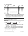
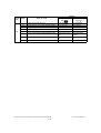
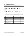
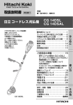
<<Error history>>
In the setting mode (08-253), the latest twenty groups of error data will be displayed.
Display example
EA10
99999999
05 06 14 17 57 32
064
064
23621000000
Error code
Total counter YY MM DD HH MM SS
MMM
NNN
ABCDEFHIJLO
4 digits
8 digits
12 digits (Year is indicated 3 digits
3 digits
11 digits
with its last two digits.)
A
B
C
D
E
F
G
H
I
J
K
L
MMM
NNN
O
Paper source
0: Not selected 1: Bypass feed 2: LCF 3: Upper drawer 4: Lower drawer 5: PFP upper drawer
6: PFP lower drawer 7: Unused 8: Unused
Paper size code
0: A5/ST 1: A5-R 2: ST-R 3: LT, 4: A4 5: B5-R 6: LT-R 7: A4-R 8: OTHER/UNIV 9: B5,
A: FOLIO/COMP B: LG C: B4 D: LD E: A3 F: 13"LG G: Unsed H: A6-R I: Post card J: 8.5"SQ
K: A3-wide L: 305×457 mm M: 8K N: 16K-R O: 16K Z: Not selected
Sort mode/staple mode
0: Non-sort/Non-staple 1: Group 2: Sort 7: Front staple
8: Double staple 9: Rear staple A: Saddle stitch
ADF mode
0: Unused 1: AUTO FEED (SADF) 2: STACK FEED
APS/AMS mode
0: Not selected 1: APS 2: AMS
Duplex mode
0: Not selected 1: Book 2: Double-sided/Single-sided 4: Double-sided/Duplex copying
8: Single-sided/Duplex copying
Unused
Image shift
0: Unused 1: Book 2: Left 4: Right
Editing
0: Unused 1: Masking 2: Trimming 3: Mirror image 4: Unused
Edge erase/Dual-page
0: Unused 1: Edge erase 2: Dual-page 3: Edge erase & Dual-page
Unused
Function
0: Unused 1: Copying 2: FAX/Internet FAX transmission 3: FAX/Internet FAX/E-mail reception printing
4: Unused 5: Printing/List print 6: Scan/E-mail transmission
Primary scanning reproduction ratio (Display in hexadecimal)
(Mx256)+(Mx16)+M
Secondary scanning reproduction ratio (Display in hexadecimal)
(Nx256)+(Nx16)+N
Color mode
0: Auto color 1: Full color 2: Black 3: Unused 4: Twin color copy 5: Gray scale
6: Unused 7: Image smoothing
© June 2005 TOSHIBA TEC
e-STUDIO281c/351c/451c ERROR CODE AND SELF-DIAGNOSTIC MODE
2 - 23
2
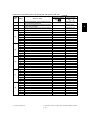
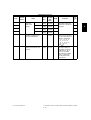
2.2
Self-diagnosis Modes
Mode
For start
Contents
For exit
Display
Control panel
check mode
[0]+[1]+
[POWER]
All LEDs on the control panel are lit, and all
the LCD pixels blink.
[POWER]
OFF/ON
-
Test mode
[0]+[3]+
[POWER]
Checks the status of input/output signals.
[POWER]
OFF/ON
100% C A4
TEST MODE
Test print mode
[0]+[4]+
[POWER]
Outputs the test patterns.
[POWER]
OFF/ON
100% P A4
TEST PRINT
Adjustment
mode
[0]+[5]+
[POWER]
Adjusts various items.
[POWER]
OFF/ON
100% A A4
TEST MODE
Setting mode
[0]+[8]+
[POWER]
Sets various items.
[POWER]
OFF/ON
100% D
TEST MODE
List print mode
[9]+[START]+
[POWER]
Prints out the data lists of the codes 05 and
08, PM support mode and pixel counter.
[POWER]
OFF/ON
100% UA A4
LIST PRINT
PM support
mode
[6]+[START]+
[POWER]
Clears each counter.
[POWER]
OFF/ON
100% K
TEST MODE
Firmware
update mode
[8]+[9]+
[POWER]
Performs updating of the system firmware.
[POWER]
OFF/ON
-
Notes:
1. To enter the desired mode, turn ON the power while two digital keys designated to each mode
(e.g. [0] and [5]) are pressed simultaneously.
2. When the optional FAX unit is installed, Faxes received automatically during the self-diagnosis mode may not be printed out. Be sure to disconnect the modular code from the line connectors (LINE1, LINE2) of the equipment before starting the self-diagnosis mode. Also, be
sure to finish the self-diagnosis mode by turning the power OFF and back ON before connecting the modular code.
To exit from Adjustment mode and Setting mode:
Shut down the equipment. When the power should be turned OFF, be sure to shut down the equipment by pressing the [ENERGY SAVER] button for a few seconds.
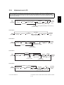
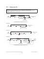
<Operation procedure>
Control panel check mode (01):
ÅðÃÅïÃ
ÅÐÑÉÛÎÃ
ÔÛÜ ´·¬ñ
ÔÝÜ ¾´·²µ·²¹
ÅÍÌßÎÌÃ
øÞ«¬¬±² ½¸»½µ÷
ÅÐÑÉÛÎà ÑÚÚñÑÒ
øÛ¨·¬÷
ÅÍÌßÎÌÃ
Notes:
1. A mode can be canceled by [POWER] OFF/ON when the LED is lit and the LCD is blinking.
2. Button Check
Buttons with LED
(Press to turn OFF the LED.)
Buttons without LED
(Press to display the message on the control panel.)
Button on touch panel
(Press to display the screen on the control panel at power-ON.)
Test mode (03): Refer to 2.2.1. Input check (test mode 03) and 2.2.2. Output check (test mode
03).
Test print mode (04): Refer to 2.2.3. Test print mode (04).
Adjustment mode (05): Refer to 2.2.4. Adjustment mode (05).
Setting mode (08): Refer to 2.2.5. Setting mode (08).
e-STUDIO281c/351c/451c ERROR CODE AND SELF-DIAGNOSTIC MODE
2 - 24
06/08
© June 2005 TOSHIBA TEC
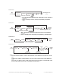
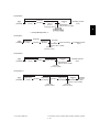
List print mode (9S): The procedure varies depending on the code.
ÅçÃÅÍÌßÎÌÃ
ÅÐÑÉÛÎÃ
øݱ¼»÷
ÅÍÌßÎÌÃ
ÅÜ·¹·¬¿´ µ»§-Ã
ïðïæ ß¼¶«-¬³»²¬ ³±¼» øðë÷
Õ»§ ·² ¬¸» º·®-¬
ïðîæ Í»¬¬·²¹ ³±¼» øðè÷
½±¼» ¬± ¾» °®·²¬»¼
ÅÍÌßÎÌÃ
ÅÜ·¹·¬¿´ µ»§-Ã
Õ»§ ·² ¬¸» ´¿-¬
½±¼» ¬± ¾» °®·²¬»¼
ÅÍÌßÎÌÃ
Ô·-¬ -¬¿®¬- ¬±
¾» °®·²¬»¼
ÅÐÑÉÛÎÃ
ÑÚÚñÑÒ
øÛ¨·¬÷
øݱ¼»÷
ïðíæ ÐÓ -«°°±®¬ ³±¼»
ïðìæ ͬ±®»¼ ·²º±®³¿¬·±² ±º °·¨»´ ½±«²¬»® ø¬±²»® ½¿®¬®·¼¹» ®»º»®»²½»÷
ïðëæ ͬ±®»¼ ·²º±®³¿¬·±² ±º °·¨»´ ½±«²¬»® ø-»®ª·½» ¬»½¸²·½·¿² ®»º»®»²½»÷
ïðêæ Û®®±® ¸·-¬±®§ øÓ¿¨·³«³ ïððð ·¬»³-÷
ïðéæ Û®®±® ¸·-¬±®§ øÔ¿¬»-¬ èð ·¬»³-÷
PM support mode (6S):
ÅêÃÅÍÌßÎÌÃ
ÅÐÑÉÛÎÃ
2
øݱ¼»÷
îæ ÐÓ Í«°°±®¬ ͽ®»»²
ÅÍÌßÎÌÃ
øÑ°»®¿¬·±² -¬¿®¬»¼÷
ÅÐÑÉÛÎà ÑÚÚñÑÒ
øÛ¨·¬÷
Firmware update mode (89): Refer to 6. FIRMWARE UPDATING.
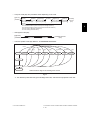
ÅÐÑÉÛÎÃ
ÑÒ
Ò±®³¿´
ÅðÃÅïÃ
É¿®³·²¹ «°
ݱ²¬®±´ °¿²»´
½¸»½µ ³±¼»
ÅðÃÅíÃ
Ì»-¬ ³±¼»
ÅðÃÅìÃ
Ì»-¬ °®·²¬
³±¼»
ÅðÃÅëÃ
ß¼¶«-¬³»²¬
³±¼»
ÅðÃÅèÃ
Í»¬¬·²¹
³±¼»
ÅçÃÅÍÌßÎÌÃ
Ô·-¬ °®·²¬
³±¼»
ÅêÃÅÍÌßÎÌÃ
ÐÓ -«°°±®¬
³±¼»
ÅèÃÅçÃ
Ú·®³©¿®»
«°¼¿¬» ³±¼»
λ¿¼§
ÅÐÑÉÛÎÃ
ÑÚÚ
öï
̱ «-»®
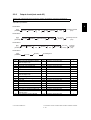
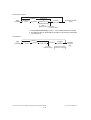
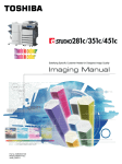
ͬ¿¬» ¬®¿²-·¬·±² ¼·¿¹®¿³ ±º -»´ºó¼·¿¹²±-·- ³±¼»Fig. 2-1
*1 Turn OFF the power after using the self-diagnosis mode, and leave the equipment to the user.
© June 2005 TOSHIBA TEC
e-STUDIO281c/351c/451c ERROR CODE AND SELF-DIAGNOSTIC MODE
2 - 25
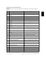
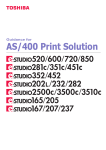
2.2.1
Input check (Test mode 03)
The status of each input signal can be checked by pressing the [FAX] button, [COPY] button and
the digital keys in the test mode (03).
<Operation procedure>
ÅðÃÅíÃ
ÅÐÑÉÛÎÃ
ÅÍÌßÎÌÃ
ÅÚßÈÃ
±®
ÅÝÑÐÇÃ
ÅÜ·¹·¬¿´ µ»§-Ã
øÔÝÜ ÑÒ÷
ÅÝÔÛßÎÃ
ÅÐÑÉÛÎà ÑÚÚñÑÒ
øÛ¨·¬÷
Note:
Initialization is performed before the equipment enters the test mode.
Fig. 2-2 Example of display during input check
Items to be checked and the condition of the equipment when the buttons [A] to [H] are highlighted are
listed in the following pages.
e-STUDIO281c/351c/451c ERROR CODE AND SELF-DIAGNOSTIC MODE
2 - 26
© June 2005 TOSHIBA TEC
[FAX] button: OFF/[COPY] button: OFF ([FAX] LED: OFF/[COPY] LED: OFF)
Digital
key
[1]
[2]
[3]
Button
e.g.
A
Bypass unit connection
B
ADU connection
C
D
LCF connection
Normal display
e.g.
Not connected
Connected
Not connected
Connected
Not connected
Connected
E
-
-
-
F
-
-
-
G
-
-
-
H
LCF drawer detection switch
Drawer not installed
Drawer present
A
B
PFP upper drawer detection switch
-
Drawer not installed
-
Drawer present
-
C
PFP upper drawer paper stock sensor
Paper almost empty
Paper present
D
PFP upper drawer feed sensor
Paper present
No paper
E
PFP connection
Not connected
Connected
F
G
PFP side cover open/close switch
PFP upper drawer empty sensor
Cover opened
No paper
Cover closed
Paper present
H
PFP upper drawer tray-up sensor
A
LCF tray bottom sensor
B
LCF standby side paper misload detection sensor
Tray at upper limit
position
Tray at bottom position
Properly loaded
Other than upper
limit position
Other than upper
limit position
Paper misload
C
-
-
D
-
-
-
E
-
-
-
F
G
-
-
-
-
H
Paper stock sensor at LCF feed side
Paper present
No paper
A
PFP lower drawer detection switch
Drawer not installed
Drawer present
B
[4]
Contents
Highlighted display
Items to check
-
-
-
C
D
PFP lower drawer paper stock sensor
PFP lower drawer feed sensor
Paper almost empty
Paper present
Paper present
No paper
E
Abnormal rotation
Normal rotation
F
PFP motor rotation status (Motor is rotating at
output mode (03))
-
G
PFP lower drawer empty sensor
No paper
Paper present
H
PFP lower drawer tray-up sensor
Tray at upper limit
position
Other than upper
limit position
© June 2005 TOSHIBA TEC
-
-
e-STUDIO281c/351c/451c ERROR CODE AND SELF-DIAGNOSTIC MODE
2 - 27
2
Digital
key
[5]
[6]
[7]
Contents
Button
Items to check
Normal display
e.g.
e.g.
A
LCF end fence home position sensor
Fence home position
Other than home
position
B
LCF end fence stop position sensor
Fence stop position
Other than stop
position
C
Empty sensor at LCF standby side
No paper
Paper present
D
LCF side cover open/close switch
Cover closed
Cover opened
E
LCF motor rotation status (Motor is rotating at
output mode (03))
Abnormal rotation
Normal rotation
F
LCF tray-up sensor
Tray at upper limit
position
Other than upper
limit position
G
LCF feed sensor
No paper
Paper present
H
Empty sensor at LCF feed side
No paper
Paper present
A
Lower drawer detection switch
Drawer not installed
Drawer present
B
Upper drawer detection switch
Drawer not installed
Drawer present
C
D
Lower drawer paper stock sensor
Upper drawer paper stock sensor
Paper almost empty
Paper almost empty
Paper present
Paper present
E
Lower drawer empty sensor
No paper
Paper present
F
Upper drawer empty sensor
No paper
Paper present
G
Lower drawer tray-up sensor
Tray at upper limit
position
Other than upper
limit position
H
Upper drawer tray-up sensor
Tray at upper limit
position
Other than upper
limit position
A
-
-
-
B
-
-
-
C
D
-
-
-
E
Side cover open/close switch
Cover opened
Cover closed
F
Front cover opening/closing switch
Cover opened
Cover closed
G
[8]
Highlighted display
-
-
-
H
A
Exit sensor
Bypass feed paper width sensor 3
(Refer to table1)
Paper present
Bit 1
No paper
Bit 0
B
Bypass feed paper width sensor 2
(Refer to table1)
Bit 1
Bit 0
C
Bypass feed paper width sensor 1
(Refer to table1)
Bit 1
Bit 0
D
Bypass feed paper width sensor 0
(Refer to table1)
Bit 1
Bit 0
E
Bypass sensor
No paper
Paper present
F
ADU opening/closing switch
ADU opened
ADU closed
G
ADU exit sensor
Paper present
No paper
H
ADU entrance sensor
Paper present
No paper
e-STUDIO281c/351c/451c ERROR CODE AND SELF-DIAGNOSTIC MODE
2 - 28
© June 2005 TOSHIBA TEC
Digital
key
[9]
Contents
Button
Items to check
e.g.
Normal display
e.g.
A
-
-
-
B
-
-
-
C
-
-
-
D
E
-
-
-
F
[0]
Highlighted display
Key copy counter connection
Not connected
Connected
G
-
-
H
-
-
-
A
B
-
-
-
C
-
-
-
D
-
-
-
E
-
-
-
F
-
-
-
G
H
-
-
-
Table 1. Relation between the status of the bypass paper width sensor and paper size (width).
Bypass paper width sensor
Paper width size
3
0
2
1
1
1
0
1
1
0
1
1
A4-R/LT-R
1
1
0
1
A5-R/ST-R
1
1
1
0
Card size
0
0
1
1
B4-R/LG
1
0
0
1
B5-R
© June 2005 TOSHIBA TEC
A3/LD
e-STUDIO281c/351c/451c ERROR CODE AND SELF-DIAGNOSTIC MODE
2 - 29
2
[FAX] button: ON/[COPY] button: OFF ([FAX] LED: ON/[COPY] LED: OFF)
Digital
key
[1]
[2]
Button
e.g.
e.g.
2nd transfer roller position detection sensor
B
Black developer contact timing detection sensor Releasing movement
Contacting movement
C
Black developer contact position detection sensor
Released position
Contacted position
D
Main motor rotation status
(Motor is rotating at Output Mode (03))
Abnormal rotation
Normal rotation
E
Developer motor rotation status
(Motor is rotating at Output Mode (03))
Abnormal rotation
Normal rotation
F
Transport motor rotation status
(Motor is rotating at Output Mode (03))
Abnormal rotation
Normal rotation
G
Polygonal motor rotation status
(Motor is rotating at Output Mode (03))
Abnormal rotation
Normal rotation
H
A
24V Power supply
IPC board connection
Power OFF
Not connected
Power ON
Connected
Released
Contacted
B
Color toner cartridge sensor
Normally
Installation fault
C
Revolver home position sensor
Home position
Other than home
position
D
-
-
-
E
-
-
-
Toner bag full detection sensor
Black auto-toner sensor connection
Toner bag full
Not connected
Not full
Connected
H
-
-
-
A
-
-
-
B
-
-
-
C
-
-
-
D
E
-
-
-
F
[4]
Normal display
A
F
G
[3]
Contents
Highlighted display
Items to check
-
-
G
Lower drawer feed sensor
No paper
H
Upper drawer feed sensor
Paper present
Paper present
No paper
A
B
-
-
-
C
-
-
-
D
-
-
-
E
Bridge unit connection
Not connected
Connected
F
Color auto-toner sensor connection
Not connected
Connected
G
H
-
-
e-STUDIO281c/351c/451c ERROR CODE AND SELF-DIAGNOSTIC MODE
2 - 30
-
© June 2005 TOSHIBA TEC
Digital
key
[5]
Contents
Button
Items to check
e.g.
[8]
[9]
e.g.
-
-
-
B
-
-
-
C
-
-
-
D
E
-
-
-
F
RADF connection
RADF connected
Not connected
G
Platen sensor
Platen cove opened
Platen cover closed
H
Carriage home position sensor
Home position
Other than home
position
-
C
[7]
Normal display
A
A
B
[6]
Highlighted display
-
-
-
-
-
D
APS sensor (APS-R)
No original
Original present
E
APS sensor (APS-C)
No original
Original present
F
G
APS sensor (APS-3)
APS sensor (APS-2)
No original
No original
Original present
Original present
H
APS sensor (APS-1)
No original
Original present
A
RADF tray sensor
Original present
No original
B
RADF empty sensor
Original present
No original
C
RADF jam access cover sensor
Cover opened
Cover closed
D
E
RADF open/close sensor
RADF exit sensor
RADF opened
Original present
RADF closed
No original
No original
F
RADF intermediate sensor
Original present
G
RADF read sensor
Original present
No original
H
RADF registration sensor
Original present
No original
A
B
-
-
-
C
-
-
-
D
-
-
E
RADF original length sensor
Original present
No original
F
RADF original width sensor 1
Original present
No original
G
H
RADF original width sensor 2
-
Original present
-
No original
-
A
Black toner cartridge switch
Cartridge not
installed
Cartridge installed
B
-
-
-
C
-
-
-
D
Bypass feed sensor
No paper
Paper present
E
Registration sensor
Paper present
No paper
F
G
H
-
-
Transfer belt home position sensor
© June 2005 TOSHIBA TEC
Home position
Other tha home
position
e-STUDIO281c/351c/451c ERROR CODE AND SELF-DIAGNOSTIC MODE
2 - 31
2
Digital
key
[0]
Contents
Button
Highlighted display
Items to check
e.g.
Normal display
e.g.
A
Bridge unit transport sensor 2
Paper present
No paper
B
Bridge unit cover open/close detection switch
Cover opened
Cover closed
C
Bridge unit transport sensor 1
Paper present
No paper
D
E
Bridge unit paper full detection sensor
-
Paper not full
-
Paper full
F
Charger cleaner front position detection switch
Cleaner home position
Other than home
position
G
Charger cleaner rear position detection switch
Cleaner rear position
Other than rear position
H
-
-
e-STUDIO281c/351c/451c ERROR CODE AND SELF-DIAGNOSTIC MODE
2 - 32
-
-
© June 2005 TOSHIBA TEC
[FAX] button: OFF/[COPY] button: ON ([FAX] LED: OFF/[COPY] LED: ON)
Digital
key
[1]
[2]
[3]
[4]
[5]
[6]
[7]
[8]
Contents
Highlighted display
Normal display
Button
Items to check
-
Temperature/humidity sensor (displays temperature inside of the equipment)
Temperature/humidity sensor (displays humidity
inside of the equipment)
Drum thermistor (displays drum surface temperature)
-
e.g.
A
B
C
D
E
F
G
H
A
B
C
D
E
F
G
H
A
B
C
D
E
F
G
H
A
B
C
D
E
F
G
H
A
B
C
D
E
F
G
H
© June 2005 TOSHIBA TEC
e.g.
-
Temperature [°C]
-
Humidity [%RH]
-
Temperature [°C]
-
-
e-STUDIO281c/351c/451c ERROR CODE AND SELF-DIAGNOSTIC MODE
2 - 33
2
Digital
key
[9]
[0]
Contents
Highlighted display
Normal display
Button
Items to check
A
B
C
D
E
F
G
H
A
B
C
D
Dongles for other equipments / Other USB
devices
Judgement for acceptable USB storage device
(*1)
-
E
F
G
H
e.g.
e.g.
Connectable
Not connectable
Acceptable
Not acceptable
-
-
*1
Be sure to install the USB storage device to the equipment and check if the device can be used with
this code.
Be sure to turn OFF the write protection (the function to prevent data from erasure by the accidental
recording or deleting) of the USB storage device before performing the check, otherwise this code
cannot be used.
It may take some time (2 sec. to 10 sec.) before this check is completed depending on the USB storage device.
e-STUDIO281c/351c/451c ERROR CODE AND SELF-DIAGNOSTIC MODE
2 - 34
05/11
© June 2005 TOSHIBA TEC
2.2.2
Output check (test mode 03)
Status of the output signals can be checked by entering the following codes in the test mode 03.
<Operation procedure>
Procedure 1
ÅðÃÅíÃ
ÅÐÑÉÛÎÃ
2
Ñ°»®¿¬·±²
ÑÒ
ÅÍÌßÎÌÃ
øݱ¼»÷
ͬ±°
½±¼»
ÅÍÌßÎÌÃ
Ñ°»®¿¬·±²
ÑÚÚ
ÅÐÑÉÛÎà ÑÚÚñÑÒ
øÛ¨·¬÷
Procedure 2
ÅðÃÅíÃ
ÅÐÑÉÛÎÃ
øݱ¼»÷
ÅÍÌßÎÌÃ
Ñ°»®¿¬·±²
Ѳ» ¼·®»½¬·±²
ÅÝÔÛßÎÃ
Ì»-¬ ³±¼»
-¬¿²¼¾§
ÅÐÑÉÛÎà ÑÚÚñÑÒ
øÛ¨·¬÷
Procedure 3
ÅðÃÅíÃ
ÅÐÑÉÛÎÃ
øݱ¼»÷
ÅÍÌßÎÌÃ
Ñ°»®¿¬·±²
ÑÒ
ÅÍÌßÎÌÃ
Ñ°»®¿¬·±²
ÑÚÚ
ÅÝÔÛßÎÃ
Ì»-¬ ³±¼»
-¬¿²¼¾§
ÅÐÑÉÛÎÃ
ÑÚÚñÑÒ
øÛ¨·¬÷
Procedure 4
ÅðÃÅíÃ
ÅÐÑÉÛÎÃ
Code
øݱ¼»÷
ÅÍÌßÎÌÃ
Function
ÅÐÑÉÛÎÃ ÑÚÚ
Code
Function
Procedure
101
Main motor ON (Operational without
black developer unit)
151
Code No.101 function OFF
102
Toner motor K (normal rotation) ON
152
Code No.102 function OFF
1
103
Polygonal motor (600dpi) ON
153
Code No.103 function OFF
1
108
Registration clutch ON
158
Code No.108 function OFF
1
109
110
PFP motor ON
ADU motor ON
159
160
Code No.109 function OFF
Code No.110 function OFF
1
1
112
Developer motor ON (Operational with
black developer unit)
162
Code No.112 function OFF
1
115
Drum cleaning brush motor ON
165
Code No.115 function OFF
1
116
Transfer belt cleaner auger motor ON
166
Code No.116 function OFF
1
118
Laser ON
168
Code No.118 function OFF
1
120
Exit motor (normal rotation) ON
170
Code No.120 function OFF
1
121
122
Exit motor (reversal rotation) ON
LCF motor ON
171
172
Code No.121 function OFF
Code No.122 function OFF
1
1
123
Transport motor ON
173
Code No.123 function OFF
1
124
Toner motor K (reversal rotation) ON
174
Code No.124 function OFF
1
125
Color auto-toner sensor shutter solenoid ON (open)
175
Code No.125 function OFF
1
126
Color auto-toner sensor LED ON
176
Code No.126 function OFF
1
© June 2005 TOSHIBA TEC
1
e-STUDIO281c/351c/451c ERROR CODE AND SELF-DIAGNOSTIC MODE
2 - 35
Code
Function
Procedure
201
Upper drawer feed clutch ON/OFF
3
202
Lower drawer feed clutch ON/OFF
3
203
Lower transport clutch (high speed) ON/OFF
3
204
Bypass feed clutch ON/OFF
3
205
Lower transport clutch (low speed) ON/OFF
3
206
LCF pickup solenoid ON/OFF
3
207
LCF end fence reciprocating movement
2
208
LCF end fence motor ON/OFF
3
209
LCF feed clutch ON/OFF
3
210
LCF transport clutch ON/OFF
3
218
Key copy counter count up
2
225
PFP transport clutch ON/OFF
3
226
PFP upper drawer feed clutch ON/OFF
3
228
PFP lower drawer feed clutch ON/OFF
3
232
Bridge unit gate solenoid ON/OFF
3
235
Discharge LED ON/OFF
3
241
IH board cooling fan (low speed) ON/OFF
3
242
Upper drawer tray-up motor ON (tray up)
2
243
Lower drawer tray-up motor ON (tray up)
2
248
Developer bias (Black) [+DC] ON/OFF
3
249
Developer bias (Black) [-DC] ON/OFF
3
252
Main charger ON/OFF
3
261
Scan motor ON (Automatically stops at limit position, speed can be changed by using
ZOOM button)
2
264
SLG board cooling fan / Scanner unit cooling fan ON (high/low speed)
1
265
SLG board cooling fan / Scanner unit cooling fan OFF
1
267
Scanner exposure lamp ON/OFF
3
268
Laser unit cooling fan (high speed) ON/OFF
3
271
LCF tray-up motor UP/DOWN
2
278
PFP upper drawer tray-up motor ON (tray up)
2
280
PFP lower drawer tray-up motor ON (tray up)
2
281
RADF feed motor ON/OFF (normal rotation)
3
282
RADF feed motor ON/OFF (reverse rotation)
3
283
RADF read motor ON/OFF
3
284
RADF exit/reverse motor ON/OFF (normal rotation)
3
285
RADF exit/reverse motor ON/OFF (reverse rotation)
3
294
RADF reverse solenoid ON/OFF
3
295
Power OFF mode (for 200V series)
4
297
RADF fan motor ON/OFF
3
410
Power supply cooling fan (low speed) ON/OFF
3
411
Power supply cooling fan (high speed) ON/OFF
3
412
Internal cooling fan ON/OFF (low speed)
3
e-STUDIO281c/351c/451c ERROR CODE AND SELF-DIAGNOSTIC MODE
2 - 36
06/08
© June 2005 TOSHIBA TEC
Code
Function
Procedure
413
Internal cooling fan ON/OFF (high speed)
3
416
IH board cooling fan (high speed) ON/OFF
3
417
Ozone exhaust fan (low speed) ON/OFF
3
418
Ozone exhaust fan (high speed) ON/OFF
3
419
Developer bias (Black) [AC] ON/OFF
3
420
Developer bias (Color) [+DC] ON/OFF
3
421
Developer bias (Color) [-DC1] ON/OFF
3
422
Developer bias (Color) [AC] ON/OFF
3
424
1st transfer roller bias [+] ON/OFF
3
425
1st transfer roller bias [-] ON/OFF
3
426
2nd transfer roller bias [+] ON/OFF
3
427
2nd transfer roller bias [-] ON/OFF
3
428
Drum cleaning blade bias ON/OFF
3
430
Image quality sensor shutter solenoid ON/OFF
3
431
Color developer drive clutch ON/OFF
3
432
Black developer drive clutch ON/OFF
3
433
Black developer lifting clutch ON/OFF
3
435
2nd transfer roller contact clutch ON/OFF
3
437
Transfer belt cleaner clutch ON/OFF
3
439
Upper transport clutch (high speed) ON/OFF
3
440
Upper transport clutch (low speed) ON/OFF
3
442
Color developer toner supply clutch ON/OFF
3
450
Revolver motor ON/OFF (printing operation)
3
451
Revolver motor operation (at standby position)
2
452
Revolver motor operation (at toner cartridge Y access position)
2
453
Revolver motor operation (at toner cartridge M access position)
2
454
Revolver motor operation (at toner cartridge C access position)
2
455
Revolver motor operation (at developer unit Y access position)
2
456
Revolver motor operation (at developer unit M access position)
2
457
Revolver motor operation (at developer unit C access position)
2
458
Revolver motor operation (at home position)
2
459
Revolver motor operation (at developing position)
2
460
Black developer unit lifting movement ON/OFF (continuous lifting movement)
3
461
Charger cleaner motor movement (one reciprocating movement)
2
© June 2005 TOSHIBA TEC
e-STUDIO281c/351c/451c ERROR CODE AND SELF-DIAGNOSTIC MODE
2 - 37
2
2.2.3
Test print mode (test mode 04)
The embedded test pattern can be printed out by keying in the following codes in the test print mode (04).
<Procedure 1>
ÅðÃÅìÃ
ÅÐÑÉÛÎÃ
øݱ¼»÷
ÅÍÌßÎÌÃ
Ñ°»®¿¬·±²
ݱ²¬·²«±«Ì»-¬ Ю·²¬·²¹
ÅÝÔÛßÎÃ
ÅÐÑÉÛÎà ÑÚÚñÑÒ
øÛ¨·¬÷
<Procedure 2>
ÅðÃÅìÃ
ÅÐÑÉÛÎÃ
øݱ¼»÷
ÅÍÌßÎÌÃ
ݱ´±®
-»´»½¬·±²
ÅÍÌßÎÌÃ
ÅÝÔÛßÎÃ
Ñ°»®¿¬·±²
ݱ²¬·²«±«Ì»-¬ Ю·²¬·²¹
ÅÝÔÛßÎÃ
ÅÐÑÉÛÎà ÑÚÚñÑÒ
øÛ¨·¬÷
Notes:
1. When an error occurs, it is indicated on the panel, but the recovery operation is not performed.
Turn OFF the power and then back ON to clear the error.
2. During test printing, the [CLEAR] button is disabled when Wait adding toner is displayed.
Code
Types of test pattern
Remarks
Remarks
142
Grid pattern (black)
Pattern width: 2 dots, Pitch: 10 mm
1
204
Grid pattern (color)
Pattern width: 1 dot, Pitch: 10 mm
2
219
6% test pattern
220
8% test pattern
231
Secondary scanning direction 33 gradation steps
237
Halftone
250
Test pattern for KCMY secondary scanning position adjustment
For color deviation check
1
262
Pattern for jitter evaluation
(4 lines ON / 4 lines OFF)
1 pixel standard, for color deviation correction
2
270
Image quality control test pattern
For checking the image quality control
2
2
2
3 pixels standard, Width: 10 mm
2
2
e-STUDIO281c/351c/451c ERROR CODE AND SELF-DIAGNOSTIC MODE
2 - 38
06/08
© June 2005 TOSHIBA TEC
2.2.4
Adjustment mode (05)
Items in the adjustment mode list in the following pages can be corrected or changed in this adjustment mode
(05). Turn ON the power with pressing the digital keys [0] and [5] simultaneously in order to enter this mode.
When the power should be turned OFF, be sure to shut down the equipment by pressing the [ENERGY SAVER]
button for a few seconds.
Procedure 1
ÅðÃÅëÃ
ÅÐÑÉÛÎÃ
2
ÅÜ·¹·¬¿´ µ»§Ã
øݱ¼»÷
ÅÍÌßÎÌÃ
ÅÜ·¹·¬¿´ µ»§Ã
öÅÚËÒÝÌ×ÑÒ ÝÔÛßÎÃ
øÕ»§ ·² ¿ ª¿´«»÷
ÅÝßÒÝÛÔÃ
ÅÚßÈÃ
ÅÛÒÌÛÎÃ
±®
ÅÍÌßÎÌÃ
Å×ÒÌÛÎÎËÐÌÃ
øͬ±®»- ª¿´«» ·² ÎßÓ÷ øÌ»-¬ ½±°§÷
ÅÐÑÉÛÎÃ
ÑÚÚñÑÒ
øÛ¨·¬÷
ÅÝÔÛßÎà öЮ»-- ÅÚËÒÝÌ×ÑÒ ÝÔÛßÎà ¬± »²¬»® ³·²«- øó÷ò
øݱ®®»½¬- ª¿´«»÷
Procedure 2
ÅðÃÅëÃ
ÅÐÑÉÛÎÃ
ø
ÅÜ·¹·¬¿´ µ»§Ã
øݱ¼»÷
ÅÍÌßÎÌÃ
ÅÜ·¹·¬¿´ µ»§Ã
øݱ¼»÷
ÅÍÌßÎÌÃ
Ê¿´«»
¼·-°´¿§»¼
÷
ÅÛÒÌÛÎÃ
øÅÚßÈà ÅÍÌßÎÌÃ÷
±®
øÌ»-¬ ½±°§÷
Å×ÒÌÛÎÎËÐÌÃ
øÊ¿´«» «²½¸¿²¹»¿¾´»÷
ÅÐÑÉÛÎÃ
ÑÚÚñÑÒ
øÛ¨·¬÷
Procedure 3
ÅðÃÅëÃ
ÅÐÑÉÛÎÃ
ÅËÐÃ
±®
ÅÜÑÉÒÃ
øß¼¶«-¬ ¿ ª¿´«»÷
ÅÛÒÌÛÎÃ
øÅÚßÈà ÅÍÌßÎÌÃ÷
±®
øÌ»-¬ ½±°§÷
Å×ÒÌÛÎÎËÐÌÃ
øͬ±®»- ª¿´«» ·² ÎßÓ÷
ÅÐÑÉÛÎÃ
ÑÚÚñÑÒ
øÛ¨·¬÷
ÅÝßÒÝÛÔÃ
ÅÝÔÛßÎÃ
øݱ®®»½¬- ª¿´«»÷
Procedure 4
ÅÝßÒÝÛÔÃ
ÅðÃÅëÃ
ÅÐÑÉÛÎÃ
ÅÜ·¹·¬¿´ µ»§Ã
øݱ¼»÷
ÅÍÌßÎÌÃ
ÅÍÌßÎÌÃ
øÅÚßÈÃ
ÅÛÒÌÛÎÃ
ÅÍÌßÎÌà ÅÜ·¹·¬¿´ µ»§Ã
±®
ÅÐÑÉÛÎÃ
Å×ÒÌÛÎÎËÐÌÃ
ÑÚÚñÑÒ
ÅÍÌßÎÌÃ÷
öÅÚËÒÝÌ×ÑÒ ÝÔÛßÎÃ
ͬ±®»- ª¿´«»
øÛ¨·¬÷
øÕ»§ ·² ¿ ª¿´«»÷
øÌ»-¬
½±°§÷
·² ÎßÓ
ÅÝÔÛßÎÃ
øݱ®®»½¬- ª¿´«»÷
ÅÝÔÛßÎÃ
øݱ®®»½¬- ª¿´«»÷
öЮ»-- ÅÚËÒÝÌ×ÑÒ ÝÔÛßÎà ¬± »²¬»® ³·²«- øó÷ò
ÅÜ·¹·¬¿´ µ»§Ã
øÍ«¾ ½±¼»÷
Procedure 5
ÅÝßÒÝÛÔà ±® ÅÝÔÛßÎÃ
ÅðÃÅëÃ
ÅÐÑÉÛÎÃ
ÅÜ·¹·¬¿´ µ»§Ã
øݱ¼»÷
© June 2005 TOSHIBA TEC
ÅÍÌßÎÌÃ
ÅËÐÃ
ÅÛÒÌÛÎÃ
±®
±®
ÅÜÑÉÒÃ
Å×ÒÌÛÎÎËÐÌÃ
øß¼¶«-¬ ¿ ª¿´«»÷ ͬ±®»- ª¿´«»
·² ÎßÓ
ß«¬±³¿¬·½
¿¼¶«-¬³»²¬
ÅÚßÈÃ
ÅÍÌßÎÌÃ
øÌ»-¬ ½±°§÷
ÅÐÑÉÛÎÃ
ÑÚÚñÑÒ
øÛ¨·¬÷
e-STUDIO281c/351c/451c ERROR CODE AND SELF-DIAGNOSTIC MODE
2 - 39
Procedure 6
ÅÜ·¹·¬¿´ µ»§Ã
øݱ¼»÷
ÅðÃÅëÃ
ÅÐÑÉÛÎÃ
ß«¬±³¿¬·½
¿¼¶«-¬³»²¬
ÅÍÌßÎÌÃ
ÅÚßÈà ÅÝÑÐÇÃ÷
øÌ»-¬ ½±°§÷
ÅÐÑÉÛÎÃÑÚÚñÑÒ
øÛ¨·¬÷
öÅÝßÒÝÛÔà ±® ÅÝÔÛßÎÃ
*
When the automatic adjustment ends abnormally, an error message is
displayed.
Return to standby screen by pressing the [CANCEL] or [CLEAR]
button.
*
Procedure 7
ÅÝßÒÝÛÔÃ
ÅÜ·¹·¬¿´ µ»§Ã
øݱ¼»÷
ÅðÃÅëÃ
ÅÐÑÉÛÎÃ
ÅÛÒÌÛÎÃ
ͬ±®»- ª¿´«»
·² ÎßÓ
ß«¬±³¿¬·½
¿¼¶«-¬³»²¬
ÅÍÌßÎÌÃ
öÅÝßÒÝÛÔà ±® ÅÝÔÛßÎÃ
*
*
ÅÚßÈÃ
ÅÍÌßÎÌÃ
øÌ»-¬ ½±°§÷
ÅÐÑÉÛÎÃ
ÑÚÚñÑÒ
øÛ¨·¬÷
When the automatic adjustment ends abnormally, an error message is
displayed.
Return to standby screen by pressing the [CANCEL] or [CLEAR] button.
Procedure 10
ÅðÃÅëÃ
ÅÐÑÉÛÎÃ
ÅÜ·¹·¬¿´ µ»§Ã
øݱ¼»÷
ÅÍÌßÎÌÃ
ÅÜ·¹·¬¿´ µ»§Ã
øÍ«¾ ½±¼»÷
ÅÍÌßÎÌÃ
Ê¿´«»
¼·-°´¿§»¼
ÅÍÌßÎÌÃ
ÅÛÒÌÛÎà ±® Å×ÒÌÛÎÎËÐÌÃ
øÊ¿´«» «²½¸¿²¹»¿¾´»÷
ÅÐÑÉÛÎÃ
ÑÚÚñÑÒ
øÛ¨·¬÷
Procedure 14
ÅðÃÅëÃ
ÅÐÑÉÛÎÃ
ÅÜ·¹·¬¿´ µ»§Ã
øݱ¼»÷
ÅÍÌßÎÌÃ
ÅÜ·¹·¬¿´ µ»§Ã
øÍ«¾ ½±¼»÷
ÅÍÌßÎÌÃ
ÅÝÔÛßÎÃ
øݱ®®»½¬- ª¿´«»÷
ÅÛÒÌÛÎÃ
±®
Å×ÒÌÛÎÎËÐÌÃ
ͬ±®»- ª¿´«»
·² ÎßÓ
ÅÝßÒÝÛÔÃ
øݱ®®»½¬- ª¿´«»÷
ÅËÐÃ ±® ÅÜÑÉÒÃ
øß¼¶«-¬ ¿ ª¿´«»÷
ÅÚßÈÃ
ÅÍÌßÎÌÃ
øÌ»-¬ ½±°§÷
ÅÐÑÉÛÎÃ
ÑÚÚñÑÒ
øÛ¨·¬÷
Note:
The fuser roller temperature control at the adjustment mode is different from that at the normal
state.
Therefore, the problem of fusing efficiency may be occurred in the test copy at the adjustment
mode.
In that case, turn ON the power normally, leave the equipment for approx. 3 minutes after it has
become ready state and then start up the adjustment mode again.
e-STUDIO281c/351c/451c ERROR CODE AND SELF-DIAGNOSTIC MODE
2 - 40
© June 2005 TOSHIBA TEC
Test print pattern in Adjustment Mode (05)
Operation:
One test print is printed out when the [FAX] button is pressed after the code is keyed in at Standby
Screen.
Code
Types of test pattern
Remarks
1
Grid pattern (Black)
Refer to 3.4.3 Printer related adjustment
3
Grid pattern (Black/Duplex printing)
Refer to 3.4.3 Printer related adjustment
4
For gamma adjustment (Color/Black integrated
pattern)
Refer to 3.5.1 Automatic gamma adjustment
5
For gamma adjustment (Color)
Refer to 3.5.1 Automatic gamma adjustment
6
For gamma adjustment (Black)
For checking the gradation reproduction
7
For gamma adjustment (Color)
For checking the gradation reproduction
10
For gamma adjustment (Black)
Refer to 3.5.1 Automatic gamma adjustment
12
Secondary scanning direction 33 gradation
steps (Y)
For checking the image of printer section
13
Secondary scanning direction 33 gradation
steps (M)
For checking the image of printer section
14
Secondary scanning direction 33 gradation
steps (C)
For checking the image of printer section
15
Secondary scanning direction 33 gradation
steps (K)
For checking the image of printer section
47
Gamma adjustment for printer (PS/ 600 x 600
dpi)
Refer to 3.6.1 Automatic gamma adjustment
48
Gamma adjustment for printer (PS/ 1,200 x 600
dpi)
Refer to 3.6.1 Automatic gamma adjustment
49
Gamma adjustment for printer (PCL/ 600 x 600
dpi)
Refer to 3.6.1 Automatic gamma adjustment
50
Gamma adjustment for printer (PCL/ 1,200 x
600 dpi)
Refer to 3.6.1 Automatic gamma adjustment
51
Gamma checking for printer (PS/ 600 x 600 dpi) For checking the gradation reproduction
52
Gamma checking for printer (PS/ 1,200 x 600
dpi)
For checking the gradation reproduction
55
Grid pattern (Full Color / Thick paper 2)
Refer to 3.4.2 Paper alignment at the registration
roller
56
Grid pattern (Full Color / Thick paper 3)
Refer to 3.4.2 Paper alignment at the registration
roller
57
Grid pattern (Full Color / OHP)
Refer to 3.4.2 Paper alignment at the registration
roller
58
Grid pattern (Black / Thick paper 2)
Refer to 3.4.2 Paper alignment at the registration
roller
59
Grid pattern (Black / Thick paper 3)
Refer to 3.4.2 Paper alignment at the registration
roller
60
Grid pattern (Black / OHP)
Refer to 3.4.2 Paper alignment at the registration
roller
62
For color deviation correction (Full Color)
Only for A3/LD size
63
For color deviation correction (Full Color)
Only for A3/LD size
64
For color deviation correction (Full Color)
Only for A3/LD size
68
For color deviation correction (Full Color)
Only for A4/LT size
69
For color deviation correction (Full Color)
Only for A4/LT size
© June 2005 TOSHIBA TEC
e-STUDIO281c/351c/451c ERROR CODE AND SELF-DIAGNOSTIC MODE
2 - 41
2
Notes:
1. The digit after the hyphen in Code of the following table is a sub code.
2. In RAM, the NVRAM of the board in which the data of each code is stored is indicated. M
stands for the LGC board and SYS stands for the SYS board.
Code
200
201
Classification
Development
202
203
204
206
Adjustment mode (05)
Default
Func- <AcceptItems
tion
able
value>
Initialization of
All
ALL
color auto(Y,M,C,K)
<0-255>
toner sensor
Y
ALL
light amount
<0-255>
correction tarM
ALL
get value
<0-255>
C
ALL
<0-255>
K
ALL
<0-255>
YMC
ALL
<0-255>
Initialization of color autoALL
toner sensor light amount
(color)
correction target value
207
Development
208
Development
Enforced correction of
color auto-toner sensor
light amount
210
Transfer
224
Contents
M
The value starts changing approx. 3 minutes
after this adjustment
started.
The value is automatically set during this
adjustment (approx. 2
minutes).
(As the value increases,
the sensor output
increases correspondingly.) (Chap. 3.2)
5
Initializes the color
auto-toner sensor light
amount correction target value.
Performs the color
auto-toner sensor light
amount correction forcibly.
When the value
decreases, the 1st
transfer roller bias output increases.
The adjustment value
becomes effective
when the Setting Mode
(08- 541, 549 and 551)
is 0 (invalid).
When the value
decreases, the 2nd
transfer roller bias output increases.
When the value
decreases, the 2nd
transfer roller bias output increases.
When the value
decreases, the 2nd
transfer roller bias output increases.
When the value
decreases, the 2nd
transfer roller bias output increases.
The adjustment value
becomes effective
when the Setting Mode
(08- 544, 549 and 551)
is 0 (invalid).
6
M
M
M
M
M
M
ALL
(color)
-
M
1st transfer roller bias output adjustment (When not
transferred)
ALL
225
<0-225>
M
Transfer
2nd transfer roller bias output adjustment (When
cleaning the roller [+] )
ALL
147
<0-187>
M
225
Transfer
2nd transfer roller bias output adjustment (When
cleaning the roller [-] )
ALL
229
<188255>
M
226
Transfer
ALL
191
<188255>
M
227-0
Transfer
2nd transfer roller bias output adjustment (Paper
interval/When not transferred)
2nd transfer
Single
roller bias out- side
put adjustReverse
ment
side at
(Plain paper)
duplexing
Single
side
Reverse
side at
duplexing
ALL
(black)
ALL
(black)
159
<0-187>
134
<0-187>
M
ALL
(color)
ALL
(color)
147
<0-187>
128
<0-187>
M
227-1
227-2
227-3
e-STUDIO281c/351c/451c ERROR CODE AND SELF-DIAGNOSTIC MODE
2 - 42
Procedur
e
RAM
M
M
5
5
5
5
5
6
3
3
3
3
14
14
14
14
© June 2005 TOSHIBA TEC
Code
Classification
229-0
Transfer
229-1
229-2
229-3
230-0
Transfer
230-1
231-0
Transfer
231-1
232-0
Transfer
232-1
234-0
Transfer
234-1
Adjustment mode (05)
Default
Func- <AcceptItems
tion
able
value>
2nd transfer
Single
ALL
144
roller bias out- side
(black) <0-187>
put adjustReverse
ALL
119
ment
side at
(black) <0-187>
(Thick paper
duplexing
1)
Single
ALL
125
side
(color) <0-187>
Reverse
ALL
112
side at
(color) <0-187>
duplexing
2nd transfer roller bias outALL
153
put (Thick paper 2)
(black) <0-187>
ALL
150
(color) <0-187>
236-1
236-2
236-3
© June 2005 TOSHIBA TEC
When the value
decreases, the 2nd
transfer roller bias output increases.
The adjustment value
becomes effective
when the Setting Mode
(08-544, 549 and 551)
is 0 (invalid).
14
When the value
decreases, the 2nd
transfer roller bias output increases.
The adjustment value
becomes effective
when the Setting Mode
(08- 544, 549 and 551)
is 0 (invalid).
When the value
decreases, the 2nd
transfer roller bias output increases.
The adjustment value
becomes effective
when the Setting Mode
(08- 544, 549 and 551)
is 0 (invalid).
When the value
decreases, the 2nd
transfer roller bias output increases.
The adjustment value
becomes effective
when the Setting Mode
(08- 544, 549 and 551)
is 0 (invalid).
Sets the offset amount
of 2nd transfer roller
bias.
0: -500V 1: -400V
2: -300V 3: -200V
4: -100V 5: 0V
6: +100V 7: +200V
8: +300V 9: +400V
10: +500V
14
Sets the offset amount
of 2nd transfer roller
bias.
0: -500V 1: -400V
2: -300V 3: -200V
4: -100V 5: 0V
6: +100V 7: +200V
8: +300V 9: +400V
10: +500V
4
M
M
M
M
M
131
<0-187>
131
<0-187>
2nd transfer roller bias output (OHP film)
ALL
(black)
ALL
(color)
119
<0-187>
119
<0-187>
2nd transfer
roller bias offsetting adjustment
(Plain paper)
ALL
(black)
ALL
(black)
5
<0-10>
5
<0-10>
M
ALL
(color)
ALL
(color)
5
<0-10>
5
<0-10>
M
ALL
(black)
ALL
(black)
5
<0-10>
5
<0-10>
M
ALL
(color)
ALL
(color)
5
<0-10>
5
<0-10>
M
234-3
Transfer
M
ALL
(black)
ALL
(color)
234-2
236-0
Contents
2nd transfer roller bias output (Thick paper 3)
2nd transfer
roller bias offsetting adjustment (Thick
paper 1)
Single
side
Reverse
side at
duplexing
Single
side
Reverse
side at
duplexing
Single
side
Reverse
side at
duplexing
Single
side
Reverse
side at
duplexing
Procedur
e
RAM
M
M
M
M
M
M
M
M
14
14
14
14
14
14
14
14
4
4
4
4
4
4
4
e-STUDIO281c/351c/451c ERROR CODE AND SELF-DIAGNOSTIC MODE
2 - 43
2
Code
Classification
237-0
Transfer
237-1
238-0
Transfer
238-1
239-0
Transfer
239-1
241
242
Main
charger
243
244
Adjustment mode (05)
Default
Func- <AcceptItems
tion
able
value>
2nd transfer roller bias offALL
5
setting adjustment
(black)
<0-10>
(Thick paper 2)
ALL
5
(color)
<0-10>
2nd transfer roller bias offALL
5
setting adjustment
(black)
<0-10>
(Thick paper 3)
ALL
5
(color)
<0-10>
2nd transfer roller bias offALL
5
setting adjustment
(black)
<0-10>
(OHP film)
ALL
5
(color)
<0-10>
Main charger
Y
ALL
78
grid bias
<0-255>
adjustment
M
ALL
84
<0-255>
C
ALL
87
<0-255>
K
ALL
94
<0-255>
1st transfer roller bias offALL
5
setting
(black)
<0-10>
RAM
Contents
M
Sets the offsetting
amount of 2nd transfer
roller bias.
0: -1,000V
1: -800V
2: -600V
3: -400 V
4: -200V
5: 0 V
6: +200V
7: +400V
8: +600V
9: +800 V
10: +1,000V
M
M
M
M
M
M
M
M
M
245
Transfer
247
Transfer
Temperature/humidity sensor Humidity display
ALL
50
<0-100>
M
248
Transfer
Drum thermistor Temperature displa
ALL
23
<0-100>
M
250
Transfer
1st transfer
roller bias output voltage
+Low
ALL
4000
<36004400>
M
+High
ALL
400
<280520>
M
+Low
ALL
6000
<54006600>
M
+High
ALL
500
<350650>
M
251
252
253
Transfer
2nd transfer
roller bias output voltage
e-STUDIO281c/351c/451c ERROR CODE AND SELF-DIAGNOSTIC MODE
2 - 44
M
Procedur
e
4
4
4
4
4
4
As the value increases,
the transformer output
increases. The adjustment value becomes
effective only when the
setting mode (08-549,
551, 556, 557) is 0
(invalid).
3
Sets the offsetting
amount of 1st transfer
roller bias.
0: -500 V
1: -400 V
2: -300 V
3: -200 V
4: -100 V
5: 0 V
6: +100 V
7: +200 V
8: +300 V
9: +400 V
10: +500 V
The humidity of the
inside of the equipment
is displayed.
[Unit: RH%]
The ambient temperature of the drum surface
is displayed.
[Unit: °C]
Transformer output setting of the 1st transfer
roller bias.
When replacing the
high-voltage transformer, the values listed
in attached data sheet
are entered.
(Unit: V)
Transformer output setting of the 2nd transfer
roller bias (plus output).
When replacing the
high-voltage transformer, the values listed
in attached data sheet
are entered.
(Unit: V)
1
3
3
3
2
2
1
1
1
1
© June 2005 TOSHIBA TEC
Code
Classification
254
Transfer
Items
2nd transfer
roller bias output voltage
255
Adjustment mode (05)
Default
Func- <Accepttion
able
value>
-Low
ALL
-500
<-99990>
-High
RAM
Contents
M
Transformer output setting of the 2nd transfer
roller bias (minus output).
When replacing the
high-voltage transformer, the values listed
in attached data sheet
are entered.
(Unit: V)
The temperature of the
inside of the equipment
is displayed.
[Unit: °C]
Displays the value of
2nd transfer roller bias
when printing is operated.
ALL
-2000
<-99990>
M
270
Transfer
Temperature/humidity sensor Temperature display
ALL
23
<0-100>
M
275
Transfer
2nd transfer
roller bias
actual value
(When cleaning the roller)
2nd transfer
roller bias
actual value
display (Plain
paper)
(+)
ALL
M
(-)
ALL
147
<0-255>
229
<0-255>
276
277-0
Transfer
277-1
277-2
277-3
279-0
Transfer
279-1
279-2
279-3
M
2
2
2
159
<0-187>
134
<0-187>
M
ALL
(color)
ALL
(color)
147
<0-187>
128
<0-187>
M
10
M
10
ALL
(black)
ALL
(black)
144
<0-187>
119
<0-187>
M
ALL
(color)
ALL
(color)
125
<0-187>
112
<0-187>
M
10
M
10
ALL
<0-255>
M
ALL
141
<88-168>
M
M
Transfer
284
Transfer
285
Transfer
Transfer belt cleaning unit
release timing adjustment
ALL
121
<88-168>
M
290-0
Transfer
2nd transfer roller bias offsetting adjustment
(Thick paper 2)
ALL
(black)
ALL
(color)
153
<0-187>
150
<0-187>
M
© June 2005 TOSHIBA TEC
1
ALL
(black)
ALL
(black)
281
290-1
1
Single
side
Reverse
side at
duplexing
Single
side
Reverse
side at
duplexing
2nd transfer
Single
roller bias
side
actual value
Reverse
display (Thick side at
paper 1)
duplexing
Single
side
Reverse
side at
duplexing
1st transfer roller bias
resistance detection control
Transfer belt cleaning unit
contact timing adjustment
M
M
Displays the value of
2nd transfer roller bias
when printing is operated.
Procedur
e
Displays the value of
2nd transfer roller bias
when printing is operated.
The RMS value of the
main charger grid bias
is displayed..
When the value
increases, the contact
timing of transfer belt
cleaning unit is delayed.
When the value
increases, the release
timing of transfer belt
cleaning unit is delayed.
Displays the value of
2nd transfer roller bias
when printing is operated.
10
10
10
10
2
1
1
10
10
e-STUDIO281c/351c/451c ERROR CODE AND SELF-DIAGNOSTIC MODE
2 - 45
2
Code
Classification
291-0
Transfer
291-1
292-0
Transfer
292-1
293-0
Transfer
293-1
293-2
293-3
293-4
294-0
Transfer
294-1
294-2
294-3
296-0
Transfer
296-1
296-2
296-3
297-0
Transfer
297-1
298-0
Transfer
298-1
299-0
299-1
Transfer
Adjustment mode (05)
Default
Func- <AcceptItems
tion
able
value>
2nd transfer roller bias offALL
131
setting adjustment
(black) <0-187>
(Thick paper 3)
ALL
131
(color) <0-187>
2nd transfer roller bias offALL
119
setting adjustment
(black) <0-187>
(OHP film)
ALL
119
(color) <0-187>
2nd transfer
Plain
ALL
85
roller bias cor- paper
<0-255>
rection of
Thick
ALL
75
leading/trailpaper 1
<0-255>
ing edge of
Thick
ALL
80
paper
paper 2
<0-255>
Thick
ALL
80
paper 3
<0-255>
OHP film
ALL
80
<0-255>
Actual value
Single
ALL
164
display of 2nd side
(black) <0-255>
transfer roller Reverse
ALL
142
bias of leadside at
(black) <0-255>
ing/trailing
duplexing
edge of paper Single
ALL
153
(Plain paper)
side
(color) <0-255>
Reverse
ALL
137
side at
(color) <0-255>
duplexing
Actual value
Single
ALL
155
display of 2nd side
(black) <0-255>
transfer roller Reverse
ALL
136
bias of leadside at
(black) <0-255>
ing/trailing
duplexing
edge of paper Single
ALL
141
(Thick paper
side
(color) <0-255>
1)
Reverse
ALL
131
side at
(color) <0-255>
duplexing
Actual value display of 2nd
ALL
160
transfer roller bias of lead- (black) <0-255>
ing/trailing edge of paper
ALL
158
(Thick paper 2)
(color) <0-255>
Actual value display of 2nd
ALL
142
transfer roller bias of lead- (black) <0-255>
ing/trailing edge of paper
ALL
143
(Thick paper 3)
(color) <0-255>
Actual value display of 2nd
ALL
133
transfer roller bias of lead- (black) <0-255>
ing/trailing edge of paper
ALL
133
(OHP film)
(color) <0-255>
e-STUDIO281c/351c/451c ERROR CODE AND SELF-DIAGNOSTIC MODE
2 - 46
RAM
M
M
M
M
M
M
M
Contents
Procedur
e
Displays the value of
2nd transfer roller bias
when printing is operated.
10
Displays the value of
2nd transfer roller bias
when printing is operated.
10
Corrects the 2nd transfer roller bias output of
leading/trailing edge of
paper (05-227, 229,
230, 231 and 232).
Correcting factor: %
14
10
10
14
14
M
14
M
14
M
M
M
Displays the value of
2nd transfer roller bias
on the leading/trailing
edge of paper when
printing is performed.
(The value corrected in
05-293 is displayed.)
10
10
10
M
10
M
10
M
10
M
10
M
10
M
10
M
10
M
10
M
10
M
M
Displays the value of
2nd transfer roller bias
on the leading/trailing
edge of paper when
printing is performed.
(The value corrected in
05-293 is displayed.)
10
10
© June 2005 TOSHIBA TEC
Code
Classification
305
Scanner
Adjustment mode (05)
Default
Func- <AcceptItems
tion
able
value>
Image location adjustment
ALL
124
of secondary scanning
<92-164>
direction
(scanner section)
RAM
Contents
SYS
When the value
increases by 1, the
image shifts by approx.
0.137 mm toward the
trailing edge of the
paper.
When the value
increases by 1, the
image shifts by approx.
0.0423 mm toward the
front side of the paper.
Moves carriages to the
adjusting position.
(Chap. 3.4.4)
Sets the maximum correction number of time
of the contrast voltage
in the closed-loop control mode 2.
306
Scanner
Image location adjustment
of secondary scanning
direction
(scanner section)
ALL
113
<0-255>
SYS
308
Scanner
Distortion mode
ALL
-
-
330-0
Image
control
Y
ALL
M
M
ALL
C
ALL
K
ALL
3
<0-255>
3
<0-255>
3
<0-255>
3
<0-255>
Y
ALL
M
ALL
C
ALL
K
ALL
Y
ALL
M
ALL
C
ALL
K
ALL
Y
ALL
M
ALL
C
ALL
K
ALL
330-1
330-2
330-3
331-0
331-1
Image
control
331-2
331-3
332-0
332-1
Image
control
332-2
332-3
333-0
333-1
Image
control
333-2
333-3
Image quality
closed-loop
control contrast voltage
correction/
Mode 2 maximum number
of time corrected
Image quality
closed-loop
control laser
power correction/Mode 2
maximum
number of
time corrected
Image quality
closed-loop
control contrast voltage
correction/
Mode 1 maximum number
of time corrected
Image quality
closed-loop
control laser
power correction/Mode 1
maximum
number of
time corrected
334
Image
control
Main charger grid calibration voltage 1 (low)
ALL
335
Image
control
Main charger grid calibration voltage 2 (high)
ALL
© June 2005 TOSHIBA TEC
2
<0-255>
2
<0-255>
2
<0-255>
2
<0-255>
1
<0-255>
1
<0-255>
1
<0-255>
1
<0-255>
1
<0-255>
1
<0-255>
1
<0-255>
1
<0-255>
300
<210390>
1000
<9001100>
M
M
M
M
M
M
M
M
Sets the maximum correction number of time
of the laser power in the
closed-loop control
mode 2.
M
M
Sets the maximum correction number of time
of the contrast voltage
in the closed-loop control mode 1.
M
1
6
4
4
4
4
4
4
4
4
4
4
Sets the maximum correction number of time
of the laser power in the
closed-loop control
mode 1.
M
M
2
4
M
M
1
4
M
M
Procedur
e
4
4
4
4
Transformer output calibration of the main
charger grid bias. When
replacing the high-voltage transformer, the
values listed in attached
data sheet are entered.
(Unit: V)
1
1
e-STUDIO281c/351c/451c ERROR CODE AND SELF-DIAGNOSTIC MODE
2 - 47
Code
Classification
Adjustment mode (05)
Default
Func- <AcceptItems
tion
able
value>
Color developer bias DC
ALL
100
(-) calibration voltage 1
<70-130>
(low)
Color developer bias DC
ALL
900
(-) calibration voltage 2
<810(high)
990>
Procedur
e
RAM
Contents
M
1
338
Image
control
339
Image
control
340
Scanner
Reproduction ratio adjustment of secondary scanning direction (scanner
section)
ALL
127
<0-255>
SYS
350
Scanner
Shading position adjustment
Original
glass
ALL
SYS
RADF
ALL
128
<118138>
128
<118138>
10
<0-20>
Transformer output calibration of the color
developer bias. When
replacing the high-voltage transformer, the
values listed in attached
data sheet are entered.
(Unit: V)
When the value
increases by 1, the
reproduction ratio in the
secondary scanning
direction (vertical to
paper feeding direction) increases by
approx. 0.223%.
0.1369 mm/step
SYS
0.1369 mm/step
1
SYS
1
ALL
10
<0-20>
SYS
When the value
increases by 1, the
aligning amount
increases by approx.
0.5 mm.
When the value
increases by 1, the
reproduction ratio of the
secondary scanning
direction on original (fed
from the RADF)
increases by approx.
0.1%.
When the value
increases by 1, the
image of original fed
from the RADF shifts
toward the rear side of
paper by approx.
0.0423 mm.
When the value
increases by 1, the
carriage position shifts
by approx. 0.1 mm
toward the exit side
when using the RADF.
1
351
354
RADF
355
Adjustment of
RADF paper
alignment
M
for singlesided original
for double
sided original
Fine adjustment of RADF
transport speed
ALL
ALL
50
<0-100>
SYS
357
RADF
358
RADF
RADF sideways deviation
adjustment
ALL
128
<0-255>
SYS
359
Scanner
Carriage position adjustment during scanning from
RADF
ALL
(black)
ALL
(color)
128
<0-255>
128
<0-255>
SYS
360
e-STUDIO281c/351c/451c ERROR CODE AND SELF-DIAGNOSTIC MODE
2 - 48
06/08
SYS
1
1
1
1
1
1
1
© June 2005 TOSHIBA TEC
Code
Classification
361
Scanner
Adjustment mode (05)
Default
Func- <AcceptItems
tion
able
value>
Log table switching for
ALL
0
RADF copying
(color)
<0-4>
362
RAM
Contents
SYS
0: Same log table as
the one used at
copying with original
glass
1: Background reproduction - Light 2
2: Background reproduction - Light 1
3: Background reproduction - Dark 1
4: Background reproduction - Dark 2
0: Same log table as
the one used at
copying with original
glass
1: Background reproduction - Light 2
2: Background reproduction - Light 1
3: Background reproduction - Dark 1
4: Background reproduction - Dark 2
Transfers the characteristic values of the scanner (shading correction
factor / RGB color correction / reproduction
ratio color aberration
correction) from the
NVRAM of the SYS
board to the NVRAM of
the SLG board.
Transfers the characteristic values of the scanner (shading correction
factor / RGB color correction / reproduction
ratio color aberration
correction) from the
NVRAM of the SLG
board to the NVRAM of
the SYS board.
When the value
increases by 1, the
copied image of original
fed from the RADF
shifts toward the trailing edge of paper by
approx. 0.1 mm.
ALL
(black)
0
<0-4>
SYS
363
Scanner
Data transfer of characteristic value of scanner / SYS
SLG board
board
SCN
-
SYS
364
Scanner
Data transfer of characteristic value of scanner / SLG
SYS board
board
SCN
-
SYS
365
RADF
RADF leadfor singleing edge posi- sided origtion 1
inal
adjustment
for double
sided original
ALL
50
<0-100>
SYS
ALL
50
<0-100>
SYS
366
© June 2005 TOSHIBA TEC
Procedur
e
1
2
1
6
6
1
1
e-STUDIO281c/351c/451c ERROR CODE AND SELF-DIAGNOSTIC MODE
2 - 49
Adjustment mode (05)
Default
Func- <AcceptItems
tion
able
value>
RADF original guide width
ALL
adjustment
(Minimum)
Code
Classification
367
RADF
368
RADF
RADF original guide width
adjustment
(Maximum)
ALL
-
-
372
Image
control
ALL
100
<70-130>
M
373
Image
control
Black developer bias DC
(-) calibration voltage 1
(low)
Black developer bias DC
(-) calibration voltage 2
(high)
ALL
900
<810990>
M
380-0
Image
control
Image quality
open-loop
control/ contrast voltage
initial value
display
Y
ALL
M
M
ALL
C
ALL
K
ALL
Y
ALL
M
ALL
381-2
C
ALL
381-3
K
ALL
Y
ALL
M
ALL
C
ALL
K
ALL
320
<0-999>
330
<0-999>
340
<0-999>
375
<0-999>
320
<0-999>
330
<0-999>
340
<0-999>
375
<0-999>
408
<0-999>
408
<0-999>
408
<0-999>
408
<0-999>
380-1
380-2
380-3
381-0
381-1
382-0
382-1
382-2
382-3
Image
control
Image
control
Contrast voltage actual
value display
Image quality
open-loop
control/ laser
power initial
value display
e-STUDIO281c/351c/451c ERROR CODE AND SELF-DIAGNOSTIC MODE
2 - 50
RAM
Contents
-
Stores the current width
of RADF original guide
by keying in this code
with the guide set at the
minimum width. Perform this adjustment
when the RADF board
or volume is replaced,
or when the code (05356) is performed.
Stores the current width
of RADF original guide
by keying in this code
with the guide set at the
maximum width. Perform this adjustment
when the RADF board
or volume is replaced,
or when the code (05356) is performed.
Transformer output calibration of the black
developer bias. When
replacing the high-voltage transformer, the
values listed in attached
data sheet are entered.
(Unit: V)
Displays the contrast
voltage initial value set
by the open-loop control. (Unit: V)
M
Procedur
e
6
6
1
1
10
10
M
10
M
10
M
M
Displays the contrast
voltage when printing is
operated. (Unit: V)
10
10
M
10
M
10
M
M
Displays the laser
power initial value set
by the open-loop control. (Unit: µW)
10
10
M
10
M
10
© June 2005 TOSHIBA TEC
Code
383-0
383-1
Classification
Image
control
383-2
383-3
384-0
384-1
Image
control
384-2
384-3
385-0
385-1
Image
control
385-2
385-3
386-0
386-1
Image
control
386-2
386-3
388
Image
control
389
390-0
390-1
390-2
390-3
© June 2005 TOSHIBA TEC
Adjustment mode (05)
Default
Func- <AcceptItems
tion
able
value>
Laser power
Y
ALL
92
actual value
<0-255>
display
M
ALL
92
<0-255>
C
ALL
92
<0-255>
K
ALL
92
<0-255>
Laser power
Y
ALL
408
actual value
<0-999>
display
M
ALL
408
<0-999>
C
ALL
408
<0-999>
K
ALL
408
<0-999>
Main charger
Y
ALL
78
grid bias
<0-255>
actual value
M
ALL
84
display
<0-255>
C
ALL
87
<0-255>
K
ALL
94
<0-255>
Developer
Y
ALL
135
bias DC (-)
<0-255>
actual value
M
ALL
137
display
<0-255>
C
ALL
139
<0-255>
K
ALL
146
<0-255>
Output value
When the
ALL
0
display of
light
<0-1023>
image quality source is
sensor
OFF
Transfer
ALL
0
belt sur<0-1023>
face
Highdensity pattern Y
Highdensity pattern M
Highdensity pattern C
Highdensity pattern K
RAM
M
M
Contents
Displays the laser
power when printing is
operated. (bit value)
Procedur
e
10
10
M
10
M
10
M
M
Displays the laser
power when printing is
operated. (Unit: µW)
10
10
M
10
M
10
M
M
Displays the main
charger grid bias when
printing is operated. (bit
value)
10
10
M
10
M
10
M
M
Displays the developer
bias when printing is
operated. (bit value)
10
10
M
10
M
10
M
M
ALL
0
<0-1023>
M
ALL
0
<0-1023>
M
ALL
0
<0-1023>
M
ALL
0
<0-1023>
M
Displays the output
value of image quality
sensor when the sensor
light source is OFF.
Displays the output
value of image quality
sensor (when there is
no test pattern) on the
transfer belt.
Displays the output
value of image quality
sensor when a highdensity test pattern is
written.
The larger the value is,
the smaller the toner
amount adhered
becomes.
2
2
10
10
10
10
e-STUDIO281c/351c/451c ERROR CODE AND SELF-DIAGNOSTIC MODE
2 - 51
2
Code
391-0
Classification
Image
control
391-1
391-2
391-3
Adjustment mode (05)
Default
Func- <AcceptItems
tion
able
value>
Output value
LowdenALL
0
display of
sity pat<0-1023>
image quality tern Y
sensor
LowdenALL
0
sity pat<0-1023>
tern M
LowdenALL
0
sity pat<0-1023>
tern C
LowdenALL
0
sity pat<0-1023>
tern K
Light amount adjustment
ALL
0
result of image quality sen<0-255>
sor
RAM
Contents
M
Displays the output
value of image quality
sensor when a low-density test pattern is written.
The larger the value is,
the smaller the toner
amount adhered
becomes.
M
M
M
392
Image
control
393
Image
control
Relative humidity display
during latest closed-loop
control
ALL
0
<0-100>
M
394
Image
control
ALL
-
-
395
Image
control
ALL
-
M
396
Image
control
Enforced performing of
image quality open-loop
control
Enforced performing of
image quality closed-loop
control
Image quality control initialization
ALL
-
M
398-0
Image
control
Target value
of the high
image density control
Y
ALL
M
M
ALL
398-2
C
ALL
398-3
K
ALL
265
<220360>
300
<220360>
320
<220360>
370
<300420>
134
<0-255>
135
<0-255>
398-1
401
Laser
405
410
411
Laser
Fine adjustment of polygonal motor rotation speed
(reproduction ratio adjustment)
Adjustment of primary
scanning laser writing start
position
PRT
PPC
PPC
PRT
e-STUDIO281c/351c/451c ERROR CODE AND SELF-DIAGNOSTIC MODE
2 - 52
128
<0-255>
120
<0-255>
M
M
Procedur
e
10
10
10
10
The LED light amount
adjustment value of this
sensor is the reference
value to set the
reflected light from the
belt surface.
Displays the relative
humidity at the latest
performing of the
closed-loop
control.
Performs the image
quality open-loop control.
Performs the image
quality closedloop control.
Performs the image
quality control, initialize
each control value.
Sets the target value of
high image density control at the time of the
image quality control.
2
2
6
6
6
4
4
M
4
M
4
M
M
M
M
When the value
increases by 1, the
reproduction ratio of primary scanning direction
increases by approx.
0.07%. (approx. 0.1
mm/step)
When the value
increases by 1, the
writing start position
shifts to the front side
by approx. 0.0423 mm.
1
1
1
1
© June 2005 TOSHIBA TEC
Code
Classification
417-0
Image
417-1
417-2
417-3
418-0
Image
418-1
418-2
418-3
421
Drive
422
424
Drive
Adjustment mode (05)
Default
Func- <AcceptItems
tion
able
value>
Color deviaK
ALL
128
tion correc<118tion 1
138>
(A3/LD)
C
ALL
128
<118138>
M
ALL
128
<118138>
Y
ALL
128
<118138>
Color deviaK
ALL
128
tion correc<118tion 2
138>
(A3/LD)
C
ALL
128
<118138>
M
ALL
128
<118138>
Y
ALL
128
<118138>
Adjustment of secondary
PPC/
127
scanning direction reproPRT
<0-255>
duction ratio (fine adjustFAX
144
ment of main motor speed)
<0-255>
Fine adjustment of exit
motor speed
425
426
PPC/
PRT
FAX
Drive
427
© June 2005 TOSHIBA TEC
Adjustment of secondary
scanning direction reproduction ratio (fine adjustment of transport motor
speed)
PPC/
PRT
FAX
JPN: 140
Others:
128
<0-255>
128
<0-255>
153
<0-255>
128
<0-255>
RAM
Contents
M
When the value
increases by 1, the
image shifts toward the
trailing edge of the
paper by 0.0423 mm.
M
Procedur
e
4
4
M
4
M
4
M
M
When the value
increases by 1, the
image shifts toward the
trailing edge of the
paper by 0.0423 mm.
4
4
M
4
M
4
M
M
M
M
M
M
When the value
increases by 1, the
reproduction ratio of
secondary scanning
direction increases by
approx. 0.04%.
When the value
increases by 1, the
rotation becomes faster
by approx.
0.05%.
1
When the value
increases by 1, the
reproduction ratio of
secondary scanning
direction increases by
approx. 0.04%.
1
1
1
1
1
e-STUDIO281c/351c/451c ERROR CODE AND SELF-DIAGNOSTIC MODE
2 - 53
06/10
2
Code
Classification
430
Image
431
Image
432
Image
433
Image
434-0
Image
434-1
Image
435
Image
436
Image
437
Image
438
Image
439
Image
440
Laser
441
442
443
444
445
Adjustment mode (05)
Default
Func- <AcceptItems
tion
able
value>
Top margin adjustment
PPC
26
(blank area at the leading
<0-255>
edge of the paper))
Left margin adjustment
PPC
0
(blank area at the left of the
<0-255>
paper along the paper
feeding direction)
Right margin adjustment
PPC
15
(blank area at the right of
<0-255>
the paper along the paper
feeding direction)
Bottom margin adjustment
PPC
43
(blank area at the trailing
<0-255>
edge of the paper)
Bottom margin adjustment
PPC/
EUR: 45
(blank area at the trailing
PRT
UC: 28
edge of the paper)
JPN: 28
/Reverse side at duplexing
Others:
45
<0-255>
Right margin adjustment
PPC/
18
(blank area at the right of
PRT
<0-255>
the paper along the paper
feeding direction)
/Reverse side at duplexing
Top margin adjustment
PRT
24
(blank area at the leading
<0-255>
edge of the paper)
Left margin adjustment
PRT
0
(blank area at the left of the
<0-255>
paper along the paper
feeding direction)
Right margin adjustment
PRT
0
(blank area at the right of
<0-255>
the paper along the paper
feeding direction)
Bottom margin adjustment
PRT
0
(blank area at the trailing
<0-255>
edge of the paper)
Bottom margin adjustment
ALL
128
(blank area at the trailing
<0-255>
edge of the paper along
the paper feeding direction) when paper size is not
specified at bypass feed
Secondary
Upper
ALL
21
scanning
drawer
<0-40>
laser writing
Lower
ALL
47
start position
drawer
<0-80>
Bypass
ALL
22
feeding
<0-40>
LCF
ALL
20
<0-40>
PFP
ALL
20
<0-40>
Duplex
ALL
21
feeding
<0-40>
e-STUDIO281c/351c/451c ERROR CODE AND SELF-DIAGNOSTIC MODE
2 - 54
RAM
M
M
Contents
When the value
increases by 1, the
blank area becomes
wider by approx.
0.0423 mm.
Procedur
e
1
1
M
1
M
1
M
4
M
4
M
1
M
M
When the value
increases by 1, the
blank area becomes
wider by approx.
0.0423 mm.
M
1
1
1
M
When the value
increases by 1, the
margin increases by
approx. 0.2 mm.
1
M
When the value
increases by 1, the
image shifts toward the
trailing edge of the
paper by approx.
0.2 mm.
1
M
M
1
1
M
1
M
1
M
1
© June 2005 TOSHIBA TEC
Code
448-0
448-1
Classification
Paper
feeding
448-2
448-3
449-0
449-1
Paper
feeding
449-2
449-3
450-0
450-1
Paper
feeding
450-2
450-3
452-0
452-1
Paper
feeding
452-2
452-3
© June 2005 TOSHIBA TEC
Adjustment mode (05)
Default
Func- <AcceptItems
tion
able
value>
Paper aligning Long
ALL
15
amount
size
<0-63>
adjustment at Middle
ALL
15
the registrasize
<0-63>
tion section
Short
ALL
15
(PFP upper
size 1
<0-63>
drawer / Plain
Short
ALL
15
paper)
size 2
<0-63>
Paper aligning Long
ALL
15
amount
size
<0-63>
adjustment at Middle
ALL
15
the registrasize
<0-63>
tion section
Short
ALL
15
(PFP lower
size 1
<0-63>
drawer / Plain
Short
ALL
15
paper)
size 2
<0-63>
Paper aligning Long
ALL
18
amount
size
<0-63>
adjustment at Middle
ALL
18
the registrasize
<0-63>
tion section
Short
ALL
18
(Upper drawer size 1
<0-63>
/ Plain paper)
Short
ALL
18
size 2
<0-63>
Paper aligning Long
ALL
18
amount
size
<0-63>
adjustment at Middle
ALL
18
the registrasize
<0-63>
tion section
Short
ALL
15
(Lower drawer size 1
<0-63>
/ Plain paper)
Short
ALL
15
size 2
<0-63>
RAM
M
M
M
M
M
M
M
Contents
When the value
increases by 1, the
aligning amount
increases by approx.
0.8 mm.
<Paper length>
Long size:
330 mm or longer
Middle size:
220 mm to 329 mm
Short size 1:
205 mm to 219 mm
Short size 2:
204 mm or shorter
Procedur
e
4
4
4
4
4
4
4
M
4
M
4
M
4
M
4
M
4
M
M
M
M
When the value
increases by 1, the
aligning amount
increases by approx.
0.8 mm.
<Paper length>
Long size:
330 mm or longer
Middle size:
220 mm to 329 mm
Short size 1:
205 mm to 219 mm
Short size 2:
204 mm or shorter
4
4
4
4
e-STUDIO281c/351c/451c ERROR CODE AND SELF-DIAGNOSTIC MODE
2 - 55
2
Code
455-0
455-1
Classification
Paper
feeding
455-2
457
Paper
feeding
458-0
Paper
feeding
458-1
458-2
460-0
460-1
Paper
feeding
460-2
461-0
461-1
Paper
feeding
461-2
462-0
462-1
Paper
feeding
462-2
462-3
463-0
463-1
463-2
Paper
feeding
Adjustment mode (05)
Default
Func- <AcceptItems
tion
able
value>
Paper aligning Long
ALL
8
amount
size
<0-63>
adjustment at Middle
ALL
8
the registrasize
<0-63>
tion section
Short
ALL
12
(Duplex feed- size
<0-63>
ing / Plain
paper)
Paper aligning amount
ALL
15
adjustment at the registra<0-63>
tion section (LCF / Plain
paper)
Paper aligning Long
ALL
14
amount
size
<0-63>
adjustment at Middle
ALL
14
the registrasize
<0-63>
tion section
Short
ALL
14
(Bypass feed- size
<0-63>
ing/Plain
paper)
Paper aligning Long
ALL
16
amount
size
<0-63>
adjustment at Middle
ALL
16
the registrasize
<0-63>
tion section
Short
ALL
16
(Bypass feed- size
<0-63>
ing/Thick
paper 1)
Paper aligning Long
ALL
17
amount
size
<0-63>
adjustment at Middle
ALL
17
the registrasize
<0-63>
tion section
Short
ALL
17
(Bypass feed- size
<0-63>
ing/Thick
paper 2)
Paper aligning Long
ALL
17
amount
size
<0-63>
adjustment at Middle
ALL
17
the registrasize
<0-63>
tion section
Short
ALL
17
(Bypass feed- size
<0-63>
ing/Thick
Post
ALL
16
paper 3)
card
<0-63>
Paper aligning Long
ALL
16
amount
size
<0-63>
adjustment at Middle
ALL
16
the registrasize
<0-63>
tion section
Short
ALL
16
(Bypass feed- size
<0-63>
ing/OHP film)
e-STUDIO281c/351c/451c ERROR CODE AND SELF-DIAGNOSTIC MODE
2 - 56
RAM
Contents
M
When the value
increases by 1, the
aligning amount
increases by approx.
0.8 mm.
<Paper length>
Long size:
330 mm or longer
Middle size:
220 mm to 329 mm
Short size:
219 mm or shorter
* Postcard is supported only for JPN
model.
M
M
M
M
M
Procedur
e
4
4
4
1
4
4
M
4
M
4
M
4
M
4
M
4
M
4
M
4
M
4
M
4
M
4
M
4
M
4
M
4
M
4
© June 2005 TOSHIBA TEC
Code
466-0
466-1
Classification
Paper
feeding
466-4
466-5
466-6
466-7
467
Paper
feeding
468-0
Finisher
468-1
468-2
469-0
469-1
Paper
feeding
469-2
469-3
470-0
470-1
Paper
feeding
470-2
470-3
471-0
471-1
Paper
feeding
471-2
471-3
© June 2005 TOSHIBA TEC
Adjustment mode (05)
Default
Func- <AcceptItems
tion
able
value>
Adjustment of Plain
ALL
143
paper pushpaper
<0-255>
ing amount /
Post card
ALL
170
Bypass feed<0-255>
ing
Thick
ALL
143
paper 1
<0-255>
Thick
ALL
143
paper 2
<0-255>
Thick
ALL
143
paper 3
<0-255>
OHP film
ALL
143
<0-255>
Adjustment of paper pushALL
128
ing amount/Duplex feed<0-255>
ing (short size)
Fine adjustment of binding position/
folding position
A4-R
/LT-R
B4
ALL
A3/LD
ALL
Paper aligning
amount
adjustment at
the registration section
(Upper drawer
/ Thick paper
1)
Long
size
Middle
size
Short
size 1
Short
size 2
Long
size
Middle
size
Short
size 1
Short
size 2
Long
size
Middle
size
Short
size 1
Short
size 2
ALL
Paper aligning
amount
adjustment at
the registration section
(Lower drawer
/ Thick
paper 1)
Paper aligning
amount
adjustment at
the registration section
(PFP upper
drawer / Thick
paper 1)
ALL
ALL
ALL
ALL
ALL
ALL
ALL
ALL
ALL
ALL
ALL
ALL
0
<-14-14>
0
<-14-14>
0
<-14-14>
18
<0-63>
18
<0-63>
18
<0-63>
18
<0-63>
15
<0-63>
15
<0-63>
15
<0-63>
15
<0-63>
15
<0-63>
15
<0-63>
15
<0-63>
15
<0-63>
RAM
Contents
M
When the value
increases by 1, the
driving speed of bypass
feed roller increases by
approx. 2 ms when the
paper transport is
started from the registration section.
* Post card is supported only for JPN
model.
M
M
M
M
M
M
M
M
M
M
M
M
M
M
M
M
When the value
increases by 1, the
driving speed of ADU
transport roller
increases by approx.
2 ms when the paper
transport is started from
the registration section.
When the value
increases by 1, the
binding/folding position
shifts toward the right
page by 0.25 mm.
When the value
increases by "1", the
aligning amount
increases by approx.
0.8 mm.
<Paper length>
Long size:
330 mm or longer
Middle size:
220 mm to 329 mm
Short size 1:
205 mm to 219 mm
Short size 2:
204 mm or shorter
Procedur
e
4
4
4
4
4
4
1
4
4
4
4
4
4
4
4
4
4
M
4
M
4
M
4
M
4
M
4
e-STUDIO281c/351c/451c ERROR CODE AND SELF-DIAGNOSTIC MODE
2 - 57
2
Code
472-0
472-1
Classification
Paper
feeding
472-2
472-3
473
Paper
feeding
474-0
Paper
feeding
474-1
474-2
475-0
475-1
475-2
475-3
475-4
475-5
475-6
475-7
475-8
475-9
Paper
feeding
Adjustment mode (05)
Default
Func- <AcceptItems
tion
able
value>
Paper aligning Long
ALL
15
amount
size
<0-63>
adjustment at Middle
ALL
15
the registrasize
<0-63>
tion section
Short
ALL
15
(PFP lower
size 1
<0-63>
drawer / Thick
Short
ALL
15
paper 1)
size 2
<0-63>
Paper aligning amount
ALL
15
adjustment at the registra<0-63>
tion section (LCF / Thick
paper 1)
Paper aligning Long
ALL
8
amount
size
<0-63>
adjustment at Middle
ALL
8
the registrasize
<0-63>
tion section
Short
ALL
12
(ADU / Thick
size
<0-63>
paper 1)
Paper aligning Thick
ALL
28
amount
paper 2
<0-63>
adjustment at Long size
the registraThick
ALL
28
tion section
paper 2
<0-63>
(Bypass feed- Middle
ing)
size
Thick
ALL
28
paper 2
<0-63>
Short size
Thick
ALL
28
paper 3
<0-63>
Long size
Thick
ALL
28
paper 3
<0-63>
Middle
size
Thick
ALL
28
paper 3
<0-63>
Short size
OHP film
ALL
24
Long size
<0-63>
OHP film
ALL
24
Middle
<0-63>
size
OHP film
ALL
24
Short size
<0-63>
Post card
ALL
28
<0-63>
e-STUDIO281c/351c/451c ERROR CODE AND SELF-DIAGNOSTIC MODE
2 - 58
RAM
Contents
M
When the value
increases by "1", the
aligning amount
increases by approx.
0.8 mm.
<Paper length>
Long size:
330 mm or longer
Middle size:
220 mm to 329 mm
Short size:
219 mm or shorter
Short size 1:
205 mm to 219 mm
Short size 2:
204 mm or shorter
* Post card is supported only for JPN
model.
M
M
M
M
M
M
M
Procedur
e
4
4
4
4
1
4
4
4
M
4
M
4
M
4
M
4
M
4
M
4
M
4
M
4
M
4
M
4
© June 2005 TOSHIBA TEC
Code
Classification
494
Laser
495
496
497-0
Laser
497-1
497-2
497-3
497-4
497-5
498-0
Laser
498-1
499
Development
501
Image
503
504
505
Image
506
507
508
Image
509
510
© June 2005 TOSHIBA TEC
Adjustment mode (05)
Default
Func- <AcceptItems
tion
able
value>
Secondary
When
ALL
135
scanning data decelerat<0-255>
laser writing
ing to 1/2
start position
When
ALL
135
decelerat<0-255>
ing to 1/3
When
ALL
140
decelerat<0-255>
ing to 1/4
Adjustment of Upper
ALL
128
drawer sidedrawer
<0-255>
ways deviaLower
ALL
128
tion
drawer
<0-255>
PFP upper
ALL
128
drawer
<0-255>
PFP lower
ALL
128
drawer
<0-255>
LCF
ALL
128
<0-255>
Bypass
ALL
128
feeding
<0-255>
Adjustment of Long size
ALL
131
duplex feed<0-255>
ing sideways
Short size
ALL
131
deviation
(A4/LT or
<0-255>
smaller)
Black developer unit lift up/
ALL
2
down timing adjustment
<0-255>
Density
adjustment
Fine adjustment of manual density
/Center value
Density
adjustment
Fine adjustment of manual density
/Light step
value
Density
adjustment
Fine adjustment of manual density
/Dark step
value
Photo
RAM
Contents
M
When the value
increases by 1, the
image shifts by approx.
0.2 mm toward the
trailing edge of the
paper.
M
M
M
M
M
1
When the value
increases by 1, the
image shifts toward the
front side by 0.0423
mm.
4
4
4
M
4
M
4
M
M
M
SYS
Text/Photo
20
<0-255>
20
<0-255>
20
<0-255>
SYS
Text
1
4
128
<0-255>
128
<0-255>
128
<0-255>
20
<0-255>
20
<0-255>
20
<0-255>
Photo
1
M
PPC
(black)
Text/Photo PPC
(black)
Text
PPC
(black)
Text/Photo PPC
(black)
Photo
PPC
(black)
Text
PPC
(black)
PPC
(black)
PPC
(black)
PPC
(black)
Procedur
e
SYS
When the value
increases by 1, the
image shifts toward the
front side by 0.0423
mm.
4
Change the lift up/down
timing of the black
developer unit when a
CEB0 error occurs.
(Chap. 3.11.3)
When the value
increases, the image of
the center step density
becomes darker.
1
SYS
SYS
SYS
SYS
SYS
SYS
4
1
1
1
Sets the changing
amount by 1 step at the
density adjustment.
When the value
increases, the image of
the light steps
becomes lighter.
Sets the changing
amount by 1 step at the
density adjustment.
When the value
increases, the image of
the dark steps
becomes darker.
1
1
1
1
1
1
e-STUDIO281c/351c/451c ERROR CODE AND SELF-DIAGNOSTIC MODE
2 - 59
06/10
2
Code
Classification
512
Image
514
515
532
Image
533
534
570
Image
571
572
580
Image
Adjustment mode (05)
Default
Func- <AcceptItems
tion
able
value>
Density
Photo
PPC
128
adjustment
(black) <0-255>
Fine adjustText/Photo PPC
128
ment of auto(black) <0-255>
matic density Text
PPC
128
(black) <0-255>
Range correc- Text/Photo PPC
40
tion Back(black) <0-255>
ground peak
Photo
PPC
16
adjustment
(black) <0-255>
Text
PPC
40
(black) <0-255>
Range correc- Text/Photo PPC
22
tion on origi(black) <11-14,
nal manually
21-24,
set on the
31-34,
original glass
41-44>
Photo
PPC
12
(black) <11-14,
21-24,
31-34,
41-44>
Text
PPC
22
(black) <11-14,
21-24,
31-34,
41-44>
Automatic gamma adjustment
PPC
(black)
e-STUDIO281c/351c/451c ERROR CODE AND SELF-DIAGNOSTIC MODE
2 - 60
-
RAM
SYS
SYS
Contents
When the value
increases, the image
becomes darker.
SYS
SYS
SYS
SYS
SYS
SYS
SYS
-
Procedur
e
1
1
1
When the value
increases, the background of the image
(low density area)
becomes harder to be
printed out.
1
Sets whether the values
of the background peak
and text peak are fixed
or not. Ones place is
an adjustment for automatic density and tens
place is for manual
density. Once they are
fixed, the range correction is performed with
standard values. The
values of the background peak and text
peak affect the reproduction of the background density and text
density respectively.
1
1: fixed/fixed
2: varied/fixed
3: fixed/varied
4: varied/varied
* Background peak/
Text peak
Adjusts the gradation
reproduction automatically.
1
1
1
1
7
© June 2005 TOSHIBA TEC
Code
Classification
590-0
Image
590-1
590-2
591-0
Image
591-1
591-2
592-0
Image
592-1
592-2
596-0
Image
596-1
596-2
597-0
Image
597-1
597-2
598-0
Image
598-1
598-2
599-0
Image
599-1
599-2
600
Image
601
602
© June 2005 TOSHIBA TEC
Adjustment mode (05)
Default
Func- <AcceptItems
tion
able
value>
Adjustment of
L
PPC
128
gamma bal(black) <0-255>
ance (Text/
M
PPC
128
Photo)
(black) <0-255>
H
PPC
128
(black) <0-255>
Adjustment of
L
PPC
128
gamma bal(black) <0-255>
ance (Text)
M
PPC
128
(black) <0-255>
H
PPC
128
(black) <0-255>
Adjustment of
L
PPC
128
gamma bal(black) <0-255>
ance (Photo)
M
PPC
128
(black) <0-255>
H
PPC
128
(black) <0-255>
Adjustment of
L
PRT
128
gamma bal(black) <0-255>
ance (PS/
M
PRT
128
Smooth)
(black) <0-255>
H
PRT
128
(black) <0-255>
Adjustment of
L
PRT
128
gamma bal(black) <0-255>
ance
M
PRT
128
(PS/Detail)
(black) <0-255>
H
PRT
128
(black) <0-255>
Adjustment of
L
PRT
128
gamma bal(black) <0-255>
ance
M
PRT
128
(PCL/Smooth)
(black) <0-255>
H
PRT
128
(black) <0-255>
Adjustment of
L
PRT
128
gamma bal(black) <0-255>
ance
M
PRT
128
(PCL/Detail)
(black) <0-255>
H
PRT
128
(black) <0-255>
Background
Text/Photo PPC
5
adjustment
(black)
<1-9>
Text
PPC
5
(black)
<1-9>
Photo
PPC
5
(black)
<1-9>
RAM
SYS
SYS
SYS
SYS
Contents
When the value
increases, the density
in the target area
becomes higher.
L : Low density area
M : Medium density
area
H : High density area
Procedur
e
4
4
4
4
SYS
4
SYS
4
SYS
4
SYS
4
SYS
4
SYS
4
SYS
4
SYS
4
SYS
SYS
SYS
SYS
When the value
increases, the density
in the target area
becomes higher.
L: Low density area
M: Medium density
area
H : High density area
4
4
4
4
SYS
4
SYS
4
SYS
4
SYS
4
SYS
4
SYS
SYS
SYS
When the value
decreases, the background becomes
darker. When the value
increases, the background becomes
lighter.
1
1
1
e-STUDIO281c/351c/451c ERROR CODE AND SELF-DIAGNOSTIC MODE
2 - 61
2
Code
Classification
604
Image
Adjustment mode (05)
Default
Func- <AcceptItems
tion
able
value>
Sharpness
Text/Photo PPC
0
adjustment
(black)
<0-31>
RAM
Contents
SYS
When the value
increases, the image
becomes sharper.
When the value
decreases, the image
becomes softer.
The smaller the value
is, the less the moire
becomes.
* The default value 0
is equivalent to 16
(center value).
Adjustment of the
smudged/faint text.
With increasing the
value, the faint text is
suppressed, and with
decreasing it, the
smudged text is suppressed.
When the value
decreases, the width of
text becomes wider.
605
Text
PPC
(black)
0
<0-31>
SYS
606
Photo
PPC
(black)
0
<0-31>
SYS
648
Image
Adjustment of
smudged/faint
text
Text/Photo
PPC
(black)
30
<0-255>
SYS
654
Image
Adjustment of
smudged/faint
text
PS
PRT
(black)
PRT
(black)
PRT
(black)
5
<0-9>
5
<0-9>
255
<0-255>
SYS
PRT
(black)
PRT
(black)
PPC
(black)
PPC
(black)
PPC
(black)
PPC
(black)
PPC
(black)
176
<0-255>
176
<0-255>
0
<0-255>
63
<0-255>
127
<0-255>
191
<0-255>
255
<0-255>
SYS
655
PCL
663
Image
Dot size adjustment in
black printing
664
Image
Upper limit in
toner saving
mode
665
667-0
667-1
667-2
667-3
667-4
Image
Setting beam
level conversion
PS
PCL
Beam
level 0/4
Beam
level 1/4
Beam
level 2/4
Beam
level 3/4
Beam
level 4/4
e-STUDIO281c/351c/451c ERROR CODE AND SELF-DIAGNOSTIC MODE
2 - 62
SYS
SYS
SYS
M
M
M
M
M
Procedur
e
1
1
1
1
1
1
Adjusts the dot size of
primary scanning direction in black printing.
The smaller the value
is, the dot becomes
smaller.
When the value
decreases, the printing
density becomes
lighter.
1
Sets the beam level for
4 divided smoothing.
The primary scanning
direction is divided into
4 and the dot width is
set at the 5 levels (incl.
level 0). The smaller
the value is, the smaller
the primary scanning
direction of the dot
becomes.
4
1
1
4
4
4
4
© June 2005 TOSHIBA TEC
Code
Classification
693
Image
Adjustment mode (05)
Default
Func- <AcceptItems
tion
able
value>
Range correc- Text/Photo PPC
22
tion on origi(black) <11-14,
nal set on the
21-24,
RADF
31-34,
41-44>
Contents
SYS
Sets whether the values
of the background peak
and text peak are fixed
or not. Ones place is
an adjustment for automatic density and tens
place is for manual
density. Once they are
fixed, the range correction is performed with
standard values.
The values of the background peak and text
peak affect the reproduction of the background density and text
density respectively.
1: fixed/fixed
2: varied/fixed
3: fixed/varied
4: varied/varied
* Background peak/
Text peak
When the value
increases, the image of
center value density
becomes darker.
Sets the changing
amount by 1 step at the
density adjustment.
When the value
increases, the image of
light side becomes
lighter.
Sets the changing
amount by 1 step at the
density adjustment.
When the value
increases, the image of
the center step density
becomes darker.
1
Sets the changing
amount by 1 step at the
density adjustment.
When the value
increases, the image of
the light steps
becomes lighter.
Sets the changing
amount by 1 step at the
density adjustment.
When the value
increases, the image of
the dark steps
becomes darker.
1
694
Photo
PPC
(black)
12
<11-14,
21-24,
31-34,
41-44>
SYS
695
Text
PPC
(black)
22
<11-14,
21-24,
31-34,
41-44>
SYS
Center
value
FAX
(black)
125
<0-255>
SYS
Light step
value
FAX
(black)
20
<0-255>
SYS
Dark step
value
FAX
(black)
20
<0-255>
SYS
Photo
FAX
(black)
128
<0-255>
SYS
Text/Photo
FAX
(black)
128
<0-255>
SYS
Photo
FAX
(black)
20
<0-255>
SYS
Text/Photo
FAX
(black)
20
<0-255>
SYS
FAX
(black)
Text/Photo
FAX
(black)
20
<0-255>
20
<0-255>
SYS
700
Image
701
Adjustment of
binarized
threshold
(Text)
702
710
Image
714
715
Image
719
720
Image
724
© June 2005 TOSHIBA TEC
Density
adjustment
manual density fine
adjustment/
Center value
Density
adjustment
manual density fine
adjustment/
Light step
value
Density
adjustment
manual density fine
adjustment/
Dark step
value
Photo
Procedur
e
RAM
SYS
2
1
1
1
1
1
1
1
1
1
1
e-STUDIO281c/351c/451c ERROR CODE AND SELF-DIAGNOSTIC MODE
2 - 63
Code
Classification
725
Image
729
825
Image
826
827
828
830
Image
Adjustment mode (05)
Default
Func- <AcceptItems
tion
able
value>
Density
Photo
FAX
128
adjustment
(black) <0-255>
automatic
Text/Photo
FAX
128
density fine
(black) <0-255>
adjustment
Range correc- Text/Photo SCN
12
tion on origi(black) <11-14,
nal manually
21-24,
set on the
31-34,
original glass
41-44>
Text
SCN
12
(black) <11-14,
21-24,
31-34,
41-44>
Photo
SCN
12
(black) <11-14,
21-24,
31-34,
41-44>
Gray scale SCN
12
(black) <11-14,
21-24,
31-34,
41-44>
Range correc- Text/Photo SCN
tion on origi(black)
nal set on the
RADF
831
Text
SCN
(black)
832
Photo
SCN
(black)
833
Gray scale
SCN
(black)
835
836
837
838
Image
Range correc- Text/Photo SCN
tion Back(black)
ground peak
Text
SCN
adjustment
(black)
Photo
SCN
(black)
Gray scale SCN
(black)
e-STUDIO281c/351c/451c ERROR CODE AND SELF-DIAGNOSTIC MODE
2 - 64
12
<11-14,
21-24,
31-34,
41-44>
12
<11-14,
21-24,
31-34,
41-44>
12
<11-14,
21-24,
31-34,
41-44>
12
<11-14,
21-24,
31-34,
41-44>
56
<0-255>
48
<0-255>
16
<0-255>
32
<0-255>
RAM
SYS
SYS
SYS
SYS
SYS
SYS
SYS
SYS
SYS
SYS
SYS
SYS
SYS
SYS
Contents
Procedur
e
When the value
increases, the image
becomes darker.
1
Sets whether the values
of the background peak
and text peak are fixed
or not. Ones place is
an adjustment for automatic density and tens
place is for manual
density. Once they are
fixed, the range correction is performed with
standard values. The
values of the background peak and text
peak affect the reproduction of the background density and text
density respectively.
1: fixed/fixed
2: varied/fixed
3: fixed/varied
4: varied/varied
* Background peak/
Text peak
Sets whether the values
of the background peak
and text peak are fixed
or not. Ones place is
an adjustment for automatic density and tens
place is for manual
density. Once they are
fixed, the range correction is performed with
standard values.
The values of the background peak and text
peak affect the reproduction of the background density and text
density respectively.
1: fixed/fixed
2: varied/fixed
3: fixed/varied
4: varied/varied
* Background peak/
Text peak
When the value
increases, the background of the image
(low density area)
becomes harder to be
printed out.
1
1
1
1
1
1
1
1
1
1
1
1
1
© June 2005 TOSHIBA TEC
Code
Classification
840
Image
Adjustment mode (05)
Default
Func- <AcceptItems
tion
able
value>
Sharpness
Text/Photo SCN
0
adjustment
(black)
<0-31>
RAM
Contents
SYS
When the value
increases, the image
becomes sharper.
When the value
decreases, the image
becomes softer.
The smaller the value
is, the less the moire
becomes.
* The default value 0
is equivalent to 16
(center value).
841
Text
SCN
(black)
0
<0-31>
SYS
842
Photo
SCN
(black)
0
<0-31>
SYS
843
Gray scale
SCN
(black)
0
<0-31>
SYS
Text/Photo
SCN
(black)
SCN
(black)
SCN
(black)
SCN
(black)
128
<0-255>
128
<0-255>
128
<0-255>
128
<0-255>
SYS
845
Image
846
847
Density
adjustment
manual density fine
adjustment/
Center value
Text
Photo
SYS
SYS
848
Image
Fine adjustment of background / Center value
850
Image
Density
Text/Photo
adjustment
manual denText
sity fine
adjustment/
Photo
Light step
value
Fine adjustment of background / Light step value
(Image smoothing)
SCN
(black)
SCN
(black)
SCN
(black)
20
<0-255>
20
<0-255>
20
<0-255>
SYS
SCN
(black)
50
<0-255>
SYS
Density
Text/Photo
adjustment
manual denText
sity fine
adjustment/
Photo
Dark step
value
Fine adjustment of background / Dark step value
(Image smoothing)
SCN
(black)
SCN
(black)
SCN
(black)
20
<0-255>
20
<0-255>
20
<0-255>
SYS
SCN
(black)
50
<0-255>
SYS
Density
adjustment
automatic
density fine
adjustment
SCN
(black)
SCN
(black)
SCN
(black)
128
<0-255>
128
<0-255>
128
<0-255>
SYS
851
852
853
Image
855
Image
856
857
858
Image
860
Image
861
862
© June 2005 TOSHIBA TEC
Text/Photo
Text
Photo
When the value
increases, the image
becomes darker.
SYS
SYS
When the value
increases, the background becomes
darker.
When the value
increases, the image of
the light steps
becomes lighter.
SYS
1
1
1
1
1
1
1
1
1
Sets the changing
amount by 1 step at
background adjustment. When the value
increases, the background of the light
steps becomes lighter.
When the value
increases, the image of
the dark steps
becomes darker.
SYS
SYS
1
1
SYS
SYS
Procedur
e
1
1
1
1
Sets the changing
amount by 1 step at
background adjustment. When the value
increases, the background of the dark
steps becomes darker.
When the value
increases, the image
becomes darker.
1
1
1
1
e-STUDIO281c/351c/451c ERROR CODE AND SELF-DIAGNOSTIC MODE
2 - 65
2
Code
Classification
880-0
Image
880-1
880-2
881-0
Image
881-1
881-2
882-0
Image
882-1
882-2
883-0
Image
883-1
883-2
884
Image
953-0
Image
Adjustment mode (05)
Default
Func- <AcceptItems
tion
able
value>
Adjustment of
L
SCN
128
gamma bal(black) <0-255>
ance (Text/
M
SCN
128
Photo)
(black) <0-255>
H
SCN
128
(black) <0-255>
Adjustment of
L
SCN
128
gamma bal(black) <0-255>
ance (Text)
M
SCN
128
(black) <0-255>
H
SCN
128
(black) <0-255>
Adjustment of
L
SCN
128
gamma bal(black) <0-255>
ance (Photo)
M
SCN
128
(black) <0-255>
H
SCN
128
(black) <0-255>
Adjustment of
L
SCN
128
gamma bal(black) <0-255>
ance (Gray
M
SCN
128
scale)
(black) <0-255>
H
SCN
128
(black) <0-255>
Reproduction ratio fine
SCN
128
adjustment of primary
(black) <0-255>
scanning direction
Color deviation correction 3
(A4/LT)
K
ALL
C
ALL
953-2
M
ALL
953-3
Y
ALL
953-1
e-STUDIO281c/351c/451c ERROR CODE AND SELF-DIAGNOSTIC MODE
2 - 66
128
<118138>
128
<118138>
128
<118138>
128
<118138>
RAM
Contents
SYS
When the value
increases, the density
in the target area
becomes higher.
L: Low density area
M: Medium density area
H: High density area
SYS
SYS
SYS
Procedur
e
4
4
4
4
SYS
4
SYS
4
SYS
4
SYS
4
SYS
4
SYS
4
SYS
4
SYS
4
SYS
M
M
When the value
increases by 1, the
reproduction ratio of primary scanning direction
increases by approx.
0.1%.
Effective with the resolution other than 600
dpi.
When the value
increases by "1", the
image shifts toward the
trailing edge of the
paper by 0.0423 mm.
1
4
4
M
4
M
4
© June 2005 TOSHIBA TEC
Code
Classification
954-0
Image
954-1
954-2
954-3
955-0
Image
955-1
955-2
955-3
956-0
Image
956-1
956-2
956-3
976
Maintenance
1000
Image
1001
1002
1003
© June 2005 TOSHIBA TEC
Adjustment mode (05)
Default
Func- <AcceptItems
tion
able
value>
Color deviaK
ALL
128
tion correc<118tion 4
138>
(A4/LT)
C
ALL
128
<118138>
M
ALL
128
<118138>
Y
ALL
128
<118138>
Color deviaK
ALL
128
tion correc<118tion 5
138>
(A4/LT)
C
ALL
128
<118138>
M
ALL
128
<118138>
Y
ALL
128
<118138>
Color deviaK
ALL
128
tion correc<118tion 6
138>
(A4/LT)
C
ALL
128
<118138>
M
ALL
128
<118138>
Y
ALL
128
<118138>
Equipment number (serial
ALL
number) display
Automatic
gamma
adjustment
PS/
600x600
dpi
PS/
1200x600
dpi
PCL/
600x600
dpi
PCL/
1200x600
dpi
RAM
Contents
M
When the value
increases by "1", the
image shifts toward the
trailing edge of the
paper by 0.0423 mm.
M
Procedur
e
4
4
M
4
M
4
M
M
When the value
increases by "1", the
image shifts toward the
trailing edge of the
paper by 0.0423 mm.
4
4
M
4
M
4
M
M
When the value
increases by "1", the
image shifts toward the
trailing edge of the
paper by 0.0423 mm.
4
4
M
4
M
4
SYS
When this adjustment is
performed with this
code, the setting code
(08-995) is also performed automatically.
(10 digits)
Adjusts the gradation
reproduction for each
color, Y, M, C and K.
1
PRT
(color)
-
SYS
7
PRT
(color)
-
SYS
PRT
(color)
-
SYS
7
PRT
(color)
-
SYS
7
7
e-STUDIO281c/351c/451c ERROR CODE AND SELF-DIAGNOSTIC MODE
2 - 67
2
Code
Classification
1010-0
Image
1010-1
1010-2
1011-0
Image
1011-1
1011-2
1012-0
Image
1012-1
1012-2
1013-0
Image
1013-1
1013-2
1014-0
Image
1014-1
1014-2
1015-0
Image
1015-1
1015-2
1016-0
Image
1016-1
1016-2
1017-0
Image
1017-1
1017-2
1018-0
1018-1
1018-2
Image
Items
Color balance adjustment for Y
(PS/
600x600dpi/
Smooth)
Color balance adjustment for M
(PS/
600x600dpi/
Smooth)
Color balance adjustment for C
(PS/
600x600dpi/
Smooth)
Color balance adjustment for K
(PS/
600x600dpi/
Smooth)
Color balance adjustment for Y
(PS/
600x600dpi/
Detail)
Color balance adjustment for M
(PS/
600x600dpi/
Detail)
Color balance adjustment for C
(PS/
600x600dpi/
Detail)
Color balance adjustment for K
(PS/
600x600dpi/
Detail)
Color balance adjustment for Y
(PS/
1200x600dpi/
Smooth)
Adjustment mode (05)
Default
Func- <Accepttion
able
value>
L
PRT
128
(color) <0-255>
M
PRT
128
(color) <0-255>
H
PRT
128
(color) <0-255>
L
PRT
128
(color) <0-255>
M
PRT
128
(color) <0-255>
H
PRT
128
(color) <0-255>
L
PRT
128
(color) <0-255>
M
PRT
128
(color) <0-255>
H
PRT
128
(color) <0-255>
L
PRT
128
(color) <0-255>
M
PRT
128
(color) <0-255>
H
PRT
128
(color) <0-255>
L
PRT
128
(color) <0-255>
M
PRT
128
(color) <0-255>
H
PRT
128
(color) <0-255>
L
PRT
128
(color) <0-255>
M
PRT
128
(color) <0-255>
H
PRT
128
(color) <0-255>
L
PRT
128
(color) <0-255>
M
PRT
128
(color) <0-255>
H
PRT
128
(color) <0-255>
L
PRT
128
(color) <0-255>
M
PRT
128
(color) <0-255>
H
PRT
128
(color) <0-255>
L
PRT
128
(color) <0-255>
M
PRT
128
(color) <0-255>
H
PRT
128
(color) <0-255>
e-STUDIO281c/351c/451c ERROR CODE AND SELF-DIAGNOSTIC MODE
2 - 68
RAM
SYS
SYS
SYS
SYS
Contents
The target color, mode
and density area
become darker as the
value increases.
L: Low density area
M: Medium density
area
H: High density area
Procedur
e
4
4
4
4
SYS
4
SYS
4
SYS
4
SYS
4
SYS
4
SYS
4
SYS
4
SYS
4
SYS
4
SYS
4
SYS
4
SYS
4
SYS
4
SYS
4
SYS
4
SYS
4
SYS
4
SYS
4
SYS
4
SYS
4
SYS
4
SYS
4
SYS
4
© June 2005 TOSHIBA TEC
Code
Classification
1019-0
Image
1019-1
1019-2
1020-0
Image
1020-1
1020-2
1021-0
Image
1021-1
1021-2
1022-0
Image
1022-1
1022-2
1023-0
Image
1023-1
1023-2
1024-0
Image
1024-1
1024-2
1025-0
Image
1025-1
1025-2
1026-0
Image
1026-1
1026-2
1027-0
Image
1027-1
1027-2
© June 2005 TOSHIBA TEC
Items
Color balance adjustment for M
(PS/
1200x600dpi/
Smooth)
Color balance adjustment for C
(PS/
1200x600dpi/
Smooth)
Color balance adjustment for K
(PS/
1200x600dpi/
Smooth)
Color balance adjustment for Y
(PS/
1200x600dpi/
Detail)
Color balance adjustment for M
(PS/
1200x600dpi/
Detail)
Color balance adjustment for C
(PS/
1200x600dpi/
Detail)
Color balance adjustment for K
(PS/
1200x600dpi/
Detail)
Color balance adjustment for Y
(PCL/
600x600dpi/
Smooth)
Color balance adjustment for M
(PCL/
600x600dpi/
Smooth)
Adjustment mode (05)
Default
Func- <Accepttion
able
value>
L
PRT
128
(color) <0-255>
M
PRT
128
(color) <0-255>
H
PRT
128
(color) <0-255>
L
PRT
128
(color) <0-255>
M
PRT
128
(color) <0-255>
H
PRT
128
(color) <0-255>
L
PRT
128
(color) <0-255>
M
PRT
128
(color) <0-255>
H
PRT
128
(color) <0-255>
L
PRT
128
(color) <0-255>
M
PRT
128
(color) <0-255>
H
PRT
128
(color) <0-255>
L
PRT
128
(color) <0-255>
M
PRT
128
(color) <0-255>
H
PRT
128
(color) <0-255>
L
PRT
128
(color) <0-255>
M
PRT
128
(color) <0-255>
H
PRT
128
(color) <0-255>
L
PRT
128
(color) <0-255>
M
PRT
128
(color) <0-255>
H
PRT
128
(color) <0-255>
L
PRT
128
(color) <0-255>
M
PRT
128
(color) <0-255>
H
PRT
128
(color) <0-255>
L
PRT
128
(color) <0-255>
M
PRT
128
(color) <0-255>
H
PRT
128
(color) <0-255>
RAM
SYS
SYS
SYS
SYS
Contents
The target color, mode
and density area
become darker as the
value increases.
L: Low density area
M: Medium density
area
H: High density area
Procedur
e
4
4
4
4
SYS
4
SYS
4
SYS
4
SYS
4
SYS
4
SYS
4
SYS
4
SYS
4
SYS
4
SYS
4
SYS
4
SYS
4
SYS
4
SYS
4
SYS
4
SYS
4
SYS
4
SYS
4
SYS
4
SYS
4
SYS
4
SYS
4
SYS
4
e-STUDIO281c/351c/451c ERROR CODE AND SELF-DIAGNOSTIC MODE
2 - 69
2
Code
Classification
1028-0
Image
1028-1
1028-2
1029-0
Image
1029-1
1029-2
1030-0
Image
1030-1
1030-2
1031-0
Image
1031-1
1031-2
1032-0
Image
1032-1
1032-2
1033-0
Image
1033-1
1033-2
1034-0
Image
1034-1
1034-2
1035-0
Image
1035-1
1035-2
1036-0
1036-1
1036-2
Image
Items
Color balance adjustment for C
(PCL/
600x600dpi/
Smooth)
Color balance adjustment for K
(PCL/
600x600dpi/
Smooth)
Color balance adjustment for Y
(PCL/
600x600dpi/
Detail)
Color balance adjustment for M
(PCL/
600x600dpi/
Detail)
Color balance adjustment for C
(PCL/
600x600dpi/
Detail)
Color balance adjustment for K
(PCL/
600x600dpi/
Detail)
Color balance adjustment for Y
(PCL/
1200x600dpi/
Smooth)
Color balance adjustment for M
(PCL/
1200x600dpi/
Smooth)
Color balance adjustment for C
(PCL/
1200x600dpi/
Smooth)
Adjustment mode (05)
Default
Func- <Accepttion
able
value>
L
PRT
128
(color) <0-255>
M
PRT
128
(color) <0-255>
H
PRT
128
(color) <0-255>
L
PRT
128
(color) <0-255>
M
PRT
128
(color) <0-255>
H
PRT
128
(color) <0-255>
L
PRT
128
(color) <0-255>
M
PRT
128
(color) <0-255>
H
PRT
128
(color) <0-255>
L
PRT
128
(color) <0-255>
M
PRT
128
(color) <0-255>
H
PRT
128
(color) <0-255>
L
PRT
128
(color) <0-255>
M
PRT
128
(color) <0-255>
H
PRT
128
(color) <0-255>
L
PRT
128
(color) <0-255>
M
PRT
128
(color) <0-255>
H
PRT
128
(color) <0-255>
L
PRT
128
(color) <0-255>
M
PRT
128
(color) <0-255>
H
PRT
128
(color) <0-255>
L
PRT
128
(color) <0-255>
M
PRT
128
(color) <0-255>
H
PRT
128
(color) <0-255>
L
PRT
128
(color) <0-255>
M
PRT
128
(color) <0-255>
H
PRT
128
(color) <0-255>
e-STUDIO281c/351c/451c ERROR CODE AND SELF-DIAGNOSTIC MODE
2 - 70
RAM
SYS
SYS
SYS
SYS
Contents
The target color, mode
and density area
become darker as the
value increases.
L: Low density area
M: Medium density
area
H: High density area
Procedur
e
4
4
4
4
SYS
4
SYS
4
SYS
4
SYS
4
SYS
4
SYS
4
SYS
4
SYS
4
SYS
4
SYS
4
SYS
4
SYS
4
SYS
4
SYS
4
SYS
4
SYS
4
SYS
4
SYS
4
SYS
4
SYS
4
SYS
4
SYS
4
SYS
4
© June 2005 TOSHIBA TEC
Code
Classification
1037-0
Image
1037-1
1037-2
1038-0
Image
1038-1
1038-2
1039-0
Image
1039-1
1039-2
1040-0
Image
1040-1
1040-2
1041-0
Image
1041-1
1041-2
1046-0
Image
1046-1
1047-0
Image
1047-1
1048-0
Image
1048-1
1049-0
Image
1049-1
1050-0
Image
1050-1
© June 2005 TOSHIBA TEC
Items
Color balance adjustment for K
(PCL/
1200x600dpi/
Smooth)
Color balance adjustment for Y
(PCL/
1200x600dpi/
Detail)
Color balance adjustment for M
(PCL/
1200x600dpi/
Detail)
Color balance adjustment for C
(PCL/
1200x600dpi/
Detail)
Color balance adjustment for K
(PCL/
1200x600dpi/
Detail)
Adjustment of
maximum
toner amount
(Plain paper)
Adjustment of
maximum
toner amount
(Thick paper
1)
Adjustment of
maximum
toner amount
(Thick paper
2)
Adjustment of
maximum
toner amount
(Thick paper
3)
Adjustment of
maximum
toner amount
(OHP film)
Adjustment mode (05)
Default
Func- <Accepttion
able
value>
L
PRT
128
(color) <0-255>
M
PRT
128
(color) <0-255>
H
PRT
128
(color) <0-255>
L
PRT
128
(color) <0-255>
M
PRT
128
(color) <0-255>
H
PRT
128
(color) <0-255>
L
PRT
128
(color) <0-255>
M
PRT
128
(color) <0-255>
H
PRT
128
(color) <0-255>
L
PRT
128
(color) <0-255>
M
PRT
128
(color) <0-255>
H
PRT
128
(color) <0-255>
L
PRT
128
(color) <0-255>
M
PRT
128
(color) <0-255>
H
PRT
128
(color) <0-255>
PS
PRT
255
(color) <0-255>
PCL
PRT
255
(color) <0-255>
PS
PRT
255
(color) <0-255>
PCL
PRT
255
(color) <0-255>
PS
PCL
PS
PCL
PS
PCL
RAM
SYS
SYS
SYS
SYS
Contents
The target color, mode
and density area
become darker as the
value increases.
L: Low density area
M: Medium density
area
H: High density area
Procedur
e
4
4
4
4
SYS
4
SYS
4
SYS
4
SYS
4
SYS
4
SYS
4
SYS
4
SYS
4
SYS
4
SYS
4
SYS
4
SYS
SYS
SYS
SYS
When the value
decreases, the image
becomes lighter.
Note:
Note:
When the value
increases, the
image offsetting
may occur.
4
4
4
4
PRT
(color)
PRT
(color)
255
<0-255>
255
<0-255>
SYS
4
SYS
4
PRT
(color)
PRT
(color)
255
<0-255>
255
<0-255>
SYS
4
SYS
4
PRT
(color)
PRT
(color)
200
<0-255>
200
<0-255>
SYS
4
SYS
4
e-STUDIO281c/351c/451c ERROR CODE AND SELF-DIAGNOSTIC MODE
2 - 71
2
Code
Classification
1055
Image
1056
1057
1058
1060
Image
1065
Image
1066
Image
1070
Image
1071
Adjustment mode (05)
Default
Func- <AcceptItems
tion
able
value>
Upper limit in toner saving
PRT
176
mode
(color) <0-255>
PRT
176
(color) <0-255>
PRT
176
(color) <0-255>
PRT
176
(color) <0-255>
Reproduction ratio fine
SCN
128
adjustment of primary
(color) <0-255>
scanning direction
Image
1076
Image
1081
1087
1088
Image
When the value
decreases, the printing
density becomes
lighter.
SYS
1
SYS
SCN
(color)
SCN
(color)
SCN
(color)
SCN
(color)
SCN
(color)
SCN
(color)
SCN
(color)
SCN
(color)
SCN
(color)
0
<0-50>
0
<0-50>
0
<0-50>
0
<0-4>
0
<0-4>
0
<0-4>
0
<0-3>
0
<0-3>
0
<0-3>
SYS
SCN
(color)
SCN
(color)
SCN
(color)
0
<0-31>
0
<0-31>
0
<0-31>
SYS
Fine adjustment of black
density
RGB conversion method
selection
Sharpness
adjustment
Text
Printed
image
Photo
Text
Printed
image
Photo
Text
Printed
image
Photo
e-STUDIO281c/351c/451c ERROR CODE AND SELF-DIAGNOSTIC MODE
2 - 72
1
SYS
Fine adjustment of background
Printed
image
Photo
1
1
SYS
Text
Procedur
e
SYS
70
<0-255>
70
<0-255>
1082
1086
SYS
SCN
(color)
SCN
(color)
1077
1080
Contents
Judgment threshold for
ACS
Judgment threshold for
ACS on original set on the
RADF
1072
1075
RAM
SYS
SYS
SYS
SYS
SYS
SYS
SYS
SYS
SYS
SYS
SYS
When the value
increases by 1, the
reproduction ratio of primary scanning direction
increases by approx.
0.1%.
Effective with the resolution other than 600
dpi.
When the value
increases, originals
tend to be judged as
monochrome, and
when the value
decreases, they tend to
be judged as color in
autocolor mode.
Adjusts the level of
background. When the
value increases, the
background becomes
more brightened.
1
Adjusts the black density of the scanned
image. When the value
increases, the black
density becomes
darker.
1
Sets the color space
format of the output
image.
0: sRGB
1: AppleRGB
2: ROMMRGB
3: AdobeRGB
When the value
increases, the image
becomes sharper.
When the value
decreases, the image
becomes softer.
The smaller the value
is, the less the moire
becomes.
* The default value 0
is equivalent to 16
(center value).
1
1
1
1
1
1
1
1
1
1
1
1
1
© June 2005 TOSHIBA TEC
Code
Classification
1550
Image
1551
1552
1553
1554
1560
Image
1561
1562
1563
1564
1570
Image
1571
1572
1573
1574
1580
Image
1581
1582
1583
1584
1612
Image
1613
1614
1615
1616
© June 2005 TOSHIBA TEC
Adjustment mode (05)
Default
Func- <AcceptItems
tion
able
value>
Density
Text/Photo PPC
128
adjustment
(color) <0-255>
manual denText
PPC
128
sity fine
(color) <0-255>
adjustment/
Printed
PPC
128
Center value
image
(color) <0-255>
Photo
PPC
128
(color) <0-255>
Map
PPC
128
(color) <0-255>
Density
Text/Photo PPC
20
adjustment
(color) <0-255>
manual denText
PPC
20
sity fine
(color) <0-255>
adjustment/
Printed
PPC
20
Dark step
image
(color) <0-255>
value
Photo
PPC
20
(color) <0-255>
Map
PPC
20
(color) <0-255>
Density
Text/Photo PPC
20
adjustment
(color) <0-255>
manual denText
PPC
20
sity fine
(color) <0-255>
adjustment/
Printed
PPC
20
Light step
image
(color) <0-255>
value
Photo
PPC
20
(color) <0-255>
Map
PPC
20
(color) <0-255>
Density
Text/Photo PPC
128
adjustment
(color) <0-255>
automatic
Text
PPC
128
density fine
(color) <0-255>
adjustment
Printed
PPC
128
image
(color) <0-255>
Photo
PPC
128
(color) <0-255>
Map
PPC
128
(color) <0-255>
Adjustment of
Plain
PPC
255
maximum
paper
(color) <0-255>
toner amount
Thick
PPC
249
paper 1
(color) <0-255>
Thick
PPC
237
paper 2
(color) <0-255>
Thick
PPC
237
paper 3
(color) <0-255>
OHP film
PPC
249
(color) <0-255>
RAM
SYS
SYS
Contents
When the value
increases, the image
becomes darker.
Procedur
e
1
1
SYS
1
SYS
1
SYS
1
SYS
SYS
SYS
SYS
Sets the changing
amount by 1 step at the
density adjustment.
When the value
increases, the image of
the dark steps
becomes darker.
SYS
SYS
SYS
SYS
SYS
SYS
1
1
1
1
Sets the changing
amount by 1 step at the
density adjustment.
When the value
increases, the image of
the light steps
becomes lighter.
SYS
SYS
1
1
1
1
1
1
When the value
increases, the image
becomes darker.
1
1
SYS
1
SYS
1
SYS
1
SYS
SYS
SYS
SYS
SYS
When the value
decreases, the image
becomes lighter.
Note:
Note:
When the value
increases,
image offsetting
may occur.
1
1
1
1
1
e-STUDIO281c/351c/451c ERROR CODE AND SELF-DIAGNOSTIC MODE
2 - 73
2
Code
Classification
1630
Image
1631
Items
Maximum text
density
adjustment
1632
1633
1642
Image
Automatic
gamma
adjustment
1643
Adjustment mode (05)
Default
Func- <Accepttion
able
value>
Y
PPC
5
(color)
<0-10>
M
PPC
5
(color)
<0-10>
C
PPC
5
(color)
<0-10>
K
PPC
5
(color)
<0-10>
Color/
PPC
Black
Color
RAM
Contents
SYS
When the value
increases by 1, the
maximum text density
of each color becomes
darker.
SYS
SYS
SYS
SYS
PPC
-
SYS
1675
Image
Judgment threshold for
ACS
PPC
(color)
70
<0-255>
SYS
1676
Image
Judgment threshold for
ACS on original set on the
RADF
PPC
(color)
70
<0-255>
SYS
1688
Image
Automatic offsetting adjustment for
background
processing
(background
density)
PPC
(color)
PPC
(color)
PPC
(color)
PPC
(color)
PPC
(color)
PPC
(color)
PPC
(color)
PPC
(color)
PPC
(color)
PPC
(color)
128
<0-255>
128
<0-255>
128
<0-255>
128
<0-255>
128
<0-255>
128
<0-255>
128
<0-255>
128
<0-255>
128
<0-255>
128
<0-255>
SYS
1689
1690
1691
1692
1693
1694
1695
Text/Photo
Text
Printed
image
Photo
Map
Image
Automatic offsetting adjustment for
background
processing
(text density)
Text/Photo
Text
1696
Printed
image
Photo
1697
Map
e-STUDIO281c/351c/451c ERROR CODE AND SELF-DIAGNOSTIC MODE
2 - 74
SYS
Procedur
e
1
1
1
1
Automatic adjustment
of gradation reproduction in the Full Color
Mode (each color of Y,
M, C and K) and Black
Mode.
Automatic adjustment
of gradation reproduction in the Full Color
Mode (each color of Y,
M, C and K).
When the value
increases, originals
tend to be judged as
black, and when the
value decreases, they
tend to be judged as
color in auto-color
mode.
When the value
increases, the background becomes
darker.
7
7
1
1
1
1
SYS
1
SYS
1
SYS
1
SYS
SYS
When the value
increases, the text
becomes darker.
1
1
SYS
1
SYS
1
SYS
1
© June 2005 TOSHIBA TEC
Code
Classification
1698
Image
1699
1700
1701
1702
1708
Image
1709
1710
1711
1712
1725
Image
1737
Image
1738
1739
Adjustment mode (05)
Default
Func- <AcceptItems
tion
able
value>
Manual offset- Text/Photo PPC
128
ting adjust(color) <0-255>
ment for
Text
PPC
128
background
(color) <0-255>
processing
Printed
PPC
128
(background
image
(color) <0-255>
density)
Photo
PPC
128
(color) <0-255>
Map
PPC
128
(color) <0-255>
Manual offset- Text/Photo PPC
128
ting adjust(color) <0-255>
ment for
Text
PPC
128
background
(color) <0-255>
processing
Printed
PPC
128
(text density)
image
(color) <0-255>
Photo
PPC
128
(color) <0-255>
Map
PPC
128
(color) <0-255>
Text/Photo reproduction
PPC
0
level adjustment
(color)
<0-5>
Sharpness
adjustment /
Full Color
Mode
Text/Photo
Text
1740
Printed
image
Photo
1741
Map
© June 2005 TOSHIBA TEC
PPC
(color)
PPC
(color)
PPC
(color)
PPC
(color)
PPC
(color)
0
<0-31>
0
<0-31>
0
<0-31>
0
<0-31>
0
<0-31>
RAM
SYS
SYS
Contents
When the value
increases, the background becomes
darker.
Procedur
e
1
1
SYS
1
SYS
1
SYS
1
SYS
SYS
When the value
increases, the text
becomes darker.
1
1
SYS
1
SYS
1
SYS
1
SYS
SYS
SYS
SYS
SYS
SYS
0: Default
1: Photo oriented 2
(The printed image
reproduction level
higher than that of
the Photo oriented
1)
2: Photo oriented 1
(The printed image
reproduction level
higher than that of
the Default)
3: Equivalent to the
Default
4: Text oriented 1 (The
text reproduction
level higher than
that of the Default)
5: Text oriented 2 (The
text reproduction
level higher than
that of the Text oriented 1)
When the value
increases, the image
becomes sharper.
When the value
decreases, the image
becomes softer.
The smaller the value
is, the less the moire
becomes.
* The default value 0
is equivalent to 16
(center value).
1
1
1
1
1
1
e-STUDIO281c/351c/451c ERROR CODE AND SELF-DIAGNOSTIC MODE
2 - 75
2
Adjustment mode (05)
Default
Func- <AcceptItems
tion
able
value>
Sharpness adjustment /
PPC
EUR: 0
Auto Color Mode (Text/
(color)
UC: 0
Photo)
JAPN: 22
<0-31>
Code
Classification
1757
Image
1761
Image
Black reproduction switching
PPC
(color)
0
<0-1>
SYS
1769
Image
Setting for
highlighter
PPC
(color)
PPC
(color)
PPC
(color)
PPC
(color)
PPC
(color)
PPC
(color)
PPC
(color)
PPC
(color)
PPC
(color)
PPC
(color)
PPC
(color)
PPC
(color)
PPC
(color)
PPC
(color)
PPC
(color)
PPC
(color)
PPC
(color)
PPC
(color)
PPC
(color)
0
<0-2>
0
<0-2>
0
<0-2>
0
<0-2>
128
<0-255>
128
<0-255>
128
<0-255>
128
<0-255>
128
<0-255>
128
<0-255>
128
<0-255>
128
<0-255>
128
<0-255>
128
<0-255>
128
<0-255>
128
<0-255>
128
<0-255>
128
<0-255>
128
<0-255>
SYS
1770
Vivid
Clear
1771
Warm
1772
Cool
1779-0
Image
1779-1
Color balance adjustment for Y
(Text/Photo)
1779-2
1780-0
Image
Color balance adjustment for Y
(Text)
1780-2
Image
1781-2
Image
1782-1
Color balance adjustment for Y
(Printed
image)
Color balance adjustment for Y
(Photo)
1782-2
1783-0
1783-1
1783-2
L
M
H
1781-1
1782-0
M
H
1780-1
1781-0
L
L
M
H
L
M
H
Image
Color balance adjustment for Y
(Map)
L
M
H
e-STUDIO281c/351c/451c ERROR CODE AND SELF-DIAGNOSTIC MODE
2 - 76
Procedur
e
RAM
Contents
SYS
When the value
increases, the image
becomes sharper.
When the value
decreases, the image
becomes softer. The
smaller the value is, the
less the moire
becomes.
* The default value 0
is equivalent to
16(center value).
0: Default
1: Black reproduction
oriented
Sets the reproduction
mode for highlighter for
four types of one touch
adjustment.
0: Default
1: Highlighter 1
2: Highlighter 2
1
The target color, mode
and density area
become darker as the
value increases.
L: Low density area
M: Medium density
area
H: High density area
4
SYS
SYS
SYS
SYS
SYS
SYS
SYS
1
1
1
1
1
4
4
4
SYS
4
SYS
4
SYS
4
SYS
4
SYS
4
SYS
4
SYS
4
SYS
4
SYS
4
SYS
4
SYS
4
© June 2005 TOSHIBA TEC
Code
Classification
1784-0
Image
1784-1
Items
Color balance adjustment for M
(Text/Photo)
1784-2
1785-0
Image
1785-1
Color balance adjustment for M
(Text)
1785-2
1786-0
Image
1786-1
1786-2
1787-0
Image
1787-1
Color balance adjustment for M
(Printed
image)
Color balance adjustment for M
(Photo)
1787-2
1788-0
Image
1788-1
Color balance adjustment for M
(Map)
1788-2
1789-0
Image
1789-1
Color balance adjustment for C
(Text/Photo)
1789-2
1790-0
Image
1790-1
Color balance adjustment for C
(Text)
1790-2
1791-0
Image
1791-1
1791-2
1792-0
Image
1792-1
1792-2
© June 2005 TOSHIBA TEC
Color balance adjustment for C
(Printed
image)
Color balance adjustment for C
(Photo)
Adjustment mode (05)
Default
Func- <Accepttion
able
value>
L
PPC
128
(color) <0-255>
M
PPC
128
(color) <0-255>
H
PPC
128
(color) <0-255>
L
PPC
128
(color) <0-255>
M
PPC
128
(color) <0-255>
H
PPC
128
(color) <0-255>
L
PPC
128
(color) <0-255>
M
PPC
128
(color) <0-255>
H
PPC
128
(color) <0-255>
L
PPC
128
(color) <0-255>
M
PPC
128
(color) <0-255>
H
PPC
128
(color) <0-255>
L
PPC
128
(color) <0-255>
M
PPC
128
(color) <0-255>
H
PPC
128
(color) <0-255>
L
PPC
128
(color) <0-255>
M
PPC
128
(color) <0-255>
H
PPC
128
(color) <0-255>
L
PPC
128
(color) <0-255>
M
PPC
128
(color) <0-255>
H
PPC
128
(color) <0-255>
L
PPC
128
(color) <0-255>
M
PPC
128
(color) <0-255>
H
PPC
128
(color) <0-255>
L
PPC
128
(color) <0-255>
M
PPC
128
(color) <0-255>
H
PPC
128
(color) <0-255>
RAM
SYS
SYS
SYS
SYS
Contents
The target color, mode
and density area
become darker as the
value increases.
L: Low density area
M: Medium density
area
H: High density area
Procedur
e
4
4
4
4
SYS
4
SYS
4
SYS
4
SYS
4
SYS
4
SYS
4
SYS
4
SYS
4
SYS
4
SYS
4
SYS
4
SYS
4
SYS
4
SYS
4
SYS
4
SYS
4
SYS
4
SYS
4
SYS
4
SYS
4
SYS
4
SYS
4
SYS
4
e-STUDIO281c/351c/451c ERROR CODE AND SELF-DIAGNOSTIC MODE
2 - 77
2
Code
Classification
1793-0
Image
1793-1
Items
Color balance adjustment for C
(Map)
1793-2
1794-0
Image
1794-1
Color balance adjustment for K
(Text/Photo)
1794-2
1795-0
Image
1795-1
Color balance adjustment for K
(Text)
1795-2
1796-0
Image
1796-1
1796-2
1797-0
Image
1797-1
Color balance adjustment for K
(Printed
image)
Color balance adjustment for K
(Photo)
1797-2
1798-0
Image
1798-1
Color balance adjustment for K
(Map)
1798-2
1800-0
1800-1
Image
control
Upper limit
value of contrast voltage
1800-2
1800-3
1801-0
1801-1
1801-2
1801-3
Image
control
Lower limit
value of contrast voltage
Adjustment mode (05)
Default
Func- <Accepttion
able
value>
L
PPC
128
(color) <0-255>
M
PPC
128
(color) <0-255>
H
PPC
128
(color) <0-255>
L
PPC
128
(color) <0-255>
M
PPC
128
(color) <0-255>
H
PPC
128
(color) <0-255>
L
PPC
128
(color) <0-255>
M
PPC
128
(color) <0-255>
H
PPC
128
(color) <0-255>
L
PPC
128
(color) <0-255>
M
PPC
128
(color) <0-255>
H
PPC
128
(color) <0-255>
L
PPC
128
(color) <0-255>
M
PPC
128
(color) <0-255>
H
PPC
128
(color) <0-255>
L
PPC
128
(color) <0-255>
M
PPC
128
(color) <0-255>
H
PPC
128
(color) <0-255>
Y
ALL
650
<0-999>
M
ALL
650
<0-999>
C
ALL
650
<0-999>
K
ALL
600
<0-999>
Y
ALL
120
<0-999>
M
ALL
120
<0-999>
C
ALL
120
<0-999>
K
ALL
120
<0-999>
e-STUDIO281c/351c/451c ERROR CODE AND SELF-DIAGNOSTIC MODE
2 - 78
RAM
SYS
SYS
SYS
SYS
Contents
The target color, mode
and density area
become darker as the
value increases.
L: Low density area
M: Medium density
area
H: High density area
Procedur
e
4
4
4
4
SYS
4
SYS
4
SYS
4
SYS
4
SYS
4
SYS
4
SYS
4
SYS
4
SYS
4
SYS
4
SYS
4
SYS
4
SYS
4
SYS
4
M
M
Sets the upper limit
value of the contrast
voltage at the image
quality control. (Unit: V)
4
4
M
4
M
4
M
M
Sets the lower limit
value of the contrast
voltage at the image
quality control. (Unit: V)
4
4
M
4
M
4
© June 2005 TOSHIBA TEC
Code
1802-0
1802-1
Classification
Image
control
Items
Upper limit
value of laser
power
1802-2
1802-3
1803-0
1803-1
Image
control
Lower limit
value of laser
power
1803-2
1803-3
1804-0
1804-1
Image
control
Background
voltage actual
value display
1804-2
1804-3
1805-0
1805-1
Image
control
1805-2
Drum surface
potential characteristic/
slope factor
display
1805-3
1806-0
Image
control
1806-1
Drum surface
potential characteristic/offset factor
display
1806-2
1806-3
1807-0
1807-1
Image
control
1807-2
1807-3
© June 2005 TOSHIBA TEC
Drum exposure voltage
characteristic/
slope factor
display (main
charger grid
low voltage
area)
Adjustment mode (05)
Default
Func- <Accepttion
able
value>
Y
ALL
800
<0-999>
M
ALL
800
<0-999>
C
ALL
800
<0-999>
K
ALL
800
<0-999>
Y
ALL
350
<0-999>
M
ALL
350
<0-999>
C
ALL
350
<0-999>
K
ALL
350
<0-999>
Y
ALL
125
<0-999>
M
ALL
125
<0-999>
C
ALL
125
<0-999>
K
ALL
125
<0-999>
Y
ALL
979
<0-999>
M
ALL
979
<0-999>
C
ALL
979
<0-999>
K
ALL
990
<0-999>
Y
ALL
-6
<-999999>
M
ALL
-6
<-999999>
C
ALL
-6
<-999999>
K
ALL
-4
<-999999>
Y
ALL
58
<0-999>
M
ALL
58
<0-999>
C
ALL
58
<0-999>
K
ALL
60
<0-999>
RAM
Contents
M
Sets the upper limit
value of the laser power
at the image quality
control. (Unit: µW)
M
Procedur
e
4
4
M
4
M
4
M
M
Sets the lower limit
value of the laser power
at the image quality
control. (Unit: µW)
4
4
M
4
M
4
M
M
Displays the background voltage when
printing is operated.
(Unit: V)
10
10
M
10
M
10
M
M
M
M
M
M
M
Displays the slope factor of the approximate
expression of the drum
surface potential to the
main charger grid voltage at the open-loop
control.
Displays the offset factor of the approximate
expression of the drum
surface potential to the
main charger grid voltage at the open-loop
control.
M
M
M
M
M
10
10
10
10
10
10
10
10
Displays the slope factor of the approximate
expression of the drum
exposure voltage to the
main charger grid voltage at the open-loop
control.
10
10
10
10
e-STUDIO281c/351c/451c ERROR CODE AND SELF-DIAGNOSTIC MODE
2 - 79
2
Code
1808-0
Classification
Image
control
1808-1
1808-2
Items
Drum exposure voltage
characteristic/
offset factor
display (main
charger grid
low voltage
area)
1808-3
1809-0
1809-1
Image
control
1809-2
1809-3
1810-0
Image
control
1810-1
1810-2
Drum exposure voltage
characteristic/
slope factor
display (main
charger grid
high voltage
area)
Drum exposure voltage
characteristic/
offset factor
display (main
charger grid
high voltage
area)
1810-3
1811-0
1811-1
Image
control
Contrast voltage/upper
limit actual
value display
1811-2
1811-3
1812-0
1812-1
1812-2
1812-3
Image
control
Contrast voltage/lower limit
actual value
display
Adjustment mode (05)
Default
Func- <Accepttion
able
value>
Y
ALL
35
<-999999>
M
ALL
35
<-999999>
C
ALL
35
<-999999>
K
ALL
42
<-999999>
Y
ALL
49
<0-999>
M
ALL
49
<0-999>
C
ALL
49
<0-999>
K
ALL
53
<0-999>
Y
ALL
41
<-999999>
M
ALL
41
<-999999>
C
ALL
41
<-999999>
K
ALL
47
<-999999>
Y
ALL
500
<0-999>
M
ALL
500
<0-999>
C
ALL
500
<0-999>
K
ALL
600
<0-999>
Y
ALL
120
<0-999>
M
ALL
120
<0-999>
C
ALL
120
<0-999>
K
ALL
120
<0-999>
e-STUDIO281c/351c/451c ERROR CODE AND SELF-DIAGNOSTIC MODE
2 - 80
RAM
Contents
M
Displays the offset factor of the approximate
expression of the drum
exposure voltage to the
main charger grid voltage at the open-loop
control.
M
M
M
M
M
M
M
M
M
M
M
10
10
10
10
Displays the slope factor of the approximate
expression of the drum
exposure voltage to the
main charger grid voltage at the open-loop
control.
Displays the offset factor of the approximate
expression of the drum
exposure voltage to the
main charger grid voltage at the open-loop
control.
M
M
Procedur
e
10
10
10
10
10
10
10
10
Displays the upper limit
value of the contrast
voltage when printing is
operated. (Unit: V)
10
10
M
10
M
10
M
M
Displays the lower limit
value of the contrast
voltage when printing is
operated. (Unit: V)
10
10
M
10
M
10
© June 2005 TOSHIBA TEC
1817
Image
control
Adjustment mode (05)
Default
Func- <AcceptItems
tion
able
value>
Display of
Y
ALL
170
background
<0-999>
voltage/upper
M
ALL
170
limit actual
<0-999>
value
C
ALL
170
<0-999>
K
ALL
170
<0-999>
Background
Y
ALL
80
voltage/lower
<0-999>
limit actual
M
ALL
80
value display
<0-999>
C
ALL
80
<0-999>
K
ALL
80
<0-999>
Contrast voltY
ALL
0
age/correc<0-255>
tion number of
M
ALL
0
time display
<0-255>
C
ALL
0
<0-255>
K
ALL
0
<0-255>
Laser power
Y
ALL
0
correction/
<0-255>
number of
M
ALL
0
time display
<0-255>
C
ALL
0
<0-255>
K
ALL
0
<0-255>
Laser power actual value
PPC
92
display
(black) <0-255>
1819
Image
control
Laser power correcting fac- PPC
tor
(black)
1820
Image
control
Laser power actual value
display
1821
Image
control
Laser power correcting fac- PRT
tor
(black)
Code
1813-0
1813-1
Classification
Image
control
1813-2
1813-3
1814-0
1814-1
Image
control
1814-2
1814-3
1815-0
1815-1
Image
control
1815-2
1815-3
1816-0
1816-1
Image
control
1816-2
1816-3
© June 2005 TOSHIBA TEC
PRT
(black)
RAM
Contents
M
Displays the upper limit
value of the background
voltage when printing is
operated. (Unit: V)
M
Procedur
e
10
10
M
10
M
10
M
M
Displays the lower limit
value of the background
voltage when printing is
operated. (Unit: V)
10
10
M
10
M
10
M
M
M
Displays the actual
number of time the contrast voltage has been
corrected at the closedloop control.
M
M
M
M
100
<100255>
92
<0-255>
M
100
<100255>
M
M
10
10
10
Displays the actual
number of time the
laser power has been
corrected at the closedloop control.
M
M
10
10
10
10
10
Displays the laser
power value when
copying in the Black
Mode. (Bit value)
Perform the correction
of the setting 05-1817.
(Unit: %)
Displays the laser
power value when printing in the Black Mode.
(Bit value)
Perform the correction
of the setting 05-1820.
(Unit: %)
2
1
2
1
e-STUDIO281c/351c/451c ERROR CODE AND SELF-DIAGNOSTIC MODE
2 - 81
2
Code
Classification
1822-0
Transfer
1822-1
1822-2
1822-3
1822-4
1823-0
Transfer
1823-1
1823-2
1823-3
1825-0
Transfer
1825-1
1825-2
1825-3
1826-0
Transfer
1826-1
1827-0
Transfer
1827-1
1828-0
Transfer
1828-1
1829-0
1829-1
1829-2
Transfer
Adjustment mode (05)
Default
Func- <AcceptItems
tion
able
value>
2nd transfer
Plain
ALL
92
roller bias corpaper
<0-255>
rection of trailThick
ALL
88
ing edge of
paper 1
<0-255>
paper
Thick
ALL
90
paper 2
<0-255>
Thick
ALL
90
paper 3
<0-255>
OHP film
ALL
90
<0-255>
Display of
Single
ALL
162
intermediate
side
(black) <0-255>
level of 2nd
Reverse
ALL
139
transfer roller
side at
(black) <0-255>
bias actual
duplexing
value of trailSingle
ALL
150
ing edge of
side
(color) <0-255>
paper
Reverse
ALL
133
(Plain paper)
side at
(color) <0-255>
duplexing
Display of
Single
ALL
149
intermediate
side
(black) <0-255>
level of 2nd
Reverse
ALL
127
transfe rroller
side at
(black) <0-255>
bias actual
duplexing
value of trailSingle
ALL
133
ing edge of
side
(color) <0-255>
paper
Reverse
ALL
121
(Thick paper
side
at
(color)
<0-255>
1)
duplexing
Display of intermediate
ALL
157
level of 2nd transfer roller
(black) <0-255>
bias actual value of trailing
ALL
154
edge of paper
(color) <0-255>
(Thick paper 2)
Display of intermediate
ALL
137
level of 2nd transfer roller
(black) <0-255>
bias actual value of trailing
ALL
137
edge of paper
(color) <0-255>
(Thick paper 3)
Display of intermediate
ALL
126
level of 2nd transfer roller
(black) <0-255>
bias actual value of trailing
ALL
126
edge of paper (OHP film)
(color) <0-255>
1st transfer
Thick
ALL
80
roller bias corpaper 2
<0-100>
rection at
Thick
ALL
80
deceleration
paper 3
<0-100>
OHP film
ALL
80
<0-100>
e-STUDIO281c/351c/451c ERROR CODE AND SELF-DIAGNOSTIC MODE
2 - 82
RAM
Contents
M
Corrects the 2nd transfer roller bias output of
the trailing edge of
paper (05-227, 229,
230, 231 and 232).
Correction factor: %
M
M
Procedur
e
14
14
14
M
14
M
14
M
M
M
Displays the value of
2nd transfer roller bias
when the actual printing
is operated.
(The value corrected in
05-1822 is displayed.)
10
10
10
M
10
M
10
M
10
M
10
M
10
M
10
M
10
M
10
M
10
M
10
M
10
M
M
M
Corrects the 1st transfer roller bias output.
Correction factor: %
14
14
14
© June 2005 TOSHIBA TEC
Code
Classification
1831
Transfer
1832
Transfer
1833
Transfer
1836
Transfer
1839-0
Transfer
1839-1
1840-0
Transfer
Adjustment mode (05)
Default
Func- <AcceptItems
tion
able
value>
1st transfer roller bias
ALL
187
actual value display at
(black) <0-255>
deceleration
(Thick paper 2)
1st transfer roller bias
ALL
187
actual value display at
(black) <0-255>
deceleration
(Thick paper 3)
1st transfer roller bias
ALL
187
actual value display at
(black) <0-255>
deceleration
(OHP film)
1st transfer roller bias
ALL
178
actual value display in low- (color) <0-255>
speed color printing
(Plain paper / Thick paper
1)
2nd transfer
roller bias correction of
leading/trailing edge of
paper
(Tab paper)
Intermediate level
bias of
trailing
edge
Bias of
leading/
trailing
edge
2nd transfer roller bias
output adjustment
(Tab paper)
1840-1
1841-0
Transfer
1841-1
© June 2005 TOSHIBA TEC
2nd transfer roller bias
offsetting adjustment
(Tab paper)
RAM
Contents
M
Displays the value of
1st transfer roller bias
at deceleration when
the actual printing is
operated.
(The value corrected in
05-1829 is displayed.)
M
M
M
ALL
100
<0-100>
M
ALL
90
<0-100>
M
ALL
(black)
153
<0-187>
M
ALL
(color)
150
<0-187>
M
ALL
(black)
5
<0-10>
M
ALL
(color)
5
<0-10>
M
Procedur
e
2
2
2
Displays the actual
value of the 1st transfer
roller bias when the
transfers of all colors (Y,
M, C and K) have finished.
This adjustment is valid
only when the value of
the code 08-497 is 1
(6 pages/minute).
Corrects the 2nd transfer roller bias output of
leading/trailing edge of
paper (05-1840).
(Correcting factor: %)
As the value decreases,
the 2nd transfer roller
bias output increases
correspondingly.
The adjustment value
becomes effective
when the Setting Mode
(08-544, 549 and 551)
is 0 (invalid).
Sets the offset amount
of 2nd transfer roller
bias.
0: -500V
1: -400V
2: -300V
3: -200V
4: -100V
5: 0V
6: +100V
7: +200V
8: +300V
9: +400V
10: +500V
2
14
14
14
14
4
4
e-STUDIO281c/351c/451c ERROR CODE AND SELF-DIAGNOSTIC MODE
2 - 83
2
Code
Classification
1842-0
Transfer
1842-1
1842-2
1842-3
1845-0
Transfer
1845-1
Adjustment mode (05)
Default
Func- <AcceptItems
tion
able
value>
Actual value
IntermediALL
153
display of 2nd
ate level (black) <0-225>
transfer roller
bias of
bias
trailing
of leading/
edge
trailing
Bias of
ALL
157
edge of paper
leading/
(black) <0-225>
(Tab paper)
trailing
edge
IntermediALL
150
ate level
(color) <0-225>
bias of
trailing
edge
Bias of
ALL
154
leading/
(color) <0-225>
trailing
edge
2nd transfer roller bias
ALL
153
actual value display
(black) <0-187>
(Tab paper)
ALL
150
(color) <0-187>
1st transfer roller bias
ALL
400
actual value display
<300(Tab paper)
800>
1847
Transfer
1848
Transfer
1st transfer bias resistance detection control
Result value display
1849
Transfer
1850-0
Transfer
1850-1
M
Displays the value of
2nd transfer roller bias
on the leading/trailing
edge of paper when
printing is performed.
(The value corrected in
05-1839 is displayed.)
M
10
M
M
M
ALL
(black)
154
<0-225>
M
1st transfer
roller bias output adjustment
ALL
(color)
ALL
(color)
ALL
(color)
ALL
(color)
ALL
(black)
138
<0-225>
143
<0-225>
154
<0-225>
154
<0-225>
154
<0-225>
M
1850-3
K
1st transfer roller bias RMS
value display
e-STUDIO281c/351c/451c ERROR CODE AND SELF-DIAGNOSTIC MODE
2 - 84
10
M
1st transfer roller bias output adjustment
M
10
10
M
Y
Procedur
e
M
<0-9999>
C
Transfer
Contents
ALL
1850-2
1861
RAM
M
M
M
M
Displays the value of
2nd transfer roller bias
when printing is operated.
10
The drum surface
potential at the 1st
transfer bias resistance
detection control is
adjusted.
[Unit: V]
The result value of the
1st transfer bias resistance detection control
is displayed.
[Unit: V]
When the value
decreases, the 1st
transfer roller bias output increases.
This setting is enabled
when "0" (disabled) is
set at the codes 08541, -549 and -551.
When the value
decreases, the 1st
transfer roller bias output increases.
This setting is enabled
when "0" (disabled) is
set at the codes 08541, -549 and -551.
1
The RMS value of the
1st transfer roller bias
at the time of printing is
displayed.
2
10
2
1
4
4
4
4
© June 2005 TOSHIBA TEC
Code
Classification
1862-0
Transfer
1862-1
1862-2
1862-3
1863
Transfer
1864
Transfer
© June 2005 TOSHIBA TEC
Adjustment mode (05)
Default
Func- <AcceptItems
tion
able
value>
1st transfer
Y
ALL
138
roller bias
(color) <0-225>
RMS value
M
ALL
143
display
(color) <0-225>
C
ALL
154
(color) <0-225>
K
ALL
154
(color) <0-225>
1st transfer roller bias
ALL
5
resistance detection Cur<0-10>
rent offset adjustment
1st transfer roller bias correction at low-speed color
printing
ALL
(color)
100
<0-100>
RAM
Contents
M
The RMS value of the
1st transfer roller bias
at the time of printing is
displayed.
M
Procedur
e
10
10
M
10
M
10
M
M
The current offset
amount of the 1st transfer roller bias resistance
detection is adjusted.
0: -10 1: -8 2: -6
3: -4 4: -2 5: 0
6: +2 7: +4 8: +6
9: +8 10: +10
[Unit: A]
The 1st transfer roller
bias output after the
completion of transfer
of all colors (Y, M, C
and K) is corrected.
This setting is enabled
when "1" (6 sheets/
minute) is set at the
code 08-497.
1
1
e-STUDIO281c/351c/451c ERROR CODE AND SELF-DIAGNOSTIC MODE
2 - 85
2
2.2.5
Setting mode (08)
The items in the setting code list can be set or changed in this setting mode (08).
When the power should be turned OFF, be sure to shut down the equipment by pressing the
[ENERGY SAVER] button for a few seconds.
Procedure 1
ÅÝßÒÝÛÔÃ
ÅðÃÅèÃ
ÅÐÑÉÛÎÃ
ÅÜ·¹·¬¿´ µ»§Ã
øݱ¼»÷
ÅÜ·¹·¬¿´ µ»§Ã
öÅÚËÒÝÌ×ÑÒ ÝÔÛßÎÃ
Í»¬- ±®
½¸¿²¹»- ª¿´«»
ÅÍÌßÎÌÃ
ÅÛÒÌÛÎÃ
ÅÐÑÉÛÎà ÑÚÚñÑÒ
±®
øÛ¨·¬÷
Å×ÒÌÛÎÎËÐÌÃ
øͬ±®»- ª¿´«» ·² ÎßÓ÷
ÅÝÔÛßÎÃ
øݱ®®»½¬- ª¿´«»÷
*
Press [FUNCTION CLEAR] to enter minus (-).
Procedure 2
ÅðÃÅèÃ
ÅÐÑÉÛÎÃ
ÅÜ·¹·¬¿´ µ»§Ã
øݱ¼»÷
ÅÛÒÌÛÎÃ
±®
Å×ÒÌÛÎÎËÐÌÃ
ß¼¶«-¬³»²¬ ª¿´«»
½¿²²±¬ ¾» ½¸¿²¹»¼
ÅÍÌßÎÌÃ
ÅÐÑÉÛÎÃÑÚÚñÑÒ
øÛ¨·¬÷
Procedure 3
ÅðÃÅèÃ
ÅÐÑÉÛÎÃ
ÅÜ·¹·¬¿´ µ»§Ã
øݱ¼»÷
ÅÍÌßÎÌÃ
ÅÝßÒÝÛÔà ±® ÅÝÔÛßÎÃ
ÅÛÒÌÛÎÃ
±®
øß«¬±³¿¬·½ -»¬¬·²¹÷
Å×ÒÌÛÎÎËÐÌÃ
øͬ±®»- ª¿´«» ·² ÎßÓ÷
ÅÐÑÉÛÎà ÑÚÚñÑÒ
øÛ¨·¬÷
Procedure 4
ÅÝßÒÝÛÔÃ
ÅÍÌßÎÌÃ
ÅðÃÅèÃ
ÅÐÑÉÛÎÃ
ÅÜ·¹·¬¿´ µ»§Ã
øݱ¼»÷
ÅÍÌßÎÌÃ
ÅÜ·¹·¬¿´ µ»§Ã
øÍ«¾ó½±¼»÷
ÅÍÌßÎÌÃ
ÅÝÔÛßÎÃ
øݱ®®»½¬- ª¿´«»÷
*
ÅÛÒÌÛÎÃ
±®
ÅÜ·¹·¬¿´ µ»§Ã
ö ÅÚËÒÝÌ×ÑÒ ÝÔÛßÎà Å×ÒÌÛÎÎËÐÌÃ
øͬ±®»- ª¿´«»
Í»¬- ±®
·² ÎßÓ÷
½¸¿²¹»- ª¿´«»
ÅÐÑÉÛÎÃ
ÑÚÚñÑÒ
øÛ¨·¬÷
ÅÝÔÛßÎÃ
øݱ®®»½¬- ª¿´«»÷
Press [FUNCTION CLEAR] to enter minus (-).
e-STUDIO281c/351c/451c ERROR CODE AND SELF-DIAGNOSTIC MODE
2 - 86
© June 2005 TOSHIBA TEC
Procedure 5
ÅÝßÒÝÛÔÃ
ÅðÃÅèÃ
ÅÐÑÉÛÎÃ
ÅÜ·¹·¬¿´ µ»§Ã
øݱ¼»÷
ÅÜ·¹·¬¿´ µ»§Ã
öÅØÛÔÐÃ
Í»¬- ±®
½¸¿²¹»- ª¿´«»
ÅÍÌßÎÌÃ
ÅÛÒÌÛÎÃ
ÅÐÑÉÛÎà ÑÚÚñÑÒ
±®
øÛ¨·¬÷
Å×ÒÌÛÎÎËÐÌÃ
øͬ±®»- ª¿´«» ·² ÎßÓ÷
2
*
Press [HELP] to enter "-".
Procedure 7
ÅÝßÒÝÛÔÃ
ÅðÃÅèÃ
ÅÐÑÉÛÎÃ
ÅÜ·¹·¬¿´ µ»§Ã
øݱ¼»÷
ÅÍÌßÎÌÃ
ÅÜ·¹·¬¿´ µ»§Ã
øÍ»¬¬·²¹÷
ÅÛÒÌÛÎÃ
øØÜÜ º±®³¿¬¬·²¹÷
±®
Å×ÒÌÛÎÎËÐÌÃ
øͬ±®»- ª¿´«» ·² ÎßÓ÷
ÅÐÑÉÛÎà ÑÚÚñÑÒ
øÛ¨·¬÷
ÅÝÔÛßÎÃ
øݱ®®»½¬- ª¿´«»÷
Procedure 9
ÅÝßÒÝÛÔÃ
ÅðÃÅèÃ
ÅÐÑÉÛÎÃ
ÅÜ·¹·¬¿´ µ»§Ã
øݱ¼»÷
ÅÍÌßÎÌÃ
ÅÛÒÌÛÎÃ
ÅÐÑÉÛÎà ÑÚÚñÑÒ
±®
øÛ¨·¬÷
Å×ÒÌÛÎÎËÐÌÃ
øͬ±®»- ª¿´«» ·² ÎßÓ÷
ÅÝÔÛßÎÃ
øݱ®®»½¬- ª¿´«»÷
ÅÍ»´»½¬ ¾«¬¬±²Ã
Procedure 10
ÅÝßÒÝÛÔÃ
ÅðÃÅèÃ
ÅÐÑÉÛÎÃ
ÅÜ·¹·¬¿´ µ»§Ã
øݱ¼»÷
ÅÍÌßÎÌÃ
ÅÜ·¹·¬¿´ µ»§Ã
øï-¬ -»¬¬·²¹÷
ÅÍÌßÎÌÃ
ÅÝÔÛßÎÃ
øݱ®®»½¬- ª¿´«»÷
© June 2005 TOSHIBA TEC
ÅÛÒÌÛÎÃ
ÅÐÑÉÛÎÃ
±®
ÑÚÚñÑÒ
Å×ÒÌÛÎÎËÐÌÃ
øÛ¨·¬÷
øͬ±®»- ª¿´«» ·² ÎßÓ÷
ÅÝÔÛßÎÃ
øݱ®®»½¬- ª¿´«»÷
ÅÜ·¹·¬¿´ µ»§Ã
øî²¼ -»¬¬·²¹÷
e-STUDIO281c/351c/451c ERROR CODE AND SELF-DIAGNOSTIC MODE
2 - 87
Procedure 11 and 12
ÅÝßÒÝÛÔÃ
ÅðÃÅèÃ
ÅÐÑÉÛÎÃ
ÅÜ·¹·¬¿´ µ»§Ã
øݱ¼»÷
ÅÜ·¹·¬¿´ µ»§Ã
±®
ÅÛÒÌÛÎÃ
ÅÍÌßÎÌÃ
öîøͬ±®»- ª¿´«» ·² ÎßÓ÷
Åͱº¬©¿®» µ»§¾±¿®¼Ã
öï ÅÓÑÒ×ÌÑÎñÐßËÍÛÃ
Í»¬- ±®
½¸¿²¹»- ª¿´«» ÅÝÔÛßÎÃ
øݱ®®»½¬- ª¿´«»÷
ÅÐÑÉÛÎà ÑÚÚñÑÒ
øÛ¨·¬÷
*1 Press [MONITOR/PAUSE] to enter "-", when entering telephone number.
*2 The data are stored in SYS-RAM in procedure 11 and stored in NIC-RAM
in procedure 12.
Procedure 14
ÅÝßÒÝÛÔÃ
ÅðÃÅèÃ
ÅÐÑÉÛÎÃ
ÅÜ·¹·¬¿´ µ»§Ã
øݱ¼»÷
ÅÍÌßÎÌÃ
ÅÜ·¹·¬¿´ µ»§Ã
øÍ«¾ó½±¼»÷
ÅÍÌßÎÌÃ
ÅÝÔÛßÎÃ
øݱ®®»½¬- ª¿´«»÷
e-STUDIO281c/351c/451c ERROR CODE AND SELF-DIAGNOSTIC MODE
2 - 88
ÅÛÒÌÛÎÃ
±®
Å×ÒÌÛÎÎËÐÌÃ
ÅÐÑÉÛÎÃ
ÑÚÚñÑÒ
øÛ¨·¬÷
ß¼¶«-¬³»²¬ ª¿´«»
½¿²²±¬ ¾» ½¸¿²¹»¼
© June 2005 TOSHIBA TEC
Notes:
1. The digit after the hyphen in Code of the following table is a sub code.
2. In RAM, the NVRAM of the board in which the data of each code is stored is indicated. M
stands for the LGC board, SYS, NIC and UTY stands for the SYS board.
Setting mode (08)
Default
Func- <Accepttion
able
value>
ALL
<13 digits>
Code
Classification
200
General
Date and time setting
201
General
Destination selection
ALL
202
User
interface
Counter installed externally
ALL
203
General
Line adjustment mode
ALL
0
<0-1>
M
204
User
interface
Auto-clear timer setting
ALL
3
<0-10>
SYS
205
User
interface
ALL
11
<0, 6-15>
SYS
© June 2005 TOSHIBA TEC
Items
Auto power save mode
timer setting
EUR: 0
UC: 1
JPN: 2
<0-3>
0
<0-4>
RAM
Contents
-
Year/month/date/day/
hour/minute/second
Example:
03 07 0 13 13 27 48
Day - 0 is for Sunday. Proceeds Monday
through Saturday from
1 to 6.
0: EUR
1: UC
2: JPN
3: Other
0: No external counter
1: Coin controller
2: Copy key card
3: Key copy counter
4: Key card for OEM1
0: For factory shipment
1: For line
* Field: 0 must be
selected
Timer to return the
equipment to the
default settings when
the [START] button is
not pressed after the
function and the mode
are set
0: Not cleared
1 to 10:
Set number x 15
sec.
Timer to automatically
switch to the energy
saving mode when the
equipment has not
been used
0: Invalid 6: 3min.
7: 4min. 8: 5min.
9: 7min.
10: 10min.
11: 15min.
12: 20min.
13: 30min.
14: 45min.
15: 60min.
M
M
Procedur
e
5
1
1
1
1
1
e-STUDIO281c/351c/451c ERROR CODE AND SELF-DIAGNOSTIC MODE
2 - 89
2
Code
Classification
Setting mode (08)
Default
Func- <AcceptItems
tion
able
value>
Auto Shut Off Mode timer
ALL
Refer to
setting (Sleep Mode)
content
<0-20>
206
User
interface
207
User
interface
Highlighting display on
LCD
209
User
interface
210
RAM
Contents
SYS
Timer to enter the Sleep
Mode automatically
when the equipment
has not been used
0: 3min. 1: 5min.
2: 10min. 3: 15min.
4: 20min. 5: 25min.
6: 30min. 7: 40min.
8: 50min. 9: 60min.
10: 70min.
11: 80min.
12: 90min.
13: 100min.
14: 110min.
15: 120min.
16: 150min.
17:180min.
18: 210min.
19:240min.
20: Not used
<Default value>
e-STUDIO281c: 9
e-STUDIO351c: 9
e-STUDIO451c: 12
0: Black letter on white
background
1: White letter on black
background
0: TIFF (Multi)
1: PDF (Multi)
2: Not used
3: TIFF (Single)
4: PDF (Single)
ALL
0
<0-1>
SYS
Default setting of filing format when E-mailing (common in all color modes)
ALL
(color)
1
<0-4>
SYS
Paper
feeding
Paper size (A6-R)
feeding/widthwise direction
PRT
-
218
User
interface
Default setting of filing format when storing files
(at color/ACS modes)
SCN
(color)
148/105
<148432/105297>
1
<0-4>
219
User
interface
Default setting of filing format when storing files
(at black mode)
ALL
(black)
0
<0-4>
SYS
220
User
interface
Language displayed at
power-ON
ALL
EUR: 0
UC: 0
JPN: 5
<0-6>
SYS
221
User
interface
Language selection in UI
data at Web power ON
ALL
EUR: 0
UC: 0
JPN: 5
<0-6>
SYS
e-STUDIO281c/351c/451c ERROR CODE AND SELF-DIAGNOSTIC MODE
2 - 90
05/11
SYS
0:
1:
3:
4:
0:
1:
3:
4:
0:
1:
2:
3:
4:
5:
6:
0:
1:
2:
3:
4:
5:
6:
TIFF (Multi)
PDF (Multi) 2: JPG
TIFF (Single)
PDF (Single)
TIFF (Multi)
PDF (Multi) 2: JPG
TIFF (Single)
PDF (Single)
Language 1
Language 2
Language 3
Language 4
Language 5
Language 6
Language 7
Language 1
Language 2
Language 3
Language 4
Language 5
Language 6
Language 7
Procedur
e
1
1
1
10
1
1
1
1
© June 2005 TOSHIBA TEC
Code
223
224
Classification
Maintenance
Setting mode (08)
Default
Func- <AcceptItems
tion
able
value>
Switching of output pages/
ALL
0
driving counts at PM
<0-1>
RAM
Contents
M
Selects the reference to
notify the PM timing.
(The message is displayed on the LCD
screen.)
0: PM counter (The
number of output
pages is set at 08251.)
1: PM time counter
(The timing is set at
08-375.)
Press the button on the
LCD to select the size.
Press the button on the
LCD to select the size.
Paper
feeding
Paper
feeding
Paper size for bypass feed
PPC
UNDEF
SYS
Paper size for upper
drawer
ALL
M
226
Paper
feeding
Paper size for lower
drawer
ALL
227
Paper
feeding
Paper size for PFP upper
drawer
ALL
228
Paper
feeding
Paper size for PFP lower
drawer
ALL
229
Paper
feeding
Paper size (A3)
feeding/widthwise direction
ALL
230
Paper
feeding
Paper size (A4-R)
feeding/widthwise direction
ALL
231
Paper
feeding
Paper size (A5-R)
feeding/widthwise direction
ALL
232
Paper
feeding
Paper size (B4)
feeding/widthwise direction
ALL
233
Paper
feeding
Paper size (B5-R)
feeding/widthwise direction
ALL
234
Paper
feeding
Paper size (LT-R)
feeding/widthwise direction
ALL
235
Paper
feeding
Paper size (LD)
feeding/widthwise direction
ALL
EUR: A4
UC: LT
JPN: A4
EUR: A3
UC: LD
JPN: A3
EUR:
A4-R
UC:
LT-R
JPN:
A4-R
EUR: A4
UC: LG
JPN: B4
420/297
<182432/140297>
297/210
<182432/140297>
210/148
<182432/140297>
364/257
<182432/140297>
257/182
<182432/140297>
279/216
<182432/140297>
432/279
<182432/140297>
225
© June 2005 TOSHIBA TEC
Procedur
e
1
2
9
9
M
Press the button on the
LCD to select the size.
9
M
Press the button on the
LCD to select the size.
9
M
Press the button on the
LCD to select the size.
9
M
10
M
10
M
10
M
10
M
10
M
10
M
10
e-STUDIO281c/351c/451c ERROR CODE AND SELF-DIAGNOSTIC MODE
2 - 91
Code
Classification
236
Paper
feeding
237
Paper
feeding
238
Paper
feeding
239
Paper
feeding
240
Paper
feeding
241
Paper
feeding
242
Paper
feeding
243
Paper
feeding
244
Paper
feeding
245
Paper
feeding
246
Paper
feeding
247
Paper
feeding
248
Paper
feeding
249
Paper
feeding
Setting mode (08)
Default
Func- <AcceptItems
tion
able
value>
Paper size (LG)
ALL
356/216
feeding/widthwise direction
<182432/140297>
Paper size (ST-R)
ALL
216/140
feeding/widthwise direction
<182432/140297>
Paper size (COMPUTER)
ALL
356/257
feeding/widthwise direction
<182432/140297>
Paper size (FOLIO)
ALL
330/210
feeding/widthwise direction
<182432/140297>
Paper size (13LG)
ALL
330/216
feeding/widthwise direction
<182432/140297>
Paper size (8.5X8.5)
ALL
216/216
feeding/widthwise direction
<182432/140297>
Paper size (Non-standard)
ALL
432/279
feeding/widthwise direction
<148432/105297>
Memory 1
ALL
148/100
Paper size (bypass feed<148ing/non-standard type)
432/100feeding/widthwise direction
297>
Paper size (8K)
ALL
390/270
feeding/widthwise direction
<182432/140297>
Paper size (16K-R)
ALL
270/195
feeding/widthwise direction
<182432/140297>
Paper size (A3-wide)
ALL
457/305
feeding/widthwise direction
<182457/140305>
Memory 2
ALL
148/100
Paper size (bypass feed<148ing/non-standard type)
432/100feeding/widthwise direction
297>
Memory 3
ALL
148/100
Paper size (bypass feed<148ing/non-standard type)
432/100feeding/widthwise direction
297>
Memory 4
ALL
148/100
Paper size (bypass feed<148ing/non-standard type)
432/100feeding/widthwise direction
297>
e-STUDIO281c/351c/451c ERROR CODE AND SELF-DIAGNOSTIC MODE
2 - 92
RAM
Contents
Procedur
e
M
10
M
10
M
10
M
10
M
10
M
10
SYS
10
SYS
M
Registers the paper
size of bypass feed
(non-standard type) into
[MEMORY 1].
10
10
M
10
M
10
SYS
SYS
SYS
Registers the paper
size of bypass feed
(non-standard type) into
[MEMORY 2].
Registers the paper
size of bypass feed
(non-standard type) into
[MEMORY 3].
Registers the paper
size of bypass feed
(non-standard type) into
[MEMORY 4].
10
10
10
© June 2005 TOSHIBA TEC
Code
250
Classification
Maintenance
Setting mode (08)
Default
Func- <AcceptItems
tion
able
value>
Service technician teleALL
0
phone number
<32 digits>
Contents
SYS
A telephone number
can be entered up to 32
digits. Use the [MONITOR/PAUSE] button to
enter a hyphen(-).
<Default>
e-STUDIO281c
UC, EUR:
100,000 JPN: 0
e-STUDIO351c
UC, EUR:
120,000 JPN: 0
e-STUDIO451c
UC, EUR:
150,000 JPN: 0
Counts up when the
registration sensor is
ON.
Displays the latest 20
errors data
Sets whether the data is
printed on the different
but similar size paper or
not when the paper of
corresponding size is
not available.
0: Valid (The data is
printed on A4/A3
when LT/LD is
selected or vice
versa.)
1: Invalid (The message to use the
selected paper size
is displayed.)
0: Automatic
1: PFP single-drawer
type installed
2: PFP dual-drawer
type installed
3: LCF installed
4: Not installed
Press the icon on the
LCD to select the size.
11
1: Electrical counter Æ
Backup counter
SRAM)
(NVRAM
2: Backup counter Æ
Electrical counter
NVRAM)
(SRAM
(P. 2-207)
-
251
Maintenance
Setting value of PM
counter
ALL
Refer to
content
<8 digits>
M
252
Maintenance
Current value of PM
counter Display/0 clearing
ALL
0
<8 digits>
M
253
Maintenance
Paper
feeding
Error history display
ALL
-
SYS
PRT
0
<0-1>
SYS
254
LT
A4/LD
A3
255
Paper
feeding
PFP/LCF installation
ALL
0
<0-4>
M
256
Paper
feeding
Paper size setting /LCF
ALL
M
257
Counter
Counter copy
ALL
EUR: A4
UC: LT
JPN: A4
<1-2>
© June 2005 TOSHIBA TEC
Procedur
e
RAM
-
2
1
1
2
1
1
9
e-STUDIO281c/351c/451c ERROR CODE AND SELF-DIAGNOSTIC MODE
2 - 93
06/08
Code
Classification
Items
Setting mode (08)
Default
Func- <Accepttion
able
value>
ALL
1
<0-2>
Contents
SYS
SYS
Sets whether the FSMS
connection is accepted
or not.
0: Prohibited
1: Accepted (serial
connection only)
2: Accepted (both
serial and USB connections)
0: No limits
1 to 30: 1 to 30 days
31: 1 hour
32: 2 hours
33: 4 hours
34: 8 hours
35: 12 hours
When a certain period
of time has passed
without operation after
accessing TopAccess,
the data being registered is automatically
reset. This period is set
at this code.
(Unit: Minute)
The password can be
entered in alphabets
and figures (A-Z, a-z
and 0-9) within 10 digits.
0: No limits
1 to 999: 1 to 999 days
2 to 30 M bytes
SYS
2 to 30 M bytes
1
SYS
Sets the file retention
level when editing the
files in the Electronic
Filing (at CutDoc/SaveDoc command execution).
0: Not full retained
1: Fully retained
Retains the source
file until CutDoc/
SaveDoc command
is completed.
* The file is not
deleted even if the
HDD has become
full during the execution of command
when 1 is set.
1
258
Maintenance
FSMS acceptance
259
Network
Storage period at trail and
private
PRT
14
<0-35>
SYS
260
Network
Web data retention period
ALL
10
<3 digits>
SYS
263
User
interface
Administrator's password
(Maximum 10 digits)
ALL
123456
<10 digits>
-
264
Network
File retention period
ALL
SYS
265
Network
ALL
266
Network
267
Electronic
filing
Maximum data capacity at
E-mailing
Maximum data capacity at
Internet FAX
Full guarantee of documents in Electronic Filing
when HDD is full
30
<0-999>
30
<2-30>
30
<2-30>
1
<0-1>
ALL
ALL
e-STUDIO281c/351c/451c ERROR CODE AND SELF-DIAGNOSTIC MODE
2 - 94
06/08
Procedur
e
RAM
1
1
1
11
1
1
© June 2005 TOSHIBA TEC
Code
268
Classification
User
interface
Setting mode (08)
Default
Func- <AcceptItems
tion
able
value>
Binarizing level selection
ALL
3
(When judging as black in
<1-5>
the ACS Mode)
RAM
SYS
270
Electronic
filing
Default setting of user box
retention period
ALL
0
<0-999>
SYS
271
General
Warning notification of the
File Share and e-Filling
partitions are filled
ALL
90
<0-100>
SYS
272
Scanning Notification setting of Email saving time limit
ALL
3
<0-99>
SYS
273
Scanning Default setting of partial
size when transmitting Email
ALL
0
<0-6>
SYS
ALL
0
<0-4>
SYS
274
FAX
© June 2005 TOSHIBA TEC
Default setting of page by
page when transmitting
Internet FAX
Contents
0:
1:
2:
3:
4:
*
Step -2
Step -1
Step 0 (center)
Step 1
Step 2
The binarizing level
of each step is set
at 08-609.
Sets the data retention
period when creating a
user box.
0: Not deleted
1 to 999:
Retention period
(Unit: Day)
Sets the percentage of
HDD partition filled
when warning notification is sent.
0 to 100: 0 to 100%
* Related code
08-288
Sets the days left the
notification of E-mail
saving time limit
appears
0 to 99: 0 to 99 days
Sets the default value
for the partial size of Email to be transmitted
when creating a template.
0: Not divided
1: 64
2: 128
3: 256
4: 512
5: 1024
6: 2048 (Unit: KB)
Sets the default value
for the page by page of
Internet FAX to be
transmitted when creating a template.
0: Not divided
1: 256
2: 512
3: 1024
4: 2048 (Unit: KB)
Procedur
e
1
2
1
1
1
1
1
e-STUDIO281c/351c/451c ERROR CODE AND SELF-DIAGNOSTIC MODE
2 - 95
05/11
Code
Classification
Setting mode (08)
Default
Func- <AcceptItems
tion
able
value>
Default setting of density
SCN
0
adjustment (Black)
(black)
<0-11>
RAM
276
User
interface
277
User
interface
Default setting of background adjustment
(Full Color)
SCN
(color)
3
<1-5>
SYS
278
User
interface
Default setting of color
mode
SCN
0
<0-4>
SYS
279
User
interface
Default setting of resolution
(Full Color)
SCN
(color)
2
<0-3>
SYS
280
User
interface
Default setting of resolution
(Gray Scale)
SCN
(black)
2
<0-4>
SYS
281
User
interface
Default setting of resolution
(Black)
SCN
(black)
1
<0-4>
SYS
282
User
interface
Default setting of original
mode (Full Color)
SCN
(color)
0
<0-2>
SYS
283
User
interface
Default setting of original
mode (Black)
SCN
(black)
0
<0-2>
SYS
284
User
interface
Default setting of scanning
mode
SCN
0
<0-2>
SYS
285
User
interface
Default setting of rotation
mode
SCN
0
<0-3>
SYS
e-STUDIO281c/351c/451c ERROR CODE AND SELF-DIAGNOSTIC MODE
2 - 96
SYS
Contents
0: Automatic density
1: Step -5
2: Step -4
3: Step -3
4: Step -2
5: Step -1
6: Step 0 (center)
7: Step +1
8: Step +2
9: Step +3
10: Step +4
11: Step +5
(1 to 11: Manual density)
1: Step -2
2: Step -1
3: Step 0 (center)
4: Step +1
5: Step +2
0: Black
1: Gray Scale
2: Unused
3: Full Color
4: Auto Color
0: 100 dpi
1: 150 dpi
2: 200 dpi
3: 300dpi
0: 100 dpi
1: 150 dpi
2: 200 dpi
3: 300dpi
4: 400 dpi
0: 150 dpi
1: 200 dpi
2: 300 dpi
3: 400dpi
4: 600 dpi
0: Text
1: Photo
2: Printed Image
0: Text
1: Text/Photo
2: Photo
0: Single
1: Book
2: Tablet
0: 0 degree
1: 90 degrees
2: 180 degrees
3: 270 degrees
Procedur
e
1
1
1
1
1
1
1
1
1
1
© June 2005 TOSHIBA TEC
Code
286
Classification
User
interface
Setting mode (08)
Default
Func- <AcceptItems
tion
able
value>
Default setting of original
ALL
0
paper size
<0-22>
RAM
Contents
SYS
0: Automatic
1: A3
2: A4
3: LD
4: LT
5: A4-R 6: A5-R
7: LT-R
8: LG
9: B4
10: B5
11: ST-R 12: COMP
13: B5-R 14: FOLIO
15: 13"LG 16: 8.5"x 8.5"
18: A6-R
19: Size mixed
20: 8K
21: 16K
22: 16K-R
Sets the search interval of deleting expired
files and checking
capacity of HDD partitions.
(Unit: Hour)
* Related code
08-271
1: Step -2
2: Step -1
3: Step 0 (center)
4: Step +1
5: Step +2
0: Valid
1: Invalid
0: LD
1: LG
2: LT
3: COMP
4: ST
5: A3
6: A4
7: A5
8: A6
9: B4
10: B5
11: FOLIO
12: 13 "LG
13: 8.5" x 8.5"
0: Plain paper
1: Thick paper 1
2: Thick paper 2
3: Thick paper 3
4: OHP film
5: Tab paper
0: Portrait
1: Landscape
0: Valid
1: Invalid
0: Inner tray
1: Finisher tray 1
2: Finisher tray 2
3: Unused
4: Unused
5: Unused
6: Unused
288
General
Searching interval of deleting expired files and checking capacity of HDD
partitions
ALL
12
<1-24>
SYS
289
User
interface
Default setting of background adjustment
(Gray Scale)
ALL
3
<1-5>
SYS
290
Network
Raw printing job (Duplex)
PRT
SYS
291
Network
Raw printing job
(Paper size)
PRT
1
<0-1>
EUR: 6
UC: 2
JPN: 6
<0 -13>
292
Network
Raw printing job
(Paper type)
PRT
0
<0-5>
SYS
293
Network
PRT
Network
PRT
295
Network
Raw printing job (Exit tray)
PRT
0
<0-1>
1
<0-1>
0
<0-6>
SYS
294
Raw printing job
(Paper direction)
Raw printing job (Staple)
© June 2005 TOSHIBA TEC
SYS
SYS
SYS
Procedur
e
1
2
1
1
1
1
1
1
1
1
e-STUDIO281c/351c/451c ERROR CODE AND SELF-DIAGNOSTIC MODE
2 - 97
05/11
Setting mode (08)
Default
Func- <Accepttion
able
value>
PRT
1200
<50012800>
Code
Classification
296
Network
Raw printing job
(Number of form lines)
297
Network
Raw printing job
(PCL font pitch)
PRT
1000
<449999>
SYS
298
Network
Raw printing job
(PCL font size)
PRT
1200
<40099975>
SYS
299
Network
PRT
User
interface
Counter
0
<0-79>
0
<0-2>
0
<8 digits>
SYS
300
Raw printing job
(PCL font number)
Maximum number of copy
volume (MAX9)
Number of
A3
output pages
A4
at Full Color
A5
Mode in
A6
Copier FuncB4
tion
B5
FOLIO
LD
LG
LT
ST
COMP
13LG
8.5 x 8.5
16K
8K
Others
Original counter display
EUR: 2
UC: 0
JPN: 0
<0, 2, 4>
301-0
301-1
301-2
301-3
301-4
301-5
301-6
301-7
301-8
301-9
301-10
301-11
301-12
301-13
301-14
301-15
301-16
302
User
interface
Items
PPC
PPC
(color)
PPC
e-STUDIO281c/351c/451c ERROR CODE AND SELF-DIAGNOSTIC MODE
2 - 98
Procedur
e
RAM
Contents
SYS
Sets the number of
form lines from 5 to
128. (A hundredfold of
the number of form
lines is defined as the
setting value.)
Sets the font pitch from
0.44 to 99.99. (A hundredfold of the font
pitch is defined as the
setting value.)
Sets the font size from
4 to 999.75.
(A hundredfold of the
font size is defined as
the setting value.)
Sets the PCL font number.
0: 999 1: 99 2: 9
1
SYS
Counts the output
pages at the Full Color
Mode in the Copier
Function for each paper
size according to the
setting for the count
setting of largesized
paper (08-352) and the
definition setting of
large-sized paper (08353).
4
SYS
Sets whether the original counter is displayed or not.
0: Not displayed
2: Displayed
4: Displayed (Doublesized original is
counted as 2.)
1
SYS
1
1
1
1
© June 2005 TOSHIBA TEC
Code
303-0
303-1
303-2
303-3
303-4
303-5
303-6
303-7
303-8
303-9
303-10
303-11
303-12
303-13
303-14
303-15
303-16
304-0
304-1
304-2
304-3
304-4
304-5
304-6
304-7
304-8
304-9
304-10
304-11
304-12
304-13
304-14
304-15
304-16
Classification
Counter
Counter
© June 2005 TOSHIBA TEC
Items
Number of
output pages
at Full Color
Mode in
Printer Function
Number of
output pages
at Twin Color
Mode in
Copier Function
Setting mode (08)
Default
Func- <Accepttion
able
value>
PRT
0
(color) <8 digits>
A3
A4
A5
A6
B4
B5
FOLIO
LD
LG
LT
ST
COMP
13LG
8.5 x 8.5
16K
8K
Others
A3
A4
A5
A6
B4
B5
FOLIO
LD
LG
LT
ST
COMP
13LG
8.5 x 8.5
16K
8K
Others
PPC
(color)
0
<8 digits>
Procedur
e
RAM
Contents
SYS
Counts the output
pages at the Full Color
Mode in the Printer
Function for each paper
size according to the
setting for the count
setting of largesized
paper (08-352) and the
definition setting of
large-sized paper (08353).
4
Counts the output
pages at the Twin Color
Mode in the Copier
Function for each paper
size according to the
setting for the count
setting of largesized
paper (08-352) and the
definition setting of
large-sized paper (08353).
4
SYS
2
e-STUDIO281c/351c/451c ERROR CODE AND SELF-DIAGNOSTIC MODE
2 - 99
Code
305-0
305-1
305-2
305-3
305-4
305-5
305-6
305-7
305-8
305-9
305-10
305-11
305-12
305-13
305-14
305-15
305-16
306-0
306-1
306-2
306-3
306-4
306-5
306-6
306-7
306-8
306-9
306-10
306-11
306-12
306-13
306-14
306-15
306-16
Classification
Items
Counter
Number of
output pages
at Black Mode
in Copier
Function
Counter
Number of
output pages
at Black Mode
in Printer
Function
Setting mode (08)
Default
Func- <Accepttion
able
value>
PPC
0
(black) <8 digits>
A3
A4
A5
A6
B4
B5
FOLIO
LD
LG
LT
ST
COMP
13LG
8.5 x 8.5
16K
8K
Others
A3
A4
A5
A6
B4
B5
FOLIO
LD
LG
LT
ST
COMP
13LG
8.5 x 8.5
16K
8K
Others
PRT
0
(black) <8 digits>
e-STUDIO281c/351c/451c ERROR CODE AND SELF-DIAGNOSTIC MODE
2 - 100
Procedur
e
RAM
Contents
SYS
Counts the output
pages at the Black
Mode in the Copier
Function for each paper
size according to the
setting for the count
setting of large-sized
paper (08-352) and the
definition setting of
large-sized paper (08353).
4
SYS
Counts the output
pages at the Black
Mode in the Printer
Function for each paper
size according to the
setting for the count
setting of large-sized
paper (08-352) and the
definition setting of
large-sized paper (08353).
4
© June 2005 TOSHIBA TEC
Code
307-0
307-1
307-2
307-3
307-4
307-5
307-6
307-7
307-8
307-9
307-10
307-11
307-12
307-13
307-14
307-15
307-16
308-0
308-1
308-2
308-3
308-4
308-5
308-6
308-7
308-8
308-9
308-10
308-11
308-12
308-13
308-14
308-15
308-16
Classification
Counter
Counter
© June 2005 TOSHIBA TEC
Items
Number of
output pages
at List Print
Mode
Number of
output pages
in FAX Function
Setting mode (08)
Default
Func- <Accepttion
able
value>
PRT
0
(black) <8 digits>
A3
A4
A5
A6
B4
B5
FOLIO
LD
LG
LT
ST
COMP
13LG
8.5 x 8.5
16K
8K
Others
A3
A4
A5
A6
B4
B5
FOLIO
LD
LG
LT
ST
COMP
13LG
8.5 x 8.5
16K
8K
Others
FAX
0
<8 digits>
Procedur
e
RAM
Contents
SYS
Counts the output
pages at the List Print
Mode for each paper
size according to the
setting for the count
setting of large-sized
paper (08-352) and the
definition setting of
largesized paper (08353).
4
Counts the output
pages in the FAX Function for each paper size
according to the setting
for the count setting of
large-sized paper (08352) and the definition
setting of large-sized
paper (08-353).
4
SYS
2
e-STUDIO281c/351c/451c ERROR CODE AND SELF-DIAGNOSTIC MODE
2 - 101
Code
309-0
309-1
309-2
309-3
309-4
309-5
309-6
309-7
309-8
309-9
309-10
309-11
309-12
309-13
309-14
309-15
309-16
310-0
310-1
310-2
310-3
310-4
310-5
310-6
310-7
310-8
310-9
310-10
310-11
310-12
310-13
310-14
310-15
310-16
Classification
Items
Counter
Number of
scanning
pages at Full
Color Mode in
Copier Function
Counter
Number of
scanning
pages at Full
Color Mode in
Scanning
Function
Setting mode (08)
Default
Func- <Accepttion
able
value>
PPC
0
(color) <8 digits>
A3
A4
A5
A6
B4
B5
FOLIO
LD
LG
LT
ST
COMP
13LG
8.5 x 8.5
16K
8K
Others
A3
A4
A5
A6
B4
B5
FOLIO
LD
LG
LT
ST
COMP
13LG
8.5 x 8.5
16K
8K
Others
SCN
(color)
e-STUDIO281c/351c/451c ERROR CODE AND SELF-DIAGNOSTIC MODE
2 - 102
0
<8 digits>
Procedur
e
RAM
Contents
SYS
Counts the scanning
pages at the Full Color
Mode in the Copier
Function for each paper
size according to the
setting for the count
setting of large-sized
paper (08-352) and the
definition setting of
large-sized paper (08353).
4
SYS
Counts the scanning
pages at the Full Color
Mode in the Scanning
Function for each paper
size according to the
setting for the count
setting of large-sized
paper (08-352) and the
definition setting of
large-sized paper (08353).
4
© June 2005 TOSHIBA TEC
Code
311-0
311-1
311-2
311-3
311-4
311-5
311-6
311-7
311-8
311-9
311-10
311-11
311-12
311-13
311-14
311-15
311-16
312-0
312-1
312-2
312-3
312-4
312-5
312-6
312-7
312-8
312-9
312-10
312-11
312-12
312-13
312-14
312-15
312-16
Classification
Counter
Counter
© June 2005 TOSHIBA TEC
Items
Number of
scanning
pages at Twin
Color Mode in
Copier Function
Number of
scanning
pages at
Black Mode in
Copier Function
Setting mode (08)
Default
Func- <Accepttion
able
value>
PPC
0
(color) <8 digits>
A3
A4
A5
A6
B4
B5
FOLIO
LD
LG
LT
ST
COMP
13LG
8.5 x 8.5
16K
8K
Others
A3
A4
A5
A6
B4
B5
FOLIO
LD
LG
LT
ST
COMP
13LG
8.5 x 8.5
16K
8K
Others
PPC
0
(black) <8 digits>
Procedur
e
RAM
Contents
SYS
Counts the scanning
pages at the Twin Color
Mode in the Copier
Function for each paper
size according to the
setting for the count
setting of large-sized
paper (08-352) and the
definition setting of
large-sized paper (08353).
4
Counts the scanning
pages at the Black
Mode in the Copier
Function for each paper
size according to the
setting for the count
setting of largesized
paper (08-352) and the
definition setting of
large-sized paper (08353).
4
SYS
2
e-STUDIO281c/351c/451c ERROR CODE AND SELF-DIAGNOSTIC MODE
2 - 103
Code
313-0
313-1
313-2
313-3
313-4
313-5
313-6
313-7
313-8
313-9
313-10
313-11
313-12
313-13
313-14
313-15
313-16
314-0
314-1
314-2
314-3
314-4
314-5
314-6
314-7
314-8
314-9
314-10
314-11
314-12
314-13
314-14
314-15
314-16
Classification
Items
Counter
Number of
scanning
pages in
Scanning
Function
Counter
Number of
scanning
pages in FAX
Function
Setting mode (08)
Default
Func- <Accepttion
able
value>
SCN
0
(black) <8 digits>
A3
A4
A5
A6
B4
B5
FOLIO
LD
LG
LT
ST
COMP
13LG
8.5 x 8.5
16K
8K
Others
A3
A4
A5
A6
B4
B5
FOLIO
LD
LG
LT
ST
COMP
13LG
8.5 x 8.5
16K
8K
Others
FAX
e-STUDIO281c/351c/451c ERROR CODE AND SELF-DIAGNOSTIC MODE
2 - 104
0
<8 digits>
Procedur
e
RAM
Contents
SYS
Counts the scanning
pages at the Black
Mode in the Scanning
Function for each paper
size according to the
setting for the count
setting of largesized
paper (08-352) and the
definition setting of
large-sized paper (08353).
4
SYS
Counts the scanning
pages in the FAX Function for each paper size
according to the setting
for the count setting of
large-sized paper (08352) and the definition
setting of largesized
paper (08-353).
4
© June 2005 TOSHIBA TEC
Code
315-0
315-1
315-2
315-3
315-4
315-5
315-6
315-7
315-8
315-9
315-10
315-11
315-12
315-13
315-14
315-15
315-16
316-0
316-1
316-2
316-3
316-4
316-5
316-6
316-7
316-8
316-9
316-10
316-11
316-12
316-13
316-14
316-15
316-16
Classification
Counter
Counter
© June 2005 TOSHIBA TEC
Items
Number of
transmitted
pages in FAX
Function
Number of
received
pages in FAX
Function
Setting mode (08)
Default
Func- <Accepttion
able
value>
FAX
0
<8 digits>
A3
A4
A5
A6
B4
B5
FOLIO
LD
LG
LT
ST
COMP
13LG
8.5 x 8.5
16K
8K
Others
A3
A4
A5
A6
B4
B5
FOLIO
LD
LG
LT
ST
COMP
13LG
8.5 x 8.5
16K
8K
Others
FAX
0
<8 digits>
Procedur
e
RAM
Contents
SYS
Counts the transmitted
pages in the FAX Function for each paper size
according to the setting
for the count setting of
large-sized paper (08352) and the definition
setting of largesized
paper (08-353).
4
Counts the received
pages in the FAX Function for each paper size
according to the setting
for the count setting of
large-sized paper (08352) and the definition
setting of largesized
paper (08-353).
4
SYS
2
e-STUDIO281c/351c/451c ERROR CODE AND SELF-DIAGNOSTIC MODE
2 - 105
Code
Classification
317-0
Counter
317-1
Counter
317-2
Counter
318-0
Counter
318-1
Counter
318-2
Counter
319-0
Counter
319-1
Counter
319-2
Counter
Items
Display of
number of
output pages
at Full Color
Mode in
Copier Function
Large
Display of
number of
output pages
at Full Color
Mode in
Printer Function
Large
Display of
number of
output pages
at Twin Color
Mode in
Copier Function
Large
Small
Total
Small
Total
Small
Total
Setting mode (08)
Default
Func- <Accepttion
able
value>
PPC
0
(color) <8 digits>
PPC
0
(color) <8 digits>
PPC
0
(color) <8 digits>
RAM
Contents
SYS
Counts the number of
output pages at the Full
Color Mode in the
Copier Function
according to its size
(large/small).
Large:
Number of output
pages of large-sized
paper defined at 08353
Small:
Number of output
pages other than
set as large-sized
paper
Total:
Total number output pages of all
paper sizes.
Counts the number of
output pages at the Full
Color Mode in the
Printer Function
according to its size
(large/small).
Large:
Number of output
pages of large-sized
paper defined at 08353
Small:
Number of output
pages other than
set as large-sized
paper
Total:
Total number output pages of all
paper sizes.
Counts the number of
output pages at the
Twin Color Mode in the
Copier Function
according to its size
(large/small).
Large:
Number of output
pages of large-sized
paper defined at 08353
Small:
Number of output
pages other than
set as large-sized
paper
Total:
Total number output pages of all
paper sizes.
SYS
SYS
PRT
(color)
PRT
(color)
PRT
(color)
0
<8 digits>
0
<8 digits>
0
<8 digits>
SYS
PPC
(color)
PPC
(color)
PPC
(color)
0
<8 digits>
0
<8 digits>
0
<8 digits>
SYS
e-STUDIO281c/351c/451c ERROR CODE AND SELF-DIAGNOSTIC MODE
2 - 106
SYS
SYS
SYS
SYS
Procedur
e
14
14
14
14
14
14
14
14
14
© June 2005 TOSHIBA TEC
Code
Classification
320-0
Counter
320-1
Counter
320-2
Counter
321-0
Counter
321-1
Counter
321-2
Counter
322-0
Counter
322-1
Counter
322-2
Counter
© June 2005 TOSHIBA TEC
Items
Display of
number of
output pages
at Black Mode
in Copier
Function
Large
Display of
number of
output pages
at Black Mode
in Printer
Function
Large
Display of
number of
output pages
at List Print
Mode
Large
Small
Total
Small
Total
Small
Total
Setting mode (08)
Default
Func- <Accepttion
able
value>
PPC
0
(black) <8 digits>
PPC
0
(black) <8 digits>
PPC
0
(black) <8 digits>
RAM
Contents
SYS
Counts the number of
output pages at the
Black Mode in the
Copier Function
according to its size
(large/small).
Large:
Number of output
pages of large-sized
paper defined at 08353
Small:
Number of output
pages other than
set as large-sized
paper
Total:
Total number output pages of all
paper sizes.
Counts the number of
output pages at the
Black Mode in the
Printer Function
according to its size
(large/small).
Large:
Number of output
pages of large-sized
paper defined at 08353
Small:
Number of output
pages other than
set as large-sized
paper
Total:
Total number output pages of all
paper sizes.
Counts the number of
output pages at the List
Print Mode Function
according to its size
(large/small).
Large:
Number of output
pages of large-sized
paper defined at 08353
Small:
Number of output
pages other than
set as large-sized
paper
Total:
Total number output pages of all
paper sizes.
SYS
SYS
PRT
0
(black) <8 digits>
PRT
0
(black) <8 digits>
PRT
0
(black) <8 digits>
SYS
PRT
0
(black) <8 digits>
PRT
0
(black) <8 digits>
PRT
0
(black) <8 digits>
SYS
SYS
SYS
SYS
SYS
Procedur
e
14
14
14
14
14
14
14
14
14
e-STUDIO281c/351c/451c ERROR CODE AND SELF-DIAGNOSTIC MODE
2 - 107
2
Code
Classification
323-0
Counter
323-1
Counter
323-2
Counter
324-0
Counter
324-1
Counter
324-2
Counter
325-0
Counter
325-1
Counter
325-2
Counter
Items
Display of
number of
output pages
in FAX Function
Large
Small
Total
Display of
number of
scanning
pages at Full
Color Mode in
Copier Function
Large
Display of
number of
scanning
pages at Full
Color Mode in
Scanning
Function
Large
Small
Total
Small
Total
Setting mode (08)
Default
Func- <Accepttion
able
value>
FAX
0
<8 digits>
FAX
0
<8 digits>
FAX
0
<8 digits>
RAM
Contents
SYS
Counts the number of
output pages in the FAX
Function according to
its size (large/small).
Large:
Number of output
pages of large-sized
paper defined at 08353
Small:
Number of output
pages other than
set as large-sized
paper
Total:
Total number output pages of all
paper sizes.
Counts the number of
scanning pages at the
Full Color Mode in the
Copier Function
according to its size
(large/small).
Large:
Number of output
pages of large-sized
paper defined at 08353
Small:
Number of output
pages other than
set as large-sized
paper
Total:
Total number output pages of all
paper sizes.
Counts the number of
scanning pages at the
Full Color Mode in the
Scanning Function
according to its size
(large/small).
Large:
Number of output
pages of large-sized
paper defined at 08353
Small:
Number of output
pages other than
set as large-sized
paper
Total:
Total number output pages of all
paper sizes.
SYS
SYS
PPC
(color)
PPC
(color)
PPC
(color)
0
<8 digits>
0
<8 digits>
0
<8 digits>
SYS
SCN
(color)
SCN
(color)
SCN
(color)
0
<8 digits>
0
<8 digits>
0
<8 digits>
SYS
e-STUDIO281c/351c/451c ERROR CODE AND SELF-DIAGNOSTIC MODE
2 - 108
SYS
SYS
SYS
SYS
Procedur
e
14
14
14
14
14
14
14
14
14
© June 2005 TOSHIBA TEC
Code
Classification
326-0
Counter
326-1
Counter
326-2
Counter
327-0
Counter
327-1
Counter
327-2
Counter
328-0
Counter
328-1
Counter
328-2
Counter
© June 2005 TOSHIBA TEC
Items
Setting mode (08)
Default
Func- <Accepttion
able
value>
PPC
0
(color) <8 digits>
PPC
0
(color) <8 digits>
PPC
0
(color) <8 digits>
Display of
number of
scanning
pages at Twin
Color Mode in
Copier Function
Large
Display of
number of
scanning
pages at
Black Mode in
Copier Function
Large
Display of
number of
scanning
pages in FAX
Function
Large
FAX
Small
FAX
Total
FAX
Small
Total
Small
Total
PPC
0
(black) <8 digits>
PPC
0
(black) <8 digits>
PPC
0
(black) <8 digits>
0
<8 digits>
0
<8 digits>
0
<8 digits>
RAM
Contents
SYS
Counts the number of
scanning pages at the
Twin Color Mode in the
Copier Function
according to its size
(large/small).
Large:
Number of output
pages of large-sized
paper defined at 08353
Small:
Number of output
pages other than
set as large-sized
paper
Total:
Total number output pages of all
paper sizes.
Counts the number of
scanning pages at the
Black Mode in the
Copier Function
according to its size
(large/small).
Large:
Number of output
pages of large-sized
paper defined at 08353
Small:
Number of output
pages other than
set as large-sized
paper
Total:
Total number output pages of all
paper sizes.
Counts the number of
scanning pages in the
FAX Function according
to its size (large/small).
Large:
Number of output
pages of large-sized
paper defined at 08353
Small:
Number of output
pages other than
set as large-sized
paper
Total:
Total number output pages of all
paper sizes.
SYS
SYS
SYS
SYS
SYS
SYS
SYS
SYS
Procedur
e
14
14
14
14
14
14
14
14
14
e-STUDIO281c/351c/451c ERROR CODE AND SELF-DIAGNOSTIC MODE
2 - 109
2
Code
Classification
329-0
Counter
329-1
Counter
329-2
Counter
330-0
Counter
330-1
Counter
330-2
Counter
331
User
interface
Items
Display of
number of
scanning
pages in
Scanning
Function
Display of
number of
transmitted
pages in FAX
Function
Large
Small
Total
Setting mode (08)
Default
Func- <Accepttion
able
value>
SCN
0
(black) <8 digits>
SCN
0
(black) <8 digits>
SCN
0
(black) <8 digits>
Large
FAX
Small
FAX
Total
FAX
Default setting of screen
ALL
e-STUDIO281c/351c/451c ERROR CODE AND SELF-DIAGNOSTIC MODE
2 - 110
06/08
RAM
Contents
SYS
Counts the number of
scanning pages in the
Scanning Function
according to its size
(large/small).
Large:
Number of output
pages of large-sized
paper defined at 08353
Small:
Number of output
pages other than
set as large-sized
paper
Total:
Total number output pages of all
paper sizes.
Counts the number of
transmitted pages in the
FAX Function according
to its size (large/small).
Large:
Number of output
pages of large-sized
paper defined at 08353
Small:
Number of output
pages other than
set as large-sized
paper
Total:
Total number output pages of all
paper sizes.
Sets the screen to be
displayed after the
auto-clear time has
passed or it has recovered from the energy
saving mode or sleep
mode.
0: Copier 1: Fax
2: Scan 3: Box
4: Job Status
5: Template
6: Custom
SYS
SYS
0
<8 digits>
0
<8 digits>
0
<8 digits>
SYS
0
<0-6>
SYS
SYS
SYS
Procedur
e
14
14
14
14
14
14
1
© June 2005 TOSHIBA TEC
Code
Classification
332-0
Counter
332-1
Counter
332-2
Counter
333-0
Counter
333-1
Counter
333-2
Counter
334-0
Counter
334-1
Counter
334-2
Counter
335-0
Counter
335-1
Counter
335-2
Counter
342
User
interface
Displaying number of
original pages placed on
original glass
343
User
interface
344
Counter
346
Counter
347
Counter
© June 2005 TOSHIBA TEC
Items
Display of
number of
received
pages in FAX
Function
Large
Display of
total number
of pages at
Full Color
Mode
Large
Small
Total
Setting mode (08)
Default
Func- <Accepttion
able
value>
FAX
0
<8 digits>
FAX
0
<8 digits>
FAX
0
<8 digits>
Contents
SYS
Counts the number of
received pages in the
FAX Function according
to its size (large/small).
Large:
Number of output
pages of large-sized
paper defined at 08353
Small:
Number of output
pages other than
set as large-sized
paper
Total:
Total number output pages of all
paper sizes.
Displays the total number of pages at Full
Color Mode in the
Copier/Printer/Scanning Functions.
14
Displays the total number of pages at Twin
Color Mode in the
Copier Function.
14
SYS
SYS
ALL
(color)
ALL
(color)
ALL
(color)
ALL
(color)
ALL
(color)
ALL
(color)
ALL
(black)
ALL
(black)
ALL
(black)
PPC
0
<8 digits>
0
<8 digits>
0
<8 digits>
0
<8 digits>
0
<8 digits>
0
<8 digits>
0
<8 digits>
0
<8 digits>
0
<8 digits>
0
<0-1>
SYS
Black-free function
ALL
0
<0-1>
SYS
Count setting of tab paper
(PM)
Count setting of largesized paper (PM)
Definition setting of largesized paper (PM)
ALL
1
<0-1>
1
<0-1>
1
<0-1>
M
Small
Total
Display of
total number
of pages at
Twin Color
Mode
Large
Display of
total number
of pages at
Black Mode
Large
Small
Total
Small
Total
ALL
ALL
Procedur
e
RAM
SYS
SYS
SYS
SYS
SYS
SYS
SYS
SYS
SYS
M
M
14
14
14
14
14
14
14
Displays the total number of pages at Black
Mode in the Copier/
Printer/Scanning/FAX
Functions.
14
This setting is whether
the number of pages of
originals placed on the
original glass is displayed or not.
0: Not displayed
1: Displayed
0: Disabled
1: Enabled
When "1" (enabled) is
set at this code, "1"
(black) is automatically
set at the code 08-588.
0: Counted as 1
1: Counted as 2
0: Counted as 1
1: Counted as 2
0: A3/LD
1: A3/LD/B4/LG/
FOLIO/COMP
1
14
14
1
1
1
1
e-STUDIO281c/351c/451c ERROR CODE AND SELF-DIAGNOSTIC MODE
2 - 111
2
Code
Classification
348
Counter
349
Counter
352
Counter
353
Counter
356
Counter
357
Setting mode (08)
Default
Func- <AcceptItems
tion
able
value>
Count setting of thick paper
ALL
1
(PM)
<0-1>
Count setting of OHP film
ALL
1
(PM)
<0-1>
Count setting of largeALL
JPN: 0
sized paper (Fee charging
OTHER:
system counter)
1
<0-2>
RAM
M
M
M
Definition setting of largesized paper (Fee charging
system counter)
Counter for upper drawer
feeding
ALL
0
<0-1>
M
ALL
0
<8 digits>
M
Counter
Counter for lower drawer
feeding
ALL
0
<8 digits>
M
358
Counter
Counter for bypass feeding
ALL
0
<8 digits>
M
359
Counter
Counter for LCF feeding
ALL
M
360
Counter
Counter for PFP upper
drawer feeding
ALL
0
<8 digits>
0
<8 digits>
370
Counter
Counter for PFP lower
drawer feeding
ALL
0
<8 digits>
M
372
Counter
Counter for ADU
ALL
0
<8 digits>
M
374
Counter
Counter for RADF
ALL
SYS
375
Maintenance
Setting value of PM time
counter display/0 clearing
ALL
0
<8 digits>
Refer to
content
<8 digits>
376
Maintenance
Counter
Current value of PM time
counter
Setting for counter installed
externally
ALL
0
<8 digits>
1
<0-7>
M
381
ALL
e-STUDIO281c/351c/451c ERROR CODE AND SELF-DIAGNOSTIC MODE
2 - 112
M
M
M
Contents
0:
1:
0:
1:
0:
1:
2:
Counted as 1
Counted as 2
Counted as 1
Counted as 2
Counted as 1
Counted as 2
Counted as 1
(Mechanical counter
is double counter)
0: A3/LD
1: A3/LD/B4/LG/
FOLIO/COMP/8k
Counts the number of
sheets fed from upper
drawer
Counts the number of
sheets fed from lower
drawer
Counts the number of
sheets fed from bypass
feed
Counts the number of
sheets fed from LCF
Counts the number of
sheets fed from PFP
upper drawer
Counts the number of
sheets fed from PFP
lower drawer
Counts the number of
output pages of duplex
printing.
Counts the number of
originals fed from RADF
<Default>
e-STUDIO281c
JPN:0
UC, EUR: 315,000
e-STUDIO351c
JPN:0
UC, EUR: 315,000
e-STUDIO451c
JPN: 0
UC, EUR: 315,000
Counts the drum driving
time (main motor ON).
Selects the job to count
up for the external
counter.
0: Not selected
1: Copier
2: FAX
3: Copier/FAX
4: Printer
5: Copier/Printer
6: Printer/FAX
7: Copier/Printer/FAX
Procedur
e
1
1
1
1
2
2
2
2
2
2
2
2
1
1
1
© June 2005 TOSHIBA TEC
Setting mode (08)
Default
Func- <AcceptItems
tion
able
value>
Number of errors in HDD
PPC
0
(Copying)
<8 digits>
Number of errors in HDD
FAX
0
(FAX)
<8 digits>
Number of errors in HDD
SCN
0
(Scanning)
<8 digits>
Number of errors in HDD
PRT
0
(Printer)
<8 digits>
Number of polygonal motor
ALL
0
rotational speed switching
<8 digits>
Code
Classification
390
Counter
391
Counter
392
Counter
393
Counter
398
Laser
399
Laser
Accumulated time of polygonal motor at normal rotation
ALL
0
<8 digits>
M
400
Fuser
Fuser unit error status
counter
ALL
0
<0-29>
M
409
Fuser
Fuser roller temperature at
a energy saver mode
(Center thermistor)
ALL
13
<0-16>
M
410-0
Fuser
Fuser roller temperature
during printing (Center
thermistor/Plain paper)
ALL
(black)
12
<0-16>
M
410-1
Fuser
ALL
(color)
11
<0-16>
M
© June 2005 TOSHIBA TEC
RAM
SYS
SYS
Contents
The number of error is
reset at HDD formatting.
Procedur
e
2
2
SYS
2
SYS
2
M
Counts the number of
time the polygonal
motor has switched its
rotational speed
between normal rotation and standby rotation
Accumulates the time
the polygonal motor has
rotated at normal rotation.
0: No error
1: C411 2: C412
3: C433 4: 5: C445 6: C446
7: C447 8: 9: C449 10: C475
11: C471 12: C472
13: 14: 15: C480 16: 17: C490 18: 19: C449 20: 21: C449 22: C449
23: C449 24: C447
25: C449 26: 27: C449 28: 29: C449
0: OFF 1: 40°C
2: 45°C 3: 50°C
4: 55°C 5: 60°C
6: 65°C 7: 70°C
8: 75°C 9: 80°C
10: 85°C 11: 90°C
12: 95°C 13: 100°C
14: 105°C 15: 110°C
16:115°C
0: 120°C 1: 125°C
2: 130°C 3: 135°C
4: 140°C 5: 145°C
6: 150°C 7: 155°C
8: 160°C 9: 165°C
10: 170°C 11: 175°C
12: 180°C 13: 185°C
14: 190°C 15: 195°C
16: 200°C
2
2
1
1
4
4
e-STUDIO281c/351c/451c ERROR CODE AND SELF-DIAGNOSTIC MODE
2 - 113
2
Code
Classification
411
Fuser
412-0
Fuser
412-1
413-0
Fuser
413-1
415-0
Fuser
415-1
Setting mode (08)
Default
Func- <AcceptItems
tion
able
value>
Fuser roller temperature on
ALL
12
standby (Center ther<0-16>
mistor)
RAM
Contents
M
0: 120°C 1: 125°C
2: 130°C 3: 135°C
4: 140°C 5: 145°C
6: 150°C 7: 155°C
8: 160°C 9: 165°C
10: 170°C 11: 175°C
12: 180°C 13: 185°C
14: 190°C 15: 195°C
16: 200°C
0: 120°C 1: 125°C
2: 130°C 3: 135°C
4: 140°C 5: 145°C
6: 150°C 7: 155°C
8: 160°C 9: 165°C
10: 170°C 11: 175°C
12: 180°C 13: 185°C
14: 190°C 15: 195°C
16: 200°C
0: 120°C 1: 125°C
2: 130°C 3: 135°C
4: 140°C 5: 145°C
6: 150°C 7: 155°C
8: 160°C 9: 165°C
10: 170°C 11: 175°C
12: 180°C 13: 185°C
14: 190°C 15: 195°C
16: 200°C
0: Invalid 1: 1 sec.
2: 2 sec 3: 3 sec
4: 4 sec. 5: 5 sec.
6: 6 sec. 7: 7 sec.
8: 8 sec. 9: 9 sec.
10: 10 sec.
0: 120°C 1: 125°C
2: 130°C 3: 135°C
4: 140°C 5: 145°C
6: 150°C 7: 155°C
8: 160°C 9: 165°C
10: 170°C 11: 175°C
12: Invalid
0: Invalid
1: 0 sec.
2: 2 sec.
3: 3 sec.
4: 4 sec.
5: 5 sec.
6: 6 sec.
7: 7 sec.
8: 8 sec.
9: 10 sec.
10: 12 sec. 11: 14 sec.
12: 16 sec. 13: 18 sec.
14: 20 sec. 15: 25 sec.
16: 30 sec.
0: 120°C 1: 125°C
2: 130°C 3: 135°C
4: 140°C 5: 145°C
6: 150°C 7: 155°C
8: 160°C 9: 165°C
10: 170°C 11: 175°C
12: 180°C 13: 185°C
14: 190°C 15: 195°C
16: 200°C
Fuser roller temperature
during printing
(Center thermistor/Thick
paper 3)
ALL
(black)
12
<0-16>
M
ALL
(color)
12
<0-16>
M
Fuser roller temperature
during printing
(Center thermistor/Thick
paper 1)
ALL
(black)
12
<0-16>
M
ALL
(color)
12
<0-16>
M
Period of time retaining
print-start temperature
(Thick paper 3)
ALL
(black)
3
<0-10>
M
ALL
(color)
2
<0-10>
M
416
Fuser
Temperature setting to
start solving abnormality
(Center/Side thermistor/
Thick paper 3)
ALL
9
<0-12>
M
417-0
Fuser
Pre-running time for first
printing (Thick paper 3)
ALL
(black)
16
<0-16>
M
ALL
(color)
0
<0-16>
M
ALL
4
<0-16>
M
417-1
422
Fuser
Fuser roller temperature
setting at the end of prerunning during warming-up
e-STUDIO281c/351c/451c ERROR CODE AND SELF-DIAGNOSTIC MODE
2 - 114
Procedur
e
1
4
4
4
4
4
4
1
4
4
1
© June 2005 TOSHIBA TEC
Code
Classification
428-0
Fuser
428-1
430
Fuser
431
432
436
Fuser
437-0
Fuser
437-1
438-0
Fuser
Setting mode (08)
Default
Func- <AcceptItems
tion
able
value>
Period of time retaining
3
ALL
print-start temperature
<0-10>
(black)
(Thick paper 2)
2
ALL
<0-10>
(color)
Transport motor speed
deceleration (OHP film)
Transport motor speed
deceleration
(Thick paper 2)
Transport motor speed
deceleration
(Thick paper 3)
Temperature setting to
start solving abnormality(Center/Side thermistor/
Thick paper2)
ALL
(color)
Fuser
439-1
© June 2005 TOSHIBA TEC
Contents
M
0: Invalid
1: 1 sec.
2: 2 sec.
3: 3 sec.
4: 4 sec.
5: 5 sec.
6: 6 sec.
7: 7 sec.
8: 8 sec.
9: 9 sec.
10: 10 sec.
Sets deceleration ratio
of paper transport
speed.
0: 1/1
1: 1/2
2: 1/3
3: 1/4
M
1
<0-3>
1
<0-3>
M
2
<0-3>
M
ALL
9
<0-12>
M
Fuser roller temperature
during printing
(Center thermistor /Thick
paper 2)
ALL
(black)
12
<0-16>
M
ALL
(color)
12
<0-16>
M
Fuser roller temperature
during printing (Center
thermistor/OHP film)
ALL
(black)
12
<0-16>
M
ALL
(color)
10
<0-16>
M
ALL
(black)
14
<0-16>
M
ALL
(color)
0
<0-16>
M
438-1
439-0
RAM
Pre-running time for first
printing (Thick paper 2)
ALL
(color)
ALL
(color)
M
Procedur
e
4
4
1
1
1
0: 120°C 1: 125°C
2: 130°C 3: 135°C
4: 140°C 5: 145°C
6: 150°C 7: 155°C
8: 160°C 9: 165°C
10: 170°C 11: 175°C
12: Invalid
0: 120°C 1: 125°C
2: 130°C 3: 135°C
4: 140°C 5: 145°C
6: 150°C 7: 155°C
8: 160°C 9: 165°C
10: 170°C 11: 175°C
12: 180°C 13: 185°C
14: 190°C 15: 195°C
16: 200°C
0: 120°C 1: 125°C
2: 130°C 3: 135°C
4: 140°C 5: 145°C
6: 150°C 7: 155°C
8: 160°C 9: 165°C
10: 170°C 11: 175°C
12: 180°C 13: 185°C
14: 190°C 15: 195°C
16: 200°C
0: Invalid 1: 0 sec.
2: 2 sec. 3: 3 sec.
4: 4 sec. 5: 5 sec.
6: 6 sec. 7: 7 sec.
8: 8 sec. 9: 10 sec.
10: 12 sec.
11: 14 sec.
12: 16 sec.
13: 18 sec.
14: 20 sec.
15: 25 sec.
16: 30 sec.
1
4
4
4
4
4
4
e-STUDIO281c/351c/451c ERROR CODE AND SELF-DIAGNOSTIC MODE
2 - 115
2
Code
Classification
440-0
Fuser
Setting mode (08)
Default
Func- <AcceptItems
tion
able
value>
Pre-running time for first
ALL
12
printing
(black)
<0-16>
(Plain paper/Low temperature environment)
440-1
441-0
Fuser
Pre-running time for first
printing (Thick paper 1)
441-1
449
RAM
Contents
M
0: Invalid 1: 0 sec.
2: 2 sec. 3: 3 sec.
4: 4 sec. 5: 5 sec.
6: 6 sec. 7: 7 sec.
8: 8 sec. 9: 10 sec.
10: 12 sec.
11: 14 sec.
12: 16 sec.
13: 18 sec.
14: 20 sec.
15: 25 sec.
16: 30 sec.
0: Invalid 1: 0 sec.
2: 2 sec. 3: 3 sec.
4: 4 sec. 5: 5 sec.
6: 6 sec. 7: 7 sec.
8: 8 sec. 9: 10 sec.
10: 12 sec.
11: 14 sec.
12: 16 sec.
13: 18 sec.
14: 20 sec.
15: 25 sec.
16: 30 sec.
0: Enabled
1: Disabled
0: 0°C 1: 5°C
2: 9°C 3: 10°C
4: 12°C 5: 14°C
6: 15°C 7: 16°C
8: 17°C 9: 18°C
10: 19°C 11: 20°C
0: No warming-up
1: 30 sec.
2: 40 sec.
3: 50 sec.
4: 60 sec.
5: 70 sec.
6: 80 sec.
7: 90 sec.
8: 100 sec.
9: 120 sec.
10: 180 sec.
11: 300 sec.
0: 0°C 1: 5°C
2: 9°C 3: 10°C
4: 12°C 5: 14°C
6: 15°C 7: 16°C
8: 17°C 9: 18°C
10: 19°C 11: 20°C
0: Invalid (always)
1: 0 min. 2: 0.5 min.
3: 1 min. 4: 2 min.
5: 3 min. 6: 5 min.
7: 7 min. 8: 10 min.
9: 15 min. 10: 30 min.
11: 60 min.
ALL
(color)
0
<0-16>
M
ALL
(black)
9
<0-16>
M
ALL
(color)
5
<0-16>
M
ALL
0
<0-1>
6
<0-11>
M
458
Paper
feeding
Fuser
Switching for incorrect
paper size jam detection
Threshold for warming-up
temperature(Low-temperature environment)
459
Fuser
Warming-up time(Low-temperature environment)
ALL
7
<0-11>
M
460
Fuser
Threshold of temperature
for pre-running time for first
printing(Low-temperature
environment)
ALL
9
<0-11>
M
461
Fuser
Pre-running time for first
printing(Plain paper/Lowtemperature environment)
ALL
8
<0-11>
M
ALL
e-STUDIO281c/351c/451c ERROR CODE AND SELF-DIAGNOSTIC MODE
2 - 116
M
Procedur
e
4
4
4
4
1
1
1
1
1
© June 2005 TOSHIBA TEC
Code
Classification
462
RADF
463-0
463-1
Paper
feeding
© June 2005 TOSHIBA TEC
Setting mode (08)
Default
Func- <AcceptItems
tion
able
value>
Setting for switchback
ALL
0
operation in mixed-size
<0-2>
copying using RADF
Feeding retry
number setting (upper
drawer)
Plain
paper
Others
ALL
ALL
5
<0-5>
5
<0-5>
RAM
Contents
SYS
This setting is whether
the original length is
detected or not by
transporting without
scanning in reverse
when A4-R/FOLIO
paper or LT-R/LG paper
is detected in a mixedsize copying.
0: Disabled AMS:
A series - Judges as
A4-R without transporting in reverse
with no scanning.
LT series - Judges
whether it is LT-R or
LG by its length
without transporting
in reverse with no
scanning.
APS:
A series - Judges
whether it is A4-R or
FOLIO without
transporting in
reverse with no
scanning.
LT series - Judges
whether it is LT-R or
LG without transporting in reverse
with no scanning.
1: Enable 1
AMS:
A series - Judges
whether it is A4-R or
FOLIO by transporting without scanning
in reverse to detect
its length.
LT series - Judges
whether it is LT-R or
LG by transporting
without scanning in
reverse to detect its
length.
APS:
The same as that of
APS in 0: Disabled.
2: Enable 2
AMS/APS:
The same as that of
AMS in 1: Enable 1.
Sets the number of
times of the feeding
retry from the upper
drawer.
M
M
Procedur
e
1
2
4
4
e-STUDIO281c/351c/451c ERROR CODE AND SELF-DIAGNOSTIC MODE
2 - 117
06/08
Code
464-0
464-1
465-0
465-1
466-0
466-1
467-0
467-1
468-0
468-1
Classification
Paper
feeding
Paper
feeding
Paper
feeding
Paper
feeding
Paper
feeding
470
Paper
feeding
471
Paper
feeding
478
Laser
479
Laser
480
Paper
feeding
Setting mode (08)
Default
Func- <AcceptItems
tion
able
value>
Feeding retry Plain
ALL
5
number setpaper
<0-5>
ting (lower
Others
ALL
5
drawer)
<0-5>
Feeding retry Plain
ALL
5
number setpaper
<0-5>
ting (PFP
Others
ALL
5
upper drawer)
<0-5>
Feeding retry Plain
ALL
5
number setpaper
<0-5>
ting (PFP
Others
ALL
5
lower drawer)
<0-5>
Feeding retry Plain
ALL
5
number setpaper
<0-5>
ting (bypass
Others
ALL
5
feed)
<0-5>
Feeding retry Plain
ALL
5
number setpaper
<0-5>
ting (LCF)
Others
ALL
5
<0-5>
Paper size (305x457 mm)
ALL
457/305
feeding/widthwise direction
<148457/105305>
Paper size (Post card)
ALL
148/100
feeding/widthwise direction
<148432/100297>
Judged number of polygoALL
0
nal motor rotation error
<0-1>
(Normal rotation)
RAM
M
M
M
M
M
M
M
M
M
M
Sets the number of
times of the feeding
retry from the PFP
upper drawer.
Sets the number of
times of the feeding
retry from the PFP
lower drawer.
Sets the number of
times of the feeding
retry from the bypass
tray.
Sets the number of
times of the feeding
retry from the LCF.
Procedur
e
4
4
4
4
4
4
4
4
4
4
10
M
*
Post card is supported only for JPN
model.
10
M
Displays the error
[CA10] when the set
number of rotation error
has been detected.
0: 2 times
1: 12 times
0: Waiting time for
polygonal motor
rotation overshooting 0.6 sec.
1: Waiting time for
polygonal motor
rotation overshooting 2.2 sec.
0: A4/LT
1: LCF
2: Upper drawer
3: Lower drawer
4: PFP upper drawer
5: PFP lower drawer
1
ALL
0
<0-1>
M
Default setting of paper
source
PPC
0
<0-5>
SYS
2 - 118
Sets the number of
times of the feeding
retry from the lower
drawer.
M
Judged number of polygonal motor rotation error (At
acceleration/deceleration)
e-STUDIO281c/351c/451c ERROR CODE AND SELF-DIAGNOSTIC MODE
Contents
1
1
© June 2005 TOSHIBA TEC
Code
481
482
Classification
Paper
feeding
Setting mode (08)
Default
Func- <AcceptItems
tion
able
value>
Automatic change of paper
PPC
1
source
<0-2>
ALL
Pre-running rotation of
polygonal motor
ALL
0
<0-1>
0
<0-2>
Contents
SYS
Sets whether or not
changing the drawer
automatically to the
other drawer with the
paper of the same size
when paper in the
selected drawer has run
out.
0: OFF
1: ON (Changes to the
drawer with the
same paper direction and size: ex. A4
to A4)
2: ON (Changes to the
drawer with the
same paper size.
Paper with the different direction is
acceptable as long
as the size is the
same: ex., A4 to A4R, LT-R to LT. 1 is
applied when the
staple/holepunch is
specified.)
0: ON
1: OFF
Sets whether or not
switching the polygonal
motor from the standby
rotation to the normal
rotation when the original is set on the RADF
or the platen cover is
opened.
0: Valid (when using
RADF and the original is set manually)
1: Invalid
2: Valid (when using
RADF only)
Sets whether or not
switching the polygonal
motor from the normal
rotation to the standby
rotation at the Auto
Clear Mode.
0: Valid
1: Invalid
Sets the rotational status of polygonal motor
on standby.
0: Rotated (The rotational speed is set at
08-490.)
1: Stopped
483
Paper
feeding
Laser
484
Laser
Polygonal motor rotational
status switching at the Auto
Clear Mode
ALL
0
<0-1>
SYS
485
Laser
Rotational status of polygonal motor on standby
ALL
0
<0-1>
SYS
© June 2005 TOSHIBA TEC
Feeding retry setting
RAM
M
SYS
Procedur
e
1
2
1
1
1
1
e-STUDIO281c/351c/451c ERROR CODE AND SELF-DIAGNOSTIC MODE
2 - 119
Setting mode (08)
Default
Func- <AcceptItems
tion
able
value>
Timing of auto-clearing of
ALL
0
polygonal motor pre-run<0-2>
ning rotation
Code
Classification
486
Laser
487
Transfer
Selection of performing the
2nd transfer roller cleaning
(Bypass feed)
ALL
0
<0-1>
M
488
Laser
Setting of polygonal motor
type
ALL
3
<2-3>
M
489
Laser
Polygonal motor rotation
number on standby
ALL
5
<0-5>
M
490
Laser
ALL
General
ALL
(color)
0
<0-1>
0
<0-1>
M
497
Polygonal motor rotation in
the energy saving mode
Speed switching for color
printing
502
Image
Error diffusion and dither
setting at photo mode
PPC
(black)
0
<0-1>
SYS
503
User
interface
Main
charger
Fuser
Default setting of density
adjustment
Main charger wire autocleaning setting
Pre-running time for first
printing
(OHP film)
PPC
(black)
ALL
0
<0-1>
1
<0-1>
16
<0-16>
0
<0-16>
SYS
511
526-0
526-1
ALL
(black)
ALL
(color)
e-STUDIO281c/351c/451c ERROR CODE AND SELF-DIAGNOSTIC MODE
2 - 120
RAM
Contents
SYS
Switches the polygonal
motor to the standby
rotation when a certain
period of time has
passed from the prerunning. At this code,
the period to switch the
status to the standby
rotation is set.
0: 15 sec.
1: 30 sec.
2: 45 sec.
* This setting is effective when 0 or 2
is set at 08-483.
0: Performs only at no
paper size is designated
1: Performs regardless
of designation of
paper size
Set the type of polygonal motor.
2: 2 clock type
3: 3 clock type
0: 38090.55rpm
1: 35000rpm
2: 30000rpm
3: 25000rpm
4: 20000rpm
5: 10000rpm
0: Stopped
1: 10000rpm.
Sets the speed for color
printing.
0: 11 pages/minute
1: 6 pages/minute
Sets the image reproduction method at
photo mode.
0: Error diffusion
1: Dither
0: Automatic
1: Manual (Center)
0: Invalid
1: Valid
0: Invalid
1: 0 sec.
2: 2 sec.
3: 3 sec.
4: 4 sec.
5: 5 sec.
6: 6 sec.
7: 7 sec.
8: 8 sec.
9: 10 sec.
10: 12 sec.
11: 14 sec.
12: 16 sec.
13: 18 sec.
14: 20 sec.
15: 25 sec.
16: 30 sec.
M
M
M
M
Procedur
e
1
1
1
1
1
1
1
1
1
4
4
© June 2005 TOSHIBA TEC
Code
544
Classification
Image
control
Setting mode (08)
Default
Func- <AcceptItems
tion
able
value>
Environment correction
ALL
1
control of 2nd transfer
<0-1>
roller bias
RAM
Contents
M
Sets whether or not correcting the 2nd transfer
roller bias depending on
the environment.
0: Invalid
1: Valid
Sets whether or not correcting the 2nd transfer
roller bias depending on
the transfer belt life.
0: Invalid
1: Valid
Sets whether or not correcting the 2nd transfer
roller bias depending on
the 2nd transfer roller
life.
0: Invalid
1: Valid
0:80 g/m2 (21.3 lb.)/
EUR
1: 75 g/m2 (20 lb.)/UC
2: 64 g/m2 (17.1 lb.)/
JPN
Sets whether or not
performing the openloop control 1.The
open-loop control 1 is
performed in advance
of the closed-loop control.
0: Invalid
1: Valid
0: Text/Photo
1: Photo
2: Text
3: Gray Scale
Sets whether or not
performing the openloop control 2.The
open-loop control 2 is
performed before or
during printing.
0: Invalid
1: Valid
Sets whether or not correcting the drum voltage depending on the
drum life in open-loop
control.
0: Invalid
1: Valid
545
Image
control
Transfer belt life correction
of 2nd transfer roller bias
ALL
1
<0-1>
M
546
Image
control
2nd transfer roller life correction of 2nd transfer
roller bias
ALL
1
<0-1>
M
548
Transfer
Setting of 2nd transfer
roller bias table (for each
destination/paper thickness)
ALL
EUR:0
UC:1
JPN:2
<0-2>
M
549
Image
control
Image quality control/openloop control 1
ALL
1
<0-1>
M
550
Image
Default setting of Original
mode
PPC
(black)
0
<0-3>
SYS
551
Image
control
Image quality control/openloop control 2
ALL
1
<0-1>
M
552
Image
control
Drum life correction control
ALL
1
<0-1>
M
© June 2005 TOSHIBA TEC
Procedur
e
1
2
1
1
1
1
1
1
1
e-STUDIO281c/351c/451c ERROR CODE AND SELF-DIAGNOSTIC MODE
2 - 121
Code
Classification
Setting mode (08)
Default
Func- <AcceptItems
tion
able
value>
Drum temperature correcALL
1
tion control
<0-1>
RAM
Contents
M
Sets whether or not correcting the drum voltage depending on the
drum surface temperature in open-loop control.
0: Invalid
1: Valid
Sets whether or not
deciding the initial value
of contrast voltage in
open-loop control.
0: Invalid
1: Valid
Sets whether or not correcting the laser power
depending on the drum
life when the laser
power initial value is set
in open-loop control.
0: Invalid
1: Valid
Sets whether or not correcting the contrast voltage in closed-loop
control.
0: Invalid
1: Valid
Sets whether or not correcting the laser power
in closed-loop control.
0: Invalid
1: Valid
Sets whether or not
switching the correction amount once at
contrast voltage correction depending on the
environment.
0: Invalid
1: Valid
Sets whether performing closed-loop control
automatically at powerON when the fuser
roller temperature
becomes below the
specified level.
0: Invalid
1: Valid (at mode 1)
2: Valid (at mode 2)
Sets whether or not
performing a smoothing process (primary
scanning direction,
2,400 dpi or equivalent).
0: Invalid
1: Valid
553
Image
control
554
Image
control
Image quality open-loop
control/Contrast voltage
initial value
ALL
1
<0-1>
M
555
Image
control
Drum life correction of
laser power initial value
ALL
1
<0-1>
M
556
Image
control
Image quality closed-loop
control/Contrast voltage
ALL
1
<0-1>
M
557
Image
control
Image quality closed-loop
control/Laser power
ALL
1
<0-1>
M
558
Image
control
Contrast voltage/Correction gain environment setting
ALL
1
<0-1>
M
559
Image
control
Image quality closed-loop
control automatic start-up/
At power-ON
ALL
(color)
1
<0-2>
M
560
Imagel
Process switching for
image smoothing (Text/
Photo)
PPC
(black)
1
<0-1>
M
e-STUDIO281c/351c/451c ERROR CODE AND SELF-DIAGNOSTIC MODE
2 - 122
Procedur
e
1
1
1
1
1
1
1
1
© June 2005 TOSHIBA TEC
Setting mode (08)
Default
Func- <AcceptItems
tion
able
value>
Process switching for
PPC
0
image smoothing (Photo)
(black)
<0-1>
Code
Classification
561
Image
562
Image
Process switching for
image smoothing (Text)
PPC
(black)
1
<0-1>
M
565
Image
control
Image quality closed-loop
control automatic start-up/
Relative humidity variation
ALL
(color)
1
<0-2>
M
566
Image
control
Image quality closed-loop
control automatic start-up/
Period of time unattended
ALL
(color)
1
<0-2>
M
567
Image
control
Image quality closed-loop
control automatic start-up/
Accumulated print volume
ALL
(color)
2
<0-2>
M
568
Image
control
Image quality closed-loop
control automatic start-up/
When recovered from
Toner empty
ALL
(color)
2
<0-2>
M
© June 2005 TOSHIBA TEC
RAM
Contents
M
Sets whether or not
performing a smoothing process (primary
scanning direction,
2,400 dpi or equivalent).
0: Invalid
1: Valid
Sets whether or not
performing closed-loop
control automatically
when the relative
humidity becomes
below the specified
level from the previous
control.
0: Invalid
1: Valid (at mode 1)
2: Valid (at mode 2)
Sets whether or not
performing closed-loop
control automatically
when the equipment
has not been used for a
specified period of time.
0: Invalid
1: Valid (at mode 1)
2: Valid (at mode 2)
Sets whether or not
performing closed-loop
control automatically
when the specified
number of sheets has
been printed out from
the previous control.
0: Invalid
1: Valid (at mode 1)
2: Valid (at mode 2)
Sets whether or not
performing closed-loop
control automatically
when recovered from
Toner empty.
0: Invalid
1: Valid (at mode 1)
2: Valid (at mode 2)
Procedur
e
1
1
1
1
1
1
e-STUDIO281c/351c/451c ERROR CODE AND SELF-DIAGNOSTIC MODE
2 - 123
2
Code
Classification
Setting mode (08)
Default
Func- <AcceptItems
tion
able
value>
Image quality closed-loop
ALL
8
control automatic start-up/
(color)
<0-20>
Temperature setting of
fuser roller at power-ON
RAM
Contents
M
Sets the fuser roller
temperature to perform
closed-loop control
when 1 or 2 (valid) is
set in 08-559.
0: 20°C 1: 25°C
2: 30°C 3: 35°C
4: 40°C 5: 45°C
6: 50°C 7: 55°C
8: 60°C 9: 65°C
10: 70°C 11: 75°C
12: 80°C 13: 85°C
14: 90°C 15: 95°C
16: 100°C 17: 105°C
18: 110°C 19: 115°C
20: 120°C
Sets the relative humidity difference to perform the closed-loop
control when 1 or 2
(valid) is set in 08-565.
0: 0%
1: 5%
2: 10%
3: 15%
4: 20%
5: 25%
6: 30%
Sets the period of time
unattended to perform
closed-loop control
when 1 or 2 (valid) is
set in 08-566.
Setting value x 1 (hour)
Sets the number of
accumulated print volume to perform closedloop control when 1 or
2 (valid) is set in 08567.
Setting value x 100
(pages)
Counts the abnormality
detection of image quality control. Accumulating total of [CE10],
[CE20] and [CE40]
Counts the abnormality
detection of image quality control. Accumulating total of [CE10],
[CE20] and [CE40]
Counts the abnormality
detection of image quality control. Accumulating total of [CE10],
[CE20] and [CE40]
Counts the abnormality
detection of image quality control. Accumulating total of [CE10],
[CE20] and [CE40]
569
Image
control
570
Image
control
Image quality closed-loop
control automatic start-up/
Relative humidity difference setting
ALL
(color)
4
<0-6>
M
571
Image
control
Image quality closed-loop
control automatic start-up/
Setting of period of time
unattended
ALL
(color)
4
<0-24>
M
572
Image
control
Image quality closed-loop
control automatic start-up/
Setting of accumulated
print volume
ALL
(color)
10
<0-30>
M
573
Image
control
Abnormality detection
count (Y)
Display/0 clearing
ALL
0
<0-16>
M
574
Image
control
Abnormality detection
count (M)
Display/0 clearing
ALL
0
<0-16>
M
575
Image
control
Abnormality detection
count (C)
Display/0 clearing
ALL
0
<0-16>
M
576
Image
control
Abnormality detection
count (K)
Display/0 clearing
ALL
0
<0-16>
M
e-STUDIO281c/351c/451c ERROR CODE AND SELF-DIAGNOSTIC MODE
2 - 124
Procedur
e
1
1
1
1
1
1
1
1
© June 2005 TOSHIBA TEC
Code
Classification
583-0
Fuser
583-1
583-2
Setting mode (08)
Default
Func- <AcceptItems
tion
able
value>
Pre-running
Transport
ALL
1
time at power- motor
<0-10>
ON and ready speed 1/1
status
Transport
ALL
4
motor
<0-10>
speed 1/2
Transport
ALL
7
motor
<0-10>
speed 1/3
Transport motor speed of
ALL
0
pre-running at ready status
<0-2>
RAM
M
M
Fuser
585
User
interface
Default setting of Original
mode
PPC
(color)
0
<0-4>
SYS
586
Image
Image quality switching
when selecting the Image
Smoothing Mode
PPC
(black)
0
<0-1>
SYS
587
User
interface
User
interface
Default setting of Density
mode
Default setting of Color
mode
PPC
(color)
PPC
1
<0-1>
1
<0-2>
SYS
589
Image
Image quality switching
when judging as black in
the ACS Mode
PPC
(black)
1
<0-1>
SYS
595
Image
Scanning operation switching at automatic calibration
PPC
(color)
0
<0-1>
SYS
597
Image
Gamma correction table all
clearing
PRT
(color)
-
SYS
602
User
interface
ALL
EUR:0
UC:1
JPN:1
<0-1>
SYS
© June 2005 TOSHIBA TEC
Screen setting for automatic energy saver/automatic power OFF
0: 3 sec.
2: 9 sec.
4: 15 sec.
6: 21 sec.
8: 27 sec.
10: 33 sec.
1: 6 sec.
3: 12 sec.
5: 18 sec.
7: 24 sec.
9: 30 sec.
M
584
588
Contents
M
SYS
Procedur
e
4
4
4
0: Decelerating to 1/1
1: Decelerating to 1/2
2: Decelerating to 1/3
0: Text/Photo
1: Text
2: Printed image
3: Photo
4: Map
Selects the method of
image processing when
the Image Smoothing is
selected in the original
modes.
0: Processing for
Image Smoothing
1: Processing when
judging as black in
the ACS Mode
0: Automatic
1: Manual (Center)
0: Auto color
1: Black
2: Full color
Selects the method of
image processing when
the original is judged as
black in the ACS Mode.
0: Processing for
Image Smoothing
1: Processing when
judging as black in
the ACS Mode
0: Scanning color/
black integrated pattern
1: Scanning color pattern only
Initializes the status of
automatic gamma
adjustment in color
printing.
0: OFF
1: ON
1
1
1
1
1
1
1
3
1
e-STUDIO281c/351c/451c ERROR CODE AND SELF-DIAGNOSTIC MODE
2 - 125
2
Code
Classification
Items
Setting mode (08)
Default
Func- <Accepttion
able
value>
ALL
0
<0-3>
Contents
SYS
0: Invalid
1: Single-sided to
duplex copying
2: Two-sided to duplex
copying
3: User selection
0: APS (Automatic
Paper Selection)
1: AMS (Automatic
Magnification Selection)
2: Not selected
0: Invalid
1: Valid
1
0: Continuous feeding
(by pressing the
[START] button)
1: Single feeding
(by setting original
on the tray)
Sets the binarizing level
of each step.
When the value
increases, the image
becomes darker. When
the value decreases,
the image becomes
lighter.
* Refer to 08-268.
1
0: OFF
1: ON
0: Left page to right
page
1: Right page to left
page
0: Not summer time
1: Summer time
Press the icon on the
LCD to select the size.
1
603
User
interface
Setting for automatic
duplexing mode
604
User
interface
Default setting for APS/
AMS
ALL
0
<0-2>
SYS
605
User
interface
PPC
1
<0-1>
SYS
607
User
interface
Centering printing of primary/secondary direction
at AMS
Default setting of RADF
mode
PPC
0
<0-1>
SYS
609-0
Image
Binarizing
level setting
(When judging as black in
the ACS
Mode)
Step -2
ALL
SYS
Step -1
ALL
ALL
609-3
Step 0
(center)
Step +1
609-4
Step +2
ALL
88
<0-255>
108
<0-255>
148
<0-255>
178
<0-255>
208
<0-255>
1
<0-1>
0
<0-1>
0
<0-1>
EUR:
FOLIO
UC:
COMP
JPN:
A5-R
6
<1-50>
SYS
609-1
609-2
610
ALL
User
interface
User
interface
Key touch sound of control
panel
Book type original priority
PPC
612
General
Summer time mode
ALL
613
User
interface
Paper size selection for
[OTHER] button
PPC
614
Network
Local I/F time-out period
ALL
611
ALL
e-STUDIO281c/351c/451c ERROR CODE AND SELF-DIAGNOSTIC MODE
2 - 126
Procedur
e
RAM
SYS
SYS
SYS
SYS
SYS
SYS
SYS
SYS
Sets the period of time
when the job is judged
as completed in local I/
F printing (USB or parallel).
1: 1.0 sec.
2: 1.5 sec.
50: 25.5 sec.
(in increments of 0.5
sec.)
1
1
4
4
4
4
4
1
1
9
1
© June 2005 TOSHIBA TEC
Code
Classification
615
General
Setting mode (08)
Default
Func- <AcceptItems
tion
able
value>
Size information of main
ALL
memory and page memory
RAM
Contents
SYS
Displays the sizes of
the main memory and
page memory. Enables
to check if each memory is properly recognized.
Sets the counting
method in Twin Color
Mode with the Limitation Function.
0: Count as color
1: Count as black
0: Printed forcibly
1: Not printed
2: Deleted forcibly
0: Same size originals
1: Mixed size originals
Sets the time taken to
add paper feeding
when paper in the
bypass tray has run out
during the bypass feed
copying.
0: Paper is not drawn
in unless the
[START] button is
pressed.
1-10: Setting value x
0.5sec.
0: Invalid
1: Valid
0: Invalid
1: Valid
0: Invalid
1: Valid
0: Invalid
1: Valid
0: Invalid
1: Valid
0: OFF
1: ON (Start printing
when the scanning
of each page is finished)
0: Not rotating
1: Rotating
0: Automatic
1: Portrait
0: Invalid
1: Valid
Sets the disclosing level
of automatic calibration.
0: Service technician
1: Administrator
2: User
616
Counter
Counting method in Twin
Color Mode
(Limitation Function)
ALL
JPN: 1
UC: 0
EUR: 0
<0-1>
SYS
617
User
interface
Print setting without
department code
ALL
1
<0-2>
SYS
618
User
interface
Paper
feeding
Default setting of RADF
original size
Time lag before auto-start
of bypass feeding
PPC
0
<0-1>
4
<0-10>
SYS
User
interface
User
interface
User
interface
User
interface
User
interface
User
interface
Department management
setting (Copier)
Department management
setting (FAX)
Department management
setting (Printer)
Department management
setting (Scanner)
Department management
setting (List print)
Blank copying prevention
mode during RADF jamming
PPC
User
interface
User
interface
User
interface
User
interface
Rotation printing at the
nonsorting
Direction priority of original
image
Department management
setting
Automatic calibration disclosure level
619
620
621
622
623
624
625
627
628
629
632
© June 2005 TOSHIBA TEC
ALL
FAX
PRT
SCN
PRT
PPC
ALL
PPC
ALL
PPC
SYS
1
<0-1>
1
<0-1>
1
<0-1>
1
<0-1>
1
<0-1>
0
<0-1>
SYS
0
<0-1>
0
<0-1>
0
<0-1>
1
<0-2>
SYS
SYS
SYS
SYS
SYS
SYS
SYS
SYS
SYS
Procedur
e
2
2
1
1
1
1
1
1
1
1
1
1
1
1
1
1
e-STUDIO281c/351c/451c ERROR CODE AND SELF-DIAGNOSTIC MODE
2 - 127
Code
633
634
636
638
Setting mode (08)
Default
ClassifiFunc- <AcceptItems
cation
tion
able
value>
Data
Releasing F200 service
ALL
0
overwrite call
<0-2>
kit
User
Inner receiving tray priority
ALL
0
interface at Non-sort Mode
<0-1>
User
Width setting for image
PPC
0
interface shift copying (linkage of
<0-1>
front side and back side)
General Time differences
ALL
EUR: 24
UC: 40
JPN: 6
<0-47>
640
User
interface
Date display format
ALL
641
User
interface
Automatic Sorting Mode
setting (RADF)
PPC
642
User
interface
Default setting of Sorter
Mode
643
User
interface
644
User
interface
Color 1 at twin color selection (Select what color
black in original is copied)
Color 2 at twin color selection (Select what color
other than black in original
is copied)
RAM
SYS
SYS
SYS
SYS
EUR:1
UC:2
JPN:0
<0-2>
2
<0-4>
SYS
PPC
0
<0-4>
SYS
PPC
(color)
0
<0-6>
SYS
PPC
(color)
4
<0-6>
SYS
e-STUDIO281c/351c/451c ERROR CODE AND SELF-DIAGNOSTIC MODE
2 - 128
05/11
SYS
Contents
0:
1:
2:
0:
1:
0:
1:
Not used
Board installed
Service call
Normal
Inner receiving tray
ON
OFF
Procedur
e
1
1
1
0: +12.0h 1: +11.5h
2: +11.0h 3: +10.5h
4: +10.0h 5: 9.5h
6: +9.0h 7: +8.5h
8: +8.0h 9: +7.5h
10: +7.0h 11: +6.5h
12: +6.0h 13: +5.5h
14: +5.0h 15: +4.5h
16: +4.0h 17: +3.5h
18: +3.0h 19: +2.5h
20: +2.0h 21: +1.5h
22: +1.0h 23: +0.5h
24: 0.0h 25:-0.5h
26: -1.0h 27: -1.5h
28: -2.0h 29: -2.5h
30: -3.0h 31: -3.5h
32: -4.0h 33: -4.5h
34: -5.0h 35: -5.5h
36: -6.0h 37: -6.5h
38: -7.0h 39: -7.5h
40: -8.0h 41: -8.5h
42: -9.0h 43: -9.5h
44: -10.0h 45: -10.5h
46: -11.0h 47: -11.5h
0: YYYY.MM.DD.
1: DD.MM.YYYY
2: MM.DD.YYYY
1
0: Invalid
1: STAPLE
2: SORT
3: GROUP
4: ROTATE SORT
0: NON-SORT
1: STAPLE
2: SORT
3: GROUP
4: ROTATE SORT
0: K 1: Y 2: M
3: C 4: R 5: G
6: B
0: K 1: Y 2: M
3: C 4: R 5: G
6: B
1
1
1
1
1
© June 2005 TOSHIBA TEC
Code
645
Classification
User
interface
Setting mode (08)
Default
Func- <AcceptItems
tion
able
value>
Correction of reproduction
PPC
10
ratio in editing copy
<0-10>
RAM
Contents
SYS
Sets the reproduction
ratio for the X in 1
printing (including magazine sort) to the
Reproduction ratio x
Correction ratio.
0: 90% 1: 91%
2: 92% 3: 93%
4: 94% 5: 95%
6: 96% 7: 97%
8: 98% 9: 99%
10: 100%
Sets the page pasted
position for X in 1 to
the upper left corner/
center.
0: Cornering
1: Centering
Sets whether or not
returning the finisher
tray to the bin 1 when
printing is finished.
0: Not returned
1: Returned
0: Left page to right
page
1: Right page to left
page
0: Horizontal
1: Vertical
Hyphen
(with page number)
/Dropout
(with date, time and
page number)
0: OFF/OFF
1: ON/OFF
2: OFF/ON
3: ON/ON
Note:
Note:
Hyphen printing
format
ON: -1- OFF: 1
0: OFF
1: ON
0: OFF
1: ON
0: Short edge
1: Long edge
646
User
interface
Image position in editing
PPC
0
<0-1>
SYS
648
User
interface
Returning finisher tray
when printing is finished
ALL
0
<0-1>
SYS
649
User
interface
Magazine sort setting
PPC
0
<0-1>
SYS
650
User
interface
User
interface
2 in 1/4 in 1 page allocating
order setting
Printing format setting for
Time Stamp and Page
Number
PPC
0
<0-1>
2
<0-3>
SYS
User
interface
User
interface
User
interface
Cascade operation setting
PPC
SYS
Cascade operation setting
PRT
Default setting of printing
direction for Time Stamp
and Page Number
PPC
0
<0-1>
0
<0-1>
0
<0-1>
651
652
653
657
© June 2005 TOSHIBA TEC
PPC
SYS
SYS
SYS
Procedur
e
1
2
1
1
1
1
1
1
1
1
e-STUDIO281c/351c/451c ERROR CODE AND SELF-DIAGNOSTIC MODE
2 - 129
05/07
Code
Classification
Items
Setting mode (08)
Default
Func- <Accepttion
able
value>
PRT
0
<0-1>
RAM
Contents
SYS
Sets whether or not
feeding a paper automatically into the copier
when it is placed on the
bypass tray.
0: OFF (Press the
[START] button to
start feeding.)
1: ON (Automatical
feeding)
Sets whether or not
feeding a paper automatically into the copier
when it is placed on the
bypass tray.
0: OFF (Press the
[START] button to
start feeding.)
1: ON (Automatical
feeding)
0: Invalid
1: Valid
0: Invalid
1: Valid
Clears SMS partition.
(Performs when the
service call [F106] has
occurred.)
Sets the counting
method of fee charging
or department count in
Twin Color Mode.
0: Count as Twin Color
Mode
1: Count as Black
Mode
2: Count as Full Color
Mode
Initializes all the adjustment modes and setting
modes.
Initializes the Electronic Filing.
Initializes the shared
folder.
Initializes system
NVRAM area.
Display the HDD information
(Chap. 5.3.6)
0: Invalid 1: Valid
658
User
interface
Auto-start setting for
bypass feed printing
659
User
interface
Auto-start setting for
bypass feed printing
PPC
1
<0-1>
SYS
660
Network
ALL
Network
662
General
0
<0-1>
0
<0-1>
-
SYS
661
Auto-forwarding setting of
received FAX
Auto-forwarding setting of
received E-mail
Clearing of SMS partition
663
Counter
Counting method in Twin
Color Mode
PPC
0
<0-2>
SYS
665
General
M/SYS all clearing
ALL
-
M/
SYS
666
General
BOX partition clearing
ALL
-
SYS
667
General
/SHA partition clearing
ALL
-
SYS
669
General
System all clearing
ALL
-
SYS
670
General
HDD diagnostic menu display
ALL
-
SYS
671
User
interface
Size indicator
ALL
0
<0-1>
SYS
ALL
ALL
e-STUDIO281c/351c/451c ERROR CODE AND SELF-DIAGNOSTIC MODE
2 - 130
05/11
SYS
SYS
Procedur
e
1
1
1
1
3
1
3
3
3
3
2
1
© June 2005 TOSHIBA TEC
Code
Classification
672
General
675-0
Paper
feeding
Setting mode (08)
Default
Func- <AcceptItems
tion
able
value>
Initialization of department
management information
Coated Paper
Mode setting
for paper
source
RAM
Contents
SYS
Initializing of the department management
information
* Enter the code with
the digital keys and
press the [INITIALIZE] button to perform the
initialization.
If the area storing
the department
management information is destroyed
for some reason,
Enter Department
Code is displayed
on the control panel
even if the department management
function is not set
on. In this case, initialize the area with
this code. This area
is normally initialized at the factory.
Sets whether or not
applying the Coated
Paper Mode to each
paper source.
0: Normal mode
1: Coated Paper Mode
* Coated Paper Mode
- This mode is
selected when the
paper which often
causes the misfeeding (ex. coated
paper) is used. The
occurrence of misfeeding is reduced
by lengthening the
jam detection time.
However, the printing speed is lowered since the
printing cycle is also
lengthened with the
lengthened jam
detection time.
Upper
drawer
ALL
0
<0-1>
SYS
675-1
Lower
drawer
ALL
0
<0-1>
SYS
675-2
PFP upper
drawer
ALL
0
<0-1>
SYS
675-3
PFP lower
drawer
ALL
0
<0-1>
SYS
675-4
LCF
ALL
0
<0-1>
SYS
© June 2005 TOSHIBA TEC
Procedur
e
3
2
4
4
4
4
4
e-STUDIO281c/351c/451c ERROR CODE AND SELF-DIAGNOSTIC MODE
2 - 131
Code
Classification
676
Paper
feeding
677-0
Paper
feeding
Setting mode (08)
Default
Func- <AcceptItems
tion
able
value>
Bypass copy printing
PPC
0
[COATED] button display
<0-1>
Coated Paper
Mode setting
at bypass
feeding
RAM
Contents
SYS
Sets whether or not displaying the [COATED]
button on the LCD
screen at bypass feeding.
0: Not displayed
1: Displayed (The
Coated Paper Mode
is applied by pressing the [COATED]
button at bypass
feeding.)
* Coated Paper Mode
- This mode is
selected when the
paper which often
causes the misfeeding (ex. coated
paper) is used. The
occurrence of misfeeding is reduced
by lengthening the
jam detection time.
However, the printing speed is lowered since the
printing cycle is also
lengthened with the
lengthened jam
detection time.
Sets whether or not
applying the Coated
Paper Mode on each
paper type at bypass
printing.
0: Normal mode
1: Coated Paper Mode
* Coated Paper Mode
- This mode is
selected when the
paper which often
causes the misfeeding (ex. coated
paper) is used. The
occurrence of misfeeding is reduced
by lengthening the
jam detection time.
However, the printing speed is lowered since the
printing cycle is also
lengthened with the
lengthened jam
detection time.
Plain
paper
PRT
0
<0-1>
SYS
Thick
paper 1
PRT
0
<0-1>
SYS
677-2
Thick
paper 2
PRT
0
<0-1>
SYS
677-3
Thick
paper 3
PRT
0
<0-1>
SYS
677-4
OHP film
PRT
0
<0-1>
SYS
677-5
Envelop
PRT
0
<0-1>
SYS
677-1
e-STUDIO281c/351c/451c ERROR CODE AND SELF-DIAGNOSTIC MODE
2 - 132
Procedur
e
1
4
4
4
4
4
4
© June 2005 TOSHIBA TEC
Code
Classification
678
General
679
General
680
General
681
General
682
Setting mode (08)
Default
Func- <AcceptItems
tion
able
value>
Setting of banner advertisALL
0
ing display
<0-1>
RAM
Contents
SYS
Sets whether or not displaying the banner
advertising. The setting
contents of 08-679 and
08-680 are displayed at
the time display section
on the right top of the
screen. When both are
set, each content is displayed alternately.
0: Not displayed
1: Displayed
Maximum 27 letters
(one-byte character)
Maximum 27 letters
(one-byte character)
0: Not displayed
1: Displayed
* This button enables
the entry of Banner
advertising display 1
(08-679) and Banner advertising display 2 (08-680) on
the control panel.
0: Invalid
1: Valid
When the duplex printing is short paid with a
coin controller, reverse
side of the original is
not printed and is considered as a defect
(printing job may be
cleared). To solve this
problem, the selection
of printing method is
enabled with this setting.
0: Invalid (Both sides
printed)
1: Valid (Only one side
printed)
Rebuilds all databases.
Rebuilds all databases
related to the Address
Book.
Rebuilds all databases
related to the logs.
0: Not subjected for
APS judgment
1: Subjected for APS
judgment
2: Normal formatting
Banner advertising display
1
Banner advertising display
2
Display of [BANNER MESSAGE] button
ALL
-
SYS
ALL
-
SYS
ALL
0
<0-1>
SYS
Offsetting between jobs
ALL
Duplex printing setting
when coin controller is
used
ALL
1
<0-1>
1
<0-1>
SYS
683
Use
interface
General
684
685
General
General
Rebuilding all databases
Rebuilding all databases
related to Address Book
ALL
ALL
-
SYS
SYS
686
General
ALL
-
SYS
689
FAX
Rebuilding all databases
related to log
Adaptation of paper source
priority selection
FAX
0
<0-1>
SYS
690
General
HDD formatting
ALL
SYS
691
General
HDD type display
ALL
<2>
<0-2>
© June 2005 TOSHIBA TEC
SYS
SYS
0: Not formatted
1: Not used
2: Normal format
Procedur
e
1
2
11
11
1
1
1
3
3
3
1
7
7
e-STUDIO281c/351c/451c ERROR CODE AND SELF-DIAGNOSTIC MODE
2 - 133
06/08
Code
Classification
Setting mode (08)
Default
Func- <AcceptItems
tion
able
value>
Performing panel calibraALL
tion
Contents
SYS
Performs the calibration
of the pressing position
on the touch panel
(LCD screen). The calibration is performed by
pressing 2 reference
positions after this code
is started up.
Returns the value to the
factory shipping default
value.
Checks the bad sector.
0: Not installed
1: Installed
1
Sets the paper type priority during copying.
1: Normal paper
2: Thick paper 1
Start up this code and
have the user enter the
key code.
Once the key code has
been set, this code cannot be set again on
security grounds.
This setting is effective
only when the scrambler board is installed.
0: Japan
1: Asia
2: Australia
3: Hong Kong
4: U.S.A./Canada
5: Germany
6: U.K.
7: Italy
8: Belgium
9: Netherlands
10: Finland
11: Spain
12: Austria
13: Switzerland
14: Sweden
15: Denmark
16: Norway
17: Portugal
18: France
19: Greece
20: Poland
21: Hungary
22: Czech
23: Turkey
24: South Africa
25: Taiwan
1
692
Maintenance
693
General
Initialization of NIC information
ALL
-
SYS
694
696
General
Scrambler
board
Paper
feeding
Performing HDD testing
Installation of scrambler
board (Option)
ALL
ALL
0
<0-1>
SYS
-
Paper type priority
PPC
1
<1-2>
SYS
698
Scrambler
board
Entering the key code for
scrambler board
ALL
-
-
699
Scrambler
board
FAX
Erasing all data in HDD
ALL
-
-
Destination setting for FAX
FAX
EUR: 5
UC: 4
JPN: 0
Other: 1
<0-25>
SYS
697
701
e-STUDIO281c/351c/451c ERROR CODE AND SELF-DIAGNOSTIC MODE
2 - 134
Procedur
e
RAM
3
3
2
5
3
1
© June 2005 TOSHIBA TEC
Code
Classification
702
Maintenance
703
Maintenance
704-0
704-1
707
710
711
715
Maintenance
Maintenance
Maintenance
Maintenance
717
Maintenance
718
Maintenance
719
Maintenance
Maintenance
721
Maintenance
723
Maintenance
Maintenance
726
© June 2005 TOSHIBA TEC
RAM
Contents
SYS
0: Valid (Remote-controlled server)
1: Valid (L2)
2: Invalid
Maximum 256 Bytes
Remote-controlled service
HTTP server
URL setting
Interruption of Copying
stapling operation (no staple)
Printing /
BOX printing
ALL
-
SYS
ALL
1
<0-1>
SYS
ALL
0
<0-1>
SYS
Remote-controlled service
HTTP initially-registered
server
URL setting
ALL
https://
device.mf
p-support.com:
443/
device/firstregist.ashx
24
<1-48>
SYS
60
<30-360>
1230
ALL
Mainte- Short time interval setting
nance
of recovery from Emer(Remote) gency Mode
716
720
Setting mode (08)
Default
Func- <AcceptItems
tion
able
value>
Remote-controlled service
ALL
2
function
<0-2>
ALL
SYS
0: Continues printing
by switching sort
setting
1: Interrupts printing
0: Continues printing
by switching sort
setting
1: Interrupts printing
Maximum 256 Bytes
Procedur
e
1
11
4
4
11
1
SYS
Sets the time interval to
recover from the Emergency Mode to the Normal Mode.
(Unit: Hour)
Unit: Minute
SYS
0 (0:00) to 2359 (23:59)
1
0
<0-1>
SYS
0: Prohibited
1: Accepted
1
ALL
3
<1-30>
SYS
Unit: Minute
1
0: OFF
1: Start
2: Only certification is
scanned
Maximum 10 letters
1
Short time interval setting
of Emergency Mode
Remote-controlled service
periodical polling timing
(Hour/Hour/Minute/Minute)
Remote-controlled service
Writing data of self-diagnostic code
Remote-controlled service
response waiting time
(Timeout)
Remote-controlled service
initial registration
ALL
ALL
0
<0-2>
SYS
Remote-controlled service
tentative password
Status of remote-controlled service initial registration (Display only)
Service center call function
ALL
-
SYS
ALL
0
<0-1>
SYS
0: Not registered
1: Registered
2
ALL
2
<0-2>
SYS
1
ALL
-
SYS
0: OFF
1: Notifies all service
calls
2: Notifies all but
paper jams
Maximum 256 letters
ALL
1
<0-1>
SYS
Service center call HTTP
server URL setting
HTTP proxy setting
ALL
0: Valid
1: Invalid
1
11
11
1
e-STUDIO281c/351c/451c ERROR CODE AND SELF-DIAGNOSTIC MODE
2 - 135
06/08
2
727
Maintenance
Setting mode (08)
Default
Func- <AcceptItems
tion
able
value>
HTTP proxy IP address
ALL
setting
728
Maintenance
HTTP proxy port number
setting
ALL
729
Maintenance
Maintenance
Maintenance
Maintenance
(Remote)
HTTP proxy ID setting
HTTP proxy password setting
HTTP proxy panel display
Code
730
731
732
733
734
738
739
740
741
742
743
744
745
746
747
Classification
Maintenance
(Remote)
Maintenance
(Remote)
Maintenance
(Remote)
Maintenance
(Remote)
Maintenance
(Remote)
Maintenance
(Remote)
Maintenance
(Remote)
Maintenance
(Remote)
Maintenance
(Remote)
Automatic ordering function of supplies
Automatic ordering function of supplies
FAX number
Automatic ordering function of supplies
E-mail address
Automatic ordering function of supplies
User's name
Automatic ordering function of supplies
User's telephone number
Automatic ordering function of supplies
User's E-mail address
Automatic ordering function of supplies
User's address
Automatic ordering function of supplies
Service number
Automatic ordering function of supplies
Service technician's name
Automatic ordering function of supplies
Service technician's telephone number
Mainte- Automatic ordering funcnance
tion of supplies
(Remote) Service technician's E-mail
address
Mainte- Automatic ordering funcnance
tion of supplies
(Remote) Supplier's name
Mainte- Automatic ordering funcnance
tion of supplies
(Remote) Supplier's address
RAM
SYS
Contents
Procedur
e
000.000.000.000 255.255.255.255
(Default value
000.000.000.000)
11
SYS
ALL
0
<065535>
-
SYS
Maximum 30 letters
11
ALL
-
SYS
Maximum 30 letters
11
ALL
1
<0-1>
3
<0-3>
SYS
1
ALL
-
SYS
ALL
-
SYS
0: Valid
1: Invalid
0: Ordered by FAX
1: Ordered by E-mail
2: Ordered by HTTP
3: OFF
Maximum 32 digits
Enter hyphen with the
[Monitor/Pause] button
Maximum 192 letters
List: 256 digits
ALL
SYS
1
1
11
11
ALL
SYS
Maximum 50 letters
11
ALL
SYS
11
ALL
SYS
Maximum 32 digits
Enter hyphen with the
[Monitor/Pause] button
Maximum 192 letters
List: 256 digits
ALL
SYS
Maximum 100 letters
11
ALL
SYS
Maximum 5 digits
11
ALL
SYS
Maximum 50 letters
11
ALL
SYS
Maximum 32 digits
Enter hyphen with the
[Monitor/Pause] button
11
ALL
SYS
Maximum 192 letters
List: 256 digits
11
ALL
SYS
Maximum 50 letters
11
ALL
SYS
Maximum 100 letters
11
e-STUDIO281c/351c/451c ERROR CODE AND SELF-DIAGNOSTIC MODE
2 - 136
11
© June 2005 TOSHIBA TEC
Code
748
749
750
751
752
753
754
755
756
757
758
759
760
761
762
763
764
765
Classification
Maintenance
(Remote)
Maintenance
(Remote)
Maintenance
(Remote)
Maintenance
(Remote)
Maintenance
(Remote)
Maintenance
(Remote)
Maintenance
(Remote)
Maintenance
(Remote)
Maintenance
(Remote)
Maintenance
(Remote)
Maintenance
(Remote)
Maintenance
(Remote)
Maintenance
(Remote)
Maintenance
(Remote)
Maintenance
(Remote)
Maintenance
(Remote)
Maintenance
(Remote)
Maintenance
(Remote)
© June 2005 TOSHIBA TEC
Setting mode (08)
Default
Func- <AcceptItems
tion
able
value>
Automatic ordering funcALL
tion of supplies
Notes
Information about supplies
ALL
Part number of toner cartridge C
Information about supplies
ALL
1
Order quantity of toner car<1-99>
tridge C
Information about supplies
ALL
1
Condition number of toner
<1-99>
cartridge C
Information about supplies
ALL
Part number of toner cartridge M
Information about supplies
ALL
1
Order quantity of toner car<1-99>
tridge M
Information about supplies
ALL
1
Condition number of toner
<1-99>
cartridge M
Information about supplies
ALL
Part number of toner cartridge Y
Information about supplies
ALL
1
Order quantity of toner car<1-99>
tridge Y
Information about supplies
ALL
1
Condition number of toner
<1-99>
cartridge Y
Information about supplies
ALL
Part number of toner cartridge K
Information about supplies
ALL
1
Order quantity of toner car<1-99>
tridge K
Information about supplies
ALL
1
Condition number of toner
<1-99>
cartridge K
Information about supplies
ALL
Part number of toner bag
RAM
Contents
Procedur
e
SYS
Maximum 128 letters
11
SYS
Maximum 20 digits
11
SYS
1
SYS
1
SYS
Maximum 20 digits
11
SYS
1
SYS
1
SYS
Maximum 20 digits
11
SYS
1
SYS
1
SYS
Maximum 20 digits
11
SYS
1
SYS
1
SYS
Maximum 20 digits
11
Information about supplies
Order quantity of toner bag
ALL
1
<1-99>
SYS
1
Information about supplies
Condition number of toner
bag
Automatic ordering supplies
Result table printout
Automatic ordering supplies
Display
ALL
1
<1-99>
SYS
1
ALL
1
<0-2>
SYS
ALL
2
<0-2>
SYS
0:
1:
2:
0:
OFF
Always
ON Error
Valid
(FAX/Internet FAX)
1: Valid
(FAX/Internet FAX/
HTTP)
2: Invalid
1
1
e-STUDIO281c/351c/451c ERROR CODE AND SELF-DIAGNOSTIC MODE
2 - 137
2
Code
Classification
767
Maintenance
(Remote)
768
Maintenance
(Remote)
Maintenance
(Remote)
Maintenance
(Remote)
Maintenance
(Remote)
Maintenance
769
770
771
772
Setting mode (08)
Default
Func- <AcceptItems
tion
able
value>
Service Notification setting
ALL
0
<0-2>
RAM
SYS
Contents
Enables to set up to 3
E-mail
addresses to be sent.
(08-768, 777, 778)
0: Invalid
1: Valid (E-mail)
2: Valid (FAX)
Maximum 192 letters
Procedur
e
1
Destination E-mail address
1
ALL
-
SYS
11
Total counter information
transmission setting
ALL
0
<0-1>
SYS
0: Invalid
1: Valid
1
Total counter transmission
date setting
ALL
1
<1-31>
SYS
1 to 31
1
PM counter notification setting
ALL
0
<0-1>
SYS
0: Invalid
1: Valid
1
Dealer's name
ALL
-
SYS
11
Login name
ALL
-
SYS
Maximum 100 letters
Needed at initial registration
Maximum 20 letters
Needed at initial registration
0: Not displayed
1: Displayed
0: Invalid
1: Valid
1
773
Maintenance
774
Maintenance
(Remote)
Maintenance
(Remote)
Maintenance
(Remote)
Maintenance
(Remote)
Maintenance
(Remote)
Maintenance
Display setting of [Service
Notification] button
ALL
0
<0-1>
SYS
Sending error contents of
equipment
ALL
0
<0-1>
SYS
Setting total counter transmission interval
(Hour/Hour/Minute/Minute)
Destination E-mail address
2
ALL
-
SYS
ALL
-
SYS
Maximum 192 letters
11
Destination E-mail address
3
ALL
-
SYS
Maximum 192 letters
11
Remote-controlled service
polling day selection Day-1
ALL
0
<0-31>
SYS
1
781
Maintenance
Remote-controlled service
polling day selection Day-2
ALL
0
<0-31>
SYS
782
Maintenance
Remote-controlled service
polling day selection Day-3
ALL
0
<0-31>
SYS
783
Maintenance
Remote-controlled service
polling day selection Day-4
ALL
0
<0-31>
SYS
0: OFF
1 to 31:
1st to 31st of a
month
0: OFF
1 to 31:
1st to 31st of a
month
0: OFF
1 to 31:
1st to 31st of a
month
0: OFF
1 to 31:
1st to 31st of a
month
775
776
777
778
780
e-STUDIO281c/351c/451c ERROR CODE AND SELF-DIAGNOSTIC MODE
2 - 138
06/08
11
1
1
1
1
1
© June 2005 TOSHIBA TEC
Code
784
785
786
787
788
789
790
791
792
793
794
795
796
797
816
817
818
819-0
819-1
819-2
Setting mode (08)
Default
ClassifiFunc- <AcceptItems
cation
tion
able
value>
Mainte- Remote-controlled service
ALL
0
nance
polling day selection Sun<0-1>
day
Mainte- Remote-controlled service
ALL
0
nance
polling day selection Mon<0-1>
day
Mainte- Remote-controlled service
ALL
0
nance
polling day selection Tues<0-1>
day
Mainte- Remote-controlled service
ALL
0
nance
polling day selection
<0-1>
Wednesday
Mainte- Remote-controlled service
ALL
0
nance
polling day selection
<0-1>
Thursday
Mainte- Remote-controlled service
ALL
0
nance
polling day selection Friday
<0-1>
Mainte- Remote-controlled service
ALL
0
nance
polling day selection Satur<0-1>
day
Mainte- Information of supplies setALL
0
nance
ting of toner cartridge C
<0-1>
Mainte- Information of supplies setALL
0
nance
ting of toner cartridge M
<0-1>
Mainte- Information of supplies setALL
0
nance
ting of toner cartridge Y
<0-1>
Mainte- Information of supplies setALL
0
nance
ting of toner cartridge K
<0-1>
Mainte- Information of supplies setALL
0
nance
ting of toner bag
<0-1>
Mainte- Remote-controlled service
ALL
0
nance
lengthened interval polling
<0-1>
(End of month)
Mainte- Firmware download
ALL
0
nance
<0-1>
Transfer 1st transfer roller bias
ALL
1
resistance detection con<0-1>
trol
Transfer 2nd transfer roller bias
ALL
1
temperature detection con<0-1>
trol
Transfer Temperature correction
ALL
JPN: 1
factor table setting
UC: 0
EUR: 0
Others: 1
<0-1>
Develop- Color autoY
ALL
256
ment
toner sensor
(color) <0-1023>
output setting
M
ALL
256
for initial
(color) <0-1023>
developer
C
ALL
256
material
(color) <0-1023>
© June 2005 TOSHIBA TEC
RAM
Contents
Procedur
e
SYS
0: Invalid
1: Valid
1
SYS
0: Invalid
1: Valid
1
SYS
0: Invalid
1: Valid
1
SYS
0: Invalid
1: Valid
1
SYS
0: Invalid
1: Valid
1
SYS
0:
1:
0:
1:
Invalid
Valid
Invalid
Valid
1
0:
1:
0:
1:
0:
1:
0:
1:
0:
1:
0:
1:
Invalid
Valid
Invalid
Valid
Invalid
Valid
Invalid
Valid
Invalid
Valid
Invalid
Valid
1
0:
1:
0:
1:
Accepted
Prohibited
Disabled
Enabled
1
SYS
SYS
SYS
SYS
SYS
SYS
SYS
SYS
M
1
1
1
1
1
1
1
M
0: Disabled
1: Enabled
1
M
0: No Damp Heater
1: Damp Heater
installed
1
M
Sets the target output
value of color autotoner sensor to the
sleeve in the auto-toner
control. (This is set
when performing the
automatic adjustment of
auto-toner sensor.)
4
M
M
4
4
e-STUDIO281c/351c/451c ERROR CODE AND SELF-DIAGNOSTIC MODE
2 - 139
06/08
2
Code
820-0
820-1
820-2
821
822-0
822-1
822-2
823-0
823-1
Setting mode (08)
Default
ClassifiFunc- <AcceptItems
cation
tion
able
value>
Develop- Color autoY
ALL
ment
toner sensor
(color) <0-1023>
output
M
ALL
display for
(color) <0-1023>
developer
C
ALL
material
(color) <0-1023>
Develop- ON/OFF of the mode for
ALL
0
ment
developer material stabili(color)
<0-1>
zation
Develop- Number of
ment
times the
mode for
developer
material stabilization is performed
Develop- Color automent
toner sensor/
light amount
correction
voltage abnormal detection
823-2
824-0
824-1
824-2
849
858-0
858-1
858-2
Develop- Color automent
toner sensor/
toner density
detection voltage abnormal
detection
Fuser
Y
Contents
M
Displays the output
value of the color autotoner sensor to the
sleeve in color printing.
M
M
M
ALL
(color)
ALL
(color)
ALL
(color)
0
<0-255>
0
<0-255>
0
<0-255>
M
Y
ALL
(color)
0
<0-1>
M
M
ALL
(color)
0
<0-1>
M
C
ALL
(color)
0
<0-1>
M
Y
ALL
(color)
ALL
(color)
ALL
(color)
0
<0-1>
0
<0-1>
0
<0-1>
M
ALL
Other
than
TWD and
SAD: 0
TWD and
SAD: 1
<0-1>
0
<0-1>
0
<0-1>
0
<0-1>
M
M
C
M
C
Fusing control switching for
TWD and SAD models
Develop- Color toner
ment
forced supply
level display
RAM
Y
M
C
ALL
(color)
ALL
(color)
ALL
(color)
e-STUDIO281c/351c/451c ERROR CODE AND SELF-DIAGNOSTIC MODE
2 - 140
M
M
M
M
M
4
4
4
Sets whether or not
performing an aging to
stabilize the status of
developer material
when the toner density
is uneven or the toner
charging amount is lowered.
0: ON
1: OFF
Displays the number of
times the developer
material stabilization is
performed.
M
M
Procedur
e
1
4
4
4
Displays 1 when the
abnormal output voltage is detected for the
color auto-toner sensor
light amount correction.
([CF40] error)
0: Normal
1: Abnormality
detected
Displays 1 when the
abnormal toner density
detection voltage is
detected. ([CF20] error)
0: Normal
1: Abnormality
detected
4
Becomes 1 when the
toner density decreases
and it is judged forced
toner supply is needed.
0: Normal level
1: Forced supply level
14
4
4
4
4
4
1
14
14
© June 2005 TOSHIBA TEC
Code
859-0
859-1
859-2
860-0
860-1
861-0
861-1
862-0
862-1
863-0
863-1
864
865
866-0
866-1
867
Setting mode (08)
Default
ClassifiFunc- <AcceptItems
cation
tion
able
value>
Develop- Toner empty
Y
ALL
0
ment
detection
(color)
<0-1>
M
ALL
0
(color)
<0-1>
C
ALL
0
(color)
<0-1>
Develop- Color autoUpper limit
ALL
20
ment
toner sensor/
(color) <0-1023>
proper range
Lower limit
ALL
0
setting of OFF
(color) <0-1023>
level voltage
Develop- Color autoUpper limit
ment
toner sensor/
proper range
setting of
Lower limit
standard light
amount voltage
Develop- Color autoUpper limit
ment
toner sensor/
proper range
setting of ref- Lower limit
erence plate
output
Develop- Color autoUpper limit
ment
toner sensor/
proper range
setting of
Lower limit
developer output
Develop- Color auto-toner sensor/
ment
sensor OFF output value
display at power ON
Development
Color auto-toner sensor/
reference plate output
value display at power ON
Develop- Color autoUpper limit
ment
toner sensor/
abnormal
detection
Develop- potential difLower limit
ference setment
ting of
reference
plate output
Develop- Color auto-toner control
ment
environment and life light
amount correction setting
© June 2005 TOSHIBA TEC
RAM
M
M
M
M
M
ALL
(color)
205
<0-255>
M
ALL
(color)
40
<0-255>
M
ALL
(color)
950
<0-1023>
M
ALL
(color)
205
<0-1023>
M
ALL
(color)
450
<0-1023>
M
ALL
(color)
155
<0-1023>
M
ALL
(color)
<0-1023>
M
ALL
(color)
<0-1023>
M
ALL
(color)
820
<0-1023>
M
ALL
(color)
205
<0-1023>
M
ALL
(color)
0
<0-1>
M
Contents
Procedur
e
Becomes 1 when
detecting the toner
empty.
0: Normal
1: Empty detected
14
Sets the range for judging whether the sensor
output value when the
sensor light source is
OFF is correct
or not.
Sets the range for judging whether the adjustment result of sensor
light amount is correct
or not.
4
14
14
4
4
4
Sets the range for judging whether the sensor
output value for the reference plate is correct
or not.
4
Sets the range for judging whether the sensor
output value for the
sleeve is correct or not.
4
4
4
Displays the sensor
output value when the
sensor light source is
OFF at power ON.
Displays the sensor
output value with the
standard light amount
for the reference plate
at power ON.
Sets the range for judging whether the difference between the
sensor output when the
sensor light source is
OFF and the sensor
output for the reference
plate is correct or not.
2
Sets whether the sensor light amount is corrected or not depending
on the environment and
life.
0: Correction
1: No correction
1
2
4
4
e-STUDIO281c/351c/451c ERROR CODE AND SELF-DIAGNOSTIC MODE
2 - 141
2
Code
Classification
Setting mode (08)
Default
Func- <AcceptItems
tion
able
value>
Color auto-toner adjustALL
4
ment finishing range set(color) <0-255>
ting
RAM
Contents
M
Sets the difference from
the target value for
judging whether the
color auto-toner adjustment finishes correctly
or not.
Sets the difference from
the target value for
judging whether the
light amount correction
finishes correctly or not.
Sets the number of
times of continuous
error detection before
the light amount correction abnormality is displayed.
Displays the number of
times of the reference
plate detection error for
the environment and life
light amount correction.
Displays the number of
times of the light
amount control voltage
adjustment error for the
environment and life
light amount correction.
Sets the initial developer output target
value.
868
Development
869
Development
Color auto-toner control
environment and life light
amount correction/correction finishing range setting
ALL
(color)
5
<0-255>
M
870
Development
Color auto-toner sensor/
setting of number of times
of error detection at light
amount correction
ALL
(color)
3
<0-255>
M
871
Development
Color auto-toner control
environment and life light
amount correction/display
of number of times of reference plate detection error
Develop- Color auto-toner control
ment
environment and life light
amount correction/display
of number of times of light
amount control voltage
adjustment error
Develop- Color autoY
ment
toner control/
Develop- developer iniM
tial output setment
Develop- ting
C
ment
Develop- Color developer life correcment
tion
ALL
(color)
0
<0-255>
M
ALL
(color)
0
<0-255>
M
ALL
(color)
ALL
(color)
ALL
(color)
ALL
(color)
256
<0-1023>
256
<0-1023>
256
<0-1023>
0
<0-1>
M
Develop- Color develment
oper life correction value
(segment 0)
Y
ALL
(color)
M
M
ALL
(color)
C
ALL
(color)
0
<-512511>
0
<-512511>
0
<-512511>
872
873-0
873-1
873-2
874
875-0
875-1
875-2
e-STUDIO281c/351c/451c ERROR CODE AND SELF-DIAGNOSTIC MODE
2 - 142
M
M
M
M
M
Procedur
e
1
1
1
2
2
4
4
4
Sets whether the toner
density detection voltage correction is performed or not
depending on the
developer life in the
color auto-toner control.
0: Corrected
1: Not corrected
Sets the correction
amount of the toner
density detection voltage depending on the
developer life. In this
code, the life count
within 0-2000 is set as
the correction amount.
1
4
4
4
© June 2005 TOSHIBA TEC
Code
876-0
876-1
Classification
Items
Develop- Color develment
oper life correction value
(segment 1)
876-2
877-0
877-1
878-1
Develop- Color develment
oper life correction value
(segment 2)
879-1
Develop- Color develment
oper life correction value
(segment 3)
880-1
Develop- Color develment
oper life correction value
(segment 4)
881-1
Y
M
Y
M
C
Develop- Color develment
oper life correction value
(segment 5)
880-2
881-0
M
C
879-2
880-0
Y
C
878-2
879-0
M
C
877-2
878-0
Y
Y
M
C
Develop- Color develment
oper life correction value
(segment 6)
881-2
© June 2005 TOSHIBA TEC
Y
M
C
Setting mode (08)
Default
Func- <Accepttion
able
value>
ALL
-4
(color)
<-512511>
ALL
-2
(color)
<-512511>
ALL
-2
(color)
<-512511>
ALL
-6
(color)
<-512511>
ALL
-3
(color)
<-512511>
ALL
-3
(color)
<-512511>
ALL
-8
(color)
<-512511>
ALL
-4
(color)
<-512511>
ALL
-4
(color)
<-512511>
ALL
-10
(color)
<-512511>
ALL
-5
(color)
<-512511>
ALL
-5
(color)
<-512511>
ALL
-12
(color)
<-512511>
ALL
-6
(color)
<-512511>
ALL
-6
(color)
<-512511>
ALL
-12
(color)
<-512511>
ALL
-6
(color)
<-512511>
ALL
-6
(color)
<-512511>
Procedur
e
RAM
Contents
M
Sets the correction
amount of the toner
density detection voltage depending on the
developer life. In this
code, the life count
within 2001-5000 is set
as the correction
amount.
4
Sets the correction
amount of the toner
density detection voltage depending on the
developer life. In this
code, the life count
within 5001-10000 is
set as the correction
amount.
4
Sets the correction
amount of the toner
density detection voltage depending on the
developer life. In this
code, the life count
within 10001-20000 is
set as the correction
amount.
4
Sets the correction
amount of the toner
density detection voltage depending on the
developer life. In this
code, the life count
within 20001-30000 is
set as the correction
amount.
4
Sets the correction
amount of the toner
density detection voltage depending on the
developer life. In this
code, the life count
within 30001-37500 is
set as the correction
amount.
4
Sets the correction
amount of the toner
density detection voltage depending on the
developer life. In this
code, the life count
37501 or more is set as
the correction amount.
4
M
M
M
M
M
M
M
M
M
M
M
M
M
M
M
M
M
4
4
4
4
4
4
4
4
4
4
4
4
e-STUDIO281c/351c/451c ERROR CODE AND SELF-DIAGNOSTIC MODE
2 - 143
2
Code
Classification
900
Version
903
905
907
908
911
Version
Version
Version
Version
Version
915
920
Version
Version
921
922
Version
Version
923
Version
924
Version
925
Version
926
Version
927
Version
928
Version
929
Version
930
Version
931
Version
933
934
Version
Version
935
Version
936
Version
937
Version
938
Version
939
Version
944
Version
945
Network
Setting mode (08)
Default
Func- <AcceptItems
tion
able
value>
System firmware ROM verALL
sion
Engine ROM version
Scanner ROM version
RADF ROM version
Finisher ROM version
Finisher punch ROM version
FAX board ROM version
FROM basic section software version
FROM internal program
UI data fixed section version
UI data common section
version
Version of UI data language 1 in HDD
Version of UI data language 2 in HDD
Version of UI data language 3 in HDD
Version of UI data language 4 in HDD
Version of UI data language 5 in HDD
Version of UI data language 6 in HDD
Version of UI data in
FROM displayed at powerON
Version of UI data language 7 in HDD
Web data whole version
Web UI data in HDD
Version: Language 1
Web UI data in HDD
Version: Language 2
Web UI data in HDD
Version: Language 3
Web UI data in HDD
Version: Language 4
Web UI data in HDD
Version: Language 5
Web UI data in HDD
Version: Language 6
HD version
Two-way setting of RawPort 9100
Procedur
e
RAM
Contents
-
2
2
2
2
2
ALL
ALL
ALL
ALL
ALL
-
-
JPN: T410SY0JXXX
UC: T410SY0UXXX
EUR: T410SY0EXXX
Others: T410SY0XXXX
410M-XXX
410S-XXX
DF-XXXX
SDL-XX FIN-XX
PUN-XXX
FAX
ALL
-
-
F562-XXX
VX.XX/X.XX
2
2
ALL
ALL
-
-
VXXX.XXX X
VXXX.XXX X
2
2
ALL
-
-
VXXX.XXX X
2
ALL
-
-
VXXX.XXX X
2
ALL
-
-
VXXX.XXX X
2
ALL
-
-
VXXX.XXX X
2
ALL
-
-
VXXX.XXX X
2
ALL
-
-
VXXX.XXX X
2
ALL
-
-
VXXX.XXX X
2
ALL
-
-
VXXX.XXX X
2
ALL
-
-
VXXX.XXX X
2
ALL
ALL
-
-
VXXX.XXX X
VXXX.XXX X
2
2
ALL
-
-
VXXX.XXX X
2
ALL
-
-
VXXX.XXX X
2
ALL
-
-
VXXX.XXX X
2
ALL
-
-
VXXX.XXX X
2
ALL
-
-
VXXX.XXX X
2
ALL
-
-
2
ALL
2
<1-2>
UTY
JPN: T410HD0JXXX
UC: T410HD0UXXX
EUR: T410HD0EXXX
Others: T410HD0XXXX
1: Valid
2: Invalid
e-STUDIO281c/351c/451c ERROR CODE AND SELF-DIAGNOSTIC MODE
2 - 144
06/08
2
12
© June 2005 TOSHIBA TEC
Setting mode (08)
Default
Func- <AcceptItems
tion
able
value>
Initialization after software
ALL
version upgrade
Code
Classification
947
General
949
General
Automatic interruption
page setting during black
printing
ALL
0
<0-100>
SYS
950
Electronic
filing
Start-up method of Electronic Filing
ALL
0
<0-2>
SYS
951
User
interface
Image setting for Electronic
Filing printing (Only for
color image)
ALL
0
<0-3>
SYS
953
User
interface
Access code entry for
Electronic Filing printing
ALL
0
<0-1>
SYS
954
User
interface
Clearing timing for files and
Electronic Filing Agent
ALL
1
<0-1>
SYS
969
User
interface
User
interface
Error sound
ALL
SYS
Sound setting when
switching to Energy Saving
Mode
ALL
973
Network
PCL line feed code setting
PRT
1
<0-1>
EUR: 1
UC: 1
JPN: 0
<0-1>
0
<0-3>
975
General
Job handling when printing is short paid with coin
controller
ALL
1
<0-1>
SYS
976
Scanning Equipment name and user
name setting to a folder
when saving files
ALL
0
<0-2>
SYS
970
© June 2005 TOSHIBA TEC
Procedur
e
RAM
Contents
-
Perform this code when
the software in this
equipment has been
upgraded.
Sets the number of
pages to interrupt the
printing automatically.
0-100: 0 to 100 pages
Sets the start-up
method of the Electronic Filing.
0: Standard
1: Forced start-up
(Not recovered)
2: Forced start-up
(Recovered)
0: General
1: Photograph
2: Presentation
3: Line art
0: Renewed automatically
1: Enter every time
0: Immediately after
the completion of
scanning
1: Cleared by Auto
Clear
0: OFF
1: ON
0: OFF
1: ON
3
Sets the PCL line feed
code.
0: Automatic setting
1: CR=CR, LF=LF
2: CR=CR+LF, LF=LF
3: CR=CR, LF=CR+LF
Sets whether pause or
stop the printing job
when it is short paid
using a coin controller.
0: Pause the job
1: Stop the job
Sets whether or not
adding the equipment
name and user name to
the folder when saving
files.
0: Not add
1: Add the equipment
name
2: Add the user name
1
SYS
SYS
1
1
1
1
1
1
1
1
1
e-STUDIO281c/351c/451c ERROR CODE AND SELF-DIAGNOSTIC MODE
2 - 145
06/08
2
Setting mode (08)
Default
Func- <AcceptItems
tion
able
value>
Raw printing job
PRT
0
(Paper feeding drawer)
<0-5>
Code
Classification
978
Network
979
Network
Raw printing job
(PCL symbol set)
PRT
0
<0-39>
SYS
983
User
interface
General
JOB STATUS initial screen
setting
Copy function setting
ALL
0
<0-1>
0
<0-1>
SYS
986
PPC
e-STUDIO281c/351c/451c ERROR CODE AND SELF-DIAGNOSTIC MODE
2 - 146
06/08
RAM
SYS
SYS
Contents
0:
1:
2:
3:
4:
5:
0:
1:
2:
3:
4:
AUTO
Upper drawer
Lower drawer
PFP upper drawer
PFP lower drawer
LCF
Roman-8
ISO 8859/1 Latin 1
ISO 8859/2 Latin 2
ISO 8859/9 Latin 5
PC-8, Code Page
437
5: PC-8 D/N, Danish/
Norwegian
6: PC-850, Multilingual
7: PC-852, Latin2
8: PC-8 Turkish
9: Windows 3.1 Latin 1
10: Windows 3.1 Latin 2
11: Windows 3.1 Latin 5
12: DeskTop
13: PS Text
14: Ventura International
15: Ventura US
16: Microsoft Publishing
17: Math-8
18: PS Math
19: Ventura Math
20: Pi Font
21: Legal
22: ISO 4: United Kingdom
23: ISO 6: ASCII
24: ISO 11
25: ISO 15: Italian
26: ISO 17
27: ISO 21: German
28: ISO 60: Danish/Norwegian
29: ISO 69: French
30: Windows 3.0 Latin 1
31: MC Text
32: PC Cyrillic
33: ITC Zapf Dingbats
34: ISO 8859/10 Latin 6
35: PC-775
36: PC-1004
37: Symbol
38: Windows Baltic
39: Wingdings
0: Print
1: Private
Sets the copy function
to be invalid.
0: Valid
1: Invalid
Procedur
e
1
1
1
1
© June 2005 TOSHIBA TEC
Code
Classification
Items
Setting mode (08)
Default
Func- <Accepttion
able
value>
ALL
0
<0-2>
RAM
Contents
SYS
0: Not switched
1: LG 13"LG
2: FOLIO 13"LG
This code can be also
keyed in from the
adjustment mode (05976).
10 digits
Refer to values of total
counter.
1: Not printed out
when the copier is
restarted
2: Printed out when
the copier is
restarted
1: Auto
2: 10MBPS Half
Duplex
3: 10MBPS Full
Duplex
4: 100MBPS Half
Duplex
5: 100MBPS Full
Duplex
1: Fixed IP address
2: Dynamic IP address
3: Dynamic IP address
without AutoIP
Maximum 96 letters
000.000.000.000255.255.255.255
(Default value
000.000.000.000)
000.000.000.000255.255.255.255
(Default value
000.000.000.000)
000.000.000.000255.255.255.255
(Default value
000.000.000.000)
1: Available
2: Not available
1: Automatic
2: IEEE802.3
3: Ethernet II
4: IEEE802.3 SNAP
5: IEEE802.2
1: Available
2: Not available
Maximum 32 letters
*: Wildcard character
1: Available
2: Not available
1: Available
2: Not available
988
Paper
feeding
Setting of paper size
switching to 13" LG
995
Maintenance
Equipment number
(serial number) display
ALL
0
<10 digits>
SYS
999
FSMS total counter
ALL
Selection of NIC board status information
ALL
0
<8 digits>
1
<1-2>
SYS
1002
Maintenance
Network
1003
Network
Communication speed and
settings of Ethernet
ALL
1
<1-5>
NIC
1006
Network
Address Mode
ALL
2
<1-3>
NIC
1007
1008
Network
Network
Domain name
IP address
ALL
ALL
-
NIC
NIC
1009
Network
Subnet mask
ALL
-
NIC
1010
Network
Gateway
ALL
-
NIC
1011
Network
Availability of IPX
ALL
NIC
1012
Network
Network frame type
ALL
1
<1-2>
1
<1-5>
1014
Network
Availability of AppleTalk
ALL
NIC
1015
Network
Zone setting of AppleTalk
ALL
1
<1-2>
*
1016
Network
Availability of LDAP
ALL
NIC
1017
Network
Availability of DNS
ALL
1
<1-2>
1
<1-2>
© June 2005 TOSHIBA TEC
NIC
NIC
NIC
NIC
Procedur
e
1
11
1
12
12
12
12
12
12
12
12
12
12
12
12
12
e-STUDIO281c/351c/451c ERROR CODE AND SELF-DIAGNOSTIC MODE
2 - 147
2
Setting mode (08)
Default
Func- <AcceptItems
tion
able
value>
IP address to DNS server
ALL
(Primary)
Code
Classification
1018
Network
1019
Network
IP address to DNS server
(Secondary)
ALL
-
NIC
1020
Network
DDNS Desired level
ALL
1
<1-5>
NIC
1022
Network
From Name Creation setting in SMTP authentication
ALL
0
<0-1>
SYS
1023
Network
NetBios name
ALL
MFP_
serial
UTY
1024
Network
Name of WINS server or IP
address (Primary)
ALL
-
UTY
1025
Network
Name of WINS server or IP
address (Secondary)
ALL
-
UTY
1026
Network
Availability of Bindery
ALL
NIC
1027
Network
Availability of NDS
ALL
1028
1029
1030
Network
Network
Network
Directory service context
Directory service tree
Availability of HTTP server
ALL
ALL
ALL
1031
Network
Port number to NIC HTTP
server
ALL
1032
Network
Port number to system
HTTP server
ALL
1037
Network
Availability of SMTP client
ALL
1038
Network
ALL
1039
Network
FQDN or IP address to
SMTP server
TCP port number of SMTP
client
1
<1-2>
1
<1-2>
1
<1-2>
80
<165535>
8080
<165535>
1
<1-2>
-
NIC
1040
Network
Availability of SMTP server
ALL
1041
Network
TCP port number of SMTP
server
ALL
25
<165535>
1
<1-2>
25
<165535>
ALL
e-STUDIO281c/351c/451c ERROR CODE AND SELF-DIAGNOSTIC MODE
2 - 148
05/11
RAM
Contents
NIC
000.000.000.000255.255.255.255
(Default value
000.000.000.000)
000.000.000.000255.255.255.255
(Default value
000.000.000.000)
1: Invalid
2: Via DHCP
3: Insecure DDNS
4: Secure DDNS
5: Multi-secure DDNS
0: Not edited
1: Account name of
From Address
+Device name
Maximum 15 letters
The network-related
serial number of the
equipment appears at
"serial"
000.000.000.000255.255.255.255
(Default value
000.000.000.000)
000.000.000.000255.255.255.255
(Default value
000.000.000.000)
1: Available
2: Not available
1: Available
2: Not available
Maximum 127 letters
Maximum 47 letters
1: Available
2: Not available
NIC
NIC
NIC
NIC
NIC
NIC
NIC
NIC
UTY
UTY
Procedur
e
12
12
12
1
12
12
12
12
12
12
12
12
12
12
1: Available
2: Not available
Maximum 128 Bytes
12
12
12
1: Available
2: Not available
12
12
© June 2005 TOSHIBA TEC
Setting mode (08)
Default
Func- <AcceptItems
tion
able
value>
E-mail box name to SMTP
ALL
server
Availability of Offramp
ALL
2
<1-2>
Offramp security
ALL
1
<1-2>
Printing at Offramp
ALL
1
<1-2>
Availability of POP3 clients
ALL
1
<1-2>
FQDN or IP address to
ALL
POP3 server
Types of POP3 server
ALL
1
<1-3>
Code
Classification
1042
Network
1043
Network
1044
Network
1045
Network
1046
Network
1047
Network
1048
Network
1049
Network
1050
1051
Network
Network
1052
Network
TCP port number of POP3
client
ALL
1055
Network
TCP port number of FTP
client
ALL
1059
Network
Availability of FTP server
ALL
1060
Network
TCP port number of FTP
server
ALL
1063
Network
MIB function
ALL
1065
1066
Network
Network
1069
Network
Setting of read Community
Setting of read/Write Community
TRAP destination IP
address
1070
Network
1073
Network
Community setting of
TRAP (via IP)
Availability of Raw/TCP
1074
Network
TCP port number of Raw
ALL
1075
Network
Availability of LPD client
ALL
1076
Network
TCP port number of LPD
ALL
1077
1078
Network
Network
LPD queue name
Availability of IPP
ALL
ALL
© June 2005 TOSHIBA TEC
Login name to POP3
server
Login password to POP3
E-mail reception interval
RAM
Contents
Procedur
e
UTY
Maximum 192 letters
12
UTY
1: Available
2: Not available
1: Available
2: Not available
1: Available
2: Not available
1: Available
2: Not available
Maximum 128 Bytes
12
UTY
UTY
NIC
NIC
NIC
ALL
-
NIC
1: Automatic
2: POP3
3: APOP
Maximum 96 letters
ALL
ALL
NIC
NIC
Maximum 96 letters
Unit: Minute
ALL
ALL
5
<0-4096>
110
<165535>
21
<165535>
1
<1-2>
21
<165535>
1
<1-2>
public
private
ALL
-
UTY
ALL
public
NIC
ALL
1
<1-2>
9100
<165535>
1
<1-2>
515
<165535>
1
<1-2>
NIC
12
12
12
12
12
12
12
12
NIC
12
UTY
12
NIC
UTY
NIC
NIC
NIC
NIC
NIC
NIC
NIC
NIC
1: Available
2: Not available
12
1: Valid
2: Invalid
Maximum 31 letters
Maximum 31 letters
12
000.000.000.000255.255.255.255
(Default value
000.000.000.000)
Maximum 31 letters
12
1: Valid
2: Invalid
12
1: Valid
2: Invalid
12
Maximum 31 letters
1: Valid
2: Invalid
12
12
12
12
12
12
12
12
e-STUDIO281c/351c/451c ERROR CODE AND SELF-DIAGNOSTIC MODE
2 - 149
2
Code
Classification
1079
Network
1080
Network
1081
Network
1082
1083
1084
Network
Network
Network
1085
Network
1086
Network
1087
Network
1088
Network
1089
Network
1090
1091
Network
Network
1092
Network
1093
Setting mode (08)
Default
Func- <AcceptItems
tion
able
value>
Availability of IPP port
ALL
1
number 80
<1-2>
TCP port number of IPP
ALL
631
<165535>
IPP printer name
ALL
MFP_
serial
IPP printer location
IPP printer information
IPP printer information
(more)
Installer of IPP printer
driver
IPP printer Make and
Model
IPP printer information
(more)
MFGR
IPP message from operator
Availability of FTP print
RAM
NIC
NIC
Procedur
e
1: Valid
2: Invalid
12
12
12
ALL
ALL
ALL
-
NIC
NIC
NIC
Maximum 127 letters
The network-related
serial number of the
equipment appears at
"serial"
Maximum 127 letters
Maximum 127 letters
Maximum 127 letters
ALL
-
NIC
Maximum 127 letters
12
ALL
-
NIC
Maximum 127 letters
12
ALL
-
NIC
Maximum 127 letters
12
ALL
-
NIC
Maximum 127 letters
12
ALL
1
<1-2>
print
-
NIC
1: Available
2: Not available
Maximum 31 letters
Maximum 31 letters
12
21
<165535>
MFP_
serial
NIC
Printer user name of FTP
Printer user password of
FTP
TCP port number to FTP
print server
ALL
ALL
Network
Login name to Novell print
server
ALL
1094
Network
ALL
-
1095
Network
ALL
1096
Network
ALL
1097
Network
1098
Network
1099
Network
Login password to Novell
print server
Name of SearchRoot
server
Scan rate setting of print
queue
Page number limitation for
printing text of received
Email
MDN return mail setting
when receiving E-mail
Trap destination of IPX
ALL
ALL
ALL
ALL
e-STUDIO281c/351c/451c ERROR CODE AND SELF-DIAGNOSTIC MODE
2 - 150
05/11
NIC
Contents
NIC
NIC
12
12
12
12
NIC
Maximum 47 letters
The network-related
serial number of the
equipment appears at
"serial"
Maximum 31 letters
-
NIC
Maximum 31 letters
12
5
<1-255>
5
<1-99>
NIC
Unit: Second
12
2
<1-2>
-
NIC
12
12
12
UTY
UTY
UTY
12
12
1: Valid
2: Invalid
24 letters
(Valid from 0 to 9 and
from A to F)
12
12
© June 2005 TOSHIBA TEC
Code
Classification
1100
Network
Setting mode (08)
Default
Func- <AcceptItems
tion
able
value>
Method of SMTP server
ALL
1
authentication
<1-7,10>
RAM
Procedur
e
ALL
-
NIC
ALL
-
NIC
Maximum 64 letters
12
Network
Login name for SMTP
server authentication
Login password for SMTP
server authentication
Rendezvous setting
1: Disable
2: Plain
3: Login
4; Cram-MD5
5: Digest MD5
6: Kerberos
7: NTLM
10: Auto
Maximum 64 letters
ALL
NIC
Network
Link local host name
ALL
1105
Network
Service name setting
ALL
Refer to
contents
NIC
1111
Network
POP Before SMTP setting
ALL
NIC
1112
Network
Host name
ALL
2
<1-2>
MFP_
serial
1113
Network
ALL
-
UTY
1114
Network
ALL
0: Invalid
1: Valid
Unit: Second
1
Network
1118
1119
General
Network
Clearing of TAT partition
Initialization of NIC information
ALL
ALL
1
<0-1>
300
<1-9999>
-
SYS
1117
Windows domain No.1 of
user authentication
Sending mail text of InternetFAX
SMB time-out period
1: Valid
2: Invalid
Maximum 127 letters
The network-related
serial number of the
equipment appears at
"serial"
Maximum 63 letters
The network-related
serial number of the
equipment appears at
"serial"
<Default value>
e-STUDIO281C:
TOSHIBA
e-STUDIO281C_serial
e-STUDIO351C:
TOSHIBA
e-STUDIO351C_serial
e-STUDIO451C:
TOSHIBA
e-STUDIO451C_serial
1: Valid
2: Invalid
Maximum 63 letters
The network-related
serial number of the
equipment appears at
"serial"
Maximum 128 letters
12
1104
1
<1-2>
MFP_
serial
1121
Network
ALL
-
1122
Network
PDC (Primary Domain
Controller) name No.1 of
authentication
BDC (Backup Domain
Controller) name No.1 of
authentication
ALL
-
1101
Network
1102
Network
1103
© June 2005 TOSHIBA TEC
ALL
NIC
Contents
NIC
NIC
SYS
SYS
-
12
2
12
12
12
12
12
12
1
3
3
UTY
Initializes only the information of the Network
setting items.
Maximum 128 letters
12
UTY
Maximum 128 letters
12
e-STUDIO281c/351c/451c ERROR CODE AND SELF-DIAGNOSTIC MODE
2 - 151
06/08
Setting mode (08)
Default
Func- <AcceptItems
tion
able
value>
Windows domain of device
ALL
4
authentication
<3-4>
Code
Classification
1123
Network
1124
Network
Workgroup name
ALL
1125
General
ALL
1126
Counter
1128
Network
1129
Network
1130
User
interface
Data writing of address
book data import
(overwriting method)
Validity of interrupt copying when external counters
are installed
NetwareUserAuthTree
Name1
NetwareUserAuthContext
Name1
Job Build Function
1131
User
interface
1132
RAM
UTY
Contents
Procedur
e
3: ON
(Domain selected)
4: OFF
(Work group
selected)
Maximum 15 letters
12
workgroup
0
<0-1>
UTY
SYS
0: Invalid
1: Valid
1
ALL
0
<0-1>
SYS
0: Invalid
1: Valid
1
ALL
-
UTY
Maximum 47 letters
12
ALL
-
UTY
Maximum 127 letters
12
ALL
1
<0-1>
SYS
1
Maximum number of time
job build performed
ALL
1000
<5-1000>
SYS
General
Default screen selection of
the User Function menu
ALL
1
<0-1>
SYS
1134
Network
ALL
-
UTY
1135
Paper
feeding
NetwareUserAuthTree
Name2
Default setting of drawers
(Printer/BOX)
Sets the Job Build
Function.
0: Invalid
1: Valid
Sets the maximum
number of time a job
build has been performed.
5-1000: 5 to 1000 times
Selects the default
screen when entering
the User Function menu
by pressing the [USER
FUNCTIONS] button.
0: ADDRESS
1: COUNTER
Maximum 47 letters
ALL
1
<1-5>
SYS
1138
Network
LDAP search method setting
ALL
0
<0-3>
SYS
1139
Network
ALL
User
interface
0
<0-1>
0
<0-1>
SYS
1140
LDAP authentication setting
Restriction of the template
function with the administrator privilege
ALL
e-STUDIO281c/351c/451c ERROR CODE AND SELF-DIAGNOSTIC MODE
2 - 152
06/08
SYS
1: LCF
2: Upper drawer
3: Lower drawer
4: PFP upper drawer
5: PFP lower drawer
Sets the search method
when performing a
LDAP search.
0: Partial match
1: Prefix match
2: Suffix match
3: Full match
0: Not authenticated
1: Authenticated
Selects the restriction of
the template function
usage setting.
0: No restriction
1: Only available with
the administrator
privilege.
12
1
1
12
1
1
1
1
© June 2005 TOSHIBA TEC
Code
Classification
1141
Network
Setting mode (08)
Default
Func- <AcceptItems
tion
able
value>
Display of MAC address
ALL
-
Procedur
e
RAM
Contents
SYS
12
NetwareUserAuthContext
Name2
NetwareUserAuthTree
Name3
Counter notification
Remote FAX setting
ALL
-
UTY
(**:**:**:**:**:**)
The address is displayed as above (6-byte
data is divided by a
colon at every 2 bytes).
Maximum 127 letters
ALL
-
UTY
Maximum 47 letters
12
ALL
-
SYS
11
NetwareUserAuthContext
Name3
Image quality control time
accumulating counter
ALL
-
UTY
Maximum 32 digits
Enter a hyphen with the
[MONITOR/PAUSE]
button.
Maximum 127 letters
ALL
0
<8 digits>
M
Image
processing
Accumulated counter of
output pages since the performing of image quality
control
ALL
0
<4 digits>
M
1372
Image
processing
Heater and energizing time
accumulating counter Display/0 clearing
ALL
0
<8 digits>
M
1378
Image
processing
Fuser roller ready temperature time accumulating
counter
ALL
0
<8 digits>
M
1380
Image
processing
Fuser roller printing temperature time accumulating
counter
ALL
0
<8 digits>
M
1143
Network
1144
Network
1145
Maintenance
(Remote)
1148
Network
1370
Image
processing
1371
© June 2005 TOSHIBA TEC
Counts driving count of
the drum (image quality control time).
Counts up when drum
motor and image quality
control are ON.
Cleared to 0 by the
image quality closedloop control. Counts up
with the number of
printing job received
after this control.
Counts up the heater
control time accumulated (when power of
the copier is ON) but
does not count at the
Sleep Mode. When the
counter value of the
fuser belt is cleared,
this counter value is
also cleared in sync at
PM support mode.
Counts up the heater
control time accumulated (on standby).
When the counter value
of the fuser belt is
cleared, this counter
value is also cleared in
sync at PM support
mode.
Counts up the heater
control time accumulated (during printing).
When the counter value
of the fuser belt is
cleared, this counter
value is also cleared in
sync at PM support
mode.
2
2
12
1
2
1
2
2
e-STUDIO281c/351c/451c ERROR CODE AND SELF-DIAGNOSTIC MODE
2 - 153
05/11
Code
Classification
Setting mode (08)
Default
Func- <AcceptItems
tion
able
value>
Fuser roller energy saving
ALL
0
temperature time accumu<8 digits>
lating counter Display/0
clearing
RAM
Contents
M
Counts up the heater
control time accumulated (at energy saving
mode). When the
counter value of the
fuser belt is cleared,
this counter value is
also cleared in sync at
PM support mode.
Counts up when the
registration sensor is
ON. When the counter
value of the fuser belt is
cleared, this counter
value is also cleared in
sync at PM support
mode.
Counts up when the
registration sensor is
ON. When the counter
value of the fuser belt is
cleared, this counter
value is also cleared in
sync at PM support
mode.
Counts up when the
registration sensor is
ON. When the counter
value of the fuser belt is
cleared, this counter
value is also cleared in
sync at PM support
mode.
Counts up when the
registration sensor is
ON. When the counter
value of the fuser belt is
cleared, this counter
value is also cleared in
sync at PM support
mode.
Does not count up
when cleaning is not
effective.
Counts the number of
times of the feeding
retry from the upper
drawer.
Counts the number of
times of the feeding
retry from the lower
drawer.
Counts the number of
times of the feeding
retry from the PFP
upper drawer.
1382
Image
processing
1385
Image
processing
Number of output pages
(Thick paper 1)
ALL
0
<8 digits>
M
1386
Image
processing
Number of output pages
(Thick paper 2)
ALL
0
<8 digits>
M
1387
Image
processing
Number of output pages
(Thick paper 3)
ALL
0
<8 digits>
M
1388
Image
processing
Number of output pages
(OHP film)
ALL
0
<8 digits>
M
1389
Main
charger
ALL
0
<5 digits>
M
1390
Paper
feeding
Main charger wire cleaning counter display/0 clearing
Feeding retry counter
(upper drawer)
ALL
0
<8 digits>
M
1391
Paper
feeding
Feeding retry counter
(lower drawer)
ALL
0
<8 digits>
M
1392
Paper
feeding
Feeding retry counter
(PFP upper drawer)
ALL
0
<8 digits>
M
e-STUDIO281c/351c/451c ERROR CODE AND SELF-DIAGNOSTIC MODE
2 - 154
Procedur
e
2
1
1
1
1
1
1
1
1
© June 2005 TOSHIBA TEC
Code
Classification
Items
Setting mode (08)
Default
Func- <Accepttion
able
value>
ALL
0
<8 digits>
RAM
Contents
M
Counts the number of
times of the feeding
retry from the PFP
lower drawer.
Counts the number of
times of the feeding
retry from the bypass
tray.
Counts the number of
times of the feeding
retry from the LCF.
When the number of
feeding retry (08-1390
to 08-1395) exceeds
the setting value, the
feeding retry will not be
performed subsequently. In case 0 is
set as a setting value,
however, the feeding
retry continues regardless of the counter setting value.
Refer to (Note 1).
Procedur
e
1393
Paper
feeding
Feeding retry counter
(PFP lower drawer)
1394
Paper
feeding
Feeding retry counter
(bypass feed)
ALL
0
<8 digits>
M
1395
Paper
feeding
Feeding retry counter
(LCF)
ALL
0
<8 digits>
M
1396
Paper
feeding
ALL
10
<8 digits>
M
1397
Paper
feeding
ALL
10
<8 digits>
M
1398
Paper
feeding
ALL
10
<8 digits>
M
1399
Paper
feeding
ALL
10
<8 digits>
M
1400
Paper
feeding
ALL
10
<8 digits>
M
1401
ALL
1
M
1
1412
Counter
10
<8 digits>
0
<8 digits>
0
<8 digits>
M
1410
Paper
feeding
Counter
Feeding retry counter
upper limit value
(upper drawer)
Feeding retry counter
upper limit value
(lower drawer)
Feeding retry counter
upper limit value
(PFP upper drawer)
Feeding retry counter
upper limit value
(PFP lower drawer)
Feeding retry counter
upper limit value
(bypass feed)
Feeding retry counter
upper limit value (LCF)
Black toner cartridge drive
counts/0 clearing
Counter for tab paper
1414
Image
processing
Image
processing
Toner cartridge wrong
installation detection ON/
OFF setting
Detection/control that the
toner cartridge is nearly
empty
ALL
0
<0-1>
M
ALL
0
<0-2>
M
Image
processing
Threshold for detecting
that black toner cartridge is
nearly empty
ALL
322500
<8 digits>
M
1415
1416
© June 2005 TOSHIBA TEC
ALL
ALL
M
1
1
1
1
1
1
1
1
Counts up when the
registration sensor is
ON. When the counter
value of the fuser roller
is reset, this counter is
reset in sync at the PM
support mode.
0: ON
1: OFF
1
Sets ON or OFF of the
detection/control that
the toner cartridge is
nearly empty.
0: All colors (Y/M/C/K)
OFF
1: Black (K) ON
2: All colors (Y/M/C/K)
ON
1
1
1
e-STUDIO281c/351c/451c ERROR CODE AND SELF-DIAGNOSTIC MODE
2 - 155
05/11
2
Code
Classification
Setting mode (08)
Default
Func- <AcceptItems
tion
able
value>
HDD data overwriting type
ALL
0
setting
<0-2>
RAM
Contents
SYS
Select the type of the
overwriting level; LOW,
MEDIUM, or HIGH for
deleting HDD data.
(This setting is enabled
only when the GP-1060
is installed.)
0: LOW
1: MEDIUM
2: HIGH
Select the type of the
overwriting level; LOW,
MEDIUM, or HIGH for
deleting HDD data.
(This setting is enabled
only when the GP-1060
is installed.)
0: LOW
1: MEDIUM
2: HIGH
HDD data is cleared in
the procedure set in 081424.
* This setting is
enabled only when
the GP-1060 is
installed.
When this code is performed, the equipment
cannot be started up.
* This setting is
enabled only when
the GP-1060 is
installed.
When this code is performed, the equipment
cannot be started up.
* This setting is
enabled only when
the GP-1060 is
installed.
This setting is not
reflected in "Right",
even if the value less
than 2 is set for "Back".
1422
Data
overwrite kit
1424
Data
overwrite kit
HDD data clearing type
setting (forcible clearing)
ALL
0
<0-2>
SYS
1426
Data
overwrite kit
Forcible HDD data clearing
ALL
-
-
1427
Data
overwrite kit
Forcible NVRAM data all
clearing
ALL
-
-
1428
Data
overwrite kit
Forcible SRAM backup
data all clearing
ALL
-
-
1429
User
interface
Margin width
(Top/Bottom, Left/Right)
ALL
SYS
1430
Margin width
(Bookbinding margin)
ACC
(AT_CASETTE_CHANGE)
for Printer/Box printing
ALL
1431
User
interface
Network
Front: 7/
Back: 7
<2-100/100-100>
14
<2-30>
1
<0-2>
1432
Network
Private-print-only mode
ALL
0
<0-1>
SYS
ALL
e-STUDIO281c/351c/451c ERROR CODE AND SELF-DIAGNOSTIC MODE
2 - 156
05/11
SYS
SYS
0: ACC prohibited
1: Only in the same
paper direction
2: In both same direction and different
directions
0: Normal
1: Private-print-only
mode
Procedur
e
1
1
3
3
3
10
1
1
1
© June 2005 TOSHIBA TEC
Code
Classification
1435
Network
Setting mode (08)
Default
Func- <AcceptItems
tion
able
value>
"Disable private and proof
ALL
0
print save" function
<0-1>
RAM
SYS
1436
Network
"Disable fax save" function
ALL
0
<0-1>
SYS
1440
Network
IP Conflict Detect
ALL
1
<1-2>
-
1441
Network
SNTP Enable
ALL
2
<1-2>
-
1442
Network
SNTP Polling rate
ALL
-
1444
Network
Primary SNTP Address
ALL
24
<1-168>
-
-
1445
Network
Secondary SNTP Address
ALL
-
-
1446
Network
Port number to SNTP
ALL
-
1447
Network
IPP administrator name
ALL
123
<165535>
-
1448
Network
IPP administrator password
ALL
-
-
1449
Network
IPP authentication method
ALL
1
<1-4>
-
1450
Network
User name for IPP authentication
ALL
-
-
1451
Network
Password for IPP authentication
ALL
-
-
1464
Network
Samba server ON/OFF
setting
ALL
1
<1-4>
NIC
1468
General
User data management
limitation setting
ALL
(color)
0
<0-1>
SYS
© June 2005 TOSHIBA TEC
-
Contents
0: Function OFF (no
restriction on data
saving or other
operations)
1: Function ON (Data
saving or other
operations are
restricted)
0: Function OFF (no
restriction on data
saving or other
operations)
1: Function ON (Data
saving or other
operations are
restricted
OFF/ON
1: Valid
2: Invalid
OFF/ON
1: Valid
2: Invalid
Data obtaining interval
(Unit: Hour)
SNTP server IP
Address (Primary)
SNTP server IP
Address (Secondary)
This should be an
account which can control all IPP jobs.
This should be the
password of an account
which can control all
IPP jobs.
1: Disabled
2: Basic
3: Digest
4: Basic Digest
This should be the
account at the time IPP
authentication was performed.
This should be the
password of the
account at the time IPP
authentication was performed.
1: Samba enabled
2: Samba disabled
3: Print Share disabled
4: File Share disabled
0: Disabled
1: Enabled
Procedur
e
1
2
1
12
12
12
12
12
12
12
12
12
12
12
12
1
e-STUDIO281c/351c/451c ERROR CODE AND SELF-DIAGNOSTIC MODE
2 - 157
06/08
Code
Classification
1469
General
1470
General
1471
General
1472
General
1473
General
1474
General
1476
Network
1477
Setting mode (08)
Default
Func- <AcceptItems
tion
able
value>
User data management
ALL
0
limitation Setting by num(color) <7 digits>
ber of printouts
Device authentication funcALL
0
tion setting
<0-1>
User authentication
ALL
0
method
<0-5>
RAM
0-9,999,999:
0-9,999,999 sheets
1
SYS
0:
1:
0:
1:
2:
3:
OFF
ON
Local
NTLM (NT Domain)
LDAP
Kerberos (Active
Directory)
4: Netware
0: Disabled
1: Enabled
1
0: Disabled
1: Enabled
0-9,999,999:
0-9,999,999 sheets
1
Some restrictions can
be given on the administrator for operating the
Address book.
0: No restriction
1: Can be operated
only under the
administrator's
authorization
0: No restriction
1: Can be set from
both of the Address
book and LDAP
server
2: Can be set only
from the Address
book
3: Can be set only
from the LDAP
server
0: Not displayed
1: Displayed
1
1: -4 2: -3
3: -2 4: -1
5: 0
6: +1
7: +2 8: +3 9: +4
All the user data in the
database and backup
files can be deleted.
0: Disabled
1: Enabled
The data in the database is overwritten with
the data in the backup
file.
1
SYS
SYS
Network
Restriction on "To" ("cc")
address
ALL
0
<0-3>
SYS
1478
User
interface
ALL
User
interface
JPN: 0
UC: 1
<0-1>
5
<1-9>
SYS
1479
Display of paper size setting by installation operation of drawers
Default setting of sharpness
1481
General
User data management
clearing
ALL
-
-
1482
General
ALL
General
0
<0-1>
-
SYS
1483
User data department
management
User data recovery
ALL
e-STUDIO281c/351c/451c ERROR CODE AND SELF-DIAGNOSTIC MODE
2 - 158
05/11
Procedur
e
SYS
User data management
ALL
0
automatic registration func<0-1>
tion setting
User data management
ALL
0
limitation setting
(black)
<0-1>
User data management
ALL
0
limitation Setting by num(black) <7 digits>
ber of printouts
Restriction on Address
ALL
0
book operation by adminis<0-1>
trator
ALL
Contents
SYS
SYS
SYS
SYS
-
1
1
1
1
1
3
1
3
© June 2005 TOSHIBA TEC
Code
Classification
1484
Network
1485
Network
1487
Network
1489
Network
1491
Network
1492
Paper
feeding
1493
Network
1494
1495
Setting mode (08)
Default
Func- <AcceptItems
tion
able
value>
Authentication method of
ALL
0
"Scan to Email"
<0-2>
RAM
SYS
Setting whether use of the
Internet FAX is permitted at
the time of authentication
"From" address assignment method at the time of
authentication
ALL
0
<0-1>
SYS
ALL
0
<0-2>
SYS
Setting for "From" address
edit at "Scan to Email"
E-mail domain name
ALL
0
<0-1>
-
SYS
Detection method of 13"
LG for single-size document
Role Base Access Function
ALL
0
<0-1>
SYS
ALL
0
<0-1>
SYS
General
Limitation check method
ALL
0
<0-1>
SYS
Maintenance
Service call checking
period setting
ALL
6
<0-12>
-
© June 2005 TOSHIBA TEC
ALL
SYS
Contents
Procedur
e
0: Disabled
1: SMTP authentication
2: LDAP authentication
0: Not permitted
1: Permitted
1
0: User name + @ +
Domain name
1: LDAP searching
2: Use the address
registered at "From"
field of E-mail setting
0: Not permitted
1: Permitted
96 + 2 (delimiter) character
* ASCll sequence
only
0: Disabled
1: Enabled
1
0: Function off (No
restriction on data
saving and other
operations)
1: Function on (Data
saving and other
operations have
some restrictions)
0: Checked at every
page printed
1: Checked at every
job printed
0: No checking period
specified (= Calls
service technician
immediately)
0: 10 minutes
1: 30 minutes
3: 1 hour
4: 6 hours
5: 12 hours
6: 24 hours
7: 48 hours
8: 7 days
9: 1 month
10: 1 year
11: 5 years
12: Not limited (= Calls
service technician if
such error has
occurred in the past
even once or more)
2
1
1
11
1
1
1
1
e-STUDIO281c/351c/451c ERROR CODE AND SELF-DIAGNOSTIC MODE
2 - 159
06/08
Setting mode (08)
Default
Func- <AcceptItems
tion
able
value>
Operation setting for User
ALL
1
authentication/registration
<0-1>
Code
Classification
1496
General
1497
Elece-Filing Access Mode (for
tronic Fil- Client)
ing
FAX
Inbound FAX function
(Forwarding by TSI)
1498
1530-0
Number of
output pages
in black mode
Contents
SYS
0 : Disables operation
setting for User
authentication/registration
1 : Enables operation
setting for User
authentication/registration
0: Mode 1
1: Mode 2
2: Mode 3
0: OFF
(Function disabled)
1: ON
(Function enabled)
Counts the number of
output pages printed
only in the black mode.
Counts the number of
output pages printed in
the black mode using
[2IN1] or [MAGAZINE
SORT].
Counts the number of
sheets printed in the
black mode using
[2IN1] or [MAGAZINE
SORT].
Counts the number of
output pages printed in
the black mode using
[4IN1].
Counts the number of
sheets printed in the
black mode using
[4IN1].
Counts the number of
sheets printed only in
the black mode.
ALL
0
<0-2>
SYS
FAX
1
<0-1>
SYS
1-UP /
Duplex
printing
2-UP /
Duplex
printing
PPC
0
(black) <8 digits>
SYS
PPC
0
(black) <8 digits>
SYS
1530-2
2-UP /
Simplex
printing
PPC
0
(black) <8 digits>
SYS
1530-3
4-UP /
Duplex
printing
PPC
0
(black) <8 digits>
SYS
1530-4
4-UP /
Simplex
printing
PPC
0
(black) <8 digits>
SYS
1530-7
1-UP /
Simplex
printing
PPC
0
(black) <8 digits>
SYS
1530-1
Counter
RAM
e-STUDIO281c/351c/451c ERROR CODE AND SELF-DIAGNOSTIC MODE
2 - 160
06/08
Procedur
e
1
1
1
4
4
4
4
4
4
© June 2005 TOSHIBA TEC
Code
Classification
1531-0
Counter
1531-1
Setting mode (08)
Default
Func- <AcceptItems
tion
able
value>
Number of
1-UP /
PPC
0
output pages
Duplex
(color) <8 digits>
in full color
printing
mode
2-UP /
PPC
0
Duplex
(color) <8 digits>
printing
RAM
Contents
SYS
Counts the number of
output pages printed
only in the full color
mode.
Counts the number of
output pages printed in
the full color mode
using [2IN1] or [MAGAZINE SORT].
Counts the number of
sheets printed in the full
color mode using [2IN1]
or [MAGAZINE SORT].
Counts the number of
output pages printed in
the full color mode
using [4IN1].
Counts the number of
sheets printed in the full
color mode using
[4IN1].
Counts the number of
sheets printed only in
the full color mode.
Counts the number of
output pages printed
only in the twin color
mode.
Counts the number of
output pages printed in
the twin color mode
using [2IN1] or [MAGAZINE SORT].
Counts the number of
sheets printed in the
twin color mode using
[2IN1] or [MAGAZINE
SORT].
Counts the number of
output pages printed in
the twin color mode
using [4IN1].
Counts the number of
sheets printed in the
twin color mode using
[4IN1].
Counts the number of
sheets printed only in
the twin color mode.
SYS
1531-2
2-UP /
Simplex
printing
PPC
(color)
0
<8 digits>
SYS
1531-3
4-UP /
Duplex
printing
PPC
(color)
0
<8 digits>
SYS
1531-4
4-UP /
Simplex
printing
PPC
(color)
0
<8 digits>
SYS
1531-7
1-UP /
Simplex
printing
1-UP /
Duplex
printing
PPC
(color)
0
<8 digits>
SYS
PPC
(color)
0
<8 digits>
SYS
2-UP /
Duplex
printing
PPC
(color)
0
<8 digits>
SYS
1532-2
2-UP /
Simplex
printing
PPC
(color)
0
<8 digits>
SYS
1532-3
4-UP /
Duplex
printing
PPC
(color)
0
<8 digits>
SYS
1532-4
4-UP /
Simplex
printing
PPC
(color)
0
<8 digits>
SYS
1532-7
1-UP /
Simplex
printing
PPC
(color)
0
<8 digits>
SYS
1532-0
Counter
1532-1
© June 2005 TOSHIBA TEC
Number of
output pages
in twin color
mode
Procedur
e
4
4
4
4
4
4
4
4
4
4
4
4
e-STUDIO281c/351c/451c ERROR CODE AND SELF-DIAGNOSTIC MODE
2 - 161
06/08
2
Code
Classification
1533-0
Counter
1533-1
Setting mode (08)
Default
Func- <AcceptItems
tion
able
value>
Number of
1-UP /
PRT
0
output pages
Duplex
(black) <8 digits>
of the printer printing
or BOX
2-UP /
PRT
0
Duplex
(black) <8 digits>
printing
RAM
Contents
SYS
Counts the number of
output pages printed in
the black mode.
Counts the number of
output pages printed in
the black mode using
[2IN1] or [MAGAZINE
SORT].
* When printing is
performed using a
Windows driver, the
1-UP image will be
output.
Counts the number of
sheets printed in the
black mode using
[2IN1] or [MAGAZINE
SORT].
Counts the number of
output pages printed in
the black mode using
[4IN1].
Counts the number of
sheets printed in the
black mode using
[4IN1].
Counts the number of
output pages printed in
the black mode using
[N IN1].
Counts the number of
sheets printed in the
black mode using [N
IN1].
Counts the number of
sheets printed only in
the black mode.
SYS
1533-2
2-UP /
Simplex
printing
PRT
0
(black) <8 digits>
SYS
1533-3
4-UP /
Duplex
printing
PRT
0
(black) <8 digits>
SYS
1533-4
4-UP /
Simplex
printing
PRT
0
(black) <8 digits>
SYS
1533-5
N-UP /
Duplex
printing
PRT
0
(black) <8 digits>
SYS
1533-6
N-UP /
Simplex
printing
PRT
0
(black) <8 digits>
SYS
1533-7
1-UP /
Simplex
printing
PRT
0
(black) <8 digits>
SYS
e-STUDIO281c/351c/451c ERROR CODE AND SELF-DIAGNOSTIC MODE
2 - 162
06/08
Procedur
e
4
4
4
4
4
4
4
4
© June 2005 TOSHIBA TEC
Code
Classification
1534-0
Counter
1534-1
Setting mode (08)
Default
Func- <AcceptItems
tion
able
value>
Number of
1-UP /
PRT
0
output pages
Duplex
(color) <8 digits>
of the printer printing
or BOX
(Full color)
2-UP /
PRT
0
Duplex
(color) <8 digits>
printing
Contents
SYS
Counts the number of
output pages printed
only in the full color
mode.
Counts the number of
output pages printed in
the full color mode
using [2IN1] or [MAGAZINE SORT].
* When printing is
performed using a
Windows driver, the
1-UP image will be
output.
Counts the number of
sheets printed in the full
color mode using [2IN1]
or [MAGAZINE SORT].
Counts the number of
output pages printed in
the full color mode
using [4IN1].
Counts the number of
sheets printed in the full
color mode using
[4IN1].
Counts the number of
output pages printed in
the full color mode
using [N IN1].
Counts the number of
sheets printed in the full
color mode using [N
IN1].
Counts the number of
sheets printed only in
the full color mode.
Counts the number of
sheets in the default
settings.
4
SYS
1534-2
2-UP /
Simplex
printing
PRT
(color)
0
<8 digits>
SYS
1534-3
4-UP /
Duplex
printing
PRT
(color)
0
<8 digits>
SYS
1534-4
4-UP /
Simplex
printing
PRT
(color)
0
<8 digits>
SYS
1534-5
N-UP /
Duplex
printing
PRT
(color)
0
<8 digits>
SYS
1534-6
N-UP /
Simplex
printing
PRT
(color)
0
<8 digits>
SYS
1534-7
1-UP /
Simplex
printing
1-UP /
Duplex
printing
1-UP /
Simplex
printing
PRT
(color)
0
<8 digits>
SYS
FAX
0
(black) <8 digits>
SYS
FAX
0
(black) <8 digits>
SYS
1535-0
Counter
Wireless
LAN
Wireless
LAN
Wireless
LAN
Number of
output pages
of the FAX
printing
(1-UP /
Duplex printing)
Wireless LAN driver
SSID
Wireless LAN driver
Network type
Wireless LAN driver
Security
Wireless
LAN
Wireless
LAN
Wireless LAN driver
Encryption system
Wireless LAN driver
Transmission output power
1535-7
1661
1662
1663
1664
1665
© June 2005 TOSHIBA TEC
Procedur
e
RAM
4
4
4
4
4
4
4
4
4
ALL
-
-
Maximum 32 letters
12
ALL
1
<1-2>
4
<1-7>
-
12
1
<1-3>
1
<1-5>
-
1: Infrared wireless LAN
2: Ad-hoc network
1: 802.1x 2: WPA-PSK
3: WEP 4: NONE
5: WPA 6: WPA2
7: WPA2PSK
1: TKIP 2: AES
3: Dynamic WEP
1: 100% 2: 50%
3: 25%
4: 12.5%
5: min
ALL
ALL
ALL
-
-
12
12
12
e-STUDIO281c/351c/451c ERROR CODE AND SELF-DIAGNOSTIC MODE
2 - 163
06/08
2
Code
1666
1667
1668
1669
1670
1671
1672
1673
1674
1675
1676
1677
1678
1679
Classification
Wireless
LAN
Wireless
LAN
Wireless
LAN
Wireless
LAN
Wireless
LAN
Wireless
LAN
Wireless
LAN
Wireless
LAN
Wireless
LAN
Wireless
LAN
Wireless
LAN
Wireless
LAN
Wireless
LAN
Wireless
LAN
Setting mode (08)
Default
Func- <AcceptItems
tion
able
value>
Wireless LAN driver
ALL
1
Transmission rate
<1-2>
Wireless LAN driver
ALL
1
Transmission rate value
<1-12>
Wireless LAN driver
Operation channel
Wireless LAN driver
Operation channel value
Wireless LAN driver
WEP bit number
Wireless LAN driver
WEP key entry system
Wireless LAN driver
WEP key value
Wireless LAN driver
WPA-PSK passphrase
Wireless LAN driver
Sleep mode setting
Wireless LAN driver
Slot-time limitation
Wireless LAN driver
Number of times of software retry
Wireless LAN driver
Preamble
Wireless LAN driver
Operation mode
Wireless LAN supplicant
Wireless LAN setting
ALL
RAM
1: Auto
2: Manual
12
-
1: 1
3: 5.5
5: 6
7: 12
9: 24
10: 36
11: 48
12: 54
1: Auto
2: 2
4: 11
6: 9
8: 18
12
2: Manual
12
-
ALL
ALL
ALL
ALL
ALL
ALL
ALL
ALL
ALL
ALL
-
2: ASCII
12
-
Maximum 32 letters
12
-
-
Maximum 64 letters
12
1
<1-3>
1
<1-2>
5
<0-1000>
-
1: Off
2: Max
3: Normal
1: Long 2: Short
12
1
<1-2>
1
<1-3>
1
<1-3>
-
1: Long
2: Longshort
12
-
1: All
2: 11b
3: 11g
This setting is whether
the wireless LAN connection is enabled or
disabled.
1: Unset 2: Enabled
3: Disabled
This should be the path
name in full where the
client certificate is
located.
(Maximum 255 letters)
This should be the path
name in full where the
client certificate is
located.
(Maximum 255 letters)
This should be the path
name in full where the
CA self-certificate is
located.
(Maximum 255 letters)
This should be the user
name when the EAPTLS is used.
12
-
-
Wireless LAN supplicant
Path name for client certificate
ALL
-
-
1682
Wireless
LAN
Wireless LAN supplicant
Path name for secret key
of client certificate
ALL
-
-
1684
Wireless
LAN
Wireless LAN supplicant
Path name for CA self-certificate
ALL
-
-
1685
Wireless
LAN
Wireless LAN supplicant
EAP user name
ALL
-
-
06/08
2: 128
12
-
Wireless
LAN
2 - 164
12
1:64
3: 152
1: Hex
1681
e-STUDIO281c/351c/451c ERROR CODE AND SELF-DIAGNOSTIC MODE
Procedur
e
-
1
<1-2>
1
<1-11>
1
<1-3>
2
<1-2>
-
ALL
Contents
12
12
12
12
12
12
12
© June 2005 TOSHIBA TEC
1686
Wireless
LAN
Setting mode (08)
Default
Func- <AcceptItems
tion
able
value>
Wireless LAN supplicant
ALL
EAP user name
1689
Wireless
LAN
Wireless LAN supplicant
Authentication interval
ALL
30
<3065535>
-
1690
Wireless
LAN
Wireless LAN supplicant
Holding interval
ALL
60
<6065535>
M
1691
Wireless
LAN
Wireless LAN supplicant
EAPOL-Start
Number of times of packet
retry
ALL
3
<165535>
M
1692
Wireless
LAN
Wireless LAN supplicant
Session resume
ALL
2
<1-2>
-
1693
Wireless
LAN
Wireless LAN supplicant
MAC Frame size
ALL
1398
<1-1398>
-
1696
Wireless
LAN
Wireless LAN supplicant
Device file setting for
obtaining random number
ALL
/dev/
urandom
-
1697
Wireless
LAN
Wireless LAN supplicant
CRL directory designation
ALL
-
-
1699
Wireless
LAN
Wireless LAN supplicant
EAP authentication type
ALL
1
<1-3>
-
1700
Wireless
LAN
Wireless LAN supplicant
CN name
ALL
-
-
Code
Classification
© June 2005 TOSHIBA TEC
RAM
Contents
-
This should be the user
name when the PEAP
is used.
This should be the timeout interval between
EAP responses.
30: 30 seconds
The EAP authentication will start after having been waited in this
period when an EAP
failure was received.
60: 60 seconds
When an EAPOL-Start
packet has been sent
and the request ID cannot be received, this
EAPOL-Start packet will
be re-sent for the number of times set in this
code.
3: 3 times
This setting is whether
the pre-master key
should be updated or
not upon a TLS renegotiation.
1: Session is resumed
2: Session is not
resumed
This is a MAC frame
size used in the wireless LAN connection.
The data is fragmented
into this size.
1398: 1398 bytes
This should be the
device file name which
can obtain a seed to initialize the WEP PRNG
for xsupplicant.
(Maximum 255 letters)
This should be the path
name of the directory in
full where the CRL file
is located.
(Maximum 255 letters)
This setting is for the
EAP authentication
type which xsupplicant
can authenticate.
1: EAP-TLS 2: PEAP
3: EAP-TLS and PEAP
This should be an
authentication server
name (basically a
domain name in full).
(Maximum 255 letters)
Procedur
e
12
12
12
12
12
12
12
12
12
12
e-STUDIO281c/351c/451c ERROR CODE AND SELF-DIAGNOSTIC MODE
2 - 165
06/08
2
Code
1701
1704
Classification
Wireless
LAN
Wireless
LAN
Setting mode (08)
Default
Func- <AcceptItems
tion
able
value>
Wireless LAN supplicant
ALL
1
CN name check
<1-2>
Wireless LAN supplicant
ALL
0
Update interval of PTK
<0-720>
(Pairwise Transient Key)
RAM
1: NO
-
The update interval of a
secret key across AP
(Access Point) and STA
(Station) can be set.
This interval is for
updating the secret key
from STA.
0: Not updated
1-720: 1-720 minutes of
interval
The Ack bit and request
bit of EAPOL-Key is
checked.
1: Not checked
2: Checked
A higher priority is given
to the xsupplicant task
when a 4-way handshake is started.
1: Priority not changed
2: Priority changed
The encryption capability output in TLS clientHello message can be
selected.
1: LOW 2: MIDDLE
3: HIGH
These are the security
level which can be
selected from the user
interface. This setting is
not applied in case of
PEAP. ("LOW" and
"MIDDLE" is mandatory for PEAP)
1: LOW + MIDDLE +
HIGH
2: MIDDLE + HIGH
3: HIGH
0: OFF
1: ON
Maximum 32 letters
12
0: Not allowed
1: Allowed
0: Security function
OFF
1: Security function
ON
Maximum 8 digits
(8-digit sequence)
This setting is valid only
when the bluetooth
security function is ON.
1
Wireless
LAN
Wireless LAN supplicant
Strict packet check
ALL
1
<1-2>
-
1706
Wireless
LAN
Wireless LAN supplicant
Priority change at 4-way
handshake
ALL
1
<1-2>
-
1707
Wireless
LAN
Wireless LAN supplicant
Security level
ALL
1
<1-3>
-
Selectable security level
(EAP-TLS)
ALL
1
<1-3>
-
Bluetooth
Bluetooth
Bluetooth
Bluetooth
Bluetooth
ON/OFF setting
Bluetooth
Device name
Bluetooth
Discovery
Bluetooth
Security
ALL
1
<0-1>
MFP
SYS
1
<0-1>
1
<0-1>
SYS
Bluetooth
Bluetooth
PIN
ALL
0000
SYS
1710
1711
1712
1713
1714
ALL
ALL
ALL
e-STUDIO281c/351c/451c ERROR CODE AND SELF-DIAGNOSTIC MODE
2 - 166
06/08
SYS
SYS
2: YES
Procedur
e
-
1705
1708
Contents
12
12
12
12
12
1
11
1
11
© June 2005 TOSHIBA TEC
Code
1715
Classification
Bluetooth
1719
Bluetooth
1720
Items
Bluetooth
Data encryption
Setting mode (08)
Default
Func- <Accepttion
able
value>
ALL
1
<0-1>
RAM
Contents
SYS
0: Not encrypted
1: Encrypted
This setting is valid only
when the bluetooth
security function is ON.
0: Fit page
1: 1/2 size
2: 1/4 size
3: 1/8 size
IP filter minimum area 1
000.000.000.000255.255.255.255
(Default value:
000.000.000.000)
IP filter maximum area
1
000.000.000.000255.255.255.255
(Default value:
000.000.000.000)
IP filter minimum area 2
000.000.000.000255.255.255.255
(Default value:
000.000.000.000)
IP filter maximum area
2
000.000.000.000255.255.255.255
(Default value:
000.000.000.000)
IP filter minimum area 3
000.000.000.000255.255.255.255
(Default value:
000.000.000.000)
IP filter maximum area
3
000.000.000.000255.255.255.255
(Default value:
000.000.000.000)
IP filter minimum area 4
000.000.000.000255.255.255.255
(Default value:
000.000.000.000)
IP filter maximum area
4
000.000.000.000255.255.255.255
(Default value:
000.000.000.000)
IP filter minimum area 5
000.000.000.000255.255.255.255
(Default value:
000.000.000.000)
Bluetooth
BIP Paper type
ALL
0
<0-3>
SYS
Network
IP address range for IP filter
(Minimum area 1)
ALL
-
-
1721
Network
IP address range for IP filter
(Maximum area 1)
ALL
-
-
1722
Network
IP address range for IP filter I
(Minimum area 2)
ALL
-
-
1723
Network
IP address range for IP filter
(Maximum area 2)
ALL
-
-
1724
Network
IP address range for IP filter
(Minimum area 3)
ALL
-
-
1725
Network
IP address range for IP filter
(Maximum area 3)
ALL
-
-
1726
Network
IP address range for IP filter
(Minimum area 4)
ALL
-
-
1727
Network
IP address range for IP filter
(Maximum area 4)
ALL
-
-
1728
Network
IP address range for IP filter
(Minimum area 5)
ALL
-
-
© June 2005 TOSHIBA TEC
Procedur
e
1
2
1
12
12
12
12
12
12
12
12
12
e-STUDIO281c/351c/451c ERROR CODE AND SELF-DIAGNOSTIC MODE
2 - 167
06/08
Setting mode (08)
Default
Func- <AcceptItems
tion
able
value>
IP address range for IP filALL
ter
(Maximum area 5)
Code
Classification
1729
Network
1730
Network
IP address range for IP filter
(Minimum area 6)
ALL
-
-
1731
Network
IP address range for IP filter
(Maximum area 6)
ALL
-
-
1732
Network
IP address range for IP filter
(Minimum area 7)
ALL
-
-
1733
Network
IP address range for IP filter
(Maximum area 7)
ALL
-
-
1734
Network
IP address range for IP filter
(Minimum area 8)
ALL
-
-
1735
Network
IP address range for IP filter
(Maximum area 8)
ALL
-
-
1736
Network
IP address range for IP filter
(Minimum area 9)
ALL
-
-
1737
Network
IP address range for IP filter
(Maximum area 9)
ALL
-
-
1738
Network
IP address range for IP filter
(Minimum area 10)
ALL
-
-
e-STUDIO281c/351c/451c ERROR CODE AND SELF-DIAGNOSTIC MODE
2 - 168
RAM
Contents
-
IP filter maximum area
5
000.000.000.000255.255.255.255
(Default value:
000.000.000.000)
IP filter minimum area 6
000.000.000.000255.255.255.255
(Default value:
000.000.000.000)
IP filter maximum area
6
000.000.000.000255.255.255.255
(Default value:
000.000.000.000)
IP filter minimum area 7
000.000.000.000255.255.255.255
(Default value:
000.000.000.000)
IP filter maximum area
7
000.000.000.000255.255.255.255
(Default value:
000.000.000.000)
IP filter minimum area 8
000.000.000.000255.255.255.255
(Default value:
000.000.000.000)
IP filter maximum area
8
000.000.000.000255.255.255.255
(Default value:
000.000.000.000)
IP filter minimum area 9
000.000.000.000255.255.255.255
(Default value:
000.000.000.000)
IP filter maximum area
9
000.000.000.000255.255.255.255
(Default value:
000.000.000.000)
IP filter minimum area
10
000.000.000.000255.255.255.255
(Default value:
000.000.000.000)
Procedur
e
12
12
12
12
12
12
12
12
12
12
© June 2005 TOSHIBA TEC
Code
Classification
1739
Network
1740
Network
1741
Network
1742
Network
1743
Network
1744
Setting mode (08)
Default
Func- <AcceptItems
tion
able
value>
IP address range for IP filALL
ter
(Maximum area 10)
SSL setting
SSL ftp server OFF/ON
SSL setting
HTTP server port number
ALL
SSL setting
IPP server OFF/ON setting
SSL setting
IPP server port number
ALL
Network
SSL setting
SSL ftp server OFF/ON
ALL
1745
Network
SSL setting
SSL ftp server Port
ALL
1746
Network
SSL setting
SSL LDAP Client OFF/ON
ALL
1747
Network
SSL setting
SSL LDAP Client Port
ALL
1748
Network
SSL setting
SSL POP3 Client OFF/ON
ALL
1749
Network
SSL setting
SSL POP3 Client Port
ALL
1750
Network
SSL setting
SSL SMTP Client OFF/ON
ALL
1751
Network
SSL setting
SSL SMTP Client Port
ALL
© June 2005 TOSHIBA TEC
ALL
ALL
Procedur
e
RAM
Contents
-
IP filter maximum area
10
000.000.000.000255.255.255.255
(Default value:
000.000.000.000)
1: Enabled
2: Disabled
SSL HTTP server port
number
12
1: Enabled
2: Disabled
SSL IPP server port
number
12
OFF/ON
1: Valid
2: Invalid
Port number to FTP
Server
12
OFF/ON
1: Valid
2: Invalid
3: Use imported certificate
Port number to LDAP
Server
12
OFF/ON
1: Valid
2: Invalid
3: Use imported certificate
Port number to POP3
Server
12
2: Invalid
3: Accept all certificates of SMTP with
TLS (STARTTLS)
server
4: Accept all certificates of SMTPS
(SMTP OverSSL)
server
5: Use imported certificates of SMTP with
TLS (STARTTLS)
server
6: Use imported certificates of SMTPS
(SMTP OverSSL)
server
Port number to SMTP
Server
12
2
<1-2>
10443
<165535>
2
<1-2>
443
<165535>
2
<1-2>
-
990
<165535>
2
<1-3>
-
636
<165535>
2
<1-3>
-
995
<165535>
2
<2-6>
-
465
<165535>
-
-
-
-
-
2
12
12
12
12
12
12
12
e-STUDIO281c/351c/451c ERROR CODE AND SELF-DIAGNOSTIC MODE
2 - 169
06/08
Setting mode (08)
Default
Func- <AcceptItems
tion
able
value>
Enabling server's IP
ALL
2
address acquired by DHCP
<1-2>
Code
Classification
1755
Network
1756
Network
Enabling server's IP
address acquired by DHCP
ALL
2
<1-2>
-
1757
Network
Enabling server's IP
address acquired by DHCP
ALL
1
<1-2>
-
1762
Network
Enabling server's IP
address acquired by DHCP
ALL
2
<1-2>
-
1764
Wireless
LAN
ALL
-
1765
Wireless
LAN
ALL
1766
Wireless
LAN
1767
Network
Wireless LAN supplicant
Control sequence setting
of "Cipher Suite"
Wireless LAN supplicant
Path name for user certificate
Wireless LAN supplicant
Path name entered for CA
self-certificate
Enabling server's IP
address acquired by DHCP
1768
Network
Previous IP address
Procedur
e
RAM
Contents
-
12
-
Domain Name Server
option (6)
1: Enabled
2: Disabled
* This value is used
only when DHCP is
enabled.
NetBIOS over TCP/IP
Name Server option
(44) = Primary and
Secondary Wins NAME
1: Enabled
2: Disabled
* This value is used
only when DHCP is
enabled.
The Host Name Vendor Extension option
(12)
1: Enabled
2: Disabled
This value is used only
when DHCP is enabled.
SNTP Server Option
(42) NTP Server
Address
1: Enabled
2: Disabled
* This value is used
only when DHCP is
enabled.
Maximum 255 letters
-
-
Maximum 63 letters
12
ALL
-
-
Maximum 63 letters
12
ALL
2
<1-2>
SYS
12
ALL
-
-
DNS domain name
Option (15) DNS
domain name of the client
1: Enabled
2: Disabled
* This value is used
only when DHCP is
enabled.
000.000.000.000255.255.255.255
(Default value:
000.000.000.000)
e-STUDIO281c/351c/451c ERROR CODE AND SELF-DIAGNOSTIC MODE
2 - 170
06/08
12
12
12
12
12
© June 2005 TOSHIBA TEC
Code
Classification
1778
General
Setting mode (08)
Default
Func- <AcceptItems
tion
able
value>
Hang-up period of control
ALL
1
panel at the 3rd misentry of
<0-7>
administrator's password
RAM
Contents
SYS
0: No hang-up
1: 0.5 minutes (= 30
seconds)
2: 1 minute
3: 3 minutes
4: 5 minutes
5: 10 minutes
6: 15 minutes
7: 30 minutes
0: Local directory
1: REMOTE 1
2: REMOTE 2
Sets the notification
method of scan job
completion.
0: Invalid
1: Valid
Sets the naming
method of the file of
"Save as file" and Email
transmission.
0: [FileName]-[Data][Page]
1: [FileName]-[Page][Data]
2: [Data]-[FileName][Page]
3: [Data]-[Page]-[FileName]
4: [Page]-[FileName][Data]
5: [Page]-[Data]-[FileName]
6: [HostName]_[Data][Page]
Sets the data display
format of the file of
"Save as file" and Email
transmission.
0: [YYYY][MM][DD]
[HH][mm][SS]
1: [YY][MM][DD]
[HH][mm][SS]
2: [YYYY][MM][DD]
3: [YY][MM][DD]
4: [HH][mm][SS]
5: [YYYY][MM][DD]
[HH][mm][SS][mm0]
1779
Network
Default data saving directory of "Scan to File"
ALL
0
<0-2>
SYS
1781-0
Network
Notification of
scan job
When job
completed
On error
ALL
0
<0-1>
0
<0-1>
SYS
1781-1
ALL
SYS
1782
Network
File name format of "Save
as file" and Email transmission
ALL
0
<0-6>
SYS
1783
Network
Date display format of the
file name of "Save as file"
and Email transmission
ALL
0
<0-5>
SYS
Procedur
e
1
2
1
4
4
1
1
The order of [YY], [MM]
and [DD] varies
depending on the setting of the code 08-640
(Data display format).
© June 2005 TOSHIBA TEC
e-STUDIO281c/351c/451c ERROR CODE AND SELF-DIAGNOSTIC MODE
2 - 171
06/08
Code
Classification
1784
Network
1785
Network
1786
Network
1800-0
Image
processing
1800-1
Setting mode (08)
Default
Func- <AcceptItems
tion
able
value>
Single page data saving
ALL
0
directory at "Save as file"
<0-1>
Page number display format of the file of "Save as
file" and Email transmission
Extension (suffix) format of
the file of "Save as file"
1802-0
1802-1
1802-2
1911
Finisher
1912
Finisher
1913
General
1914
General
1915
Network
1916
General
SYS
Sets the directory
where the file of "Save
as file" is saved.
0: Save it under a subfolder
1: Save it without creating a subfolder
Sets the digit of a page
number attached on the
file.
3-6: 3-6 digits
Sets the extension digits of the file to be
saved.
3: Auto
4: 4 digits
5: 5 digits
6: 6 digits
Sets the motor driving
time of the developer
unit at the time of the
color toner forced supply.
0-255: Setting value x
0.1 seconds
Sets the number of
times of the color toner
forced supply.
Sets the performing
level of the developer
material stabilizing
operation.
Set the interval time
between performances
of developer material
stabilizing operation.
Set the number of
repeating times of the
developer material stabilizing operation.
3-30sec.
(In increments of 1sec.)
0: MJ-1023
1: MJ-1101
4
<3-6>
SYS
ALL
3
<3-6>
SYS
ALL
(color)
ALL
(color)
ALL
(color)
70
<0-255>
70
<0-255>
70
<0-255>
M
ALL
(color)
7
<1-10>
M
Level
ALL
3
<2-8>
M
Pattern
interval
ALL
50
<0-100>
M
Number of
repeating
time
ALL
10
<0-20>
M
Manual stapling time-out
period
Finisher model switching
setting value
Page number addition on
multipage file names of
"File/Email"
Maximum number of decimals in extension fields
Filing size for Network
scanning function
ALL
15
<3-30>
0
<0-1>
0
<0-1>
M
Default saving/attachment
files of "File/Email"
ALL
Color toner
forced supply
time setting
Y
M
C
Image
processing
Image
processing
Contents
ALL
1800-2
1801
RAM
Color toner forced supply
count setting
Start up setting of the
developer
material stabilizing mode.
ALL
ALL
ALL
ALL
e-STUDIO281c/351c/451c ERROR CODE AND SELF-DIAGNOSTIC MODE
2 - 172
06/08
M
M
M
SYS
2
<0-255>
0
<0-1>
SYS
0
<0-1>
SYS
SYS
Procedur
e
1
1
1
4
4
4
1
4
4
4
1
1
1
1
0: Eliminates 2 mm
from circumference
(Void: 2 mm)
1: No space eliminated
(Void: 0 mm)
1
1
© June 2005 TOSHIBA TEC
Code
Classification
1920
Network
1921
Network
1922
Network
1923
Network
1924
Network
1925
Network
1926
FAX
1928
Setting mode (08)
Default
Func- <AcceptItems
tion
able
value>
Device domain name of
ALL
device authentication
Windows domain No. 2 of
ALL
user authentication
Windows domain No. 3 of
ALL
user authentication
LDAP authentication
ALL
1
Server type
<1-2>
LDAP authentication
ALL
User attribute
Execution of user authentiALL
2
cation when the user ID is
<0-2>
not entered
RAM
Procedur
e
UTY
Maximum 128 letters
12
UTY
Maximum 128 letters
12
UTY
Maximum 128 letters
12
NIC
1: Windows Server
2: Not Windows Server
Sets a user attribute
name.
0: Forcible execution
1: Execution impossible (pooled in the
invalid queue)
2: Forcible deletion
Sets on or off of the
printing function of special sheets such as tab
or cover sheet of FAX,
Email or list print.
0: Function off
1: Function on
12
0: QWERTY layout
(for EUR)
1: QWERTZ layout
2: AZERTY layout
0: QWERTY layout
(for EUR)
1: QWERTZ layout
2: AZERTY layout
0: QWERTY layout
(for EUR)
1: QWERTZ layout
2: AZERTY layout
0: QWERTY layout
(for EUR)
1: QWERTZ layout
2: AZERTY layout
0: QWERTY layout
(for EUR)
1: QWERTZ layout
2: AZERTY layout
0: QWERTY layout
(for EUR)
1: QWERTZ layout
2: AZERTY layout
0: QWERTY layout
(for EUR)
1: QWERTZ layout
2: AZERTY layout
1
NIC
SYS
Tab/cover sheet printing at
FAX reception
Printing stop function
ALL
0
<0-1>
SYS
Network
Role Based Access
LDAP search index
ALL
SYS
1929
User
interface
Key arrangement for language 1
ALL
0
<04294967
295>
0
<0-2>
1930
User
interface
Key arrangement for language 2
ALL
1
<0-2>
SYS
1931
User
interface
Key arrangement for language 3
ALL
SYS
1932
User
interface
Key arrangement for language 4
ALL
EUR: 2
UC: 0
JPN: 0
<0-2>
0
<0-2>
1933
User
interface
Key arrangement for language 5
ALL
0
<0-2>
SYS
1934
User
interface
Key arrangement for language 6
ALL
0
<0-2>
SYS
1935
User
interface
Key arrangement for language 7
ALL
0
<0-2>
SYS
© June 2005 TOSHIBA TEC
Contents
SYS
SYS
12
1
1
5
1
1
1
1
1
1
e-STUDIO281c/351c/451c ERROR CODE AND SELF-DIAGNOSTIC MODE
2 - 173
06/08
2
Setting mode (08)
Default
Func- <AcceptItems
tion
able
value>
AppleTalk device name
ALL
MFPserial
Code
Classification
1936
Network
1937
Network
User name and password
at user authentication or
"Save as file"
ALL
0
<0-2>
SYS
1938
General
Reformatting process due
to a version change of SYS
ROM
ALL
<0-2>
-
1941
Bluetooth
Bluetooth
BIP Paper size
ALL
EUR: 6
UC: 2
JPN: 6
<0-13>
SYS
1950
Network
SMB signature for SMB
server
ALL
1
<0-3>
UTY
1951
Network
SMB signature for SMB client
ALL
1
<0-3>
UTY
e-STUDIO281c/351c/451c ERROR CODE AND SELF-DIAGNOSTIC MODE
2 - 174
06/08
RAM
Contents
UTY
Maximum 32 letters
The Network-related
serial number of the
equipment appears at
"serial".
0: User name and
password of the
device
1: User name and
password at the
user authentication
(Template registration information
comes first when a
template is
retrieved.)
2: User name and
password at the
user authentication
(User information of
the authentication
comes first when a
template is
retrieved.)
Use this setting to reformat the specific partition whose file system
has been changed in
Ver.2, at the version up/
downgrade of the SYS
ROM.
No reformatting process shall be used in
any cases other than
this version change.
0: Waiting (No reformatting)
1: dosFs to catFs (Version upgrade from
Ver.1 to Ver.2 or
later)
2: catFs to dosFs (Version downgrade
from Ver.2 or later to
Ver.1)
0: Ledger 1: Legal
2: Letter 3: Computer
4: Statement 5: A3
6: A4
7: A5
8: A6
9: B4
10: B5
11: Folio
12: Legal13"
13: LetterSquare
1: Auto
2: Valid
3: Invalid
1: Auto
2: Valid
3: Invalid
Procedur
e
12
1
7
12
12
© June 2005 TOSHIBA TEC
Setting mode (08)
Default
Func- <AcceptItems
tion
able
value>
Device name for device
ALL
authentication
Password for the device
ALL
name used for device
authentication
PDC2 of user authenticaALL
tion
BDC2 of user authenticaALL
tion
PDC3 of user authenticaALL
tion
BDC3 of user authenticaALL
tion
PDC of device authenticaALL
tion
BDC of device authenticaALL
tion
KS Filter operation mode
ALL
0
<0-1>
KS/KSSM setting all clearALL
ing
Code
Classification
1952
Network
1953
Network
1954
Network
1955
Network
1956
Network
1957
Network
1958
Network
1959
Network
1960
General
1961
General
1963
General
KS Filter Emulation Mode
ALL
0
<0-2>
SYS
1964
General
KS Filter Paper Size
ALL
1
<0-5>
SYS
1965
General
KS Filter Orientation
ALL
SYS
1966
General
KS Filter Copies
ALL
1967
General
KS Paper Source
ALL
1968
General
KS Duplex Mode
ALL
1970
General
KS CPI (English CPI/
Hangle CPI)
ALL
0
<0-1>
1
<1-999>
0
<0-1>
0
<0-2>
1
<0-10>
1971
General
KS LPI
ALL
60
<30-160>
SYS
© June 2005 TOSHIBA TEC
RAM
Contents
Procedur
e
UTY
Maximum 128 letters
12
UTY
Maximum 128 letters
12
UTY
Maximum 128 letters
12
UTY
Maximum 128 letters
12
UTY
Maximum 128 letters
12
UTY
Maximum 128 letters
12
UTY
Maximum 128 letters
12
UTY
Maximum 128 letters
12
SYS
0: Disabled
1: Enabled
Does not reset the
value of the code 081960 but resets those
of the codes 08-1963 to
1994.
0: Auto
1: KS
2: KSSM
0: A3
1: A4
2: B4
3: B5
4: Letter
5: Legal
0: Portrait
1: Landscape
1
-
SYS
3
1
1
1
1
SYS
1
SYS
1
SYS
0: (5/10)
1: (6/12)
2: (6.7/13.3)
3: (6.9/13.8)
4: (7.5/15)
5: (8.3/16.7)
6: (9/18)
7: (10/10)
8: (10/20)
9: (12/24)
10: (15/30)
Key in the value 10
times as the desired
font size.
(e.g.: Key in "45" for a
font size 4.5.)
1
1
e-STUDIO281c/351c/451c ERROR CODE AND SELF-DIAGNOSTIC MODE
2 - 175
06/08
2
Setting mode (08)
Default
Func- <Accepttion
able
value>
ALL
0
<0-5>
Code
Classification
1972
General
KS Type Face
1973
General
KS Font Size
ALL
96
<96-160>
SYS
1974
General
KS Zoom
ALL
SYS
1975
General
KS CR/LF Mode
ALL
100
<20-400>
2
<0-3>
1976
General
KS Top Margin
ALL
0
<0-50>
SYS
1977
General
KS Left Margin
ALL
0
<0-50>
SYS
1978
General
KS Auto Wrap
ALL
SYS
1979
General
KS Han Mode
ALL
1980
General
KS Han Code
ALL
1984
General
KSSM CPI
(English CPI/ Hangle CPI)
ALL
0
<0-1>
1
<0-1>
0
<0-1>
1
<0-10>
1985
General
KSSM LPI
ALL
60
<30-160>
SYS
Items
e-STUDIO281c/351c/451c ERROR CODE AND SELF-DIAGNOSTIC MODE
2 - 176
06/08
Procedur
e
RAM
Contents
SYS
0: MYUNGJO
1: GOTHIC
2: GUNGSEO
3: GULLIM
4: GRAPH
5: SAMMUL
Key in the value 10
times as the desired
font size.
(e.g.: Key in "100" for a
font size 10.0.)
1
0: CR->CR,
LF->LF
1: CR->CR+LF,
LF->LF
2: CR->CR,
LF->CR+LF
3: CR->CR+LF,
LF->CR+LF
Key in the value 10
times as the desired
font size.
(e.g.: Key in "40" for a
font size 4.0.)
Key in the value 10
times as the desired
font size.
(e.g.: Key in "40" for a
font size 4.0.)
0: OFF
1: ON
0: OFF
1: ON
0: Wansung
1: Johap
0: (5/10)
1: (6/12)
2: (6.7/13.3)
3: (6.9/13.8)
4: (7.5/15)
5: (8.3/16.7)
6: (9/18)
7: (10/10)
8: (10/20)
9: (12/24)
10: (15/30)
Key in the value 10
times as the desired
font size.
(e.g.: Key in "45" for a
font size 4.5.)
1
SYS
SYS
SYS
SYS
1
1
1
1
1
1
1
1
1
© June 2005 TOSHIBA TEC
Code
Classification
1986
General
Items
KSSM Type Face
Setting mode (08)
Default
Func- <Accepttion
able
value>
ALL
0
<0-5>
Procedur
e
RAM
Contents
SYS
0: MYUNGJO
1: GOTHIC
2: GUNGSEO
3: GULLIM
4: GRAPH
5: SAMMUL
Key in the value 10
times as the desired
font size.
(e.g.: Key in "100" for a
font size 10.0.)
1
0: CR->CR,
LF->LF
1: CR->CR+LF,
LF->LF
2: CR->CR,
LF->CR+LF
3: CR->CR+LF,
LF->CR+LF
Key in the value 10
times as the desired
font size.
(e.g.: Key in "40" for a
font size 4.0.)
Key in the value 10
times as the desired
font size.
(e.g.: Key in "40" for a
font size 4.0.)
0: OFF
1: ON
0: OFF
1: ON
0: Wansung
1: Johap
Applied to the device
authentication
1
2
1987
General
KSSM Font Size
ALL
96
<96-160>
SYS
1988
General
KSSM Zoom
ALL
SYS
1989
General
KSSM CR/LF Mode
ALL
100
<20-400>
2
<0-3>
1990
General
KSSM Top Margin
ALL
0
<0-50>
SYS
1991
General
KSSM Left Margin
ALL
0
<0-50>
SYS
1992
General
KSSM Auto Wrap
ALL
SYS
1993
General
KSSM Han Mode
ALL
1994
General
KSSM Han Code
ALL
3722
Network
ALL
3723
Network
ALL
30
<1-180>
NIC
Applied to the user
authentication
12
3724
Network
ALL
1
<1-3>
NIC
Network
ALL
NIC
3726
Network
IPP active connection
ALL
3727
Network
LPD max connection
ALL
3728
Network
LPD active connection
ALL
3729
Network
ATalk PS max Connection
ALL
16
<1-16>
10
<1-16>
10
<1-16>
10
<1-16>
10
<1-16>
1: Auto
2: Kerberos
3: NTLMv2
12
3725
Device authentication
PDC/BDC time-out period
(Unit: Seconds)
User authentication PDC/
BDC time-out period (Unit:
Seconds)
Windows domain authentication of device/user
authentication
IPP max connection
0
<0-1>
1
<0-1>
0
<0-1>
60
<1-180>
© June 2005 TOSHIBA TEC
SYS
SYS
SYS
NIC
1
1
1
1
1
1
1
12
12
NIC
12
NIC
12
NIC
12
NIC
12
e-STUDIO281c/351c/451c ERROR CODE AND SELF-DIAGNOSTIC MODE
2 - 177
06/08
Setting mode (08)
Default
Func- <AcceptItems
tion
able
value>
ATalk PS active ConnecALL
10
tion
<1-16>
Raw TCP max connection
ALL
10
<1-16>
Raw TCP active connecALL
10
tion
<1-16>
DNS Client Time Out
ALL
60
<1-180>
Code
Classification
3730
Network
3731
Network
3732
Network
3736
Network
3737
Network
DDNS Client Time Out
ALL
60
<1-180>
NIC
3738
Network
HTTP Client Time Out
ALL
60
<1-180>
NIC
3739
Network
FTP Client Time Out
(SCAN)
ALL
30
<1-180>
NIC
3740
Network
SNTP Client Time Out
ALL
30
<1-180>
NIC
3741
Network
SMTP Client Time Out
ALL
30
<1-180>
NIC
3742
Network
POP3 Client Time Out
ALL
30
<1-180>
NIC
3743
Network
LDAP Client Time Out
ALL
30
<1-180>
NIC
3744
Network
POP3 Authentication
method
ALL
1
<1-3>
NIC
e-STUDIO281c/351c/451c ERROR CODE AND SELF-DIAGNOSTIC MODE
2 - 178
06/08
RAM
Contents
Procedur
e
NIC
12
NIC
12
NIC
12
NIC
Use when a timeout
occurred at DNS client
connection
Use when a timeout
occurred at DDNS client connection
Use when a timeout
occurred at HTTP client connection
Use when a timeout
occurred at FTP client
connection
Use when a timeout
occurred at SNTP client
connection
Use when a timeout
occurred at SMTP client
connection
Use when a timeout
occurred at POP3 client
connection
Use when a timeout
occurred at LDAP client connection
POP3 authentication
method setting
1: Disable (Default)
2: NTLM
3: Kerberos
12
12
12
12
12
12
12
12
12
© June 2005 TOSHIBA TEC
Code
Classification
6810-0
Counter
6810-1
Setting mode (08)
Default
Func- <AcceptItems
tion
able
value>
Number of
1-UP /
PPC
0
output pages
Duplex
(black) <8 digits>
in black mode printing
/ Large size
2-UP /
PPC
0
Duplex
(black) <8 digits>
printing
RAM
Contents
SYS
Counts the number of
output pages printed
only in the black mode.
Counts the number of
output pages printed in
the black mode using
[2IN1] or [MAGAZINE
SORT].
Counts the number of
sheets printed in the
black mode using
[2IN1] or [MAGAZINE
SORT].
Counts the number of
output pages printed in
the black mode using
[4IN1].
Counts the number of
sheets printed in the
black mode using
[4IN1].
Counts the number of
sheets printed only in
the black mode.
Counts the number of
output pages printed
only in the full color
mode.
Counts the number of
output pages printed in
the full color mode
using [2IN1] or [MAGAZINE SORT].
Counts the number of
sheets printed in the full
color mode using [2IN1]
or [MAGAZINE SORT].
Counts the number of
output pages printed in
the full color mode
using [4IN1].
Counts the number of
sheets printed in the full
color mode using
[4IN1].
Counts the number of
sheets printed only in
the full color mode.
SYS
6810-2
2-UP /
Simplex
printing
PPC
0
(black) <8 digits>
SYS
6810-3
4-UP /
Duplex
printing
PPC
0
(black) <8 digits>
SYS
6810-4
4-UP /
Simplex
printing
PPC
0
(black) <8 digits>
SYS
6810-7
1-UP /
Simplex
printing
1-UP /
Duplex
printing
PPC
0
(black) <8 digits>
SYS
PPC
(color)
0
<8 digits>
SYS
2-UP /
Duplex
printing
PPC
(color)
0
<8 digits>
SYS
6811-2
2-UP /
Simplex
printing
PPC
(color)
0
<8 digits>
SYS
6811-3
4-UP /
Duplex
printing
PPC
(color)
0
<8 digits>
SYS
6811-4
4-UP /
Simplex
printing
PPC
(color)
0
<8 digits>
SYS
6811-7
1-UP /
Simplex
printing
PPC
(color)
0
<8 digits>
SYS
6811-0
Counter
6811-1
© June 2005 TOSHIBA TEC
Number of
output pages
in full color
mode / Large
Procedur
e
4
4
4
4
4
4
4
4
4
4
4
4
e-STUDIO281c/351c/451c ERROR CODE AND SELF-DIAGNOSTIC MODE
2 - 179
06/08
2
Code
Classification
6812-0
Counter
6812-1
Setting mode (08)
Default
Func- <AcceptItems
tion
able
value>
Number of
1-UP /
PPC
0
output pages
Duplex
(color) <8 digits>
in twin color
printing
mode / Large
2-UP /
PPC
0
Duplex
(color) <8 digits>
printing
RAM
Contents
SYS
Counts the number of
output pages printed
only in the twin color
mode.
Counts the number of
output pages printed in
the twin color mode
using [2IN1] or [MAGAZINE SORT].
Counts the number of
sheets printed in the
twin color mode using
[2IN1] or [MAGAZINE
SORT].
Counts the number of
output pages printed in
the twin color mode
using [4IN1].
Counts the number of
sheets printed in the
twin color mode using
[4IN1].
Counts the number of
sheets printed only in
the twin color mode.
Counts the number of
output pages printed in
the black mode.
Counts the number of
output pages printed in
the black mode using
[2IN1] or [MAGAZINE
SORT].
Counts the number of
sheets printed in the
black mode using
[2IN1] or [MAGAZINE
SORT].
Counts the number of
output pages printed in
the black mode using
[4IN1].
Counts the number of
sheets printed in the
black mode using
[4IN1].
Counts the number of
output pages printed in
the black mode using
[N IN1].
Counts the number of
sheets printed in the
black mode using [N
IN1].
Counts the number of
sheets printed only in
the black mode.
SYS
6812-2
2-UP /
Simplex
printing
PPC
(color)
0
<8 digits>
SYS
6812-3
4-UP /
Duplex
printing
PPC
(color)
0
<8 digits>
SYS
6812-4
4-UP /
Simplex
printing
PPC
(color)
0
<8 digits>
SYS
6812-7
1-UP /
Simplex
printing
1-UP /
Duplex
printing
2-UP /
Duplex
printing
PPC
(color)
0
<8 digits>
SYS
PRT
0
(black) <8 digits>
SYS
PRT
0
(black) <8 digits>
SYS
6813-0
6813-1
Counter
Number of
output pages
of the printer
or BOX /
Large
6813-2
2-UP /
Simplex
printing
PRT
0
(black) <8 digits>
SYS
6813-3
4-UP /
Duplex
printing
PRT
0
(black) <8 digits>
SYS
6813-4
4-UP /
Simplex
printing
PRT
0
(black) <8 digits>
SYS
6813-5
N-UP /
Duplex
printing
PRT
0
(black) <8 digits>
SYS
6813-6
N-UP /
Simplex
printing
PRT
0
(black) <8 digits>
SYS
6813-7
1-UP /
Simplex
printing
PRT
0
(black) <8 digits>
SYS
e-STUDIO281c/351c/451c ERROR CODE AND SELF-DIAGNOSTIC MODE
2 - 180
06/08
Procedur
e
4
4
4
4
4
4
4
4
4
4
4
4
4
4
© June 2005 TOSHIBA TEC
Code
Classification
6814-0
Counter
6814-1
Setting mode (08)
Default
Func- <AcceptItems
tion
able
value>
Number of
1-UP /
PRT
0
output pages
Duplex
(color) <8 digits>
of the printer
printing
or BOX /
Large
2-UP /
PRT
0
(Full color)
Duplex
(color) <8 digits>
printing
Contents
SYS
Counts the number of
output pages printed
only in the full color
mode.
Counts the number of
output pages printed in
the full color mode
using [2IN1] or [MAGAZINE SORT].
Counts the number of
sheets printed in the full
color mode using [2IN1]
or [MAGAZINE SORT].
Counts the number of
output pages printed in
the full color mode
using [4IN1].
Counts the number of
sheets printed in the full
color mode using
[4IN1].
Counts the number of
output pages printed in
the full color mode
using [N IN1].
Counts the number of
sheets printed in the full
color mode using [N
IN1].
Counts the number of
sheets printed only in
the full color mode.
Counts the number of
output pages in the
default settings.
4
0: No change of manual unpacking
adjustment
1: OFF status of manual unpacking
adjustment flag
2: Returns to the initial
unpacking mode
0: OFF
1: ON
1
0:
1:
0:
1:
1
SYS
6814-2
2-UP /
Simplex
printing
PRT
(color)
0
<8 digits>
SYS
6814-3
4-UP /
Duplex
printing
PRT
(color)
0
<8 digits>
SYS
6814-4
4-UP /
Simplex
printing
PRT
(color)
0
<8 digits>
SYS
6814-5
N-UP /
Duplex
printing
PRT
(color)
0
<8 digits>
SYS
6814-6
N-UP /
Simplex
printing
PRT
(color)
0
<8 digits>
SYS
1-UP /
Simplex
printing
Number of
1-UP /
output pages
Simplex
of the FAX
printing
printing /
1-UP /
Large
Duplex
printing
Process control flag setting
of easy setup (manual
unpacking adjustment)
PRT
(color)
0
<8 digits>
SYS
FAX
0
<8 digits>
SYS
FAX
0
<8 digits>
SYS
ALL
0
<0-2>
SYS
Raw printing job
(Blank page will not be
printed)
Printing resume after jam
releasing
Single-page option for storing File and sending Email
PRT
0
<0-1>
SYS
ALL
0
<0-1>
0
<0-1>
SYS
Attribute name for LDAP
Role Based Access
ALL
eBMUser
R
<->
SYS
6814-7
6815-0
Counter
6815-7
9047
General
9117
Network
9359
9394
User
interface
Network
9629
Network
© June 2005 TOSHIBA TEC
ALL
Procedur
e
RAM
SYS
Auto resume
Resume by users
Sets 1 page as 1 file
Makes a file based
on the original
4
4
4
4
4
4
4
4
4
1
1
11
e-STUDIO281c/351c/451c ERROR CODE AND SELF-DIAGNOSTIC MODE
2 - 181
06/08
2
Code
Classification
Items
Setting mode (08)
Default
Func- <Accepttion
able
value>
ALL
0
<0-2>
9739
Maintenance
Remote service
Toner-end notification
9828
General
Remote scanning mode
ALL
9829
General
Department management
limitation setting
ALL
9847
Finisher
Hole punching setting
ALL
9880
General
ALL
9881
General
Total counter transmission
date setting (2)
Day of total counter data
transmission
9882
General
Display mode of the used
capacity on the e-Filing
administrator page
9885
General
9886
Procedur
e
RAM
Contents
SYS
0: RDMS toner empty
notified immediately
1: RDMS toner empty
notified once a day
2: RDMS toner empty
not notified
0: Batch
1: Sequential
Decide the default limitation setting when the
new department code is
created.
0: No limit
1: Limited only in the
black mode
2: Limited in the color
mode
3: Limited in the black/
color mode
0: Invalid
1: Valid
1 to 31
1
1 byte 00000000(0)01111111(127)
From the 2nd bit Sunday, Monday,
Tuesday, Wednesday,
Thursday, Friday,
Saturday
0: All files search
mode
1: Performance priority
mode
0: Old FROM
1: New FROM
-1: Error
0: Comma
1: Period
1
0
<0-1>
0
<0-3>
SYS
0
<0-1>
1
<1-31>
0
<0-127>
SYS
ALL
1
<0-1>
SYS
New/Old FROM identification
ALL
<-1-1>
-
Scanner
Decimal point indication for
Enhanced Scan Template
SCN
SYS
9888
Scanner
SCN
SYS
0: Prohibited
1: Accepted
1
9891
User
interface
Permission setting for
changing the scan parameter when recalling an
extension
Warning message on the
touch panel when PM
(Periodic Maintenance)
time has come
EUR: 0
UC: 1
JPN: 1
<0-1>
0
<0-1>
1
<0-1>
SYS
0: No warning notification
1: Warning notification
1
ALL
ALL
e-STUDIO281c/351c/451c ERROR CODE AND SELF-DIAGNOSTIC MODE
2 - 182
06/08
SYS
SYS
-
1
1
1
1
1
2
1
© June 2005 TOSHIBA TEC
Note:
In this equipment, a toner image is formed on the transfer belt prior to a paper feeding.
When the feeding retry occurs and the transport timing is delayed, the toner image on the transfer belt is cleaned off without the 2nd transfer since the paper cannnot be reached for the 2nd
transfer proccess.
After that, the toner image fomation is retried while the paper is waited.
In this case, the toner for this image formation is consumed wastefully since the toner image on
the transfer belt is already cleaned off, even though the printing is normally completed.
Therefore, note that the excessive toner will be consumed consequently when the upper limit
value of feeding retry counter is set larger or set as "0" (no limit).
The toner is also consumed wastefully when the paper misfeeding occurs. Replace the roller at
earlier timing if the paper misfeedings have occurred frequently.
© June 2005 TOSHIBA TEC
e-STUDIO281c/351c/451c ERROR CODE AND SELF-DIAGNOSTIC MODE
2 - 183
2
<<Pixel counter related code>>(Chap. 2.2.6)
Note:
In the pixel counter function, the twin color copy mode is regarded as the full color mode.
Code
Classification
Setting mode (08)
Default
Func- <AcceptItems
tion
able
value>
Standard paper size setting
ALL
EUR: 0
UC: 1
JPN: 0
<0-1>
Contents
SYS
Selects the standard
paper size to convert it
into the pixel count (%).
0: A4
1: LT
Clears all information
related to the pixel
counter.
Clears all information
related to the service
technician reference
pixel counter.
Clears all information
related to the toner cartridge reference pixel
counter.
Selects whether or not
to display the pixel
counter on the LCD
screen.
0: Displayed
1: Not displayed
Selects the reference
when displaying the
pixel counter on the
LCD screen.
0: Service technician
reference
1: Toner cartridge reference
Selects the counter to
determine toner empty.
0: Output pages
1: Pixel counter
Sets the number of output pages to determine
toner empty. This setting is valid when 0 is
set at 08-1506.
Sets the number of output pages to determine
toner empty. This setting is valid when 1 is
set at 08-1506.
Becomes 1 when 081502 is performed.
1
Displays the date on
which 08-1502 was performed.
Displays the date on
which 08-1503 was performed.
2
1500
Pixel
counter
1501
Pixel
counter
Pixel counter all clearing
ALL
-
SYS
1502
Pixel
counter
Service technician reference counter clearing
ALL
-
SYS
1503
Pixel
counter
Toner cartridge reference
counter clearing
ALL
-
SYS
1504
Pixel
counter
Pixel counter display setting
ALL
1
<0-1>
SYS
1505
Pixel
counter
Displayed reference setting
ALL
0
<0-1>
SYS
1506
Pixel
counter
Toner empty determination
counter setting
ALL
0
<0-1>
SYS
1507
Pixel
counter
Threshold setting for toner
empty determination (Output pages)
ALL
500
<0-999>
SYS
1508
Pixel
counter
Threshold setting for toner
empty determination (Pixel
counter)
ALL
21500
<060000>
SYS
1509
Pixel
counter
ALL
0
<0-1>
SYS
1510
Pixel
counter
Pixel counter clear flag/
Service technician reference
Service technician reference cleared date
ALL
-
SYS
1511
Pixel
counter
Toner cartridge reference
cleared date (Y)
ALL
(color)
-
SYS
e-STUDIO281c/351c/451c ERROR CODE AND SELF-DIAGNOSTIC MODE
2 - 184
Procedur
e
RAM
3
3
3
1
1
1
1
1
2
2
© June 2005 TOSHIBA TEC
1512
Pixel
counter
Setting mode (08)
Default
Func- <AcceptItems
tion
able
value>
Toner cartridge reference
ALL
cleared date (M)
(color)
1513
Pixel
counter
Toner cartridge reference
cleared date (C)
ALL
(color)
-
SYS
1514
Pixel
counter
Toner cartridge reference
cleared date (K)
ALL
-
SYS
1515
Pixel
counter
Toner cartridge reference
count started date (Y)
ALL
(color)
-
SYS
1516
Pixel
counter
Toner cartridge reference
count started date (M)
ALL
(color)
-
SYS
1517
Pixel
counter
Toner cartridge reference
count started date (C)
ALL
(color)
-
SYS
1518
Pixel
counter
Toner cartridge reference
count started date (K)
ALL
-
SYS
1547
Pixel
counter
Number of output pages/
fullcolor
(Service technicianreference)
PPC
(color)
<8 digits>
SYS
1548
Pixel
counter
Number of output pages/
black (Service technician
reference)
PPC <8 digits>
(black)
SYS
1549
Pixel
counter
Number of output pages/
fullcolor (Service technician reference)
PRT
(color)
<8 digits>
SYS
1550
Pixel
counter
Number of output pages/
black (Service technician
reference)
PRT <8 digits>
(black)
SYS
Code
Classification
© June 2005 TOSHIBA TEC
RAM
Contents
SYS
Displays the date on
which 08-1503 was performed.
Displays the date on
which 08-1503 was performed.
Displays the date on
which 08-1503 was performed.
Displays the date on
which 08-1503 was performed.
Displays the date on
which 08-1503 was performed.
Displays the date on
which 08-1503 was performed.
Displays the date on
which 08-1503 was performed.
Counts the number of
output pagesconverted
to the standard paper
sizein the copy function,
full color modeand service technician reference.
[Unit. page]
Counts the number of
output pages converted to the standard
paper sizein the copy
function, black mode
and service technician
reference.
[Unit. page]
Counts the number of
output pages converted to the standard
paper size in the printer
function, full color mode
and service technician
reference.
[Unit. page]
Counts the number of
output pages converted to the standard
paper size in the printer
function, black mode
and service technician
reference.
[Unit. page]
Procedur
e
2
2
2
2
2
2
2
2
2
2
2
e-STUDIO281c/351c/451c ERROR CODE AND SELF-DIAGNOSTIC MODE
2 - 185
2
Code
Classification
Setting mode (08)
Default
Func- <AcceptItems
tion
able
value>
Number of output pages/
FAX
<8 digits>
black (Service technician
(black)
reference)
RAM
Contents
SYS
Counts the number of
output pages converted to the standard
paper size in the FAX
function, black mode
and service technician
reference.
[Unit. page]
Counts the number of
output pages converted to the standard
paper size in the copy
function, full color
mode, toner K and
toner cartridge reference.
[Unit. page]
Counts the number of
output pages converted to the standard
paper size in the copy
function, black mode
and toner cartridge reference.
[Unit. page]
Counts the number of
output pages converted to the standard
paper size in the printer
function, full color
mode, toner K and
toner cartridge reference.
[Unit. page]
Counts the number of
output pages converted to the standard
paper size in the printer
function, black mode
and toner cartridge reference.
[Unit. page]
Counts the number of
output pages converted to the standard
paper size in the FAX
function, black mode
and toner cartridge reference.
[Unit. page]
Counts the number of
output pages converted to the standard
paper size in the copy
function, full color
mode, toner Y and
toner cartridge reference.
[Unit. page]
1551
Pixel
counter
1552
Pixel
counter
Number of output pages/
full color (K) (Toner cartridge reference)
PPC
(color)
<8 digits>
SYS
1553
Pixel
counter
Number of output pages/
black (Toner cartridge reference)
PPC <8 digits>
(black)
SYS
1554
Pixel
counter
Number of output pages/
full color (K) (Toner cartridge reference)
PRT
(color)
<8 digits>
SYS
1555
Pixel
counter
Number of output pages/
black (Toner cartridge reference)
PRT <8 digits>
(black)
SYS
1556
Pixel
counter
Number of output pages/
black (Toner cartridge reference)
FAX
<8 digits>
(black)
SYS
1557
Pixel
counter
Number of output pages/
full color (Y) (Toner cartridge reference)
PPC
(color)
SYS
e-STUDIO281c/351c/451c ERROR CODE AND SELF-DIAGNOSTIC MODE
2 - 186
<8 digits>
Procedur
e
2
2
2
2
2
2
2
© June 2005 TOSHIBA TEC
Code
1558
Classification
Pixel
counter
Setting mode (08)
Default
Func- <AcceptItems
tion
able
value>
Number of output pages/
PRT <8 digits>
full color (Y) (Toner car(color)
tridge reference)
RAM
Contents
SYS
Counts the number of
output pages converted to the standard
paper size in the printer
function, full color
mode, toner Y and
toner cartridge reference.
[Unit. page]
Counts the number of
output pages converted to the standard
paper size in the copy
function, full color
mode, toner M and
toner cartridge reference.
[Unit. page]
Counts the number of
output pages converted to the standard
paper size in the printer
function, full color
mode, toner M and
toner cartridge reference.
[Unit. page]
Counts the number of
output pages converted to the standard
paper size in the copy
function, full color
mode, toner C and
toner cartridge reference.
[Unit. page]
Counts the number of
output pages converted to the standard
paper size in the printer
function, full color
mode, toner C and
toner cartridge reference.
[Unit. page]
Counts the number of
time of the toner cartridge Y replacement.
Counts the number of
time of the toner cartridge M replacement.
Counts the number of
time of the toner cartridge C replacement.
Counts the number of
time of the toner cartridge K replacement.
1559
Pixel
counter
Number of output pages/
full color (M) (Toner cartridge reference)
PPC
(color)
<8 digits>
SYS
1560
Pixel
counter
Number of output pages/
full color (M) (Toner cartridge reference)
PRT
(color)
<8 digits>
SYS
1561
Pixel
counter
Number of output pages/
full color (C) (Toner cartridge reference)
PPC
(color)
<8 digits>
SYS
1562
Pixel
counter
Number of output pages/
full color (C) (Toner cartridge reference)
ALL
(color)
<8 digits>
SYS
1563
Pixel
counter
Toner cartridge Y replacement counter
ALL
(color)
<3 digits>
SYS
1564
Pixel
counter
Toner cartridge M replacement counter
ALL
(color)
<3 digits>
SYS
1565
Pixel
counter
Toner cartridge C replacement counter
ALL
(color)
<3 digits>
SYS
1566
Pixel
counter
Toner cartridge K replacement counter
ALL
<3 digits>
SYS
© June 2005 TOSHIBA TEC
Procedur
e
2
2
2
2
2
2
2
2
2
2
e-STUDIO281c/351c/451c ERROR CODE AND SELF-DIAGNOSTIC MODE
2 - 187
Code
Classification
Setting mode (08)
Default
Func- <AcceptItems
tion
able
value>
Average pixel count/full
PPC
0
color (Y+M+C+K) (Service (color)
<0technician reference)
10000>
RAM
Contents
SYS
Displays the average
pixel count in the copy
function, full color
mode, all toner and service technician reference.
[Unit: 0.01%]
Displays the average
pixel count in the copy
function, full color
mode, toner Y and service technician reference.
[Unit: 0.01%]
Displays the average
pixel count in the copy
function, full color
mode, toner M and service technician reference.
[Unit: 0.01%]
Displays the average
pixel count in the copy
function, full color
mode, toner C and service technician reference.
[Unit: 0.01%]
Displays the average
pixel count in the copy
function, full color
mode, toner K and service technician reference.
[Unit: 0.01%]
Displays the average
pixel count in the printer
function, full color
mode, all toner and service technician reference.
[Unit: 0.01%]
Displays the average
pixel count in the printer
function, full color
mode, toner Y and service technician reference.
[Unit: 0.01%]
Displays the average
pixel count in the printer
function, full color
mode, toner M and service technician reference.
[Unit: 0.01%]
1577
Pixel
counter
1578
Pixel
counter
Average pixel count/full
color (Y) (Service technician reference)
PPC
(color)
0
<010000>
SYS
1579
Pixel
counter
Average pixel count/full
color (M) (Service technician reference)
PPC
(color)
0
<010000>
SYS
1580
Pixel
counter
Average pixel count/full
color (C) (Service technician reference)
PPC
(color)
0
<010000>
SYS
1581
Pixel
counter
Average pixel count/full
color (K) (Service technician reference)
PPC
(color)
0
<010000>
SYS
1582
Pixel
counter
Average pixel count/full
color (Y+M+C+K) (Service
technician reference)
PRT
(color)
0
<010000>
SYS
1583
Pixel
counter
Average pixel count/full
color (Y) (Service technician reference)
PRT
(color)
0
<010000>
SYS
1584
Pixel
counter
Average pixel count/full
color (M) (Service technician reference)
PRT
(color)
0
<010000>
SYS
e-STUDIO281c/351c/451c ERROR CODE AND SELF-DIAGNOSTIC MODE
2 - 188
Procedur
e
2
2
2
2
2
2
2
2
© June 2005 TOSHIBA TEC
Code
1585
Classification
Pixel
counter
Setting mode (08)
Default
Func- <AcceptItems
tion
able
value>
Average pixel count/full
PRT
0
color (C) (Service techni(color)
<0cian reference)
10000>
RAM
Contents
SYS
Displays the average
pixel count in the printer
function, full color
mode, toner C and service technician reference.
[Unit: 0.01%]
Displays the average
pixel count in the printer
function, full color
mode, toner K and service technician reference.
[Unit: 0.01%]
Displays the average
pixel count in the copy/
printer function, full
color mode, all toner
and service technician
reference.
[Unit: 0.01%]
Displays the average
pixel count in the copy/
printer function, full
color mode, toner Y and
service technician reference.
[Unit: 0.01%]
Displays the average
pixel count in the copy/
printer function, full
color mode, toner M
and service technician
reference.
[Unit: 0.01%]
Displays the average
pixel count in the copy/
printer function, full
color mode, toner C
and service technician
reference.
[Unit: 0.01%]
Displays the average
pixel count in the copy/
printer function, full
color mode, toner K and
service technician reference.
[Unit: 0.01%]
Displays the average
pixel count in the copy
function, black mode
and service technician
reference.
[Unit: 0.01%]
1586
Pixel
counter
Average pixel count/full
color (K) (Service technician reference)
PRT
(color)
0
<010000>
SYS
1587
Pixel
counter
Average pixel count/full
color (Y+M+C+K) (Service
technician reference)
PPC/
PRT
(color)
0
<010000>
SYS
1588
Pixel
counter
Average pixel count/full
color (Y) (Service technician reference)
PPC/
PRT
(color)
0
<010000>
SYS
1589
Pixel
counter
Average pixel count/full
color (M) (Service technician reference)
PPC/
PRT
(color)
0
<010000>
SYS
1590
Pixel
counter
Average pixel count/full
color (C) (Service technician reference)
PPC/
PRT
(color)
0
<010000>
SYS
1591
Pixel
counter
Average pixel count/full
color (K) (Service technician reference)
PPC/
PRT
(color)
0
<010000>
SYS
1592
Pixel
counter
Average pixel count/black
(Service technician reference)
PPC
(black)
0
<010000>
SYS
© June 2005 TOSHIBA TEC
Procedur
e
2
2
2
2
2
2
2
2
2
e-STUDIO281c/351c/451c ERROR CODE AND SELF-DIAGNOSTIC MODE
2 - 189
Code
Classification
Setting mode (08)
Default
Func- <AcceptItems
tion
able
value>
Average pixel count/black
PRT
0
(Service technician refer(black)
<0ence)
10000>
RAM
Contents
SYS
Displays the average
pixel count in the printer
function, black mode
and service technician
reference.
[Unit: 0.01%]
Displays the average
pixel count in the FAX
function, black mode
and service technician
reference.
[Unit: 0.01%]
Displays the average
pixel count in the copy/
printer/FAX function,
black mode and service technician reference.
[Unit: 0.01%]
Displays the latest pixel
count in the copy function, full color mode, all
toner and service technician reference.
[Unit: 0.01%]
Displays the latest pixel
count in the copy function, full color mode,
toner Y and service
technician reference.
[Unit: 0.01%]
Displays the latest pixel
count in the copy function, full color mode,
toner M and service
technician reference.
[Unit: 0.01%]
Displays the latest pixel
count in the copy function, full color mode,
toner C and service
technician reference.
[Unit: 0.01%]
Displays the latest pixel
count in the copy function, full color mode,
toner K and service
technician reference.
[Unit: 0.01%]
Displays the latest pixel
count in the printer
function, full color
mode, all toner and service technician reference.
[Unit: 0.01%]
1593
Pixel
counter
1594
Pixel
counter
Average pixel count/black
(Service technician reference)
FAX
(black)
0
<010000>
SYS
1595
Pixel
counter
Average pixel count/black
(Service technician reference)
PPC/
PRT/
FAX
(black)
0
<010000>
SYS
1596
Pixel
counter
Latest pixel count/full color
(Y+M+C+K) (Service technician reference)
PPC
(color)
0
<010000>
SYS
1597
Pixel
counter
Latest pixel count/full color
(Y) (Service technician reference)
PPC
(color)
0
<010000>
SYS
1598
Pixel
counter
Latest pixel count/full color
(M) (Service technician reference)
PPC
(color)
0
<010000>
SYS
1599
Pixel
counter
Latest pixel count/full color
(C) (Service technician reference)
PPC
(color)
0
<010000>
SYS
1600
Pixel
counter
Latest pixel count/full color
(K) (Service technician reference)
PPC
(color)
0
<010000>
SYS
1601
Pixel
counter
Latest pixel count/full color
(Y+M+C+K) (Service technician reference)
PRT
(color)
0
<010000>
SYS
e-STUDIO281c/351c/451c ERROR CODE AND SELF-DIAGNOSTIC MODE
2 - 190
Procedur
e
2
2
2
2
2
2
2
2
2
© June 2005 TOSHIBA TEC
Code
1602
Classification
Pixel
counter
Setting mode (08)
Default
Func- <AcceptItems
tion
able
value>
Latest pixel count/full color
PRT
0
(Y) (Service technician ref- (color)
<0erence)
10000>
RAM
Contents
SYS
Displays the latest pixel
count in the printer
function, full color
mode, toner Y and service technician reference.
[Unit: 0.01%]
Displays the latest pixel
count in the printer
function, full color
mode, toner M and service technician reference.
[Unit: 0.01%]
Displays the latest pixel
count in the printer
function, full color
mode, toner C and service technician reference.
[Unit: 0.01%]
Displays the latest pixel
count in the printer
function, full color
mode, toner K and service technician reference.
[Unit: 0.01%]
Displays the latest pixel
count in the copy function, black mode and
service technician reference.
[Unit: 0.01%]
Displays the latest pixel
count in the printer
function, black mode
and service technician
reference.
[Unit: 0.01%]
Displays the latest pixel
count in the FAX function, black mode and
service technician reference.
[Unit: 0.01%]
Displays the average
pixel count in the copy
function, full color
mode, toner Y and
toner cartridge reference.
[Unit: 0.01%]
1603
Pixel
counter
Latest pixel count/full color
(M) (Service technician reference)
PRT
(color)
0
<010000>
SYS
1604
Pixel
counter
Latest pixel count/full color
(C) (Service technician reference)
PRT
(color)
0
<010000>
SYS
1605
Pixel
counter
Latest pixel count/full color
(K) (Service technician reference)
PRT
(color)
0
<010000>
SYS
1606
Pixel
counter
Latest pixel count/black
(Service technician reference)
PPC
(black)
0
<010000>
SYS
1607
Pixel
counter
Latest pixel count/black
(Service technician reference)
PRT
(black)
0
<010000>
SYS
1608
Pixel
counter
Latest pixel count/black
(Service technician reference)
FAX
(black)
0
<010000>
SYS
1609
Pixel
counter
Average pixel count/full
color (Y) (Toner cartridge
reference)
PPC
(color)
0
<010000>
SYS
© June 2005 TOSHIBA TEC
Procedur
e
2
2
2
2
2
2
2
2
2
e-STUDIO281c/351c/451c ERROR CODE AND SELF-DIAGNOSTIC MODE
2 - 191
Code
Classification
Setting mode (08)
Default
Func- <AcceptItems
tion
able
value>
Average pixel count/full
PPC
0
color (M) (Toner cartridge
(color)
<0reference)
10000>
RAM
Contents
SYS
Displays the average
pixel count in the copy
function, full color
mode, toner M and
toner cartridge reference.
[Unit: 0.01%]
Displays the average
pixel count in the copy
function, full color
mode, toner C and
toner cartridge reference.
[Unit: 0.01%]
Displays the average
pixel count in the copy
function, full color
mode, toner K and
toner cartridge reference.
[Unit: 0.01%]
Displays the average
pixel count in the copy
function, black mode
and toner cartridge reference.
[Unit: 0.01%]
Displays the average
pixel count in the copy
function, full color/black
mode, toner K and
toner cartridge reference.
[Unit: 0.01%]
Displays the average
pixel count in the printer
function, full color
mode, toner Y and
toner cartridge reference.
[Unit: 0.01%]
Displays the average
pixel count in the printer
function, full color
mode, toner M and
toner cartridge refer
ence.
[Unit: 0.01%]
Displays the average
pixel count in the printer
function, full color
mode, toner C and
toner cartridge reference.
[Unit: 0.01%]
1610
Pixel
counter
1611
Pixel
counter
Average pixel count/full
color (C) (Toner cartridge
reference)
PPC
(color)
0
<010000>
SYS
1612
Pixel
counter
Average pixel count/full
color (K) (Toner cartridge
reference)
PPC
(color)
0
<010000>
SYS
1613
Pixel
counter
Average pixel count/black
(Toner cartridge reference)
PPC
(black)
0
<010000>
SYS
1614
Pixel
counter
Average pixel count/full
color (K)+black (Toner cartridge reference)
PPC
0
<010000>
SYS
1615
Pixel
counter
Average pixel count/full
color (Y) (Toner cartridge
reference)
PRT
(color)
0
<010000>
SYS
1616
Pixel
counter
Average pixel count/full
color (M) (Toner cartridge
reference)
PRT
(color)
0
<010000>
SYS
1617
Pixel
counter
Average pixel count/full
color (C) (Toner cartridge
reference)
PRT
(color)
0
<010000>
SYS
e-STUDIO281c/351c/451c ERROR CODE AND SELF-DIAGNOSTIC MODE
2 - 192
Procedur
e
2
2
2
2
2
2
2
2
© June 2005 TOSHIBA TEC
Code
1618
Classification
Pixel
counter
Setting mode (08)
Default
Func- <AcceptItems
tion
able
value>
Average pixel count/full
PRT
0
color (K) (Toner cartridge
(color)
<0reference)
10000>
RAM
Contents
SYS
Displays the average
pixel count in the printer
function, full color
mode, toner K and
toner cartridge reference.
[Unit: 0.01%]
Displays the average
pixel count in the printer
function, black mode
and toner cartridge reference.
[Unit: 0.01%]
Displays the average
pixel count in the printer
function, full color/black
mode, toner K and
toner cartridge reference.
[Unit: 0.01%]
Displays the average
pixel count in the copy/
printer function, full
color mode, toner Y and
toner cartridge reference.
[Unit: 0.01%]
Displays the average
pixel count in the copy/
printer function, full
color mode, toner M
and toner cartridge reference.
[Unit: 0.01%]
Displays the average
pixel count in the copy/
printer function, full
color mode, toner C
and toner cartridge reference.
[Unit: 0.01%]
Displays the average
pixel count in the copy/
printer/FAX function,
black mode, toner K
and toner cartridge reference.
[Unit: 0.01%]
Displays the average
pixel count in the FAX
function, black mode
and toner cartridge reference.
[Unit: 0.01%]
1619
Pixel
counter
Average pixel count/black
(Toner cartridge reference)
PRT
(black)
0
<010000>
SYS
1620
Pixel
counter
Average pixel count/full
color (K)+black (Toner cartridge reference)
PRT
0
<010000>
SYS
1621
Pixel
counter
Average pixel count/full
color (Y) (Toner cartridge
reference)
PPC/
PRT
(color)
0
<010000>
SYS
1622
Pixel
counter
Average pixel count/full
color (M) (Toner cartridge
reference)
PPC/
PRT
(color)
0
<010000>
SYS
1623
Pixel
counter
Average pixel count/full
color (C) (Toner cartridge
reference)
PPC/
PRT
(color)
0
<010000>
SYS
1624
Pixel
counter
Average pixel count/full
color (K)+black (Toner cartridge reference)
PPC/
PRT/
FAX
0
<010000>
SYS
1625
Pixel
counter
Average pixel count/black
(Toner cartridge reference)
FAX
(black)
0
<010000>
SYS
© June 2005 TOSHIBA TEC
Procedur
e
2
2
2
2
2
2
2
2
2
e-STUDIO281c/351c/451c ERROR CODE AND SELF-DIAGNOSTIC MODE
2 - 193
Code
Classification
Setting mode (08)
Default
Func- <AcceptItems
tion
able
value>
Latest pixel count/full color
PPC
0
(Y) (Toner cartridge refer(color)
<0ence)
10000>
RAM
Contents
SYS
Displays the latest pixel
count in the copy function, full color mode,
toner Y and toner cartridge reference.
[Unit:0.01%]
Displays the latest pixel
count in the copy function, full color mode,
toner M and toner cartridge reference.
[Unit: 0.01%]
Displays the latest pixel
count in the copy function, full color mode,
toner C and toner cartridge reference.
[Unit: 0.01%]
Displays the latest pixel
count in the copy function, full color mode,
toner K and toner cartridge reference.
[Unit: 0.01%]
Displays the latest pixel
count in the printer
function, full color
mode, toner Y and
toner cartridge reference.
[Unit: 0.01%]
Displays the latest pixel
count in the printer
function, full color
mode, toner M and
toner cartridge reference.
[Unit: 0.01%]
Displays the latest pixel
count in the printer
function, full color
mode, toner C and
toner cartridge reference.
[Unit: 0.01%]
Displays the latest pixel
count in the printer
function, full color
mode, toner K and
toner cartridge reference.
[Unit: 0.01%]
Displays the latest pixel
count in the FAX function, black mode and
toner cartridge reference. [Unit: 0.01%]
1626
Pixel
counter
1627
Pixel
counter
Latest pixel count/full color
(M) (Toner cartridge reference)
PPC
(color)
0
<010000>
SYS
1628
Pixel
counter
Latest pixel count/full color
(C) (Toner cartridge reference)
PPC
(color)
0
<010000>
SYS
1629
Pixel
counter
Latest pixel count/full color
(K) (Toner cartridge reference)
PPC
(color)
0
<010000>
SYS
1630
Pixel
counter
Latest pixel count/full color
(Y) (Toner cartridge reference)
PRT
(color)
0
<010000>
SYS
1631
Pixel
counter
Latest pixel count/full color
(M) (Toner cartridge reference)
PRT
(color)
0
<010000>
SYS
1632
Pixel
counter
Latest pixel count/full color
(C) (Toner cartridge reference)
PRT
(color)
0
<010000>
SYS
1633
Pixel
counter
Latest pixel count/full color
(K) (Toner cartridge reference)
PRT
(color)
0
<010000>
SYS
1634
Pixel
counter
Latest pixel count/black
(Toner cartridge reference)
FAX
(black)
0
<010000>
SYS
e-STUDIO281c/351c/451c ERROR CODE AND SELF-DIAGNOSTIC MODE
2 - 194
Procedur
e
2
2
2
2
2
2
2
2
2
© June 2005 TOSHIBA TEC
Code
1639
Classification
Pixel
counter
Setting mode (08)
Default
Func- <AcceptItems
tion
able
value>
Latest pixel count/black
PPC
0
(Toner cartridge reference) (black)
<010000>
RAM
Contents
SYS
Displays the latest pixel
count in the copy function, black mode and
toner cartridge reference.
[Unit: 0.01%]
Displays the latest pixel
count in the printer
function, black mode
and toner cartridge reference.
[Unit: 0.01%]
The pixel count data
are divided into 10
ranges. The number of
output pages in each
range is displayed. In
this code, the distributions in the copy function, full color mode and
toner Y are displayed.
[Unit: page]
Procedur
e
2
2
1640
Pixel
counter
Latest pixel count/black
(Toner cartridge reference)
PRT
(black)
0
<010000>
SYS
1641-0
Pixel
counter
Pixel count
distribution/
full color (Y)
PPC
(color)
PPC
(color)
PPC
(color)
PPC
(color)
PPC
(color)
PPC
(color)
PPC
(color)
PPC
(color)
PPC
(color)
PPC
(color)
PPC
(color)
PPC
(color)
PPC
(color)
PPC
(color)
PPC
(color)
PPC
(color)
PPC
(color)
PPC
(color)
PPC
(color)
PPC
(color)
<8 digits>
SYS
<8 digits>
SYS
<8 digits>
SYS
<8 digits>
SYS
<8 digits>
SYS
<8 digits>
SYS
14
<8 digits>
SYS
14
<8 digits>
SYS
14
<8 digits>
SYS
14
<8 digits>
SYS
14
<8 digits>
SYS
<8 digits>
SYS
<8 digits>
SYS
<8 digits>
SYS
<8 digits>
SYS
<8 digits>
SYS
14
<8 digits>
SYS
14
<8 digits>
SYS
14
<8 digits>
SYS
14
<8 digits>
SYS
14
1641-1
0-5%
5.1-10%
1641-2
10.1-15%
1641-3
15.1-20%
1641-4
20.1-25%
1641-5
25.1-30%
1641-6
30.1-40%
1641-7
40.1-60%
1641-8
60.1-80%
1641-9
80.1100%
0-5%
1642-0
1642-1
Pixel
counter
Pixel count
distribution/
full color (M)
5.1-10%
1642-2
10.1-15%
1642-3
15.1-20%
1642-4
20.1-25%
1642-5
25.1-30%
1642-6
30.1-40%
1642-7
40.1-60%
1642-8
60.1-80%
1642-9
80.1100%
© June 2005 TOSHIBA TEC
The pixel count data
are divided into 10
ranges. The number of
output pages in each
range is displayed. In
this code, the distributions in the copy function, full color mode and
toner M are displayed.
[Unit: page]
2
14
14
14
14
14
14
14
14
14
14
e-STUDIO281c/351c/451c ERROR CODE AND SELF-DIAGNOSTIC MODE
2 - 195
Code
1643-0
1643-1
Classification
Pixel
counter
1643-2
1643-3
1643-4
1643-5
1643-6
1643-7
1643-8
1643-9
1644-0
1644-1
1644-2
1644-3
1644-4
1644-5
1644-6
1644-7
1644-8
1644-9
Pixel
counter
Setting mode (08)
Default
Func- <AcceptItems
tion
able
value>
Pixel count
0-5%
PPC <8 digits>
distribution/
(color)
full color (C)
5.1-10%
PPC <8 digits>
(color)
10.1-15%
PPC <8 digits>
(color)
15.1-20%
PPC <8 digits>
(color)
20.1-25%
PPC <8 digits>
(color)
25.1-30%
PPC <8 digits>
(color)
30.1-40%
PPC <8 digits>
(color)
40.1-60%
PPC <8 digits>
(color)
60.1-80%
PPC <8 digits>
(color)
80.1PPC <8 digits>
100%
(color)
Pixel count
0-5%
PPC <8 digits>
distribution/
(color)
full color (K)
5.1-10%
PPC <8 digits>
(color)
10.1-15%
PPC <8 digits>
(color)
15.1-20%
PPC <8 digits>
(color)
20.1-25%
PPC <8 digits>
(color)
25.1-30%
PPC <8 digits>
(color)
30.1-40%
PPC <8 digits>
(color)
40.1-60%
PPC <8 digits>
(color)
60.1-80%
PPC <8 digits>
(color)
80.1PPC <8 digits>
100%
(color)
e-STUDIO281c/351c/451c ERROR CODE AND SELF-DIAGNOSTIC MODE
2 - 196
RAM
Contents
SYS
The pixel count data
are divided into 10
ranges. The number of
output pages in each
range is displayed. In
this code, the distributions in the copy function, full color mode and
toner C are displayed.
[Unit: page]
SYS
SYS
SYS
SYS
Procedur
e
14
14
14
14
14
SYS
14
SYS
14
SYS
14
SYS
14
SYS
14
SYS
SYS
SYS
SYS
SYS
The pixel count data
are divided into 10
ranges. The number of
output pages in each
range is displayed. In
this code, the distributions in the copy function, full color mode and
toner K are displayed.
[Unit: page]
14
14
14
14
14
SYS
14
SYS
14
SYS
14
SYS
14
SYS
14
© June 2005 TOSHIBA TEC
Code
1645-0
1645-1
Classification
Pixel
counter
1645-2
1645-3
1645-4
1645-5
1645-6
1645-7
1645-8
1645-9
1646-0
1646-1
Pixel
counter
1646-2
1646-3
1646-4
1646-5
1646-6
1646-7
1646-8
1646-9
© June 2005 TOSHIBA TEC
Setting mode (08)
Default
Func- <AcceptItems
tion
able
value>
Pixel count
0-5%
PRT <8 digits>
distribution/
(color)
full color (Y)
5.1-10%
PRT <8 digits>
(color)
10.1-15%
PRT <8 digits>
(color)
15.1-20%
PRT <8 digits>
(color)
20.1-25%
PRT <8 digits>
(color)
25.1-30%
PRT <8 digits>
(color)
30.1-40%
PRT <8 digits>
(color)
40.1-60%
PRT <8 digits>
(color)
60.1-80%
PRT <8 digits>
(color)
80.1PRT <8 digits>
100%
(color)
Pixel count
0-5%
PRT <8 digits>
distribution/
(color)
full color (M)
5.1-10%
PRT <8 digits>
(color)
10.1-15%
PRT <8 digits>
(color)
15.1-20%
PRT <8 digits>
(color)
20.1-25%
PRT <8 digits>
(color)
25.1-30%
PRT <8 digits>
(color)
30.1-40%
PRT <8 digits>
(color)
40.1-60%
PRT <8 digits>
(color)
60.1-80%
PRT <8 digits>
(color)
80.1PRT <8 digits>
100%
(color)
RAM
Contents
SYS
The pixel count data
are divided into 10
ranges. The number of
output pages in each
range is displayed. In
this code, the distributions in the printer function, full color mode and
toner Y are displayed.
[Unit: page]
SYS
SYS
SYS
SYS
Procedur
e
14
14
14
14
14
SYS
14
SYS
14
SYS
14
SYS
14
SYS
14
SYS
SYS
SYS
SYS
SYS
The pixel count data
are divided into 10
ranges. The number of
output pages in each
range is displayed. In
this code, the distributions in the printer function, full color mode and
toner M are displayed.
[Unit: page]
14
14
14
14
14
SYS
14
SYS
14
SYS
14
SYS
14
SYS
14
e-STUDIO281c/351c/451c ERROR CODE AND SELF-DIAGNOSTIC MODE
2 - 197
2
Code
1647-0
1647-1
Classification
Pixel
counter
1647-2
1647-3
1647-4
1647-5
1647-6
1647-7
1647-8
1647-9
1648-0
1648-1
1648-2
1648-3
1648-4
1648-5
1648-6
1648-7
1648-8
1648-9
Pixel
counter
Setting mode (08)
Default
Func- <AcceptItems
tion
able
value>
Pixel count
0-5%
PRT <8 digits>
distribution/
(color)
full color (C)
5.1-10%
PRT <8 digits>
(color)
10.1-15%
PRT <8 digits>
(color)
15.1-20%
PRT <8 digits>
(color)
20.1-25%
PRT <8 digits>
(color)
25.1-30%
PRT <8 digits>
(color)
30.1-40%
PRT <8 digits>
(color)
40.1-60%
PRT <8 digits>
(color)
60.1-80%
PRT <8 digits>
(color)
80.1PRT <8 digits>
100%
(color)
Pixel count
0-5%
PRT <8 digits>
distribution/
(color)
full color (K)
5.1-10%
PRT <8 digits>
(color)
10.1-15%
PRT <8 digits>
(color)
15.1-20%
PRT <8 digits>
(color)
20.1-25%
PRT <8 digits>
(color)
25.1-30%
PRT <8 digits>
(color)
30.1-40%
PRT <8 digits>
(color)
40.1-60%
PRT <8 digits>
(color)
60.1-80%
PRT <8 digits>
(color)
80.1PRT <8 digits>
100%
(color)
e-STUDIO281c/351c/451c ERROR CODE AND SELF-DIAGNOSTIC MODE
2 - 198
RAM
Contents
SYS
The pixel count data
are divided into 10
ranges. The number of
output pages in each
range is displayed. In
this code, the distributions in the printer function, full color mode and
toner C are displayed.
[Unit: page]
SYS
SYS
SYS
SYS
Procedur
e
14
14
14
14
14
SYS
14
SYS
14
SYS
14
SYS
14
SYS
14
SYS
SYS
SYS
SYS
SYS
The pixel count data
are divided into 10
ranges. The number of
output pages in each
range is displayed. In
this code, the distributions in the printer function, full color mode and
toner K are displayed.
[Unit: page]
14
14
14
14
14
SYS
14
SYS
14
SYS
14
SYS
14
SYS
14
© June 2005 TOSHIBA TEC
Code
1649-0
1649-1
Classification
Pixel
counter
1649-2
1649-3
1649-4
1649-5
1649-6
1649-7
1649-8
1649-9
1650-0
1650-1
Pixel
counter
1650-2
1650-3
1650-4
1650-5
1650-6
1650-7
1650-8
1650-9
© June 2005 TOSHIBA TEC
Setting mode (08)
Default
Func- <AcceptItems
tion
able
value>
Pixel count
0-5%
PPC <8 digits>
distribution/
(black)
black
5.1-10%
PPC <8 digits>
(black)
10.1-15%
PPC <8 digits>
(black)
15.1-20%
PPC <8 digits>
(black)
20.1-25%
PPC <8 digits>
(black)
25.1-30%
PPC <8 digits>
(black)
30.1-40%
PPC <8 digits>
(black)
40.1-60%
PPC <8 digits>
(black)
60.1-80%
PPC <8 digits>
(black)
80.1PPC <8 digits>
100%
(black)
Pixel count
0-5%
PRT <8 digits>
distribution/
(black)
black
5.1-10%
PRT <8 digits>
(black)
10.1-15%
PRT <8 digits>
(black)
15.1-20%
PRT <8 digits>
(black)
20.1-25%
PRT <8 digits>
(black)
25.1-30%
PRT <8 digits>
(black)
30.1-40%
PRT <8 digits>
(black)
40.1-60%
PRT <8 digits>
(black)
60.1-80%
PRT <8 digits>
(black)
80.1PRT <8 digits>
100%
(black)
RAM
Contents
SYS
The pixel count data
are divided into 10
ranges. The number of
output pages in each
range is displayed. In
this code, the distributions in the copy function and black mode
aredisplayed.
[Unit: page]
SYS
SYS
SYS
SYS
Procedur
e
14
14
14
14
14
SYS
14
SYS
14
SYS
14
SYS
14
SYS
14
SYS
SYS
SYS
SYS
SYS
The pixel count data
are divided into 10
ranges. The number of
output pages in each
range is displayed. In
this code, the distributions in the printer function and black mode are
displayed.
[Unit: page]
14
14
14
14
14
SYS
14
SYS
14
SYS
14
SYS
14
SYS
14
e-STUDIO281c/351c/451c ERROR CODE AND SELF-DIAGNOSTIC MODE
2 - 199
2
Code
1651-0
1651-1
1651-2
1651-3
1651-4
1651-5
1651-6
1651-7
1651-8
1651-9
Classification
Pixel
counter
Setting mode (08)
Default
Func- <AcceptItems
tion
able
value>
Pixel count
0-5%
FAX
<8 digits>
distribution/
(black)
black
5.1-10%
FAX
<8 digits>
(black)
10.1-15%
FAX
<8 digits>
(black)
15.1-20%
FAX
<8 digits>
(black)
20.1-25%
FAX
<8 digits>
(black)
25.1-30%
FAX
<8 digits>
(black)
30.1-40%
FAX
<8 digits>
(black)
40.1-60%
FAX
<8 digits>
(black)
60.1-80%
FAX
<8 digits>
(black)
80.1FAX
<8 digits>
100%
(black)
e-STUDIO281c/351c/451c ERROR CODE AND SELF-DIAGNOSTIC MODE
2 - 200
05/07
RAM
Contents
SYS
The pixel count data
are divided into 10
ranges. The number of
output pages in each
range is displayed. In
this code, the distributions in the FAX function and black mode are
dis-played.
[Unit: page]
SYS
SYS
SYS
SYS
Procedur
e
14
14
14
14
14
SYS
14
SYS
14
SYS
14
SYS
14
SYS
14
© June 2005 TOSHIBA TEC