1
6F8C1111
Integrated Controller
V
series
model 2000
Computer module C2PU37 User’s Manual
Important Information
No patent liability is assumed by TOSHIBA Corporation with respect to use of information, illustrations, circuits,
equipment or examples of application in this publication.
TOSHIBA Corporation reserves the right to make changes and improvements to this publication and/or related
products at any time without notice. No obligation shall be incurred other than as noted in this publication.
This publication is copyrighted and contains proprietary material. No part of this book may be reproduced, stored
in a retrieval system, or transmitted, in any form or by any means ? electrical, mechanical, photocopying,
recording, or otherwise ? without obtaining prior written permission from TOSHIBA Corporation.
PROSEC, TOSLINE and TOSDIC are trademarks or registered trademarks of TOSHIBA Corporation.
IBM is a registered trademark of International Business Machines Corporation.
Microsoft, Windows, WindowsNT and Windows2000 are registered trademarks of Microsoft Corporation in the
U.S.A. and other countries.
The formal name of Windows is Microsoft Windows Operating System.
Intel and Pentium are the registered trademarks or trademarks of Intel Corporation in the U.S.A. and other
countries, and a subsidiary.
Ethernet is a registered trademark of Xerox Corporation.
DeviceNet is a trademark of the Open DeviceNet Vender Association, Inc.
C
⃝
TOSHIBA CORPORATION 2004.
All rights reserved.
Safety Precautions
This manual contains important information for the operator to operate this product safely and correctly
and avoid bodily injury and property damage.
Grasp the meanings of the following marks and their descriptions before reading this manual.
lHazard Classifications
Indicates a potentially hazardous situation which, if not avoided, could result in
serious injury or death.
Indicates a potentially hazardous situation which, if not avoided, can result in
CA CAUTION minor or moderate injury, or property damage. It can also be used to alert
against unsafe practices.
(Note) 1. Serious injury means loss of sight, injury, burns (high temperature, low temperature),
electrical shock, fracture, or intoxication which leaves aftereffects or requires hospitalization
or need to go the hospital for a long time.
2. Injury means hurt, burn, or electric shock which does not require hospitalization or going to
the hospital for a long time.
3. Property damage means extended breakdown of assets and materials.
WARNING
lNotation of Markings
Indicates a "may not" mark.
The concrete forbiddance is indicated with a pictograph or wording.
Indicate a mandatory action that you should never fail to do.
The concrete content is indicated inside or near the circle with a pictograph
or wording.
Indicates a caution.
The concrete content is indicated inside or near the triangle.
(Note)
6F8C1111
The descriptions of forbiddance, mandatory, and caution marks are subject to change,
depending on the labels on the main unit.
i
1.Markings used on the model 2000 and in this Manual
Make sure warning markings are attached on the model 2000.
If any of them are missing or the wording is illegible, contact Toshiba’s Service Department
[Warning Mark on the model 2000]
This is the warning mark for dangerous location. It is attached to the
equipment at positions where there is a risk of electric shock and at positions
where there is a risk of damage to the equipment through incorrect wiring.
Take the following precautions where this mark is found.
(1)
Keep hands away from terminals, especially the input terminal of the power supply while power is
on, to avoid the risk of electric shock.
(2)
Turn off power before installing or removing modules, terminal blocks, or wires.
(3)
Applying excess power voltage to the model 2000 can cause failure or malfunction. Apply power of
the specified ratings described in this manual.
(4)
Turn off the power of the tool (a personal computer, etc.) before connecting the connector to the
tool port. Afterwards, turn on power.
Avoid short-circuiting between the tool connector pins with the cover, etc.
[Safety Label]
The safety label as shown on the left both in Japanese and English
is attached to the power supply terminal of the model 2000. (exept
the 24Vdc input power supply module)
Remove the mount paper before wiring
Peel off either of the Japanese and English labels from the mount
paper and stick it to the model 2000 or near the power terminal
where it can be readily seen.
In the event the seal is damaged, contact the dealer.
Notes
Marks printed at pages in this manual should always be read carefully.
Be sure to read them in handling your model 2000.
ii
Computer module C2PU7 User’s Manual
2. Precautions on Installation
WARNING
Mandatory
Be sure to ground the model 2000. The
protective ground terminal of the model 2000
must be connected to an external protective
earth.
Operation without grounding may cause
accidental fire or shock.
CAUTION
Mandatory
Avoid the following locations when installing or
storaging the model 2000.
• Locations where there is dust, salinity or ion
particles
• Locations where there are corrosive gases
(SO2, H2s) or flammable gases
• Locations where vibration or shock occurs
beyond the allowance
• Locations where there is condensation due
to sharp temperature variations
• Locations where the ambient temperature
exceeds the allowance range
• Locations where the relative humidity
exceeds the allowance range
• Locations where the model 2000 is exposed
to direct sunlight
• Locations where strong electric radiation or
magnetic field is generated
Mandatory
Improper the installation or wiring of the
system can cause not only insufficient
performance but also malfunction and failure of
the model 2000.
Installation in an unspecified direction or
improper installation can cause fall-off, fire,
interference, or malfunction of the model 2000.
6F8C1111
Mandatory
Install the model 2000 at a place where
maintenance and inspection are easy to do.
Otherwise, recovery from failure may take
much more time, leading to a serious accidents.
Forbidden
Do not cover the hole of the model 2000, and
the ventilator/air inlet of the system.
Otherwise, overheating, etc. can cause fire or
malfunction.
Mandatory
Avoid entering wire scraps or other foreign
debris into the model 2000, and related
equipment. Otherwise, it can cause fire, failure
or malfunction.
iii
3. Precautions on Wiring
WARNING
Mandatory
Be sure to turn off power before wiring.
Otherwise, it can cause electric shock or
malfunction of the model 2000.
Mandatory
Be sure to use crimp-style terminal with
insulating sheath or insulating tape to cover
the conductive parts when wiring modules so
that no conductive parts are exposed.
Handle the terminal cover with care so as not
to fall off or get damaged.
Be sure to fix the cover on the terminal block
after wiring.
An exposed conductive part can cause
electrical shock.
CAUTION
Mandatory
Apply power of the specified ratings
described in the manual.
Applying excess power voltage to the model
2000 can cause explosion or fire.
iv
Mandatory
It is assumed that the users have general
knowledge of industrial electrical control
systems.
Computer module C2PU7 User’s Manual
4. Precautions for Operation
WARNING
Mandatory
Configure emergency stop interlocking circuit
outside the model 2000. Otherwise, failure and
malfunction of the model 2000 can cause
human injury, machine damage or serious
accidents.
Mandatory
Be sure to keep the terminal block covers
closed during power ON. Do not touch the
terminals. Otherwise, it can cause electrical
shock or injury.
CAUTION
Forbidden
The power supply modules, the CPU modules,
the direct I/O modules and the expansion
interface are dedicated to the model 2000.
Mount them on the bases of the model 2000.
Do not use them by themselves for other
purposes.
Otherwise, it can cause electrical shock or
injury or malfunction.
Mandatory
When you attempt to perform program change,
forced output, RUN/HALT controls, etc during
operation, carefully check for safety.
Improper operation or negligence in checking
safety conditions can cause machine damage
or serious accidents.
Mandatory
Mandatory
Mount the modules on the base securely until
they click, and fix them on the base with
screws.
Set the operating switches of the model
2000 according to this manual.
Improper setting can cause failure or
malufunction.
Insufficient installation can cause failure or
malfunction.
Mandatory
Mandatory
Sample programs and circuits described in
this manual are provided for explaining the
operations and applications of the S2.
You should test completely before using
them as a part of your application system.
6F8C1111
Install fuses suited to the load current
capacity in the external circuits for the relay
output module, preventing from overload.
Otherwise it can cause machine damage or
accidents.
v
Mandatory
Configure the external circuit to turn on power
according to the following sequence.
Turn on the power of model 2000
→ Turn on the power for the I/O module and
external load power supplies
Otherwise, it can cause machine damage,
malfunction or accidents.
Forbidden
Turn off power immediately if the S2 or related
equipment emitting smoke or odor. Operation
under such situation can cause fire or electrical
shock. Also unauhorized repairing will cause
fire or serious accidents. Do not attempt to
repair. Contact Toshiba for repairing.
Mandatory
It is recommended to use an external power
supply that provides power for both the I/O
module and the loads. If not possible,
configure the external circuit so that the
external power required for output modules
and power to the loads are switched ON/OFF
simultaneously.
Also, be sure to turn off power to the loads
before turning off power to the S2 for system
safety.
5. Safety Precautions on Maintenance and Inspection
WARNING
Mandatory
Turn off power when removing any units,
modules, terminal blocks or wired cables after
installing.
Otherwise exposed conductive pants of wire or
on the rear of terminal blocks can cause
electrical shock.
Forbidden
Do not disassemble or modify the S2 and
related equipment in hardware nor software.
Otherwise it can cause failure, malfunction,
electrical shock or injury.
Forbidden
Be sure not to connect the opposite electrode
of the battery or charge, the battery.
Also, do not try to disassemble the battery or
make it short-circuited or throw it into fire or
use it in overheated condition.
Otherwise it can cause fire or explosion.
vi
Computer module C2PU7 User’s Manual
CAUTION
Forbidden
Be careful not to hit or fall off the model 2000
by accident.
Excess shock can cause failure.
Mandatory
Place any modules removed from the unit on a
conductive mat or conductive bag (containing
a spare board, etc.) on an grounded desk.
Otherwise, static electricity can damage
components of the module.
Mandatory
Touch a grounded metal part to discharge the
static electricity on your body before touching
the model 2000.
Otherwise, charged static electricity on your
body can cause malfunction or failure.
Mandatory
Use soft cloth to clean the model 2000.
Use water-dipped and squeezed cloth to clean
it if dirty.
Leaving the model 2000 dirty can cause
mistaking or malfunction.
Forbidden
Do not apply benzene and thinner when
cleaning the model 2000.
Otherwise, it can cause deformity or
descoloration the panel or case of the model
2000.
6.Safety Precautions on Replacing Components
WARNING
Mandatory
Turn off power of the model 2000 before
replacing the power fuse or warning fuse.
Otherwise, it can cause electrical shock or fire.
6F8C1111
Mandatory
Replace the fuse or battery with a new one
specified.
Otherwise, it may malfunction or cause fire.
vii
Mandatory
The relays used in the relay output module
have ON/OFF life mechanically.
Use them within their mechanical life times is
described in this manual.
Replace the module if exceeded.
CAUTION
Mandatory
In an annual average temperature of 30°C or
less, replace the battery every four years;
replace it every two years in an average
annual temperature higher than 30°C.
An exhausted battery can cause malfunction
and lose data and programs stored in S2,
resulting in machine damage or accidents,
depending on the application.
7. Safety Precautions in Daily Operation
WARNING
Mandatory
Apply power of the specified ratings (voltage
fluction range, frequency, output rating, etc.)
described in this manual.
Otherwise, it can cause malfunction, machine
damage or fire due to overheat.
viii
Mandatory
Turn off power immediately if the ambient
temperature or internal temperature exceeds
beyond normal range or if failure is occurred in
the model 2000.
Contact Toshiba for repairing.
Operation under such situation can cause fire
or electrical schock.
Computer module C2PU7 User’s Manual
CAUTION
Forbidden
Do not touch any components, terminals,
connectors or printed circuit boards in the
module.
Otherwise, it can cause the IC or LSI or the like
to be broken by static electricity, resulting in
failure or malfunction.
Forbidden
Do not forcibly bend or pull or distort the
power cord and other cables. Otherwise, they
can be cut off or cause overheat.
Also, the edge of components can cause
injury.
Forbidden
Do not disassemble or modify the S2 and
related equipment.
Otherwise, it can cause malfunction or failure.
Forbidden
Do not enter wire scraps or other foreign
debris into the S2 and related equipment.
Also, do not insert metal parts into them.
They can cause fire or accidents.
8. Safety Precautions on Disposal
WARNING
Forbidden
Do not throw lithium batteries into fire.
Otherwise, they can explode.
6F8C1111
CAUTION
Mandatory
Observe local regulations for disposal of the
lithium batteries or the model 2000.
ix
Limitation of Applications
n
The model 2000 has been designed and manufactured for use in an industrial environment.
However, the model 2000 is not intended to be used for systems which can endanger human
n
life (note 1).
Consult Toshiba if you intend to use the model 2000 for a special application which involves
human life and has great influence on the maintenance of the public function (note 2). This is
why such application requires special care on the operation, maintenance, and control of the
system (note 3).
(Note 1)
The systems which can endanger human life are life maintenance systems, equipment installed in the surgery, and other medical equipment.
(Note 2)
The systems which involve human life and have great influence on the maintenance
of the public function mean the main control system of a nuclear power plant, safety
and protection system of a nuclear power facility, transport operation and control systems for mass transportation, control systems of aviation and space systems, and
other systems and subsystems where safety is critical.
(Note 3)
"Special care" means to build a safety system (foolproof design, fail safe design,
redundancy design, etc.) in full consultation with Toshiba’s engineers.
Immunity
n
n
n
n
n
Toshiba is not liable for any loss caused by fire, earthquake, action by a third party, or other
accidents, or the operator’s intentional or accidental misuse, incorrect use, or use under
abnormal condition.
Toshiba is not liable for any incidental loss caused by the use or non-use of this product, such
as loss of business profits, suspension of business, or loss or change of data on memory.
Toshiba is not liable for the loss caused by an operation contradictory to any of the instructions
stated in this manual.
Toshiba is not liable for the loss caused by an incorrect operation in combination with other
equipment.
Toshiba is not liable for the loss caused by a malfunction in combination with an application
program made by the customer.
NOTE:
Use cellular phones and PHSs at least one meter away from the working the model 2000
transmission cables, and I/O bus cable. Otherwise, the system can malfunction.
x
Computer module C2PU7 User’s Manual
Preface
Thank you for purchasing the Toshiba Integrated Controller V Series model 2000
Computer Module (hereafter referred to as C2. Or as model 2000 or simply device if
no distinction necessary).
This manual describes the operating procedure and precautions for the C2.
Be sure to read this manual and understand the content before using the equipment.
After you have read it, keep this manual handy so that you can refer to it when
necessary.
The V series uses operating system, peripheral devices, and options appropriate for
the industrial system and equipment in which it is installed. For information concerning
these products, refer to the manual included in the respective product.
6F8C1111
xi
Related Manuals
In addition to this manual, the following model 2000 related manuals are available for
your reference:
Related to other modules
l
Integrated Controller V Series model 2000
Sequence Controller S2 User’s Manual – Basic-Hardware
6F8C0836
Provides information for the handling and maintenance of the main unit, power
module, and basic I/O.
Windows related
l
Integrated Controller V Series
Computer module C2/C3 Windows User’s Manual 6F8C0894
This manual describes the Windows and addition or extension to Windows
installed on C2.
Related to controller communication functional
l
Integrated Controller
C3/C2 Windows Control Communication Library
6F8C0894
This manual has described the support software for the communication
between controllers, and using the network module for control from C2.
xii
Computer module C2 User’s Manual
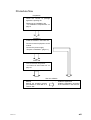
Procedure flow
Preparation
・ Check the content of package
against the packing list
・ Determine the installation site
”1.3 Installation Requirements” on
page 5
Installation
・ Install the module in the basic unit.
・ Connect external equipment to the
module.
・ Connect the power supply
”Chapter 2 Installation” (page 11)
Power ON
・ Turn on the main unit power.
”3.1 Power On and Power off” on
page 21
User the software
・ Backup
Backup the operating system
pre-installed in hard disk to a
reserve disk.
6F8C1111
・ Install the application
Install the application according
to the instruction in the manual.
xiii
Notational convention
Description of symbols
In addition to the Safety Precautions, the following symbols are used to indicate
important notes when using:
Important
Describes items that require special attention in order to properly use the product.
NOTE
Describes items that should be remembered in order to properly use the product.
See
Indicates reference to section in this manual or other manual.
References to section in this manual are enclosed in single quotes (‘ ‘) and references
to section in other manuals are enclosed in double quotes (“ “).
[Remark] Provides supplementary description.
xiv
Computer module C2 User’s Manual
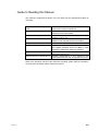
Guide to Reading this Manual
This manual is organized as follows: You may start from the appropriate chapter as
necessary.
Chapter 1 Before Turning on the Summarizes items and caution that you should
Power
know before using this equipment.
Chapter 2 Installation
Describes how to install the equipment to the
base and connect the cables.
Chapter 3 Handling
Describes how turn on/off the power and the
handling of each unit.
Chapter 4 Maintenance
Describes the product life of main components in
addition to the daily maintenance procedure.
Chapter 5 RAS Function
Describes the standard RAS function.
Chapter 6 Hardware Setup
Hardware setup is not necessary for normal use.
This chapter describes how to set BIOS in case
the setting needs to be verified or changed.
Appendix A Q&A
Provides answers to problems such as “The
power does not turn on.”
Appendix B Device Specifications Provides specifications of this equipment and
specifications and pin map of external connectors.
Refer to the operation manual of the respective operating system (OS) for information
concerning the operating system used by this device.
6F8C1111
xv
Functions and Features
The integrated controller model 2000 is a CIE integrated controller integrating
continuous control, high-speed sequence control, maintenance/monitoring, and
information processing control in a single unit.
C2 is a computer module that implements the maintenance/monitoring and information
processing control functions among various functions of the model 2000.
Excellent system performance
l Runs Windows smoothly using a Intel Mobile Pentium III 500MHz CPU with
maximum system memory of 256MB.
Windows2000
l Runs under Windows2000 to enable use of commercial software that supports
GUIenvironment and connectivity with host network.
Consolidation of CIE
l Improves system performance through inter-controller communication using
33MHz clock high-speed bus.
l A variety of sequencer I/O modules can be controlled with the computer module
alone enabling a compact system.
Ease of use
l The hard disk fits inside a 70mm x 135mm x 115mm module and runs Windows
without using an additional module.
l Fully equipped with keyboard, mouse, floppy disk, RS-232C, USB, and Ethernet
connecters, and 2 slots CARDBUS PC card.
Improved reliabillity
l Comes equipped with RAS function which monitors the operating status and
provides detail trouble report. And enables automatic power OFF shutdown
eliminating the trouble of shutting down Windows.
xvi
Computer module C2 User’s Manual
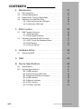
CONTENTS
1 Before Turning on the Power ・・・・・・・・・・・ 1
1.1
1.2
1.3
1.4
1.5
Checking the Content of the Package ・・・・・・・・・・・・・ 1
Name and Function of Each Part・・・・・・・・・・・・・・・・・・ 2
Installation Requirements ・・・・・・・・・・・・・・・・・・・・・・・・ 5
Power Requirements ・・・・・・・・・・・・・・・・・・・・・・・・・・・・ 7
Precautions when using ・・・・・・・・・・・・・・・・・・・・・・・・・ 8
1.5.1 Daily use ・・・・・・・・・・・・・・・・・・・・・・・・・・・・・・・・ 8
1.5.2 When turning Off the Power ・・・・・・・・・・・・・・・・ 8
1.5.3 About the Hard Disk Drive ・・・・・・・・・・・・・・・・・ 8
1.5.4 About the External FDD ・・・・・・・・・・・・・・・・・・・ 9
1.5.5 Daily Cleanup and Storage/Transportation ・・・ 9
1.5.6 Radio Wave/Power Voltage Interference ・・・・・ 9
1.5.7 Repair and Service ・・・・・・・・・・・・・・・・・・・・・・・ 9
1.5.8 Disposal ・・・・・・・・・・・・・・・・・・・・・・・・・・・・・・・・・ 9
2 Installation ・・・・・・・・・・・・・・・・・・・・・・・・・・ 11
2.1
2.2
2.3
2.4
2.5
2.6
3
Handling ・・・・・・・・・・・・・・・・・・・・・・・・・・・ 21
3.1
3.2
3.3
3.4
6F8C1111
Before Getting Started ・・・・・・・・・・・・・・・・・・・・・・・・・・ 11
2.1.1 Procedure ・・・・・・・・・・・・・・・・・・・・・・・・・・・・・・ 11
Installing Bases・・・・・・・・・・・・・・・・・・・・・・・・・・・・・・・・ 12
2.2.1 Precautions when Installing in the Case ・・・・ 12
Module Installation ・・・・・・・・・・・・・・・・・・・・・・・・・・・・・ 13
Grounding ・・・・・・・・・・・・・・・・・・・・・・・・・・・・・・・・・・・・ 14
2.4.1 Grounding Tips ・・・・・・・・・・・・・・・・・・・・・・・・・・ 14
2.4.2 Grounding method ・・・・・・・・・・・・・・・・・・・・・・・ 15
Wiring of the power supply ・・・・・・・・・・・・・・・・・・・・・・ 17
Connector Connection ・・・・・・・・・・・・・・・・・・・・・・・・・・ 20
Power On and Power Off ・・・・・・・・・・・・・・・・・・・・・・・ 21
3.1.1 Turning On the Power ・・・・・・・・・・・・・・・・・・・・ 21
3.1.2 Turning Off the Power ・・・・・・・・・・・・・・・・・・・・ 21
3.1.3 Power Off with Windows ・・・・・・・・・・・・・・・・・・ 22
3.1.4 Power Supply module PS694 with Battery ・・ 22
3.1.5 Power Supply module PS691 with UPS I/F ・・ 24
About the Hard Disk ・・・・・・・・・・・・・・・・・・・・・・・・・・・・ 25
About the External FDD ・・・・・・・・・・・・・・・・・・・・・・・・ 26
3.3.1 Floppy Disk Handling ・・・・・・・・・・・・・・・・・・・・ 26
About the PC Card ・・・・・・・・・・・・・・・・・・・・・・・・・・・・・ 28
3.4.1 Installation ・・・・・・・・・・・・・・・・・・・・・・・・・・・・・・ 29
3.4.2 Removal ・・・・・・・・・・・・・・・・・・・・・・・・・・・・・・・ 30
xvii
CONTENTS
4
Maintenance・・・・・・・・・・・・・・・・・・・・・・・・・・・・・・・・31
4.1
4.2
4.3
4.4
5
5.2
RAS Function Overview ・・・・・・・・・・・・・・・・・・・・・・・・・・・・・・・・・
5.1.1 RAS Hardware ・・・・・・・・・・・・・・・・・・・・・・・・・・・・・・・・・・・
5.1.2 RAS Support Software ・・・・・・・・・・・・・・・・・・・・・・・・・・・・
Hardware Processing RAS Functions ・・・・・・・・・・・・・・・・・・・・・
5.2.1 WDT Circuit and Hardware Reset ・・・・・・・・・・・・・・・・・・
5.2.2 RAS Memory ・・・・・・・・・・・・・・・・・・・・・・・・・・・・・・・・・・・・
5.2.3 Interrupt Signals・・・・・・・・・・・・・・・・・・・・・・・・・・・・・・・・・・
36
36
36
37
37
37
37
Hardware Setup・・・・・・・・・・・・・・・・・・・・・・・・・・・・・39
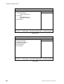
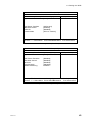
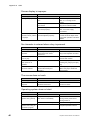
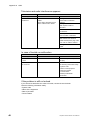
6.1
Setting the BIOS ・・・・・・・・・・・・・・・・・・・・・・・・・・・・・・・・・・・・・・・ 40
A
Q&A ・・・・・・・・・・・・・・・・・・・・・・・・・・・・・・・・・・・・・・45
B
Device Specifications ・・・・・・・・・・・・・・・・・・・・・・・・49
B.1
B.2
xviii
31
32
33
34
34
34
RAS Function・・・・・・・・・・・・・・・・・・・・・・・・・・・・・・・35
5.1
6
Daily Inspection ・・・・・・・・・・・・・・・・・・・・・・・・・・・・・・・・・・・・・・・・
Periodic Maintenance ・・・・・・・・・・・・・・・・・・・・・・・・・・・・・・・・・・・
Replacement Timing of Major Parts ・・・・・・・・・・・・・・・・・・・・・・・
Replacing the Hard Disk Drive・・・・・・・・・・・・・・・・・・・・・・・・・・・・
4.4.1 How to Remove the HDD pack ・・・・・・・・・・・・・・・・・・・・・
4.4.2 Intalling the HDD pack ・・・・・・・・・・・・・・・・・・・・・・・・・・・・
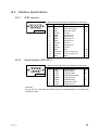
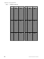
Specifications ・・・・・・・・・・・・・・・・・・・・・・・・・・・・・・・・・・・・・・・・・・
Interface Specifications ・・・・・・・・・・・・・・・・・・・・・・・・・・・・・・・・・・
B.2.1 RGB Interface ・・・・・・・・・・・・・・・・・・・・・・・・・・・・・・・・・・・
B.2.2 Serial Interface (RS-232C) ・・・・・・・・・・・・・・・・・・・・・・・・
B.2.3 Keyboard and Mouse Interface・・・・・・・・・・・・・・・・・・・・・
B.2.4 USB Interface ・・・・・・・・・・・・・・・・・・・・・・・・・・・・・・・・・・・
B.2.5 Ethernet Interface ・・・・・・・・・・・・・・・・・・・・・・・・・・・・・・・・
B.2.6 FDD Interface ・・・・・・・・・・・・・・・・・・・・・・・・・・・・・・・・・・・
B.2.7 PCMCIA card slot ・・・・・・・・・・・・・・・・・・・・・・・・・・・・・・・・
49
51
51
51
52
52
52
53
54
Computer module C2PU37 User’s Manual
Chapter 1 Before Turning
on the Power
1.1 Checking the Content of the Package
Check the content of the package against the packing list included with the product
and make sure everything is included.
6F8C1111
1
Chapter 1 Before Turning on the Power
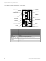
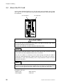
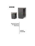
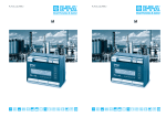
1.2 Name and Function of Each Part
HDD Pack
C2PU37
RGB connector
R UN
PC card slots
RGB
Ethernet
(10/100base-TX)
H DD
4
LEDs indicating
RST
COM por t
10/100BASETX
3
2
HDD
1
HDD Drawer
INZ
COM
RST Sw itch
USB
S W1
KEYBOAR
D
USB connector
1
Mouse
DIP-SW
10/100BASE-TX connector
Keyboard
Connector for the Ethernet 10BASE-T/100BASE-TX connector.
Mouse connector
Connector for the PS/2 mouse.
Keyboard connector
Connector for the PS/2 keyboard.
RGB connector
Connector for the analog RGB display
FDD connector
Connector to connect the 3.5-inch (2HD, 2DD) external floppy disk drive.
RS-232C connector
Connector to connect the RS-232C interface device (such as mouse or
(COM1)
modem).
USB connector
Connector to connect USB compatible device.
LEDs
and
switches
DIP switch
PC card slots
2
HDD fixed board
MOUSE
INZ Sw itch
0
push
button
LEDs indicating the module status and RESET/INZ button.
User settable switches. The setting can be read from user application
program in the C2.
Slot to insert the PC card.
Computer module C2PU37 User’s Manual
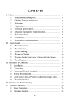
1.2 Name and Function of Each Part
Mounting screw
Station bus connector
1
I/O bus connector
6F8C1111
Mounting screw
A screw to mount the module to the basic unit.
Station bus connector
Station bus connector for the V series model 2000.
I/O bus connector
Connector for the I/O bus.
3
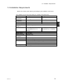
Chapter 1 Before Turning on the Power
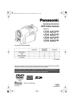
Dedicated LED
General LED
Push button
switch
Dedicated LED
LEDs to indicate the CPU and HDD operating status.
Indicates the operating status of the watchdog timer (WDT).
• When WDT is active
ON: WDT timeout has not occurred
RUN (green)
Blink: WDT timeout has occurred
(Alternating interval is the WDT timeout interval set by the user)
• When WDT is not used
Blink at approximately 1 second interval
General LEDs 1 - 4
HDD (green)
Hard disk drive (HDD) access lamp. Turns ON when the internal hard disk
drive is operating.
General LEDs 1-4
4
(Green/Red: 2 colors x 4)
Switches to perform standalone initialization of the module.
Push button switches
Switches to perform standalone initialization of the module.
RST
Switch to perform hardware reset of the module.
INZ
Switch to shut down Windows and restart.
Computer module C2PU37 User’s Manual
1.3 Installation Requirements
1.3 Installation Requirements
Observe the following when planning and designing the installation environment.
The installation environment must satisfy the conditions described below.
Item
Hard Disk Drive model
Flash Disk Drive model
o
o
Operating ambient
5 – 40 C
0 – 50 C
temperature
o
o
Storage
-10 – 50 C
-25 – 70 C
temperature
Relative humidity
10 to 90%RH, no condensation 5 to 90%RH, no condensation
3
Dust density
10mg/m or less
Corrosion
No corrosive gas is present.
resistance
2
2
Vibration resistance 1.96m/s (0.2G) continuously
9.8m/s (1G) continuously for
for 30 minutes in X, Y, Z
30 minutes in X, Y, Z direction
direction
2
Shock resistance
98m/s (10G) 3 times each X, Y, Z direction
Usable altitude
Up to 2000m
Dielectric strength
1500Vac/1 min.
Ambient
No corrosive gas is present.
atmosphere
Structure
Built-in control panel
Cooling
Natural air cooling
EMC
6 KV
: Static electricity discharge resistance
10 V/m
: Radiation field
2 KV/1 KV/0.25 KV: Fast transient
Grounding resistance 100Ω or less
Grounding
6F8C1111
5
1
Chapter 1 Before Turning on the Power
Follow the precautions described below for the installation of the board housing the
model 2000:
(1) House in a dust proof control board because the module itself is not dust proof.
(2) Avoid installing on top of devices that emit considerable amount of heat (such as
heater, transformer, or large resistor).
(3) Do not install inside the same board with high voltage equipment.
(4) Maintain a distance of at least 200mm from high voltage or power line.
(5) Provide a space of at least 70mm around the base for ventilation.
(6) Keep away from high voltage equipment and power equipment or provide metal
shielding for safety during maintenance and operation.
(7) Be careful not to drop foreign objects such as loose wires inside the module or
unit.
(8) Always mount the base on a vertical panel with the power supply module on the
left. C2 cannot be used in a horizontal position.
(9) Use M4 size screws to mount the unit and fasten securely (recommended torque:
1.47N=15kgf • cm).
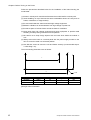
The unit mounting dimensions are as follows:
*1
c
b
a
Model
BU648E
BU643D
BU610
a [mm]
402.5
224.5
155.5
4 - M4
b [mm]
95
95
95
c [mm]
–
203.0
–
Weight [g]
900
850
400
[Note] No hole for BU643D
6
Computer module C2PU37 User’s Manual
1.4 Power Requirements
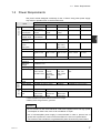
1.4 Power Requirements
Use power module designed exclusively for the V Series. Using other power supply
may result in operation error or device malfunction.
ITEM
Basic function
Rated Voltage
Max. power
consumption
Allowable
voltage range
Rated
frequency
Retentive
power
interruption
Distortion rate
Inrush current
PS691
PS693
100-120VAC
100-240VAC
200-240VAC
160VA(60W)
120VA(50W)
or less
or less
85-132VAC
85-264VAC
170-264VAC
50/60Hz (47-63Hz)
20ms or less
Auxillialy
function
Protective
circuit
Status display
RUN contact
150VA(50W)
or less
85-264VAC
*1
PS632
24VDC
PS652
100/110VDC
50W or less
50W or less
20.4-28.8VDC
85-132VDC
1
DC
20ms / 1s±
30% / 20s±
30% or less
10% or less of rated input voltage
240VAC-25A
220V-30A
240VAC-25A
peak or lower
peak or lower peak or lower
*1
Ground current
Insulation
resistance
Withstand
voltage
Grounding
Output rating
20ms or less
Specification
PS694
100-240VAC
1ms or less
1ms or less
–
6.5A/10ms or
lower of rated
25A or lower
of rated
*1
1.5mA or lower (IEC-950)
10MΩ or higher (between input and each insulation)
–
1500VAC/1 min.
Grounding resistance 100Ω or less
5V-8A,
3.3V-1A total
of 43W or less
5V-7A,
3.3V-1A,
24V-0.8A
total of 35W
or less
Over voltage, currnet protection
5V-6A,
3.3V-1.0A
total of 30W
or less
POWER (5V output, green)
CHARGE*2
Dry A contact (240VAC/24VDC-0.2A max.)
External
Weight
Line terminal
unit
650g or less
600g or less
10 terminals
9 terminals
10 terminals
-M3.5 screw
-M3.5 screw
-M3.5 screw
(detachable)
(fixed)
(detachable)
*1 After instantaneuous power failure of 5 second or longer.
5V-7A, 3.3V-1A total of 35W or
less
POWER (5V output, green)
9 terminals -M3.5 screw (fixed)
*2 Battery initial charge indicator, green/red.
Important
• Do not connect to the same electrical outlet with equipment that has high power
consumption or emits noise, such as air conditioner or copier.
• Use of uninterruptible power supply is recommended in order to prevent loss of
power and to protect the content of the hard disk in the event of a power failure.
The content of the hard disk is not guaranteed if power is lost due to power failure.
6F8C1111
7
Chapter 1 Before turn on the Power
1.5 Precautions when using
1.5.1
Daily use
Observe the following insturctions during daily use of this equipment.
WARNING
• Turn off the power if there is smoke, unusual odor, excessive heat, or damage.
• Do not block the ventilation port.
If the ventilation ports are blocked, heat cannot escape and fire may occur due to
overheating. When there is a need for repair, contact the Toshiba service desk.
• Do not touch the C2 module when the power is on. The heat radiating side covers
o
become extremely hot (ambient temperature+25 C) when power is on. It cools
o
(ambient temperture+10 C) in 10 minutes when the power is turned off.
1.5.2
When turning Off the Power
Important
• After turning off the power, wait at least 5 seconds before turning on the power.
Faulty operation may occur if you do not wait 5 seconds.
• If an application program is running, quit the program to return to the operating
system (OS).
See
• "Description manual of each application program"
1.5.3
About the Hard Disk Drive
Important
• Do not apply shock or vibration to the equipment when the power is on.
The read/write head of the hard disk drive is at a data area even when the HDD
lamp is off.
• Wait at least 30 seconds after turning off the power before moving the equipment.
The read/write head of the hard disk drive retracts automatically when the
equipment power is turned off. However, it takes approximately 30 seconds for the
hard disk to stop rotating.
The shock may damage the data area.
• Always turn off the power before removing/installing the hard disk drive.
Failure to do so can cause malfunction of the drive.
8
Computer module C2PU37 User’s Manual
1.5 Precautions when using
1.5.4
About the External FDD
Important
• Avoid performing the following when the FDD lamp of the external FDD (floppy disk
drive) is ON:
• Pressing the button
• Turning off the main power
• Removing the cable
The floppy disk may be in the middle of reading or writing data and content of the
floppy disk may be damaged.
1
NOTE:
• Always remove the floppy disk from the drive when you are not using the floppy disk
drive.
1.5.5
Daily Cleanup and Storage/Transportation
• Wipe with soft cloth when cleaning. If this is not sufficient, wipe gently with cloth
wetted in water.
• Using benzene, paint thinner, or other chemicals can cause distortion or
discoloration. Also avoid spraying with insecticide.
• Save the box so you can use it when transporting the unit.
• Do not drop of exert excessive shock when transporting. This can cause operation
error or malfunction.
1.5.6
Radio Wave/Power Voltage Interference
If you experience radio or television interference when using this equipment, try the
following:
• Change the direction of the radio or television antenna.
• Change the direction of unit with respect to radio or television.
• Move the unit away from radio or television.
• Use separate electrical outlet from the radio or television.
• Use an outdoor antenna.
• Change the feeder to a coaxial cable.
• Insert a commercially available filter between the electrical outlet and the power plug
of the unit.
1.5.7
Repair and Service
Contact your Toshiba service desk for information concerning maintenance and
service.
6F8C1111
9
Chapter 1 Before turn on the Power
1.5.8
Disposal
Module disposal
The C2 contains parts such as Lithium battery that must be disposed properly
according to local government ordinance.
Do not attempt to dispose the C3 on your own. Please contact your dealer and submit
a request for return and disposal when disposing.
Dispose other 2000 base and modules according to your local government ordinance.
Battery disposal
Dispose the battery in the same manner as ordinary batteries.
Do not disassemble or incinerate the battery because it may explode. Dispose without
disassembling or burning.
Also note that short circuiting the positive and negative end of the Lithium battery may
result in smoke or flame. Do not cut the lead wires and be careful not to short the
positive and negative terminals when disposing.
WARNING
Do not connect the positive and negative terminal of the battery in reverse, or attempt
to charge, disassemble, heat, or short the battery.
It may explode or ignite.
Dispose the battery according to your local government ordinance.
10
Computer module C2PU37 User’s Manual
Chapter2
Installation
2.1 Before Getting Started
2.1.1
Procedure
NOTE:
• Do not touch parts that are not necessary for the work at hand.
• Be careful not to loose the removed screws. Also be careful not to drop them inside
the device.
• If an error or malfunction occurs, contact your Toshiba service desk.
• Use drivers that is appropriate for the screw when assembling or fastening parts.
Improper driver will not fit tightly in the cross hole. Using improper driver can wear
out the cross hole of the screw.
6F8C1111
11
Chapter 2 Installation
2.2 Installing Bases
2.2.1
Precautions when Installing in the Case
Observe the following when installing in the case.
CAUTION
Do not attempt to mount or remove the unit from the case alone (work in two or more).
Be especially careful when mounting in the case because you may lose your balance
and injure yourself.
Important
Use within the following temperature and humidity range.
Temperature
range
Humidity range
o
10 – 90%
o
5 – 95%
Hard Disk Drive model
5 – 40 C
Flash Disk Drive model
0 – 50 C
Avoid sudden change in temperature that may cause condensation.
• Provide a door or removable panel in front and rear of the case in a manner that
facilitates removal of the housed units (main unit and peripheral devices) for
maintenance.
• Provide forced cooling if the temperature inside the case is not within specification.
• Carefully consider the ventilation direction of the main unit, peripheral device, and
case so that the flow of the air is not blocked.
12
Computer m odule C2PU37 User’s Manual
2.3 Module Installation
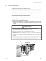
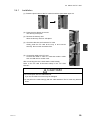
2.3 Module Installation
Install the module according to the following procedure:
(1) Match the guides at top and bottom of the base and insert the module vertically on
the base. Check that the top and bottom lock levers are fasten to the base and
click.
(2) Pass an M3 screw through the hole at the top of the module and secure the base
and the module (recommended torque: 1.47N•m=15kgf•cm).
Remove the module according to following procedure:
(1) Turn off the power supplied to the model 2000. Turn off the external power to the
I/O module.
(2) Detach cables from the module.
(3) Remove the screw at the top of the module.
(4) Push the lock lever at the top of the module, hold the bottom of the module with
the other hand, and pull the entire module vertically from the base to remove the
module.
CAUTION
• Tighten the screws securely so that they do not become loose with vibration.
They can cause injuries if they become loose and fall off.
• Always turn off the power before removing/installing the module.
Removing or installing the module with the power on can cause malfunction or
operation errors.
• The device will not operate normally if installed where there is no station bus
connecter.
• Do not touch the C2 module when the power is on. The heat radiating side covers
o
become extremely hot (ambient temperature+25 C) when power is on. It cools
o
(ambient temperature+10 C) in 10 minutes when the power is turned off.
Station bus Connector
Mounting screw
I/O bus connector
6E8C1111
13
Chapter 2 Installation
2.4 Grounding
The electrical devices should be grounded separately from power system and the two
or more electrical devices should be grounded at a single point. The model 2000 is
designed to resist actual noise and the device is sufficiently capable of withstanding
noise, but grounding is very important in order to assure safe and stable system
operation. Observe the following instructions and provide proper grounding.
When using the Ethernet module, refer to the ‘Ethernet installation and Wiring Guide’
(6F8C0879)
CAUTION
Always ground the model 2000.
Failing to ground the unit can cause electrocution or malfunction.
2.4.1
Grounding Tips
Note the following when grounding:
(1) The model 2000 unit must not be a conductor for grounding current of other
devices.
(Especially, high frequency current can cause trouble.)
(2) The grounding potential of the model 2000 base and expansion unit must be equal.
(Ground at single point.)
(3) Do not connect to ground of motorized system (require high frequency separation)
(4) Do not connect to unstable ground (parts with unstable impedance such as
screwed on painted parts or parts affected by vibration)
14
Computer m odule C2PU37 User’s Manual
2.4 Grounding
2.4.2
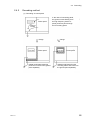
Grounding method
(1) Grounding of control panel
Power panel
Ground
current
change
Power panel
Isolate model 2000 mounting
panel and connect to the ground
point separately
6E8C1111
In the case of connecting panel,
the ground current flowing from
the high frequency device or
power panel may flow through
the PC housing panel.
change
Power panel
Isolate model 2000 from the
mounting frame and connect to
the ground point separately.
15
Chapter 2 Installation
(2) Grounding connection between base
PS
Basic unit
FG
PS
Expansion unit
PS
Expansion unit
Board internal ground terminal
Dedicated ground
• Connect the FG terminal of the power supply module to the unit mounting screw,
2
and to the ground bar in the panel by 2mm or larger wire in shortest possible
distance.
• Use a dedicated ground for the control circuit, and keep the ground cable away
from that for high-power systems.
• 100Ω or less to earth is recommended.
(3) Line Filter ground (LG) terminal
The LG terminal is a neutral point of the primary power supply line filter. It can
suppress the effect caused by the noise from power supply line, by grounding the
LG terminal.
Therefore, normally, ground the LG terminal together with the FG terminal.
However, depending on the power system, leakage current to the ground from the
LG may cause problems. In this case, install an isolated transformer in the power
line, or open the LG terminal. If the unit is installed in isolation, open the LG
terminal.
Do not connect the LG and FG terminals without grounding them.
(4) Frame ground (FG) terminal
The FG terminal is a protective ground point of the model 2000. The FG terminal
voltage is equalized to that of the base. For safety, ground them at single-point in
order to minimize the risk of electrical shock.
16
Computer m odule C2PU37 User’s Manual
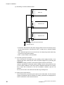
2.5 Wiring of the power supply
2.5 Wiring of the power supply
Wire the external power supply to model 2000 power supply module in the following
manner.
When using expansion units, arrange for power to be supplied simultaneously to the
basic unit and the expansion units (or to the expansion units before the basic unit).
(1) Power conditions
Rated voltage
: 85 to 264VAC, 50/60Hz (PS694)
Power consumption
: 150VA or less (PS694)
Retentive power interruption
: 20ms or less
(2) Install an electrostatic shielded transformer or a noise filter if the power contains
noise. See figurer at the bottom.
2
(3) Use twisted-pair cables (1.25mm ) as the power supply cable. Keep the cable as
far as possible from I/O cables.
(4) If the expansion unit with a power supply module is used, the power of the basic
and expansion units should be supplied from the same source. Apply power at the
same time or in the order of the expansion unit then the basic unit.
(5) If a CVCF or UPS supplies power to model 2000, observe waveforms of the power
supply; the peak voltage must be more than 130V for the 100VAC range or 260V
for the 200VAC range.
Basic unit
Noise filter
Shielded
transformer
(
(
Power
100/240VAC
Expansion unit
6E8C1111
17
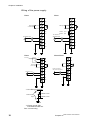
Chapter 2 Installation
Wiring of the power supply
PS694
PS691
NC
NC
NC
NC
RUN signal
contact output
RUN signal
contact output
NC
100VAC:short
200VAC:open
NC
100-240VAC input
L
100-120VAC or
200-240VAC input
L
∼
∼
*1
N
N
LG
LG
FG
FG
*1
*2
PS693
*2
PS632/PS653
24V output
DC24V
0V
+
−
+
NC
−
NC
RUN signal
contact output
RUN signal
ontact output
NC
NC
24VDC input (PS632)
100/110VDC input (PS653)
L
100-240VAC input
L
∼
N
N
LG
FG
*1
*1
*2
*2
*1 Line filter ground (LG)
5000PF or less
Power supply
input
5000PF or less
LG
*2 Frame ground (FG)
Connected to base unit.
See ‘2.4 Grounding’
18
Computer m odule C2PU37 User’s Manual
2.5 Wiring of the power supply
CAUTION
1.
Always turn off the power before wiring the cables.
Working with the power on can cause electrocution.
2.
Use covered crimp terminals or cover the module wire with tape so that there
is no exposed conducting parts.
Fasten the terminal covers securely to the terminals when wiring is finished.
Exposed parts can cause electrocution.
3.
Always ground the model 2000.
Failing to ground the unit can cause electrocution or malfunction.
4.
Connect to rated power supply.
Connecting to wrong power supply can cause explosion or fire.
5.
Wiring must be performed by an experienced person.
Wiring error can result in fire, malfunction, or electrocution.
6.
Do not connect any cables to the NC terminals.
NOTE:
Terminal screw size is M3.5. Use crimp terminal with width of 7mm or less for M3.5
screw.
6E8C1111
19
Chapter 2 Installation
2.6 Connector Connection
Connect each connector to the peripheral device as described below.
CAUTION
• Turn off the power of the main unit and peripheral device when connecting peripheral
devices.
Connecting with the power on may cause injury or burn.
• Be sure to hold the connector when attaching/removing signal cables.
Otherwise, the cable may be damaged causing fire or electrocution.
Important
• Check the shape of the connector and insert the cable properly into the main unit.
The pins may break or bend if unnecessary force is applied.
• If the cable connector is equipped with fastening screws, tighten them so that the
cable does not come loose.
(1) Check that the switch of the power module is in the OFF position.
(2) Connect the cable of each peripheral device to the main unit connector.
After connecting, tighten two screws and fasten the connector to the module.
Match the connectors properly when connecting and connect firmly.
20
Computer m odule C2PU37 User’s Manual
Chapter3
Handling
3.1 Power On and Power Off
If you are using peripheral devices, connect them before turning on the main unit
power.
Important
• Wait at least 5 seconds when turning on the power after turning it off.
If the power is turned back on too quickly, the rush current prevention circuit may
not function properly and a sudden flow of current (approximately 100A) may cause
the power supply fuse to blow out.
3.1.1
Turning On the Power
Configure the external circuit to power on in the following sequence:
(1) Turn on the AC power to the power supply module.
(2) Turn on the power of the peripheral devices (CD-ROM drive connected through
PC card, etc.) connected to C2.
(3) Turn on the model 2000 main unit.
(4) Turn on the I/O module and external load power.
3.1.2
Turning Off the Power
Turn off the power in the reverse order of the power on procedure.
NOTE:
If an application program is running, quit the program to return to the operating system
(OS).
Then shut down the operating system and get ready to power off.
If PS694 or PS691 is used for a power supply module, a shutdown will be performed
automatically and a module power supply will be shut off.
Please refer to the following page for details.
6F8C1111
21
Chapter 3 Handling
3.1.3
Power Off with Windows
If a power supply is turned off without shutdown of Windows, the data in a hard disk is
destroyed and it may be unable to reboot.
Model 2000 is supporting the automatic shutdown of Windows, and the power supply
off-sequence. If the power supply module of exclusive use is used, the shutdown of
Windows can be performed without carrying out operation of a mouse and a keyboard.
Important
• In order to use an automatic shutdown function, the RAS support software installed
in C2 as standard is required.
3.1.4
Power Supply module PS694 with Battery
C2
Power Supply Module PS694
Windows
Detect AC Failure
Shutdown
Sequence
Shutdown
Request
RAS driver
Main circuit
AC100/240V
Battery
Control
Shutdown
Request
Power control signal
Main power for controller
l
22
Operation during power off
(1) An AC input power failure exceeding the preset allowable limit is detected as a
power failure. (Normal operation continues if power fails shorter than that.)
(2) Shutdown is requested to the C2 and the C2 starts shutdown processing.
(3) When the C2 finishes shutdown processing, the power module PS694 cuts
power off by stopping power supply from the battery.
Computer module C2PU37 User’s Manual
Important
• If the running application cannot be terminated normally for some reason or other,
Windows is forcibly terminated subject to the completion waiting time set with the
RAS driver.
In this case, the file data of application or Windows may be destroyed.
Fully confirm application operation in advance that it is free of problems.
Important
• If an input power supply is turned off during Windows starting, power supply OFF
may be carried out without carrying out shutdown processing.
Important
• When it mounts two or more sets of C2 in one base unit, after all C2 carries out the
completion of a shutdown, power supply OFF is carried out.
l Operation after power recovery
If AC power is restored during the shutdown processing, power is automatically turned
back on after the operation described in step (3).
l Hold time and charge time of a built-in battery
The battery's hold time is 4 minutes maximum (when the battery is fully charged and
operates at the rated output level). A recharge of about 2 hours is necessary for the
battery to make up for the loss of its capacity by a single Windows shutdown after AC
input power is back on.
Important
• When battery capacity runs short during battery operation, a power supply is turned
off compulsorily.
In this case, the file data of application or Windows may be destroyed.
Do not repeat OFF of an input power supply.
Important
• PS694 is not a thing supposing use in the inferior input power supply state.
Battery operation is performed, while the input power supply turns off, even if it is
less than the set-up time at the time of retentive power interruption.
When there is extremely much generating frequency of a power interruption, the
charge capacity of a battery runs short and power supply OFF may be carried out
before the completion of a shutdown at the time of input power supply OFF.
6F8C1111
23
Chapter 3 Handling
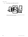
3.1.5
Power Supply module PS691 with UPS I/F
C2
Power Supply Module
PS691
W indows
UPS
Conversion
circuit
Shutdown
Request
RAS driver
AC100/240V
Main circuit
Shutdown
Request
Power control signal
Main power for controller
UPS turns off secondary side power supplies in timer setting of UPS. A timer should
set up sufficient time for shutdown of Windows.
24
Computer module C2PU37 User’s Manual
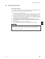
3.2 About the Hard Disk
3.2 About the Hard Disk
Hard Disk Handling
The C2 hard disk drive is likely to be misused because it can be replaced or carried
easily. Observe the following precautions and treat it with care:
l
l
l
l
l
l
Do not drop it or exert strong shock.
The magnetic surface of the hard disk may be damaged making it unusable.
Scars on the magnetic surface cannot be repaired. Handle it with extreme care.
Carrying it without installing it on C2 can make it more susceptible to shock and
the data may be lost or become unreadable. Place it in a box and handle with
care. Be especially careful when transporting.
Place the removed hard disk drive in an anti-static bag and store it in a box.
The hard disk pack may be replaced approximately 500 times. This is the life of
the connector.
Avoid spilling coffee, other fluids, or metal particles.
Do not disassemble. Failure to do so can cause malfunction of the drive.
Important
• Toshiba will not be responsible for the content of the hard disk regardless of the
cause of failure or error. Please backup your data to guard against accidents.
• Use only C2 custom hard disks.
6F8C1111
25
3
Chapter 3 Handling
3.3 About the External FDD
An external floppy disk drive is necessary if you must install OS or application
programs from floppy disks or save data to floppy disks.
In general, a floppy disk drive has an access lamp in front as shown at right. This lamp
flashes when the drive is being accessed.
FDD lamp
CAUTION
• Turn off the AC power of the main unit when removing/inserting the FDD cable.
Removing or inserting the cable with the main unit power on can cause burn or
electrocution.
• Do not press the eject button or turn off the power when the FDD lamp of the
external floppy disk drive is on.
3.3.1
Floppy Disk Handling
Important
• Do not open the shutter and touch the magnetic surface.
• Avoid extreme environment such as direct sunlight, strong magnetic field, or high
temperature.
• Do not put heavy object on top.
• Do not paste labels on top of each other.
26
Computer module C2PU37 User’s Manual
3.3 About the External FDD
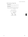
[Write Protecting a Floppy Disk]
To prohibit write
Slide the write protect tab to the outside as shown in (1).
To enable write
Slide the write protect tab to the inside as shown in (2).
In either case, slide the write protect tab until it clicks
Write protect tab
Shutter
Front
Back
3
Write disabled state Write enabled state
6F8C1111
27
Chapter 3 Handling
3.4 About the PC Card
Two PC Cards Standard TYPE I/II (3.3V, 5V) PC cards can be inserted in the PC card
slot of the C2. Or, one TYPE III PC card can be inserted when the left and right slots
are combined.
PC card slot 0
PC card slot 1
C2PU37
RUN
RGB
HDD
4
2
1
HDD
RST
1 0 / 1 0 0 B A S E- TX
3
INZ
COM
SW1
1
MOUSE
USB
0
KEYBOARD
CAUTION
• Do not touch the PC card that is being used or just after it has been used. It may
become extremely hot and cause burns.
Persons with weak skin condition should be especially careful.
Important
• When using a card that requires a cable, the cable may be short. Check the location
of the main unit and the peripheral device to be connected.
• The size of a cable or a connector of a PC card are large, and may be unable to
insert two cards simultaneously. Please check the size of the card to be used etc.
beforehand. If a PC card is inserted by force, it may become the cause of incorrect
operation and failure.
Memo
• Some commercially available PC cards may emit considerable amount of heat. The
function of such card may become unstable when it is used for an extended period.
Also, if it is used together with other cards, the heat may affect the other card.
Examples of PC card
• Modem card
• SCSI adapter
28
• Flash memory
• LAN card
Computer module C2PU37 User’s Manual
3.4 About the PC card
3.4.1
Installation
(1) Press the eject button of the PC card slot until the eject button pops out.
(2) Press the eject button once more.
The dummy card ejects.
(3) Remove the dummy card.
Store the dummy card in a safe place.
(4) Check the direction and insert the PC card.
Gently press the PC card all the way in and connect
securely. Do not exert excessive force.
3
(5) Connecting cable to the PC card.
Connect the cable in case of a card that needs a cable
such as LAN card or modem card.
After connecting the card, check that the card is ready.
Refer to the PC card environment setup in the "PC Card
Manual."
CAUTION
• Do not transport with the cable attached.
If you do, the cable connector may be damaged.
• Do not pull on the cable strongly with the cable attached. The PC card may become
loose.
6F8C1111
29
Chapter 3 Handling
3.4.2
Removal
(1) Press the eject button of the PC card slot until the eject button pops out.
(2) Press the eject button once more.
The card ejects.
(3) Hold the card firmly and pull.
(4) Insert a dummy card.
30
Computer module C2PU37 User’s Manual
Chapter 4 Maintenance
4.1 Daily Inspection
The following items should be inspected daily in order to maintain normal system
operation and prevent unnecessary trouble from occurring.
Item
Check the LED in
front of the power
module.
Check the LED at the
front of the C2
module.
Check the LED of the
input module.
(Digital input)
Inspection Description
POWER (green): On when 5V
power supply is normal
Check the LED of the
output module.
(Digital output)
When output is ON,
corresponding LED is ON and
corresponding external load is
active.
RUN (green): ON when
program is running normally.
When external input signal is
ON, the corresponding LED is
ON.
LEDs indicating blown fuse
and external power failure
(FL, FH, or F) are OFF.
Action
Inspect the power supply
related items under "Periodic
Inspection" below.
See below
• Check that the input voltage
is within specification.
• Check that the input
terminal is secure.
• Check that the module is
secured.
• Check that the external load
voltage is within
specification.
• Check the internal fuse.
• Check that the output
terminal is secure.
• Check that the module is
secured.
Action
• When the C3 module LED status is abnormal
The application program may be at fault if the error is not corrected after performing
the following. Check the application program once more.
(1) Restarting the C2 module.
(2) Replacing the C2 module.
6F8C1111
31
Chapter 4 Maintenance
4.2
Periodic Maintenance
Check the following items periodically (once every six month is recommended). Also
check these items when the surrounding condition or environment is changed.
Item
Power supply related
Installation
I/O module related
Environment
Battery related
Inspection Description
Power supply voltage
(measure at the power supply
terminal of the module)
Check for loose power supply
terminal screws
Check for damaged cables
Check that the base unit is
securely in place
Check that each module is
securely in place
Check for loose connector in
front of the module and
damaged cables
Measure voltage of each I/O
terminal
Check the input status LED
Check the output status LED
Check that the I/O terminal is
secure
Check that the terminal
screws are secure and not
touching each other
Check for damaged cables
Check the temperature,
humidity, vibration, and dust
C2 built-in Litium battery
PS694 battery
Other battery
Check that the battery
connector is connected
securely
Action
AC85 - 132VAC/170 264VAC
Must be secure
Must not be damaged
Must not be loose
Must not be loose
Must not be loose or
damaged
Must be within specification
Must turn ON normally
Must turn ON normally
Must not be loose
Must not be loose or touching
each other
Must not be damaged
Must be within installation
environment specification
Should be replaced after 10
years by C2 overhaul
Should be replaced
after 3 years (Ni-Cd battery)
after 1 year (Ni-MH battery)
Should be replaced after two
years
Must be secure
WARNING
• Do not attempt to disassemble, modify, or repair.
This can cause electrocution, fire, or injury.
Contact the Toshiba service desk for repair.
32
Computer module C2PU37 User’s Manual
4.3 Replacement Timing of Major Parts
CAUTION
• Take extreme precaution when measuring the power supply voltage at the power
supply terminal of the module during inspection.
There is a danger of electrocution.
• Do not touch the C2 module when the power is on. The heat radiating side covers
o
become extremely hot (ambient temperature+20 C) when power is on. It cools
o
(ambient temperature+10 C) in 10 minutes when the power is turned off.
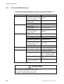
4.3
Replacement Timing of Major Parts
Listed below are the product life of major components. Periodically replace parts using
this table as reference. Contact your Toshiba service desk for information concerning
the price and ordering method of replacement parts.
Product life of major components
Location of
Parts
Description
Product Life
wear
Hard disk
Mechanism Wear
5 years or 20,000
drive
cumulative power on hours
which ever comes first.
Battery
Capacity
Depletion
500 power interruptions or
(PS694 built-in
3 years, whichever come
first. (Ambient temperature
Ni-Cd)
o
35 C)
Battery
Capacity
Depletion
450 power interruptions or
(PS694M
1 year, whichever come
built-in Ni-MH)
first. (Ambient temperature
o
35 C)
Battery
Capacity
Depletion
10 years (Ambient
o
(C2 built-in)
temperature 35 C)
PC Card slot Functional Wear
10000 insertions/removals
parts
External FDD Mechanism Wear
5 years or 15,000
cumulative power on hours
which ever comes first.
Parts
Keyboard
Mouse
CRT
Product life of major components
Location of
Description
Product Life
wear
Mechanism Wear
100,000 strokes
Mechanism Wear
100,000 clicks
Displays
10,000 cumulative power
on hours
Replacement
Action
Interval
2 years
Replace
—
Replace
—
Replace
10 years
Parts replacement
by overhaul
Parts replacement
by overhaul
Replace
—
2 years
Replacement
Action
Interval
—
Replace
—
Replace
—
Replace
In addition to the main unit, disk drives such as the CD-ROM, and MO drive also have
a product life. Check the product life of the peripheral devices being used and replace
them before their product life expires.
6F8C1111
33
Chapter 4 Maintenance
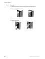
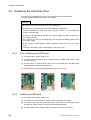
4.4 Replacing the Hard Disk Drive
The main unit is equipped with one 2.5 inch hard disk drive in the HDD pack.
The HDD pack replacement procedure is as follows:
Important
• Be careful not to exert excessive shock to the HDD pack.
• Always turn off the power before removing/installing the HDD pack.
Removing/installing the HDD pack with the power turned on can damage the
content of the hard disk.
• Exchange of an HDD pack should shut off a power supply, and after 30 seconds or
more pass, perform it.
The contents of a disk may be destroyed if it exchanges immediately after turning
off a power supply.
• Be sure to pull out HDD Drawer metallic ornaments using tools, such as a minus
driver.
If a finger pulls directly, there is a possibility of removing a nail.
4.4.1
How to Remove the HDD pack
(1) It checks that the power supply is off.
(2) The screw of the HDD fixed board is loosened and the HDD fixed board is made
to slide to the left.
(3) A minus driver is united with the slot in front of an HDD pack, and HDD pack
drawer metallic ornaments are pulled out.
(4) An HDD pack is removed pulling HDD pack drawer to the front.
4.4.2
Intalling the HDD pack
(1) It checks that the power supply is off.
(2) The direction of up-and-down is checked and an HDD pack is inserted.
(3) If it enters to the back, the upper part and the lower part of an HDD pack will be
pushed with a finger, and a connector will be combined certainly.
(4) An HDD fixed board is made to slide to the right, and it fixes with a screw.
34
Computer module C2PU37 User’s Manual
Chapter 5 RAS Function
RAS function (Reliability, Availability, Serviceability) represents the function which
increases the operating performance of the C2. C2 is equipped with RAS hardware
and RAS support software to facilitate the use of RAS functions.
Persons in charge of design, operation, or maintenance of the C2 should have
sufficient knowledge of these function in order to be ready in case of trouble.
This chapter provides an overview of the RAS hardware and software and describes
the hardware operation.
6F8C1111
35
Chapter 5 RAS Function
5.1 RAS Function Overview
The RAS hardware and software provide the following functions.
5.1.1
RAS Hardware
Internal diagnosis
Power ON/OFF function
Reset function
Interrupt output function
RAS memory function
5.1.2
Circuit that detects internal abnormal conditions.
• WDT monitoring
• DRAM ECC error detection
• CPU temperature/CPU peripheral temperature rise detection
• Power voltage drop detection
• C2 built-in Battery failure detection
OFF detection of an input power supply, and control of a power
supply.
The function reset at the time of abnormalities
• Compulsive initialization switch (INZ switch)
• Compulsive hardware reset switch (RST switch)
Non-maskable interrupts (NMI) and maskable interrupts (MI) are
available.
NMI: Power off, WDT, initialize switch control
MI: CPU peripheral temperature rise, interval timer
(MI can be enabled/disabled by software)
Equipped with battery backed RAS memory (64K bytes) to save
information while running.
• Saving of error information
• Saving of user information
RAS Support Software
This section provides a general description of the RAS support software. Refer to the
"Computer module C2/C3 Windows User’s Manual (6F8C0894)" for more information
concerning RAS function software processing.
The Windows version C2 is shipped with the RAS support software installed.
The RAS support software consists of RAS hardware drivers and RAS software libraries and
there are two ways to use it.
From the RAS windows
From the user program
36
It can be used simply by registering the RAS window parameter
during installation.
Used by creating a user application program using RAS
commands in VC (Visual C++) or VB (Visual Basic) for the
specific purpose.
Sufficient knowledge of the hardware functions is necessary to
create the program.
Computer module C2PU37 User’s Manual
5.2 Hardware Processing RAS Functions
5.2 Hardware Processing RAS Functions
5.2.1
WDT Circuit and Hardware Reset
The WDT circuit issues an NMI to the main unit when the WDT counter is not reset within a
certain interval (WDT monitoring interval). The WDT monitoring interval can be set up to
500ms x 255 (approximately 2 minutes) in 500ms units.
If an NMI is not accepted within 500ms after a WDT timeout NMI is issued, the system is
reset by the hardware reset function.
WDT reset
500ms*N
500ms*N
500ms
(recover because reset
within 500ms)
NMI
request
NMI issued
Force reset
output
Force reset because NMI (WDT) reset is not performed by CPU
<WDT and forced reset time chart>
Important
• Do not enable the suspend function when using the WDT function. This may cause a
mal-function.
The suspend function is a power saving method and cannot be used together with
the WDT function.
5.2.2
RAS Memory
RAS memory is a 64K-byte battery backed non-volatile memory and is used to store NMI
events and RAS information. It is also used by the RAS support software to save shutdown
information.
RAS memory is designed to be accessed using the I/O space and does not use any
memory space.
RAS memory is backed up by the backup battery (Lithium battery) installed inside the main
unit.
5.2.3
Interrupt Signals
Interrupts detected by RAS board and sent to CPU are classified into NMI events and MI
events.
• Examples of NMI events are: WDT timeout, events requiring immediate action such as
power failure, system shutdown, and remote input for power control.
• An example of MI event is fan stop.
6F8C1111
37
5
Chapter 5 RAS Function
[NMI events]
NMI events are the following:
• power off
• WDT timeout
• Pressing of the INZ switch
An NMI signal is sent to the main unit when any one of these events occur. An NMI event is
latched inside the RAS board and held until it is processed by the RAS support software.
A forced reset (hardware reset) is issued and the system is reset unless an NMI processing
RAS support software is executed within 500ms after the occurrence of these NMI events.
(NMI process monitoring timer)
If a RAS support software is installed, monitor timer reset for the NMI is performed by the
software so that the NMI need not be processed by user application.
[MI events]
MI events are the following:
• Rise in temperature (main unit internal temperature)
• Interval timer
• Fan stop
An interrupt occurs when the temperature becomes abnormal, fan stops, or when the
interval timer expires.
38
Computer module C2PU37 User’s Manual
Chapter6
Hardware Setup
The C3 hardware can be set from the BIOS screen. Normally, the setting need not be
changed. Do not change the setting unnecessarily. If it is set incorrectly, the hardware
may be damaged.
If you inadvertently changed it incorrectly, you must change it back to the correct
setting.
This section describes how to set the BIOS in such case.
6F8C1111
39
Chapter 6 Hardware Setup
6.1 Setting the BIOS
The method of displaying the BIOS screen and the displayed content (default value) are
shown below. Check the content before using or when there is an abnormal condition.
Important
• Do not enable the suspend function when using the WDT function. This may cause a
mal-function.
The suspend function is a power saving method and cannot be used together with
the WDT function.
(1) Turn on the main unit power.
The following BIOS startup screen appears.
PhoenixBIOS X.X Release X.X.X
Copyright 1985-2002 Phoenix Technologies Ltd.
All Rights Reserved
CPU = Pentium(R) III prosessor 500MHz
636K System RAM Passed
XXXM Extended RAM Passed
256K Cache SRAM Passed
System BIOS shadowed
Video BIOS Shadowed
UMB upper limit segment address:F0DF
Fixed Disk 0:(DISK Maker/Type)
Press <F2> to enter SETUP
BIOS startup screen
40
Computer module C2PU37 User’s Manual
6.1 Setting the BIOS
(2) Press F2 when the BIOS startup screen appears.
The BIOS main menu appears.
Main Advanced
System Time
System Date
Phoenix BIOS Setup Utility
Boot Exit
[ XX:XX:XX ]
[ XX/XX/2000]
Legacy Diskette A:
[Disabled]
▼ Primary Master
▼ Primary Slave
▼ Secondary Master
[DISKのメーカ型式]
[None]
[None]
System Memory:
Extended Memory:
Memory Cache:
640 KB
XXXXXX KB
[Enabled]
Item Specific Help
F1 Help ↑↓ Select Item -/+ Change Values
F9 Setup Defaults
Esc Exit ←→ Select Menu Enter Select ▼Sub-Menu F10 Save and Exit
BIOS main menu screen
(3) Select each item from this main menu and check the content.
The content of each screen is as follows.
Phoenix BIOS Setup Utility
Main Advanced Boot Exit
Installed O/S:
[Other]
Reset Configuration Data: [No]
PS/2 Mouse
[Auto Detect]
Item Specific Help
▼ I/O Device Configuration
Large Disk Access Mode:
Local Bus IDE adapter:
[Dos]
[Primary]
▼ Advanced chipset Control
Legacy USB Support:
PCI IRQ line1:
[Enabled]
[11]
F1 Help ↑↓ Select Item -/+ Change Values
F9 Setup Defaults
Esc Exit ←→ Select Menu Enter Select ▼Sub-Menu F10 Save and Exit
Advanced screen
6F8C1111
41
Chapter 6 Hardware Setup
Main
Advanced
Phoenix BIOS Setup Utility
Boot
Exit
Item Specific Help
+ Removable Devices
Legacy floppy Drives
+ Hard Drive
(DISK Maker/Type)
bootable Add-in cards
CD-ROM Drive
F1 Help ↑↓ Select Item -/+ Change Values
F9 Setup Defaults
Esc Exit ←→ Select Menu Enter Select ▼Sub-Menu F10 Save and Exit
BOOT screen
Main
Advanced
Phoenix BIOS Setup Utility
Boot
Exit
Item Specific Help
Exit Saving Changes
Exit Discarding Changes
Load Setup Defaults
Discard Changes
Save Changes
F1 Help ↑↓ Select Item -/+ Change Values
F9 Setup Defaults
Esc Exit ←→ Select Menu Enter Select ▼Sub-Menu F10 Save and Exit
Exit screen
42
Computer module C2PU37 User’s Manual
6.1 Setting the BIOS
Phoenix BIOS Setup Utility
Main
Type:
Primary Master [ DISK Maker/Type]
[Auto]
Multi-Sector Transfers
LBA Mode Control
32 Bit I/O
Transfer Mode
Item Specific Help
[XX Sectors]
[Enabled]
[Disabled]
[FPIO X/DMA X ]
F1 Help ↑↓ Select Item -/+ Change Values
F9 Setup Defaults
Esc Exit ←→ Select Menu Enter Select▼Sub-Menu F10 Save and Exit
Primary Master (Sub-Menu) screen
Phoenix BIOS Setup Utility
Main
Primary Slave/Secondary Master [None]
[Auto]
Type:
Multi-Sector Transfers:
LBA Mode Control:
32 Bit I/O
Transfer Mode:
SMART Monitoring:
Item Specific Help
[Disabled]
[Disabled]
[Disabled]
[Standard]
Disabled
F1 Help ↑↓ Select Item -/+ Change Values
Esc Exit ←→ Select Menu Enter Select▼Sub-Menu
F9 Setup Defaults
F10 Save and Exit
Primary Slave/Secondary Master (Sub-Menu) screen
6F8C1111
43
Chapter 6 Hardware Setup
Phoenix BIOS Setup Utility
Advanced
I/O Device Configuration
Serial port A
[Auto]
Serial port B
[Disabled]
Parallel port
[Disabled]
Floppy disk controller
[Enabled]
Base I/O address
[Primary]
Item Specific Help
F1 Help ↑↓ Select Item -/+ Change Values
F9 Setup Defaults
Esc Exit ←→ Select Menu Enter Select▼Sub-Menu F10 Save and Exit
I/O Device Configuration screen
Phoenix BIOS Setup Utility
Advanced
Advanced Chipset Control
[4.5]
8-bit I/O Recovery:
[4.5]
16bit I/O Recovery:
Disabled
Enable memory gap:
[ECC]
ECC Config:
[Multiple bit]:
SERR signal condition:
Item Specific Help
F1 Help ↑↓ Select Item -/+ Change Values
Esc Exit ←→ Select Menu Enter Select▼Sub-Menu
F9 Setup Defaults
F10 Save and Exit
Advanced Chipset Control screen
(4) If the displayed content is different, correct the setting and perform SAVE & EXIT
(F10) to save the content.
44
Computer module C2PU37 User’s Manual
Appendix A
Q&A
Sometimes, the device does not function as you expected or you may not know what
to do next. Read this section before you suspect that the device is faulty.
If an error message appears while using an operating system command, refer to the
operating system manual.
For information concerning the use of each application program, refer to the operation
manual of the respective application program.
Power does not turn on.
Q
Symptom
The main unit power
does not turn on.
A
Check
Is the power cable connected to
the electrical outlet?
Action
Turn off the AC power switch of
the power module and plug into
the electrical outlet.
See "3.1.1 Turning On the
Power"
Plug into proper electrical outlet.
Is power supplied to the electrical
outlet?
An error message appears.
Q
Symptom
An error message
appears during startup.
A
Check
Did you turn the power off and
then back on immediately?
Is the BIOS set correctly?
An error message
appears when using an
application program.
6F8C1111
Action
Wait at least 5 seconds after
turning off the power before
turning it back on.
Refer to "6.1 Setting the BIOS"
and check.
Refer to your application
program's operation manual.
45
Appendix A Q&A
Screen display is improper.
Q
Symptom
Nothing is displayed.
A
Check
Is the main unit and CRT power
on?
Action
Turn on the power.
See "3.1.1 Turning On the
Power"
Turn off the power once and
plug into an electrical outlet.
Connect the cable securely.
See "2.5 Power Supply
Connection"
Turn the brightness and
contrast knobs to adjust. Refer
to the CRT operation manual for
details.
Is the CRT power cable
connected?
Is the CRT signal cable
connected properly?
Screen display is
distorted, size or position
is improper.
Are the CRT brightness and
contrast adjusted properly?
No character is entered when a key is pressed.
Q
Symptom
Unable to enter from the
keyboard.
There is no response
from any key.
There is no response
when power on is
repeated.
The desired character
cannot be entered.
A
Check
Is the keyboard cable plug
connected to the mouse
connector?
Action
Connect the keyboard cable
plug to the keyboard connector.
Turn the power off and then
back on after a while.
Press the {Del} key while
pressing the [Ctrl] key and [Alt]
key.
Use the [Caps Lock] key and
[Num Lock] key to obtain the
desired state.
Are the CapsLock, NumLock,
and ScrollLock lamps lit
properly?
The mouse does not work
Q
Symptom
The mouse does not
Respond
A
Check
Is the mouse connected to the
keyboard connector?
Action
Connect the mouse to the
mouse connector.
Operating system does not start.
Q
Symptom
An error message
appears during startup.
A
Check
Did you turn the power off and
then back on immediately
Is the BIOS set correctly?
An error message
appears when using an
application program.
46
Action
? Wait at least 5 seconds after
turning off the power before
turning it back on.
Check "6.1 Setting the BIOS"
Refer to your application
program's operation manual.
Computer module C2PU37 User’s Manual
Application program cannot be used
Q
Symptom
Application program
does not work as
expected.
Application program
does not run.
A
Check
Is the system configuration set
correctly?
Action
Refer the operation manual of
the application program and
change the system
configuration if instructed.
The application program must
support the current operating
system. Purchase an
appropriate application
program.
Does the application program
support the current operating
system?
The floppy disk drive cannot be used
Q
Symptom
FDD lamp does not go
off.
A
Check
Action
Wait until the lamp goes off
when processing large data. If
the lamp still does not go off,
quit the task (turn off the power)
and contact the service desk.
The floppy disk cannot be used
Q
Symptom
An error message "Write
protected" appears.
An error message
"Unable to create file"
appears.
An error message "Disk
full" appears.
6F8C1111
A
Check
Action
Is the floppy disk write protected? Take out the floppy disk and
enable it for write.
Is the sub directory created? e.
Create a sub directory and then
create the fil
Is there sufficient disk space?
Delete unnecessary file and
retry.
Use a different floppy disk.
47
Appendix A Q&A
Television and radio interference appears
Q
Symptom
There is TV and radio
interference.
A
Check
Is the device near the TV or
radio?
Is the device plugged into the
same outlet as TV or radio?
Action
Change the direction of the
indoor radio or television
antenna.
Change the direction of the unit
with respect to radio or
television.
Move the unit away from radio
or television.
Use separate electrical outlet
from the radio or television.
Insert a commercially available
filter between the electrical
outlet and the power plug of the
unit. Use an outdoor antenna.
Change the feeder to a coaxial
cable.
In case of trouble or malfunction
Q
Symptom
There is abnormal smell
or heat.
Trouble or malfunction
has occurred.
A
Check
Action
Turn off the power and pull out
the plug.
Contact the service desk. Have
the following information ready:
• System code
• Name of the equipment
• Date of purchase
• Current status
Please provide detail
information.
If the problem is still not solved
If you still cannot determine the cause of trouble, contact the service desk.
Have the following information ready:
• System code
• Name of the equipment
• Date of purchase
• Current status
48
Computer module C2PU37 User’s Manual
Appendix B
B.1
Device Specifications
Specifications
Item
OS
processor
Main memory
Auxiliary
storage
Standard
interface
Extension
interface
Input device
Display
function
RAS function
Main processor
Cache memory
Windows 2000 Professional
Mobile Pentium III 500MHz
Primary 32KB (CPU on-die)
Secondary 256KB (CPU on-die)
Size
Configration
Memory check
Internal storage
256MB/128MB
PC100, SO-DIMM socket
ECC check
Hard disk 30GB /Flash disk 2GB
Floppy disk
Serial
Keyboard interface
Mouse interface
USB interface
CRT interface
LAN interface
PC card
TOSHIBA integrated
controller
I/O
Keyboard
Mouse
Video RAM
CRTdisplay output
1ch. (1.44MB(2HD) / 720KB(2DD))
1ch. RS-232C (9-pin DSUB)
PS/2 1ch.
PS/2 1ch.
1ch. (TYPE A USB 1.0)
Analog RGB 1ch (15-pin shrink DSUB)
Ethernet:10base-T/100base-Tx 1ch. (RJ45)
CARD-BUS/PCMCIA TypeII 2slots
V series model 2000 station bus I/F
Consumption current
Dimension, weigt
6F8C1111
Specification
V series model 2000 G2I/O module I/F
PS/2, 106 key (OADG specification)
PS/2, 2 button
4MB
Max. 1600x1200 65,536 colors
CPU failure detection(WDT), thermal failure
detection, auto shutdown by Power failure, user
RAS program operation
5V/3.0A (without USB, PC card)
70 x 135 x 115 mm (W x H x D)
0.72Kg
49
Appendix B Device Specifications
Models
Product Code
GC2PU37ES
GC2PU37GS
50
OS
Windows 2000
Windows 2000
Memory
128MB
256MB
Auxiliary storage
HDD 30GB
HDD 30GB
Computer module C2PU37 User’s Manual
B.2 Interface Specifications
B.2.1
RGB Interface
10
5
1
11
D-SUB female
15
B.2.2
6
(Note) I/Os are input/output as viewed from this device.
Pin no.
1
2
3
4
5
6
7
8
9
10
11
12
13
14
15
Signal name
CRV
CGV
CBV
Unused
GND
GND
GND
GND
Unused
GND
Unused
MID1
-CHSYNC
-CVSYNC
MID3
Description
Red video signal
Green video signal
Blue video signal
Unused
Signal ground
Signal ground
Signal ground
Signal ground
Unused
Signal ground
Unused
MID1
H synch. signal (TTL)
V synch. signal (TTL)
MID3
I/O
O
O
O
I/O
O
O
I/O
Serial Interface (RS-232C)
1
6
5
9
D-SUB male
(Note) I/Os are input/output as viewed from this device.
Pin no.
1
2
3
4
5
6
7
8
Signal name
CD
RXD
TXD
DTR
GND
DSR
RTS
CTS
Description
Carrier detect
Receive data
Transmit data
Data terminal ready
Signal ground
Dataset ready
Request to send
Clear to send
I/O
I
O
O
I
O
I
I
[Remark]
For the C2, the 17JE series by DDK Electronics is recommended for the cable side
D-SUB connector.
6F8C1111
51
Appendix B Device Specifications
B.2.3
Keyboard and Mouse Interface
(Note) I/Os are input/output as viewed from this device.
6
5
4
3
2
Pin no.
1
1
mini DIN female
2
3
4
5
6
B.2.4
DATA
Unused
GND
+5V
CLOCK
Unused
Description
Data
Unused
Signal ground
+5V
Clock
Unused
I/O
I/O
I/O
USB Interface
4
(Note) I/Os are input/output as viewed from this device.
1
USB socket
B.2.5
Signal name
Pin no.
1
2
3
4
Signal name
+5V
SBD0 SBD +
GND
Description
I/O
+5V
Data Data +
Signal ground
Ethernet Interface
(Note) I/Os are input/output as viewed from this device.
10/100baseT
Ethernet socket
Pin no.
1
2
3
4
5
6
7
8
52
Signal name
TPO+
TPOTPI +
NC
NC
TPI NC
NC
Description
Twisted pair output
Twisted pair output
Twisted pair input
Twisted pair input
-
I/O
O
O
I
I
-
Computer module C2PU37 User’s Manual
B.2.6
FDD Interface
13
1
26
14
Half pitch female
(Note) I/Os are input/output as viewed from this device.
Pin no.
1
2
3
4
5
6
7
8
9
10
11
12
13
6F8C1111
Signal name
I/O
SIDE1 SEL
READ DATA
GND
GND
GND
WRITE DATA
DENSITY SEL
RESERVE
READY
DRIVE SEL
P5
P5
INDEXL
O
O
O
O
O
O
Pin no.
14
15
16
17
18
19
20
21
22
23
24
25
26
Signal name
I/O
WRITE PROTECT*
TRACK 00*
GND
WRITE GATE*
GND
GND
STEP*
DIRECTIOEN*
MOTOR ON
MEDIA
DISK CHANGE
NC
P5
I
I
O
O
O
O
I
I
-
53
Appendix B Device Specifications
B.2.7
PCMCIA card slot
1
2
PC Card I/O
Function
GND
CDD3
PC Card
ATA Function
GND
CDD3
35
36
PC Card I/O
Function
GND
-CD1
PC Card
ATA Function
GND
-CD1
3
4
5
6
CDD4
CDD5
CDD6
CDD7
CDD4
CDD5
CDD6
CDD7
37
38
39
40
CDD11
CDD12
CDD13
CDD14
CDD11
CDD12
CDD13
CDD14
7
8
9
10
-CE1
CA10
-OE
CA11
-CS0
N.C.
0
N.C.
41
42
43
44
CDD15
-CE2
-IORD
CDD15
-CS1
-IORD
11
12
13
14
CA9
CA8
CWA13
CA14
-CS1
N.C.
N.C.
N.C.
45
46
47
48
-IOWR
CA17
CA18
CA19
-IOWR
N.C.
N.C.
N.C.
15
16
17
18
19
20
21
22
23
24
25
26
27
28
29
30
-WE
-IREQ
VDD
VPP1
CA16
CA15
CA12
CA7
CA6
CA5
CA4
CA3
CA2
CA1
CA0
CDD0
N.C.
-IREQ
VDD
N.C.
N.C.
N.C.
N.C.
N.C.
N.C.
N.C.
N.C.
N.C.
CA2
CA1
CA0
CDD0
49
50
51
52
53
54
55
56
57
58
59
60
61
62
63
64
CA20
CA21
VDD
VPP2
CA22
CA23
CA24
CA25
RFU
RESET
-WAIT
-INPACK
-REG
-SPKR
-STSCHG
CDD8
N.C.
CA21*2
VDD
VPP2
CA22*2
VU*1
M/S*2
CSEL*2
N.C.
-RESET
IOCHRDY
DREQ*1
-DACK*1
-LED
-PDIAG*1
CDD8
31
32
33
34
CDD1
CDD2
-IOIS16
GND
CDD1
CDD2
-IOIS16
GND
65
66
67
68
CDD9
CDD10
-CD2
GND
CDD9
CDD10
-CD2
GND
Pin no.
54
Pin no.
Computer module C2PU37 User’s Manual
Integrated Controller Vseries
model 2000
Computer module C2PU37 User’s Manual
1st edition
14th May 2004
1111.1.0405
INDUSTRIAL AND POWER SYSTEMS & SERVICES COMPANY
ELECTRICAL APPARATUS & MEASUREMENT DIV.
1-1, Shibaura 1-chome, Minato-ku, Tokyo 105-8001, Japan
Tel.:+81-3-3457-4737
Fax.:+81-3-3457-8386
TOSHIBA Corporation 2004
All Rights Reserved.
C
⃝
6F8C1111