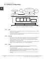
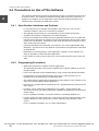
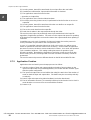
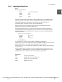
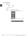
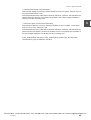
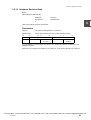
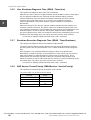
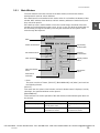
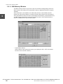
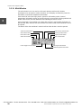
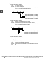
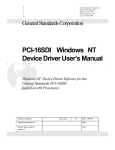
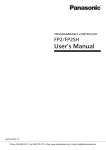
Download Toshiba Computer Module C2/C3 Windows NT Version User`s Manual

Transcript
6F8C0894
model 2000/3000
Computer Module C2/C3 Windows NT Version User's Manual
CTi Automation - Phone: 800.894.0412 - Fax: 208.368.0415 - Web: www.ctiautomation.net - Email: [email protected]
Important Information
No patent liability is assumed by TOSHIBA Corporation with respect to use of information, illustrations,
circuits, equipment or examples of application in this publication.
TOSHIBA Corporation reserves the right to make changes and improvements to this publication and/or
related products at any time without notice. No obligation shall be incurred other than as noted in this
publication.
This publication is copyrighted and contains proprietary material. No part of this book may be reproduced,
stored in a retrieval system, or transmitted, in any form or by any means — electrical, mechanical,
photocopying, recording, or otherwise — without obtaining prior written permission from TOSHIBA
Corporation.
PROSEC, TOSLINE and TOSDIC are trademarks or registered trademarks of TOSHIBA Corporation.
IBM is a registered trademark of International Business Machines Corporation.
Microsoft, MS-DOS, Windows and Windows NT are registered trademarks of Microsoft Corporation in the
U.S.A. and other countries.
Ethernet is a registered trademark of Xerox Corporation.
DeviceNet is a trademark of the Open DeviceNet Vender Association, Inc.
 TOSHIBA CORPORATION 2001. All rights reserved
CTi Automation - Phone: 800.894.0412 - Fax: 208.368.0415 - Web: www.ctiautomation.net - Email: [email protected]
Safety Precautions
This manual contains important information for the operator to operate this product safely and correctly
and avoid bodily injury and property damage.
Grasp the meanings of the following marks and their descriptions before reading this manual.
Hazard Classifications
WARNING
Indicates a potentially hazardous situation which, if not avoided,
could result in serious injury or death.
CAUTION
Indicates a potentially hazardous situation which, if not a avoided,
can result in minor or moderate injury, or property damage. It can
also be used to alert against unsafe practices.
Note: 1. Serious injury means loss of sight, injury, burns (high temperature, low temperature), electrical
shock, fracture, or intoxication which leaves aftereffects or requires hospitalization or need to
go to the hospital for a long time.
2. Injury means hurt, burn, or electrical shock which does not require hospitalization or going to
the hospital for a long time.
3. Property damage means extended breakdown of assets and materials.
Notation of Markings
Prohibited
Indicates a "may not" mark.
The concrete forbiddance is indicated with a pictograph or wording.
Mandatory
Indicate a mandatory action that you should never fail to do.
The concrete content is indicated inside or near the circle with a
pictograph or wording.
Caution
Indicates a caution.
The concrete content is indicated inside or near the triangle.
Note: The description of forbiddance, mandatory, and caution marks are subject to change, depending
on the labels on the main unit.
CTi Automation - Phone: 800.894.0412 - Fax: 208.368.0415 - Web: www.ctiautomation.net - Email: [email protected]
6F8C0894
i
1. Safety Precautions during Installation
WARNING
Mandatory
Make certain to ground the transmission
paths by grounding with 100ɹ or less ground
resistance exclusively for each segment.
Ground at one point.
Noncompliance may cause transmission
errors.
Noncompliance may cause an electric shock
or a fire.
Mandatory
Do not impress high voltage to a connector or
a terminal board exceeding rated voltage,
such as 100V AC. Always connect to correct
polarity. Incorrect polarity may cause an electric shock or a fire.
CAUTION
Mandatory
Avoid installing or storing the controller in the
following environment:
• A dusty place.
• A place in which a corrosive gas (SO2, H2S)
or combustible gas generates.
• A place subjected to vibration or shocks
exceeding permissible values.
• A place that causes condensation due to
sudden temperature changes.
• Low or high temperature outside of
installation conditions.
• High humidity outside of installation
conditions.
• Direct sunshine.
• Near equipment that emits a strong radio
wave or magnetic field.
Mandatory
Install the equipment in a place affording
easy maintenance servicing and checks.
Otherwise, a trouble may be caused during
a failure, resulting in a major accident.
Forbidden
Do not block the ventilation port or suction/
exhaust port of the equipment.
Otherwise, overheating or other phenomena may cause a fire or a failure.
Mandatory
Mandatory
Noncompliance with the installation
conditions described in this manual during
system installation or wiring may disable
the controller to demonstrate its design
performance and may cause equipment
malfunction or failures.
Always install the module after turning the
external power supply off. Otherwise, the
module failure or an electric shock may
result.
CTi Automation - Phone: 800.894.0412 - Fax: 208.368.0415 - Web: www.ctiautomation.net - Email: [email protected]
ii
model 2000/3000 Computer Module C2/C3 Windows NT Version
2. Safety Precautions during Maintenance Servicing or Checks
WARNING
Mandatory
Always turn the power off when plugging or
unplugging a module or a board, or when
connecting equipment.
Otherwise, an electric shock accident or
equipment failure may result.
Mandatory
Make certain that the external power is turned
off before mounting or dismounting the
module after installing cables in it.
Otherwise, an electric pole will appear on the
backside of the external terminal board,
potentially causing an electric shock.
CAUTION
Forbidden
Exercise reasonable care and do not drop, collide with other article or apply a strong shock
to the equipment or a board.
Otherwise, a failure may result.
Mandatory
Place a conducting mat or a conducting bag
(bag containing a spare board or other part) on
a grounded table and put a board or the
module removed from a unit or a base unit on
the table.
Otherwise, parts may be damaged by static
electricity or other phenomenon.
Mandatory
Discharge static electricity charged on human
body by touching a grounded metal before
touching the equipment or a board.
Otherwise, static electricity may cause
equipment malfunction or a failure.
Forbidden
Do not use benzine, thinner or other solvent
when cleaning a module or a board.
Otherwise, a panel, module or board may
deform or discolor.
Mandatory
Clean equipment, a module or board dirtiness
using a soft cloth. Use a cloth moistened with
water and wringed if dirtiness is stiff.
The equipment, the module or a board left
dirty may cause a wrong decision or
malfunction.
CTi Automation - Phone: 800.894.0412 - Fax: 208.368.0415 - Web: www.ctiautomation.net - Email: [email protected]
6F8C0894
iii
3. Safety Precautions in Replacing Parts with Ended Life
WARNING
Mandatory
Make certain to set the switch of any
equipment to the OFF position before replacing
a power fuse or an alarm fuse installed in the
equipment.
Otherwise, an electric shock or a fire may
result.
4. Safety Precautions in Daily Operation
WARNING
Mandatory
Make certain to check that the power supply
capacity, frequency, voltage and regulation
meet the equipment specification.
Otherwise, the controller will not be able to
demonstrate its design performance and may
cause equipment damage, a fire due to
overheating, or other trouble.
Mandatory
In case the ambient or internal temperature of
the equipment increases abnormally or the
equipment fails, stop operating and turn the
power off to the equipment. Then contact the
Toshiba distributor in your area.
Continuing to operate the equipment without
taking any action may result in a fire due to
overheating or other trouble.
CTi Automation - Phone: 800.894.0412 - Fax: 208.368.0415 - Web: www.ctiautomation.net - Email: [email protected]
iv
model 2000/3000 Computer Module C2/C3 Windows NT Version
CAUTION
Forbidden
Do not touch the ICs, terminals, connectors,
solder surfaces or other parts inside the
modules, except the operation section (setting
switches inside the module).
Otherwise, ICs, LSIs or other devices may be
destroyed by static electricity, resulting in a
failure. An injury by the terminal of a parts
lead wire or a burn by a high-temperature part
may result.
Forbidden
Do not bend, pull or twist the power cord or
cable too strongly.
This may cause wire breakage or heating.
Forbidden
Do not insert a metal piece or drop a paper clip
through a clearance in the equipment body.
A fire or other trouble may result.
Forbidden
Do not disassemble or remodel the
equipment, module or a board.
Otherwise, equipment safety may be lost
and equipment malfunction or failure may
potentially result.
5. Safety Precautions During Transportation, Storage and Scrapping
CAUTION
Mandatory
Comply with ordinances or regulations of
the local government in your area when
discarding the product.
Forbidden
When transporting or storing, put the product
in a conducting bag and pack it in a crated
box.
Otherwise, a failure may result.
CTi Automation - Phone: 800.894.0412 - Fax: 208.368.0415 - Web: www.ctiautomation.net - Email: [email protected]
6F8C0894
v
Limitation of Applications
The equipment has been designed and manufactured for use in an industrial environment.
However, the equipment is not intended to be used for systems which can endanger human life
(Note 1).
Consult Toshiba if you intend to use the equipment for a special application which involves human
life and has great influence on the maintenance of the public function (Note 2). This is why such
application requires special care on the operation, maintenance, and control of the system (Note 3).
(Note 1) The systems which can endanger human life are life maintenance systems, equipment
installed in the surgery, and other medical equipment.
(Note 2) The systems which involve human life and have great influence on the maintenance of the
public function mean the main control system of a nuclear power plant, safety and
protection system of a nuclear power facility, transport operation and control systems for
mass transportation, control systems of aviation and space systems, and other systems
and subsystems where safety is critical.
(Note 3) "Special care" means to build a safety system (foolproof design, fail safe design,
redundancy design, etc.) in full consultation with Toshiba's engineers.
Immunity
Toshiba is not liable for any loss caused by fire, earthquake, action by a third party, or other
accidents, or the operator's intentional or accidental misuse, incorrect use, or use under abnormal
condition.
Toshiba is not liable for any incidental loss caused by the use or non-use of this product, such as
loss of business profits, suspension of business, or loss or change of data on memory.
Toshiba is not liable for the loss caused by an operation contradictory to any of the instructions
stated in this manual.
Toshiba is not liable for the loss caused by an incorrect operation in combination with other
equipment.
Toshiba is not liable for the loss caused by a malfunction in combination with an application program
made by the customer.
NOTE:
Use cellular phones and PHSs at least one meter away from the working equipment, transmission
cables, and I/O bus cable. Otherwise, the system can malfunction.
CTi Automation - Phone: 800.894.0412 - Fax: 208.368.0415 - Web: www.ctiautomation.net - Email: [email protected]
vi
model 2000/3000 Computer Module C2/C3 Windows NT Version
Preface
The Structure of This Manual
This manual describes Windows NT, the operating system of Microsoft Corporation,
installed in the Computer Modules C2/C3 of the Integrated Controller, with a focus on the
features added or extended to the operating system. The reader is invited to read
manuals of Microsoft for the full information on Windows NT.
This manual is composed of the following chapters:
Chapter 1 Windows NT
Chapter 1 describes initial settings of Windows NT, which is preinstalled, and other
matters.
Chapter 2 I/O Bus Support Software
The C2/C3 can directly control the parallel bus I/O modules. This chapter describes
the I/O bus support features, which control the modules, and API.
Chapter 3 RAS Support Software
This chapter describes the RAS features of the C2/C3 and usage of them.
CTi Automation - Phone: 800.894.0412 - Fax: 208.368.0415 - Web: www.ctiautomation.net - Email: [email protected]
6F8C0894
vii
CTi Automation - Phone: 800.894.0412 - Fax: 208.368.0415 - Web: www.ctiautomation.net - Email: [email protected]
CONTENTS
1 Windows NT . . . . . . . . . . . . . . . . . . . . . . . 1
1.1 Precautions . . . . . . . . . . . . . . . . . . . . . . . . . . . . . . . . . 2
1.2 Initialization . . . . . . . . . . . . . . . . . . . . . . . . . . . . . . . . . 3
1.3 Other Information . . . . . . . . . . . . . . . . . . . . . . . . . . . . . 4
2 I/O Bus Support Software . . . . . . . . . . . . 5
2.1 Software Installation . . . . . . . . . . . . . . . . . . . . . . . . . . 6
2.2 Hardware Configuration . . . . . . . . . . . . . . . . . . . . . . . . 7
2.3 Software Configuration . . . . . . . . . . . . . . . . . . . . . . . . 8
2.3.1 API . . . . . . . . . . . . . . . . . . . . . . . . . . . . . . . . . . . . . . 8
2.3.2 Service . . . . . . . . . . . . . . . . . . . . . . . . . . . . . . . . . . . 8
2.3.3 Tool . . . . . . . . . . . . . . . . . . . . . . . . . . . . . . . . . . . . . 8
2.3.4 G3 I/O Driver . . . . . . . . . . . . . . . . . . . . . . . . . . . . . . 9
2.4 Precautions on Use of This Software . . . . . . . . . . . . 10
2.4.1 Specification Limitations and Cautions . . . . . . . . . 10
2.4.2 Programming Precautions . . . . . . . . . . . . . . . . . . . 10
2.4.3 Comparison with S2/S3 . . . . . . . . . . . . . . . . . . . . . 11
2.4.4 Purchasing and Development Environment . . . . . . 11
2.5 Support Input/Output Module . . . . . . . . . . . . . . . . . . 12
2.6 API . . . . . . . . . . . . . . . . . . . . . . . . . . . . . . . . . . . . . . . 14
2.6.1 Basic Processing Flow . . . . . . . . . . . . . . . . . . . . . . 14
2.6.2 List of APIs . . . . . . . . . . . . . . . . . . . . . . . . . . . . . . . 16
2.7 Batch Input/Output . . . . . . . . . . . . . . . . . . . . . . . . . . . 17
2.7.1 Operating Principles . . . . . . . . . . . . . . . . . . . . . . . . 17
2.7.2 Application Creation . . . . . . . . . . . . . . . . . . . . . . . . 18
2.7.3 Service Registry . . . . . . . . . . . . . . . . . . . . . . . . . . . 19
2.7.4 mutex (Exclusive Control) . . . . . . . . . . . . . . . . . . . 19
2.8 RAS Feature . . . . . . . . . . . . . . . . . . . . . . . . . . . . . . . 20
2.8.1 Self-Diagnosis . . . . . . . . . . . . . . . . . . . . . . . . . . . . 20
2.8.2 Event Log . . . . . . . . . . . . . . . . . . . . . . . . . . . . . . . . 20
2.9 API References . . . . . . . . . . . . . . . . . . . . . . . . . . . . . 23
2.9.1 CreateFile . . . . . . . . . . . . . . . . . . . . . . . . . . . . . . . 23
2.9.2 CloseHandle . . . . . . . . . . . . . . . . . . . . . . . . . . . . . 23
2.9.3 IobusGetMappedinfo . . . . . . . . . . . . . . . . . . . . . . . 24
2.9.4 IobusSetDiag . . . . . . . . . . . . . . . . . . . . . . . . . . . . . 24
2.9.5 IobusResetDiag . . . . . . . . . . . . . . . . . . . . . . . . . . . 24
2.9.6 IobusRegCallbackFunc . . . . . . . . . . . . . . . . . . . . . 25
2.9.7 IobusRecvData . . . . . . . . . . . . . . . . . . . . . . . . . . . 26
2.9.8 Remark . . . . . . . . . . . . . . . . . . . . . . . . . . . . . . . . . 26
2.9.9 IobusSendData . . . . . . . . . . . . . . . . . . . . . . . . . . . 27
2.9.10 IobusRecvDataDirect . . . . . . . . . . . . . . . . . . . . . . 28
6F8C0894
ix
CONTENTS
2.9.11 IobusSendDataDirect . . . . . . . . . . . . . . . . . . . . . .29
2.9.12 IobusGetDiagInfo . . . . . . . . . . . . . . . . . . . . . . . . .30
2.9.13 IobusDoBusReset . . . . . . . . . . . . . . . . . . . . . . . .31
2.9.14 IobusModuleSuspend . . . . . . . . . . . . . . . . . . . . . .31
2.9.15 IobusModulResume . . . . . . . . . . . . . . . . . . . . . . .32
3 RAS Support Software . . . . . . . . . . . . . . 33
3.1 Overview of RAS Support Software . . . . . . . . . . . . . . 33
3.1.1 Features of RAS Hardware Processing . . . . . . . . .33
3.1.2 Function to Inform User of Interruption . . . . . . . . . .33
3.1.3 Automatic Shutdown Function . . . . . . . . . . . . . . . .34
3.1.4 RAS Information Processing Function . . . . . . . . . .34
3.1.5 Get DIP Switch State . . . . . . . . . . . . . . . . . . . . . . .34
3.1.6 LED Lighting Control . . . . . . . . . . . . . . . . . . . . . . .34
3.1.7 Functions of RAS Software Processing . . . . . . . . .34
3.1.8 Software Configuration . . . . . . . . . . . . . . . . . . . . . .35
3.2 RAS Support Commands . . . . . . . . . . . . . . . . . . . . . . 36
3.2.1 Open Command . . . . . . . . . . . . . . . . . . . . . . . . . . .37
3.2.2 Close Command . . . . . . . . . . . . . . . . . . . . . . . . . . .39
3.2.3 RAS Support Software Version Reading
Command . . . . . . . . . . . . . . . . . . . . . . . . . . . . . . .40
3.2.4 RAS Driver Error Information Reading
Command . . . . . . . . . . . . . . . . . . . . . . . . . . . . . . .41
3.2.5 RAS Message Receive Window Setting
Command . . . . . . . . . . . . . . . . . . . . . . . . . . . . . . .44
3.2.6 RAS Message Receive Mail Slot Setting
Command . . . . . . . . . . . . . . . . . . . . . . . . . . . . . . .46
3.2.7 Digital Signal Input Command . . . . . . . . . . . . . . . .48
3.2.8 LED Indication Command . . . . . . . . . . . . . . . . . . .50
3.2.9 User RAS Memory Reading Command . . . . . . . . .51
3.2.10 User RAS Memory Writing Command . . . . . . . . .52
3.2.11 System RAS Memory Reading Command . . . . . .53
3.2.12 WDT Setting Command . . . . . . . . . . . . . . . . . . . .54
3.2.13 User WDT Reset Command . . . . . . . . . . . . . . . . .55
3.2.14 User Shutdown Command . . . . . . . . . . . . . . . . . .56
3.2.15 CPU Temperature Information Reading
Command . . . . . . . . . . . . . . . . . . . . . . . . . . . . . . .57
3.2.16 CPU Peripheral Temperature Information
Reading Command . . . . . . . . . . . . . . . . . . . . . . . .58
3.2.17 Battery Information Reading Command . . . . . . . .59
3.2.18 Switch Status Read . . . . . . . . . . . . . . . . . . . . . . .60
3.2.19 Hardware Revision Read . . . . . . . . . . . . . . . . . . .61
3.2.20 Main Unit LED Control . . . . . . . . . . . . . . . . . . . . .62
3.2.21 Main Unit LED Control (2) . . . . . . . . . . . . . . . . . .63
x
model 2000/3000 Computer Module C2/C3 Windows NT Version
CONTENTS
3.3 RAS Support Software Registering . . . . . . . . . . . . . . 64
3.3.1 Registry information of RAS drive . . . . . . . . . . . . . 64
3.3.2 Registry information of RAS service . . . . . . . . . . . 64
3.3.3 Registry information of RAS window . . . . . . . . . . . 65
3.3.4 System WDT(XRAS : SystemWdt) . . . . . . . . . . . . 65
3.3.5 Service Shutdown Diagnosis Time
(XRAS : TimerService) . . . . . . . . . . . . . . . . . . . . . 65
3.3.6 User Shutdown Diagnosis Time
(XRAS : TimerUser) . . . . . . . . . . . . . . . . . . . . . . . 66
3.3.7 Shutdown Execution Diagnosis Time
(XRAS : TimerShutdown) . . . . . . . . . . . . . . . . . . . 66
3.3.8 RAS Service Thread Priority
(XRASService : ServicePriority) . . . . . . . . . . . . . . 66
3.3.9 RAS Message ID (XRASService : MessageID) . . . 67
3.3.10 RAS Mail Slot Name
(XRASService : MailslotName) . . . . . . . . . . . . . . . 67
3.3.11 RAS Mail Slot Receiving Diagnosis Time
(XRASService : MailslotReadTimeOut) . . . . . . . . 67
3.3.12 Forced Shutdown Diagnosis Time
(XRASService : TimerForceShutdown) . . . . . . . . . 67
3.3.13 RAS Window Start Style
(XRASWindow : Startup) . . . . . . . . . . . . . . . . . . . . 68
3.3.14 RAS Window Object Name
(XRASWindow : ObjectName) . . . . . . . . . . . . . . . 68
3.3.15 Normal Window Position (X)
(XRASWindow : NormalPos.x) . . . . . . . . . . . . . . . 68
3.3.16 Normal Window Position (Y)
(XRASWindow : NormalPos.y) . . . . . . . . . . . . . . . 68
3.3.17 Mini Window Display Level
(XRASWindow : MiniLevel) . . . . . . . . . . . . . . . . . . 68
3.3.18 Mini Window Position (X)
(XRASWindow : MiniPos.x) . . . . . . . . . . . . . . . . . . 68
3.3.19 Mini Window Position (Y)
(XRASWindow : MiniPos.y) . . . . . . . . . . . . . . . . . . 68
3.3.20 RAS Include File Install Path
(XRASWindow : InstPathInclude) . . . . . . . . . . . . . 68
3.3.21 RAS Library File Install Path
(XRASWindow : InstPathLibrary) . . . . . . . . . . . . . 69
3.3.22 Option (XRAS : Option) . . . . . . . . . . . . . . . . . . . . 69
3.4 RAS Shutdown Processing . . . . . . . . . . . . . . . . . . . . 70
3.4.1 Shutdown Operation . . . . . . . . . . . . . . . . . . . . . . . 70
3.4.2 Restrictions on WindowsNT shutdown in the
RAS Support Software . . . . . . . . . . . . . . . . . . . . . 71
3.5 RAS Windows . . . . . . . . . . . . . . . . . . . . . . . . . . . . . . 72
3.5.1 Main Window . . . . . . . . . . . . . . . . . . . . . . . . . . . . . 73
3.5.2 Status Window . . . . . . . . . . . . . . . . . . . . . . . . . . . . 75
3.5.3 Service . . . . . . . . . . . . . . . . . . . . . . . . . . . . . . . . . . 77
6F8C0894
xi
CONTENTS
3.5.4 Application . . . . . . . . . . . . . . . . . . . . . . . . . . . . . . .77
3.5.5 Sensor Detection . . . . . . . . . . . . . . . . . . . . . . . . . .78
3.5.6 Operation Environment . . . . . . . . . . . . . . . . . . . . .79
3.5.7 DIO Window . . . . . . . . . . . . . . . . . . . . . . . . . . . . . .79
3.5.8 LED Indication Color Setting . . . . . . . . . . . . . . . . .80
3.5.9 WDT Window . . . . . . . . . . . . . . . . . . . . . . . . . . . . .81
3.5.10 Alarm Window . . . . . . . . . . . . . . . . . . . . . . . . . . .81
3.5.11 RAS Memory Window . . . . . . . . . . . . . . . . . . . . .82
3.5.12 Event Log Window . . . . . . . . . . . . . . . . . . . . . . . .85
3.5.13 Refresh button . . . . . . . . . . . . . . . . . . . . . . . . . . .85
3.5.14 Event log information . . . . . . . . . . . . . . . . . . . . . .86
3.5.15 Registry Window . . . . . . . . . . . . . . . . . . . . . . . . .87
3.5.16 Driver Related Button . . . . . . . . . . . . . . . . . . . . . .87
3.5.17 Window Related Button . . . . . . . . . . . . . . . . . . . .89
3.5.18 Mini-Window . . . . . . . . . . . . . . . . . . . . . . . . . . . . .90
3.5.19 Window buttons . . . . . . . . . . . . . . . . . . . . . . . . . .91
3.6 Event Log Information . . . . . . . . . . . . . . . . . . . . . . . . . 92
3.6.1 Logging Information When RAS Service Starts . . .92
3.6.2 Logging Information during Operation of
RAS Service . . . . . . . . . . . . . . . . . . . . . . . . . . . . .92
3.6.3 Logging Information at End of RAS Service . . . . . .93
3.6.4 Event Log List . . . . . . . . . . . . . . . . . . . . . . . . . . . . .93
3.6.5 Event Log Detail . . . . . . . . . . . . . . . . . . . . . . . . . . .94
xii
model 2000/3000 Computer Module C2/C3 Windows NT Version
Chapter 1 Windows NT
1
This chapter describes cautions and other matters in using Windows NT4.0 on the
Computer Modules of the Integrated Controller.
The reader is invited to read manuals published by Microsoft and books sold in
bookstores for the full information on Windows NT.
CTi Automation - Phone: 800.894.0412 - Fax: 208.368.0415 - Web: www.ctiautomation.net - Email: [email protected]
6F8C0894
1
Chapter 1 Windows NT
1
1.1 Precautions
Power Supply
Turning the power off before normal ending of Windows NT may damage the file system
and important files. In the worst case, Windows NT cannot potentially be started.
Make certain to execute finish processing of Windows NT before turning the power off.
Also, make certain to supply the power that is always stable.
Detection of Abnormal Temperature
If the operating environment is not suitable, the inside temperature of the main unit may
exceed the specified value, which potentially presents a hazard of a system fault due to
equipment malfunction.
The C2/C3 monitors the CPU temperature through the RAS feature and generates an
alarm in case the temperature exceeds a preset value (currently 55oC), to notify a
trouble. It is strongly recommended that application systems incorporate a program that
detects this alarm. The program should inform the operator about a trouble and stop the
system till the cause for a temperature error is removed when it receives such notice.
See the XrasUserWindow Command in "RAS Support Software" in chapter 3 for a
method to detect a temperature error by a specific application program.
File Backing Up
Back up important files from time to time by copying files into backup files. Important files
cannot be restored in case they are lost by an unanticipated accident, unless they are
stored in backup files.
Changing Registry Value
Changes of the registry, which stores set values and registration information of Windows
NT require very careful execution. If an error is made in making a change, system
startup may be disabled.
Service Pack1 Installation
Reinstall the Service Pack when the system configuration is added or changed, such as
network protocol addition.
Caution for setting memory space addresses for PCMCIA card
Note that memory addresses 0xC8000 to 0xCA000 cannot be used for a PCMCIA card
or other card when mounting a card to use memory spaces in PCMCIA slots.
This is not shown in the Windows NT resource display, but a graphic chip also uses these
addresses.
1. A collection of Windows NT bug correction modules supplied by Microsoft. The
Service Pack is stored in the root directory of Drive C in "SP6a" or other name.
CTi Automation - Phone: 800.894.0412 - Fax: 208.368.0415 - Web: www.ctiautomation.net - Email: [email protected]
2
model 2000/3000 Computer Module C2/C3 Windows NT Version
1.2 Initialization
1.2 Initialization
1
When shipped from the factory, Windows NT is set as follows:
Version
Windows NT4.0 Workstation (Build 1381 Service Pack 6)
This is the version as of May 29 2000. The Service Pack version may vary depending on
the release status of Microsoft Corporation.
The Service Pack is stored in the hard disk as C:¥SP6a.
QFE (Quick Fix Engineering)2 also is stored under SP6a. Be sure to install QFE also
after installing SP6a.
Registered User Name
administrator (No password)
Guest (No password)
User management is executed by [User Manager] inside [Control Tool Group] after
logging on by "administrator" when adding a new user or setting or changing a password.
Network
No software setting
When using the 10BASE-T port on the C2/C3 main unit, use the network driver supplied
as an accessory, instead of a Windows NT CD-ROM driver.
Make certain to reinstall the Service Pack after setting the network.
Graphic
Standard VGA Driver
Using the graphic driver supplied as an accessory (NeoMagic MagicGraph 128/Z/ZV),
the C2/C3 accomplishes screen display with a resolution of 1024 x 768 and 65,536 color
pallet colors.
The driver can be installed as follows:
"Control Panel" → "Screen" → "Display Setting" → "Display Type" → select "Change" in
Adapter Type → select "NeoMagic" in Manufacturer → specify "Disk Used"
A correction program to avoid specified faults and problems, which are not contained in
the Service Pack, supplied by Microsoft.
CTi Automation - Phone: 800.894.0412 - Fax: 208.368.0415 - Web: www.ctiautomation.net - Email: [email protected]
6F8C0894
3
Chapter 1 Windows NT
1
1.3 Other Information
Driver Storage Positions
The device drivers and other applications are stored under the following directories
during preinstallation. This directory configuration is the same as that in the backup CDROM.
i386
A device driver supported by Windows NT as a standard
provision.
DRVLIB
A device driver by driver distribution service of CompuServe of
the United States manufactured by a third party.
DRVLIBJ
A device driver manufactured by a third party in Japan
(Japanese version only)
SUPPORT¥USPRNDRV A printer driver supplied with Windows NT of the US version as
a standard provision.
TOSHIBA
A network driver graphic driver for Ethernet port of the main
unit.
SP6a
Service Pack 6a (contains QFE)
A path for the driver storage directory needs be specified when installing a driver or other
application. If the CD-ROM cannot be used when "E:¥i386" or other data is displayed,
execute by specifying "C:¥i386" in the field for path name specification.
These directories store drivers needed in driver installation during a system configuration
change or in other instances. These drivers can be deleted without affecting Windows
NT operation if system configuration changes are not required.
These directories will not be created when the customer reinstalls Windows NT. Specify
driver paths for directories needed for driver installation, to read from the CD-ROM. If the
CD-ROM is assigned to Drive E, specify "E:¥driver path name."
Floppy Disks Attached
The floppy disks supplied with the equipment store modules of various features
described in this manual.
Revision Upgrading
When the version of the preinstalled Windows NT is upgraded, the latest version of
Windows NT has to be purchased separately.
The customer needs to purchase and install the Service Pack separately for revision
upgrading. The latest Service Pack can be purchased at cost through a Web site or from
Microsoft.
CTi Automation - Phone: 800.894.0412 - Fax: 208.368.0415 - Web: www.ctiautomation.net - Email: [email protected]
4
model 2000/3000 Computer Module C2/C3 Windows NT Version
Chapter 2 I/O Bus
Support Software
This chapter describes the I/O bus support software.
2
This software supports data from the C2/C3 input to and output from the various I/O
modules connected to the I/O bus. This software enables direct access of the I/O
modules from Windows NT, thereby easily accomplishing system construction with only
the C2/C3.
The following advantages can be derived by using this software:
• Easy creation of an I/O control application system merging screen control and network
features.
• This means that linkage with SCADA (supervisory control and data acquisition)
software can be accomplished easily.
• An enhanced development environment of Windows NT can be used when creating
an I/O access program.
• Processing of a high parallelism by using multi process and multi thread.
• The same machine can develop and execute programs.
References:
The reader is recommended to read the following documents also after reading this
manual:
• Sequence Controller S3 Main Unit Instruction Manual
(6E8C3783)
• Parallel I/O Instruction Manual
(6E8C3785)
• Pulse Input Module Instruction Manual (PI312)
(6E8C3968)
• Analog Input Module Instruction Manual
(6E8C3969)
• Sequence Controller S2 Hardware Manual
(6E8C3857)
CTi Automation - Phone: 800.894.0412 - Fax: 208.368.0415 - Web: www.ctiautomation.net - Email: [email protected]
6F8C0894
5
Chapter 2 I/O Bus Support Software
2.1 Software Installation
This software is supplied in floppy disks.
2
When reinstalling this software in a machine, in which this software is already installed,
temporarily uninstall (delete) the software and install it again as follows:
START Menu → "Program" → Select "Uninstall" in the holder "Toshiba G310 Support
Software"
After uninstalling, restart the system.
Execute setup.exe stored in the first floppy disks. Then operate by following guidance
messages displayed on the screen.
CTi Automation - Phone: 800.894.0412 - Fax: 208.368.0415 - Web: www.ctiautomation.net - Email: [email protected]
6
model 2000/3000 Computer Module C2/C3 Windows NT Version
2.2 Hardware Configuration
figure 2-1shows the maximum hardware configuration of C3 supported by this software.
Basic Unit
2
576-Points/Basic Base (BU719)
Expansion Units 1-1 to 1-7
Maximum Number of Points for Two Systems
Expansion Units 1-1 to 1-7
Maximum Number of Points for Up To Three Systems
10432 points/When expansion base for 11 boards is used
5962 points/When expansion base for 6 boards is used
15360 points/When expansion base for 11 boards is used
8640 points/When expansion base for 6 boards is used
Expansion Units 1-1 to 1-7
Maximum Number of Points for Up To Four Systems
20288 points/When expansion base for 11 boards is used
11328 points/When expansion base for 6 boards is used
1280 points/When expansion base for 11 boards is used
960 points/When expansion base for 6 boards is used
Expansion Unit
1984 points/When expansion base for 11 boards is used
1344 points/When expansion base for 6 boards is used
Expansion Unit
2688 points/When expansion base for 11 boards is used
1728 points/When expansion base for 6 boards is used
Expansion Unit
3392 points/When expansion base for 11 boards is used
2112 points/When expansion base for 6 boards is used
Expansion Unit
4096 points/When expansion base for 11 boards is used
2496 points/When expansion base for 6 boards is used
Expansion Unit
4800 points/When expansion base for 11 boards is used
2880 points/When expansion base for 6 boards is used
5504 points/When expansion base for 11 boards is used
3264 points/When expansion base for 6 boards is used
Expansion Unit
Figure 2-1 Maximum Hardware Configuration of C3 2 Basic Unit
CTi Automation - Phone: 800.894.0412 - Fax: 208.368.0415 - Web: www.ctiautomation.net - Email: [email protected]
6F8C0894
7
Chapter 2 I/O Bus Support Software
2.3 Software Configuration
2
Win32 Application
Logon Process
Tool
Service
G3 I/O I/F(DLL)
Security
Subsystem
Win32
Sub System
User Mode
Kernel Mode
System Service
Security
Process
Local
Virtual
I/O Manager
Monitor
Manager
Procedure
Memory
G3 I/O Driver
Call
Manager
Kernel
Hardware Abstraction Layer (HAL)
HARDWARE
Figure 2-2 G3 I/O Support Software Configuration
2.3.1
API
The API needed for an application to access an I/O module is mounted as DLL. The file
name of DLL is "g3iolib.dll."
The API provides interfaces for data input and output, various initializations, module error
information acquisition and other purposes.
2.3.2
Service
The service manages startup function registration when interrupts from the application
are generated. In case an I/O module specified for startup is interrupted, the user
function registered in advance is executed. The service manages batch input/output
data between the driver and application.
The parameters to specify operations by the batch input/output feature are stored in the
registry. For the complete information, see "2.7 Batch Input/Output"
2.3.3
Tool
The tool is a GUI tool that operates on Windows NT. Using this tool, the following
settings can be executed and information can be displayed.
(1) Individual mapping
The tool sets the types of mounting slots and modules of the I/O modules. Specify
mounting slots by a channel number, unit or a position inside a unit. Specify module
types by selecting from X, Y, X+Y, iX, iY and iX+Y.
The set information will be stored in the registry and will be looked up when the driver
starts up.
CTi Automation - Phone: 800.894.0412 - Fax: 208.368.0415 - Web: www.ctiautomation.net - Email: [email protected]
8
model 2000/3000 Computer Module C2/C3 Windows NT Version
2.3 Software Configuration
Individual mapping information, which is specified once, can be cancelled and automatic
mapping can be executed.
(2) Display of result of automatic mapping
In case individual mapping is not specified, the driver will execute automatic mapping
when the system is started. The tool displays results of automatic mapping.
2
(3) I/O bus mapping address change
Addresses of a memory space to be used by the I/O bus can be changed.
A change is not required in normal operations. A change is needed only if an address
conflicts when a PC card is used.
The following two addresses can be selected:
A) 0xD0000-0xD7FFF (Default)
B) 0xD8000-0xDFFFF
(4) Setting I/O bus time-out diagnosis time
An I/O bus time-out diagnosis time is set. If ACK is not returned within a preset time, a
hardware error will be declared and subsequent I/O bus accesses will be disabled.
A diagnosis time can be set between 4µs minimum and 60µs maximum in increments of
4µs. Default is set at 32µs.
The following settings can be executed by directly changing registry values using the
registry editor:
• Execute/non-execute on startup of module diagnosis
Whether or not to diagnose faults of the I/O modules executed by the device driver
should be executed beginning system startup can be specified.
Key: DiagStart
Value: 0 (Non-execute on start [default]) or 1 (Execute on start)
If execution is not started on start, diagnosis can be started using the function
"IobusSetDiag."
• Module diagnosis time interval
A time interval to execute the foregoing module diagnosis is specified.
Key: DiagInterval
Value: An integer larger than 0 (in seconds); default value 5
• Number of retry sessions during module error detection
The number of retries executed when an error occurs in module accessing is specified.
The driver tries accessing for the specified number. If errors still continue, the status of
the module is set to "error" and this module will be excluded in subsequent accessing.
By increasing this value, the resistance to temporary module errors increases. However,
the input/output speed will lower.
Key: RetryCount
Value: An integer larger than 0 (in cycles); default value 5
2.3.4
G3 I/O Driver
A G3 I/O access driver that functions as an I/O driver of Windows NT. The driver
processes data input/output from applications via API and initialize requests.
Operations of this driver are transparent to the application program.
CTi Automation - Phone: 800.894.0412 - Fax: 208.368.0415 - Web: www.ctiautomation.net - Email: [email protected]
6F8C0894
9
Chapter 2 I/O Bus Support Software
2.4 Precautions on Use of This Software
This software implements the features provided by S3 and S2 designed exclusively for I/
O module control. The integrated controller basically differs from the so-called PLC in
hardware and software and an application system must be designed heeding to the
following when constructing an application system.
2
2.4.1
Specification Limitations and Cautions
• In case more than one controller are installed in the same basic unit, only one
controller installed in Slot 0 can control the I/O modules.
• The interrupt response time may vary depending on the system environment
(hardware and software configurations and other elements).
• Intervals of interrupts from modules that may generate interrupts such as CDDIs and
intervals of timer interrupts by software must be designed taking the load of the entire
system into consideration. If intervals are too short, the response performance of the
entire system may be lowered.
• A feature equivalent to the fixed-time scan feature in S3 can be implemented using
Win32API. The interval accuracy depends on the features and performance provided
by Windows NT.
• Depending on how the priority is set by application, operation of this software may
delay by operations of other Windows applications.
• If I/O module accessing causes a time-out, scan execution period by the service will
delay.
2.4.2
Programming Precautions
• Application programs are created as Win32 applications.
The application programs call functions supplied by this support software and access
the I/O modules.
• Fixed-cycle interrupts can be implemented by using a feature provided by Win32API.
• In both floating scanning and fixed-time scanning, the control structure such as
repeating has to be described by an application itself.
• The startup timing of application programs that use the features of this software is the
same as in starting ordinary Win32 applications.
• Execution of a program without releasing the CPU will deteriorate the response of the
entire system.
• Functions can be started up by interrupts such as CDDIs. These functions are
executed as threads and a library (libcmt.lib) compatible to multithreads must be linked
during coding.
For the complete information, see the API reference "IobusRegCallbackFunc."
• Function ending and data sending to an actual device of batch output functions in this
support software are not synchronized. Data is stored by output operation of the
service.
For the complete information, see "2.7 Batch Input/Output"
CTi Automation - Phone: 800.894.0412 - Fax: 208.368.0415 - Web: www.ctiautomation.net - Email: [email protected]
10
model 2000/3000 Computer Module C2/C3 Windows NT Version
2.4 Precautions on Use of This Software
2.4.3
Comparison with S2/S3
• The feature "In case one scan processing time exceeds a preset time in fixed-time
scanning, scanning will change to floating scan, but will reset to fixed-time scanning
when the processing time returns" in S2/S3 is not provided. If this processing is
needed, it must be processed by an application program.
• Modes corresponding to HALT, HOLD and DEBUG in mode control processing
provided by S2/S3 are not available.
• Normally operated in a mode corresponding to RUN or RUN-F. The mode will change
to the ERROR mode if a critical error occurs, stopping the access feature.
Whether normal operations correspond to RUN or RUN-F depends on coding of the
application program.
• User data is initialized by data setting by an application program.
• A feature to latch user data in a power failure is not provided.
2.4.4
Purchasing and Development Environment
• This software is authorized to be installed in one each application development
machine and target machine only. The user is requested to kindly purchase this
software for each of target machines in case more than one target machine are used.
• A C/C++ development environment for Windows NT, such as Visual C++ of Microsoft,
needs be purchased in developing application programs.
CTi Automation - Phone: 800.894.0412 - Fax: 208.368.0415 - Web: www.ctiautomation.net - Email: [email protected]
6F8C0894
11
2
Chapter 2 I/O Bus Support Software
2.5 Support Input/Output Module
The input and output modules supported by this software are listed below. For the
complete information of each module, see related information of the I/O modules.
2
model 2000 Support Module
Table 2-1 Output Module
Classification
Transistor Output
Model
Specification
Points
DO633
DC5-24V
16 points
DO634
DC5-24V
32 points
DO635
DC5-24V
64 points
DO633P
DC 12-24V source output
16 points
Triac Output
AC663
AC100-240V
12 points
Contact Output
RO663
AC240V/DC24V
16 points
RO662S
AC 240V/DC 24V independent common
8 points
DA622L
8bit 4 to 20mA/1 to 5V/0 to 10V
2ch
DA622
12bit 4 to 20mA/1 to 5V 15 12bit ±10V
2ch
DA672
12bit ±10V
2ch
Analog Output
Table 2-2 Input Module
Classification
Model
Specification
points
DC/AC Input
DI633
DC/AC 12-24V
16 points
DC Input
DI634
DC24V
32 points
DI635
DC24V
64 points
DI335H
DC 24V high-speed response type
64 points
IN653
AC100-120V
16 points
IN663
AC200-240V
16 points
AD624L
8bit 1 to 5V
4ch
AD624
12bit 1 to 5V
4ch
AD634L
8bit 0 to 10V
4ch
AD338
12bit ±10V
4ch
AC Input
Analog Input
CTi Automation - Phone: 800.894.0412 - Fax: 208.368.0415 - Web: www.ctiautomation.net - Email: [email protected]
12
model 2000/3000 Computer Module C2/C3 Windows NT Version
2.5 Support Input/Output Module
model 3000 Support Module
Table 2-3 Input Module
Classification
DC Input
AC Input
Analog Input
Model
Specification
2
points
DI334
DC12/24V
32 points
DI334H
DC 12/24V high-speed response type
32 points
DI344
DC48V
32 points
DI335
DC24V
64 points
DI335H
DC 24V high-speed response type
64 points
IN354
AC100V
32 points
IN364
AC200V
32 points
AD368
Voltage/current input
8ch
AD318
0 to 5V high-speed type
8ch
AD328
0 to 20mA high-speed type
8ch
AD338
±10V high-speed type
8ch
Status Change
Detection
CD332
DC12/24V
8 points
Pulse Input
PI312
50kbps DC5/12V
2ch
Table 2-4 Output Module
Classification
Transistor Output
Triac Output
Contact Output
Analog Output
Model
Specification
points
DO333
DC24V
16 points
DO334
DC24V
32 points
DO335
DC24V
64 points
DO344
DC48V
32 points
AC363
AC100/200V
16 points
AC364
AC100/200V
32 points
RO364
AC250V/DC30V
32 points
RO363S
AC 250V/DC 30V independent common
16 points
DA364
Voltage output
4ch
DA374
Current output
4ch
CTi Automation - Phone: 800.894.0412 - Fax: 208.368.0415 - Web: www.ctiautomation.net - Email: [email protected]
6F8C0894
13
Chapter 2 I/O Bus Support Software
2.6 API
2.6.1
2
Basic Processing Flow
As a rule, the I/O bus support API is used in the following flow:
(1) Gets a file handle by CreateFile (WIN32 API).
(2) Gets results of automatic mapping by IobusGetMappedinfo. (Option)
(3) Registers callback function for interrupts by IobusRegCallbackFunc. (Option)
(4) Specifies module diagnosis during I/O execution by IobusSetDiag. (Option)
(5) Issues Iobus{RecvData|SendData|RecvDataDirect|SendDataDirect} and executes
batch data input and output and direct input and output.
Executes registration functions when an interrupt generates or at a fixed cycle.
(6) Repeats Step 5) for a necessary number of operations.
(7) Releases the file handle gotten in Step 1) by CloseHandle (WIN32 API) and ends the
flow.
Functions are provided by g3iolib.dll and g3iolib.lib and these functions are prefixed
"Iobus." When using each function, include Header File g3iolib.h.
The files will be stored in the following positions:
C:¥Program Files¥TOSHIBA¥G3IO¥bin¥g3iolib.dll
C:¥Program Files¥TOSHIBA¥G3IO¥include¥g3iolib.h
C:¥Program Files¥TOSHIBA¥G3IO¥lib¥g3iolib.lib
CTi Automation - Phone: 800.894.0412 - Fax: 208.368.0415 - Web: www.ctiautomation.net - Email: [email protected]
14
model 2000/3000 Computer Module C2/C3 Windows NT Version
2.6 API
Directories and libraries are set as follows in Visual C++5.0 (and subsequent versions) of
Microsoft:
• Directory Setting
Set a directory to search header files and library files.
2
(1) Select "Option (O) ..." in the "Tool (T)" Menu.
(2) Select "Directory" Tab.
(3) Select "Include File" in "Directory to Show (S)."
(4) Add "C:¥Program Files¥TOSHIBA¥G3IO¥include" to the new path.
(5) Click "OK" to complete setting.
• Library Setting
(1) Select "Set (S) ..." in the "Project (P)" Menu.
(2) Select "Link" Tab and add g3iolib.lib to "Object/Library Module (L)."
CTi Automation - Phone: 800.894.0412 - Fax: 208.368.0415 - Web: www.ctiautomation.net - Email: [email protected]
6F8C0894
15
Chapter 2 I/O Bus Support Software
2.6.2
List of APIs
The APIs provided by this support software are listed below:
CreateFile(Win32)
2
• Get file handle
CloseHandle(Win32)
• Release file handle
IobusGetMappedinfo
• Get result of automatic mapping
IobusSetDiag
• Specify execution of module diagnosis (Equivalent to I/O error map create feature)
IobusResetDiag
• Reset module diagnosis execute
IobusRegCallbackFunc
• Specify callback function when interrupt is generated
IobusRecvData
• Batch input of data
IobusSendData
• Batch output of data
IobusRecvDataDirect
• Direct data input
IobusSendDataDirect
• Direct data output
IobusGetDiagInfo
• Get result of module diagnosis
IobusDoBusReset
• Issue bus reset command
IobusModuleSuspend
• Set access disable of I/O modules
IobusModulResume
• Reset access disable of I/O modules
CTi Automation - Phone: 800.894.0412 - Fax: 208.368.0415 - Web: www.ctiautomation.net - Email: [email protected]
16
model 2000/3000 Computer Module C2/C3 Windows NT Version
2.7 Batch Input/Output
This section describes operating principles of batch input and output in this support
software and useful information for creating application programs.
2
Mutex
Mutex
Input
File
入力ファ
イル
G3
G3
アプリApplication
ケーション1
1
G3 I/O
I/O
G3
Driver
ドライバ
I/O
I/O
イル
アプリ
ケーション2
2
Application
Output
File
出力ファ
Mutex
Mutex
Figure 2-3 Configuration of Batch Input/Output Software
2.7.1
Operating Principles
Batch input and output is accomplished by interaction among the I/O driver (g3iodrv.sys),
I/O service (g3iosrv.exe), function IobusSendData () and IobusRecvData.
Input and output data is the data that is produced when the input and output registers of
the I/O modules are in a continual state.
• Operation on Input Side
(1) The I/O service accesses each input module through the I/O driver and collects input
data.
(2) Data collected from each input register is stored in an input file as byte streams.
(3) The applications issue Function lobusRecvData.
(4) Exclusive processing (mutex secure) is performed inside the function to access an
input file.
CTi Automation - Phone: 800.894.0412 - Fax: 208.368.0415 - Web: www.ctiautomation.net - Email: [email protected]
6F8C0894
17
Chapter 2 I/O Bus Support Software
(5) Securing mutex, data will be transferred from an input file to the user buffer.
(6) Simultaneous with transfer, input module information is obtained.
(7) The applications return from the function.
• Operation on Output Side
2
(1) The applications issue Function lobusRecvData.
(2) Exclusive processing (mutex secure) is performed inside the function to access an
output file.
(3) Securing mutex, data will be transferred from the user buffer to an output file.
(4) The applications return from the function.
(5) The service reads data from the output file.
(6) Read data is written in the output module through the driver.
The service on the input side periodically stores input module data in the input file
regardless of application operations. The service on the output side queues for updating
of file data from the application and transfers data to the output module when updating is
confirmed.
Completing one cycle each of operation for input and output, the service pauses for
ScanCycle*100ms and proceeds to the next operation cycle.
In case "1" is specified in Registry Value Scan Policy, the service can neither secure
mutex nor perform file exclusive control in file accessing. As the number of application
processes increases, the time to secure mutex also increases. As a result, the operation
cycle sometimes lengthens. This setting avoids phenomena of operation cycles
becoming unstable. Nevertheless, elimination of exclusive control may result in data,
which is being accessed, exchanged with a function and data consistency cannot be
guaranteed.
The service starts and processes different threads on the READ and WRITE sides.
2.7.2
Application Creation
Applications that use batch input and output proceed as follows:
(1) Gets the number of input and output modules and totals of word numbers on the
input and output sides using IobusMappedinfo() and verifies that the numbers agree
with the system configuration.
(2) The input and output sides secure buffers that satisfy the total size of the number of
words on both the input and output sides. The buffers may be secured dynamically
or statically.
(3) Data is input and output using IobusSendData() and Iobus RecvData().
(4) The IO information structure () is externally looked up inside functions and a check is
made whether or not errors have occurred with the modules.
(5) Return to (3).
CTi Automation - Phone: 800.894.0412 - Fax: 208.368.0415 - Web: www.ctiautomation.net - Email: [email protected]
18
model 2000/3000 Computer Module C2/C3 Windows NT Version
2.7 Batch Input/Output
2.7.3
Service Registry
Parameters that specify service scanning operations can be controlled by the registry.
HKEY_LOCAL_MACHINE¥System¥CurrentControlSet¥Services¥g3iosrv
2
• Scan Operation Policy
Specify whether data consistency warranty should be given the priority or the scan cycle
time is given the priority before performing scanning.
Key: Scan Policy
Value: 0 (priority given to data consistency [default]) or 1 (priority given to cycle time)
• Scan Operation Cycle
Specify a time to hibernate after finishing one scan. A short hibernation time achieves
carefully-thought-out I/O, but increases the CPU load, thereby potentially affecting other
processes and threads adversely.
Key: ScanCycle
Value: An integer larger than 1 (in millisecond), default value 5 (500msec)
2.7.4
mutex (Exclusive Control)
In case many processes or threads are requesting access, the service or the function
may not be able to secure mutex. The time-out times for them are fixed at
G3WRITEWAIT and G3READWAIT.
If the service cannot secure Mutex, files are not read or written during this cycle and next
scan operation is processed. If the IobuxSendData/IobusRecvData function cannot
secure Mutex, the function will make an error return, allowing fetching of
ERROR_TIMEOUT by GetLastError().
In case the foregoing event occurs, the function can retry. However, the access
frequency should be adjusted to prevent such time-outs.
CTi Automation - Phone: 800.894.0412 - Fax: 208.368.0415 - Web: www.ctiautomation.net - Email: [email protected]
6F8C0894
19
Chapter 2 I/O Bus Support Software
2.8 RAS Feature
2.8.1
2
Self-Diagnosis
As part of the RAS features of this software, a driver and hardware self-diagnostic feature
is implemented.
Table 2-5 Self-Diagnosis Items (When driver is loaded)
Diagnosis Item
Operation When Trouble is
Detected
Diagnosis
Access Authority Check
Check is made whether or not
Records "No access authority" in
own controller can access the I/O event log. All subsequent data
modules.
input/output requests from
applications will become errors.
I/O Collation Check
If individual mapping is specified,
mapping information and
implementation status are
collated.
Records "Information mismatch"
in event log. All subsequent data
input/output requests from
applications will become errors.
Table 2-6 Self-Diagnosis Items (When application is executed)
Diagnosis Item
2.8.2
Diagnosis
Operation When Trouble is
Detected
MIF Time-Out
Check is made if response
Records "MIF time-out" in event
comes back within specified time log.
during module access.
Module Error Diagnosis
(Option: Can be set/reset
by API)
Module error status is
periodically checked.
Records "error" in module
management table. This
information can be fetched by
API.
Event Log
This software records the following trouble information and alarm messages in the event
log of Windows NT. The event log can be checked using the event viewer.
• The service "Source" will be stored in g3iosrv and in "Application" of the event log.
Table 2-7 Event Log Messages of G3 I/O Service
Category
Information
Warning
Message
Meaning
detect unreaded message
(chan %d, unit %d, mod %d)
Detected that previous interrupt
information is not fetched in a function
when an interrupt was generated from
channel %d, unit %d or module %d. →
Means that "interrupt omission" has
occurred.
No %s module founded
(%s: Input or Output)
An input module or output module does
not exist.
Can't set service version to driver Service driver cannot be registered in the
driver. → It does not affect operation.
No Mailslot created
(chan %d, unit %d, mod %d)
An interrupt was generated from channel
%d, unit %d or module %d, but Mailslot
to notify to function is not created.
Invalid(%s) value(%d).
Use default
Illegal value (%d) was specified by
Registry Key %s. Use an implicit value.
CTi Automation - Phone: 800.894.0412 - Fax: 208.368.0415 - Web: www.ctiautomation.net - Email: [email protected]
20
model 2000/3000 Computer Module C2/C3 Windows NT Version
2.8 RAS Feature
Table 2-7 Event Log Messages of G3 I/O Service
Category
Error (Behind each
message, a
character string for
error cause will be
stored. For
complete
information, see
GetLastError().)
Message
Meaning
StartServiceCtrlDispatcher failed Failed in service start.
2
SetServiceStatus failed
Failed to set service status in Service
Control Manager.
CreateFile(%s) faild(%s: Device
name, file name, etc.)
Failed to open %s.
IobusGetMappedinfo failed
Failed to get I/O module mapping
information.
CreateThread(%s)
failed(%s: Thread name)
Failed to create a thread.
CreateMailslot failed
(chan %d, unit %d, mod %d)
Failed to create Mailslot of chan %d, unit
%d and mod %d.
DeviceIoControl(%s)
failed(%s: IOCTL code)
Failed in DeviceIoControl.
WriteFile(%s)
failed(%s: Mailslot or file)
Failed in WriteFile.
RegOpenKeyEx failed
Failed to open the registry.
RegQueryValueEx(%s)
failed(%s: Registry name)
Failed to get Registry key %s.
malloc(%s)
failed(%s: Execution place)
Failed in malloc (dynamic area secure)
CreateMutex(%s)
failed(%s: mutex name)
Failed to create Mutex.
CreateFileMapping(%s)
failed(%s: File name)
Failed in File %s mapping.
WaitForMultipleObjectEx(%s)
failed(%s: Execution place)
Failed in WaitForMultipleObjectEx.
SetFilePointer(%s)
failed(%s: File name)
Failed to set the file pointer of File %s at
top.
ReadFile(%s)
failed(%s: File name)
Failed to read File %s.
CreateEvent(%s)
failed(%s: Event name)
Failed to generate Event %s.
GetFileTime(%s)
failed(%s: File name)
Failed to get File %s update time.
• The device driver "Source" will be stored in g3iodrv and in "System" of the event log.
CTi Automation - Phone: 800.894.0412 - Fax: 208.368.0415 - Web: www.ctiautomation.net - Email: [email protected]
6F8C0894
21
Chapter 2 I/O Bus Support Software
Table 2-8 Event Log Messages of G3 I/O Device Driver
Category
2
Information
Message
Meaning
Module has been suspended The module has been suspended.
(IobusModSuspend executed)
Module has been resumed
Operation of the module has been
resumed. (IobusModResume executed)
Warning
RESET command executed
G3 I/O bus resetting has been requested.
(IobusDoRest executed)
Error
Can't setup I/O space.
Failed to initialize I/O space.
Can't read registry
Failed to get the Registry.
Can't setup memory space
Failed to initialize memory space.
Can't setup symbolic link.
Failed to create symbolic link.
can't assign resources
Failed to secure resources.
Can't control modules(Invalid Slot mounting position is illegal and
slot)
modules cannot be controlled.
Can't connect interrupt.
Failed to register interrupt.
Module check failed
Module collation produced mismatch.
Detect illegal interrupt
Illegal interrupt has occurred.
CTi Automation - Phone: 800.894.0412 - Fax: 208.368.0415 - Web: www.ctiautomation.net - Email: [email protected]
22
model 2000/3000 Computer Module C2/C3 Windows NT Version
2.9 API References
2.9 API References
2.9.1
CreateFile
2
HANDLE
CreateFile(
LPCSTR
lpszName,
DWORD
fdwAccess,
DWORD
fdwShareMode,
LPSECURITY_ATTRIBUTElpsa,
DWORD
fdwCreate,
DWORD
fdwAttrsAndFlags,
HANDLE
hTemplateFile);
Driver file handle get
Parameters
lpszName
Driver name address
Specify ¥¥.¥g3io.
fdwAccess
Access mode
Specify OR of GENERIC_READ and GENERIC_WRITE.
fdwShareMode
Shared mode
Specify OR of FILE_SHARE_READ and FILE_SHARE_WRITE.
lpsa
Address of security descriptor
Not used. Specify NULL.
fdwCreate
File creating method
Specify OPEN_EXISTING.
fdwAttrsAndFlags File descriptor
Not used. Specify 0 (zero).
hTemplateFile
File handle with attribute to be copied
Not used. Specify NULL.
2.9.2
CloseHandle
BOOL
CloseHandle(
HANDLE
hDevice;
);
Handle reset
Parameters
hDevice
Driver handle gotten by CreateFile.
CTi Automation - Phone: 800.894.0412 - Fax: 208.368.0415 - Web: www.ctiautomation.net - Email: [email protected]
6F8C0894
23
Chapter 2 I/O Bus Support Software
2.9.3
IobusGetMappedinfo
BOOL
IobusGetMappledinfo (
2
HANDLE
hDevice,
struct IOMAP
*iomap
);
Gets results of I/O automatic mapping by the driver.
Parameters
hDevice
Driver handle gotten by CreateFile.
iomap
Pointer to IOMAP structure arrangement.
The arrangement should be 3D arrangement of NCHANNEL X
NUNIT X NMODULE.
2.9.4
IobusSetDiag
BOOL
IobusSetDiag (
HANDLE
hDevice
);
Specifies I/O module diagnosis execute. Execution of this function is equivalent to I/O
error map create function of T3/T3H.
I/O module diagnosis checks the module error status when accessing a module.
Execution of this feature, therefore, increases overhead. Detected module errors can be
gotten by Function IobusGetDiagInfo.
Parameters
hDevice
2.9.5
Driver handle gotten by CreateFile.
IobusResetDiag
BOOL
IobusResetDiag (
HANDLE
hDevice
);
Resets I/O module diagnosis execute specified by IobusSetDiag or the registry. This
function can be called any time.
Parameters
Parameters
hDevice
Driver handle gotten by CreateFile.
CTi Automation - Phone: 800.894.0412 - Fax: 208.368.0415 - Web: www.ctiautomation.net - Email: [email protected]
24
model 2000/3000 Computer Module C2/C3 Windows NT Version
2.9 API References
2.9.6
IobusRegCallbackFunc
BOOL
IobusRegCallbackFunc(
VOID
(__cdecl Func)(void *)
CHAR
cCh,
CHAR
cUnit,
CHAR
cMod,
2
);
Specifies a function to be called when an interrupt generates in a specified module.
Calling this function will create a thread to queue for an interrupt to generate. An
interrupt will create other new thread, which will execute the function Func.
The thread, which called this function, will reset immediately.
Data by interrupt can be selected by looking up the InterruptedData structural
arrangement, which is an internal variable of DLL.
The InterruptedData structure is a structure consisting of the following members:
To look up this structural arrangement, use the Keyword _declspec keyword of the
extended attribute syntax and declare by using the storage class attribute dllimport
unique to Microsoft.
typedef struct InterruptData {
DWORD
TimeStamp;
WORD
Xw;
WORD
Reserved;
} InterruptData_t;
The application to use this function will be the Multithread Application.
The link of the C Run Time Library (libcmt.lib) compatible to multithread will be needed.
Specify Option /MT, /D, or "_X86_" when executing the CL Command.
When Visual C++ is used, specify the Multithread Run Time Library in the Dialog Box
"Project Options."
When creating threads in other place by an application that uses this function, use
_beginthread or _beginthreadex. Do not use CreateThread or ExitThread. For the
complete information, see the section which describes _beginthread.
Parameters:
Func
Function to be started
cCh
Channel No. (0 to 4, 0: Basic unit)
cUnit
Unit No. (0 to 7, 0: Basic unit)
cMod
Module No. (0 to F)
CTi Automation - Phone: 800.894.0412 - Fax: 208.368.0415 - Web: www.ctiautomation.net - Email: [email protected]
6F8C0894
25
Chapter 2 I/O Bus Support Software
2.9.7
IobusRecvData
BOOL
IobusRecvData (
2
HANDLE
hDevice,
WORD
wLength,
WORD
wOffset,
LPWORD
lpwData,
);
Data is input in batch from the input register.
The area specified by pwData must be an area sufficient to store input data.
Parameters:
hDevice
The driver handle gotten by CreateFile.
wLength
Input data length (unit: word)
wOffset
Offset beginning from first data segment of the input register to
access (unit: word)
IpwData
Pointer to input data. Data is handled as continuation of input register
data
Return Values:
When normally ended, a value other than 0 is returned for this function.
When abnormally ended, return 0 and call GetLastError () to know error details.
An ERROR_TIMEOUT generates if mutex cannot be secured during accessing.
2.9.8
Remark
The module data when data is read by issuing this function can be checked by looking up
Symbol ModuleStatus. ModuleStatus is in word arrangement as in arguments used in
Function IobusGetDiagInfo. See IobusGetDiagInfo for the complete information of the
data.
CTi Automation - Phone: 800.894.0412 - Fax: 208.368.0415 - Web: www.ctiautomation.net - Email: [email protected]
26
model 2000/3000 Computer Module C2/C3 Windows NT Version
2.9 API References
2.9.9
IobusSendData
BOOL
IobusSendData (
HANDLE
hDevice,
WORD
wLength,
WORD
wOffset,
LPWORD
lpwData,
2
);
Data is output in batch to the output register.
Parameters:
hDevice
The driver handle gotten by CreateFile.
wLength
Output data length (unit: word)
wOffset
Offset beginning from first data segment of the output register to
access (unit: word)
IpwData
Pointer to output data. Data is written as continuation of output
register data
Return Values:
When normally ended, a value other than 0 is returned for this function.
When abnormally ended, return 0 and call GetLastError () to know error details.
An ERROR_TIMEOUT generates if mutex cannot be secured during accessing.
CTi Automation - Phone: 800.894.0412 - Fax: 208.368.0415 - Web: www.ctiautomation.net - Email: [email protected]
6F8C0894
27
Chapter 2 I/O Bus Support Software
2.9.10 IobusRecvDataDirect
BOOL
IobusRecvDataDirect(
2
HANDLE
hDevicew
CHAR
cChw
CHAR
cUnitw
CHAR
cModw
CHAR
cOffsetw
WORD
wLengthw
LPWORD
lpwData
);
A wLength length is directly input to data pwData from an address specified by cCh,
cUnit, cMod or cOffset.
A check is not made whether or not a module actually exists or an input device exists at
the specified address. This has to be confirmed by an application.
An area sufficient to store the data length specified by wLength must be provided in
IpwData.
Data is input in a unit of word.
Parameters:
hDevice
The driver handle gotten by CreateFile.
cCh
Channel specification
0-
Basic unit
1-
Channel 1
2-
Channel 2
3-
Channel 3
4-
Channel 4
cUnit
Unit No. in each channel (Counted beginning 0)
cMod
Module No. in each unit (Counted beginning 0)
cOffset
Offset inside a module (in unit of word)
wLength
Length of data input (in unit of word)
IpwData
Pointer to input data
CTi Automation - Phone: 800.894.0412 - Fax: 208.368.0415 - Web: www.ctiautomation.net - Email: [email protected]
28
model 2000/3000 Computer Module C2/C3 Windows NT Version
2.9 API References
2.9.11 IobusSendDataDirect
BOOL
IobusSendDataDirect(
HANDLE
hDevice,
CHAR
cCh,
CHAR
cUnit,
CHAR
cMod,
CHAR
cOffset,
WORD
wLength,
LPWORD
lpwData
2
);
Data pwData is directly output to an address specified by cCh, cUnit, cMod or cOffset for
the wLength length.
A check is not made whether or not a module actually exists at the specified address or
the device can output. This has to be confirmed by an application.
Data is output in a unit of word.
Parameters:
hDevice
The driver handle gotten by CreateFile.
cCh
Channel specification
0-
Basic unit
1-
Channel 1
2-
Channel 2
3-
Channel 3
4-
Channel 4
cUnit
Unit No. in each channel (Counted beginning 0)
cMod
Module No. in each unit (Counted beginning 0)
cOffset
Offset inside a module (in unit of word)
wLength
Length of data output (in unit of word)
IpwData
Pointer to output data
CTi Automation - Phone: 800.894.0412 - Fax: 208.368.0415 - Web: www.ctiautomation.net - Email: [email protected]
6F8C0894
29
Chapter 2 I/O Bus Support Software
2.9.12 IobusGetDiagInfo
BOOL
IobusGetDiagInfo (
2
HANDLE
hDevice,
LPWORD
lpwResults
);
Gets results of module diagnosis.
Parameters:
hDevice
The driver handle gotten by CreateFile.
lpwResults
Arrangement area to store diagnostic results
Results one word per unit are stored in the following sequence.
Basic : Unit0
CH1 : Unit1
CH1 : Unit2
• • •
CH1 : Unit7
CH2 : Unit1
• • •
CH3 : Unit1
• • •
CH4 : Unit7
In each word, Bit 1 shows information for Module 1 and information of
Bit 0 to Module 0 is stored.
15
Mod15
1
0
Mod1
Mod0
Mod0 to Mod15: 0 (normal), 1 (abnormal, including not mounted yet)
CTi Automation - Phone: 800.894.0412 - Fax: 208.368.0415 - Web: www.ctiautomation.net - Email: [email protected]
30
model 2000/3000 Computer Module C2/C3 Windows NT Version
2.9 API References
2.9.13 IobusDoBusReset
BOOL
IobusDoBusReset (
HANDLE
2
hDevice
);
Sends a reset signal to the G3 I/O bus.
Parameters:
hDevice
The driver handle gotten by CreateFile.
2.9.14 IobusModuleSuspend
BOOL
IobusModuleSuspend (
HANDLE
hDevice,
CHAR
cCh,
CHAR
cUnit,
CHAR
cMod,
);
Inhibits access of modules specified by cCh, cUnit and cMod. This feature is used when
inhibiting access prior to exchange when changing an I/O module in an online state.
This feature will have no meaning if it is executed with a module already in a suspend
state. This function becomes an error if a specified I/O module does not exist.
Parameters:
hDevice
The driver handle gotten by CreateFile.
cCh
Channel specification
0-
Basic unit
1-
Channel 1
2-
Channel 2
3-
Channel 3
4-
Channel 4
cUnit
Unit No. in each channel (Counted beginning 0)
cMod
Module No. in each unit (Counted beginning 0)
CTi Automation - Phone: 800.894.0412 - Fax: 208.368.0415 - Web: www.ctiautomation.net - Email: [email protected]
6F8C0894
31
Chapter 2 I/O Bus Support Software
2.9.15 IobusModulResume
BOOL
IobusModuleResume (
2
HANDLE
hDevice,
CHAR
cCh,
CHAR
cUnit,
CHAR
cMod,
);
Resets access inhibit of modules specified by cCh, cUnit and cMod. This feature is used
when resuming access by software after completing an I/O module change in an online
state.
This feature will have no meaning if it is executed with a module already in a accessible
state. This function becomes an error if a specified I/O module does not exist.
Parameters:
hDevice
The driver handle gotten by CreateFile.
cCh
Channel specification
0-
Basic unit
1-
Channel 1
2-
Channel 2
3-
Channel 3
4-
Channel 4
cUnit
Unit No. in each channel (Counted beginning 0)
cMod
Module No. in each unit (Counted beginning 0)
CTi Automation - Phone: 800.894.0412 - Fax: 208.368.0415 - Web: www.ctiautomation.net - Email: [email protected]
32
model 2000/3000 Computer Module C2/C3 Windows NT Version
Chapter 3 RAS Support
Software
3.1 Overview of RAS Support Software
3
This support software supports features that enhance the RAS (reliability, availability and
serviceability) performance of the Integrated Controller Computer Module.
3.1.1
Features of RAS Hardware Processing
This support software has the following RAS features related to hardware processing by
the RAS hardware.
• LED lighting control
• RAS memory read and write
• Internal trouble or error detection (Fan stop, abnormal temperature)
• NMI detection (WDT or INZ switch pressed, shutdown request, low voltage)
• System reset (Hardware reset)
• CPU thermometer
• Low battery voltage detection
The RAS hardware uses the following I/O areas and interrupts and must be set to avoid
competition with other expansion boards. If the RAS hardware competes with other
expansion board, operation of the software cannot be guaranteed.
I/O Areas
• 0x0140 - 0x016F
: Basic RAS I/O
• 0x0061, 0x0070 - 0x0071
: NMI control I/O (I/O on the main board)
• 0xC140 - 0xC141
: CPU thermometer I/O
Interrupts
• IRQ5 is used
Aside from hardware processing of the RAS board, this support software has the
following features:
3.1.2
Function to Inform User of Interruption
This informs the user application program of the interruption signal.
The interruption signal is classified into the following two types.
• Maskable interruption: This becomes an interruption signal when it is registered
with the registry. The interruption No. is 5.
• Non-maskable interruption: WDT, Power Supply off, AC voltage decrease or System memory parity error/Multi-bit error becomes the interruption signal.
CTi Automation - Phone: 800.894.0412 - Fax: 208.368.0415 - Web: www.ctiautomation.net - Email: [email protected]
6F8C0894
33
Chapter 3 RAS Support Software
3.1.3
Automatic Shutdown Function
When the non-maskable interruption occurs, the automatic shutdown processing is done.
In the following cases, however, hardware resetting is done.
• When AC voltage decrease, system memory parity error/multi-bit error or PCI bus
system error was detected.
• When the non-maskable interruption continues for about 2 seconds or longer.
3
3.1.4
RAS Information Processing Function
RAS information when starting, during operation, and when ending, is logged in the
WindowsNT event log. It is also possible to write in and read from the non-volatile
memory.
3.1.5
Get DIP Switch State
This feature reads the ON/OFF state of the 4bit DIP switch installed on the front panel of
the equipment.
3.1.6
LED Lighting Control
This software controls LED 0, which is installed as a standard provision, as follows:
Extingu
ished
RAS Service Start
Recovery from
abnormal condition
Green
Abnormality has
occurred
Temperature trouble
recovery
NMI has occurred
Fan stop recovery
Temperature error
Fan stop
Red
3.1.7
Functions of RAS Software Processing
In addition to the hardware processing of the RAS board, this Support Software has RAS
window functions to display and set these RAS information, making it possible to monitor
and control the operatin status of the system.
Also, it has interfaces for user application programs, and it is possible to create user
application programs to cope with system abnormalities, etc. using the RAS function
processing commands or methods. By means of these user functions, it is possible to
construct systems with higher reliability.
CTi Automation - Phone: 800.894.0412 - Fax: 208.368.0415 - Web: www.ctiautomation.net - Email: [email protected]
34
model 2000/3000 Computer Module C2/C3 Windows NT Version
3.1 Overview of RAS Support Software
3.1.8
Software Configuration
This Support Software is a program to operate under the WindowsNT environment, and
consists of the following 5 modules.
• RAS device driver
This device driver operates under the control of the I/O manager of WindowsNT
Executive, and it is a driver program to process access to the RAS board, interruption
from the RAS board, and request from the user application program.
3
• RAS service
Service program to perform processing of messages from the RAS device driver, event
log processing, and shutdown processing.
• RAS window
Window program to display the information of the RAS board and change the registry
information of the RAS Support Software.
• RAS Support Software DLL
Dynamic Link Library (DLL) to make interface between RAS device driver and user
application program (VC, etc.).
User application program
(VC, etc.)
RAS window
Message
RAS service
RAS Support Software DLL
Win32 subsystem
User mode
Kernel mode
System service
Object
manager
Security
Process
manager
Reference
monitor
Local
procedure
Virtual
memory
manager
Call function
I/O manager
File system
Device driver
Network driver
RAS driver
Kernel
Hardware abstraction layer (HAL)
Hardware (RAS board)
Figure 3-1 Functions of RAS Software Processing
CTi Automation - Phone: 800.894.0412 - Fax: 208.368.0415 - Web: www.ctiautomation.net - Email: [email protected]
6F8C0894
35
Chapter 3 RAS Support Software
3.2 RAS Support Commands
The following shows the list of RAS support commands which can be used by the user
application programs (VC++, etc.). The following pages describes the syntax, argument,
returned value, and explanation for each command.
Command name
3
Outline
CreateFile (Win32)
Open command
CloseHandle (Win32)
Close command
XRasGetVersion
RAS support software version reading command
XRasGetDriveError
RAS driver error information reading command
XRasUserWindow
RAS message receive window setting command
XRasUserMailslot
RAS message receive mail slot setting command
XRasDl
Digital signal input command
XRasDO
Digital signal output command
XRasDilnt
DI interruption setting command
XRasPowerLed
Power LED indication command
XRasAlarmMemory
User RAS memory reading command
XRasWriteMemory
User RAS memory writing command
XRasReadSysMemory
System RAS memory reading command
XRasWDT
WDT setting command
XRasResetWDT
User WDT reset command
XRasUserShutdown
User shutdown command
XRasThermometer
CPU temperature information reading command
XRasThermometerEx
CPU peripheral temperature information reading command
XRasBattery
Battery information reading command
XRasGetSwitchStat
Switch status Read
XRasGetHardwareRevision
Har-dware Revision Read
XRasSetLed
Main Unit LED Control
XRasSetLedEx
Main Unit LED Control
The data types explained in the following sections are those defined by WindowsNT, and
for the application program, it is necessary to include windows.h and winioctl.h.
Since the data types, constants, etc. defined by the RAS Support Software are described
in xrasdll.h, the user application program must include this header file as well. For linking
the user application, it is necessary to link XRasDLL.lib (RAS DLL library). These
xrasdll.h and XRasDLL.lib exist under the directory specified when installing.
CTi Automation - Phone: 800.894.0412 - Fax: 208.368.0415 - Web: www.ctiautomation.net - Email: [email protected]
36
model 2000/3000 Computer Module C2/C3 Windows NT Version
3.2 RAS Support Commands
3.2.1
Open Command
Syntax
HANDLE
hDevice;
LPCTSTR
lpszName;
DWORD
fdwAccess;
DWORD
fdwShareMode;
LPSECURITY_ATTRIBUTES
lpsa;
DWORD
fdwCreate;
DWORD
fdwAttrsAndFlags;
HANDLE
3
hTemplateFile;
lpszName = "¥¥¥¥.¥¥XRAS";
fdwAccess = GENERIC_READ | GENERIC_WRITE;
fdwShareMode = FILE_SHARE_READ | FILE_SHARE_WRITE;
lpsa = NULL;
fdwCreate = OPEN_EXISTING;
fdwAttrsAndFlags = 0;
hTemplateFile = NULL;
hDevice = CreateFile(
lpszName,
fdwAccess,
fdwShareMode,
lpsa,
fdwCreate,
fdwAttrsAndFlags,
hTemplateFile );
Argument
lpszName
Driver name address
Set the name of RAS driver (\\.\XRAS).
fdwAccess
Access mode
Set the combination of GENERIC_READ and GENERIC_WRITE.
fdwShareMode
Shared mode
Set the combination of FILE_SHARE_READ and
FILE_SHARE_WRITE.
lpsa
Address of security descriptor
Set NULL as it is not used.
fdwCreate
Creating method
Set OPEN EXISTING.
fdwAttrsAndFlags File descriptor
Set 0 as it is not used.
hTemplateFile
Handle of file with attribute for copying
Set NULL as it is not used.
CTi Automation - Phone: 800.894.0412 - Fax: 208.368.0415 - Web: www.ctiautomation.net - Email: [email protected]
6F8C0894
37
Chapter 3 RAS Support Software
Returned value
If the device could be normally opened, the open handle of the RAS driver is returned.
When error occurred, INVALID_HANDLE_VALUE is returned.
Explanation
3
Command to open the RAS driver.
CTi Automation - Phone: 800.894.0412 - Fax: 208.368.0415 - Web: www.ctiautomation.net - Email: [email protected]
38
model 2000/3000 Computer Module C2/C3 Windows NT Version
3.2 RAS Support Commands
3.2.2
Close Command
Syntax
BOOL
sts;
HANDLE hDevice;
3
sts = CloseHandle( hDevice );
Argument
hDevice
RAS driver open handle
Returned value
If the device could be normally closed, TRUE is returned. When error occurred, FALSE is
returned.
Explanation
Command to close the RAS driver.
CTi Automation - Phone: 800.894.0412 - Fax: 208.368.0415 - Web: www.ctiautomation.net - Email: [email protected]
6F8C0894
39
Chapter 3 RAS Support Software
3.2.3
RAS Support Software Version Reading Command
Syntax
BOOL
sts;
HANDLE hDevice;
3
LPDWORD
lpVersion;
sts = XRasGetVersion( hDevice, lpVersion );
Argument
hDevice
RAS driver open handle
lpVersion
Address to the buffer in which the version is stored
Returned value
If the command is normally completed, TRUE is returned. When error occurs, FALSE is
returned.
Explanation
Command to read the version of the RAS Support Software.
The following shows the format to be stored in the buffer.
31
16 15
8 7
0
Revision No.
Version No.
(Reserved)
In case of V0l.02, 0x01 is entered for the version and 0x02 for the revision.
CTi Automation - Phone: 800.894.0412 - Fax: 208.368.0415 - Web: www.ctiautomation.net - Email: [email protected]
40
model 2000/3000 Computer Module C2/C3 Windows NT Version
3.2 RAS Support Commands
3.2.4
RAS Driver Error Information Reading Command
Syntax
BOOL
sts;
HANDLE hDevice;
3
Pxrasp_GetDriverError lpError;
sts = XRasGetDriverError( hDevice, lpError );
Argument
hDevice
RAS driver open handle
lpError
Address to the buffer in which the RAS driver error
Returned value
If the command is normally completed, TRUE is returned. When error occurs, FALSE is
returned.
Explanation
Command to read the error information of the RAS driver.
The "pointer to buffer in which the RAS driver error information is stored" in the argument
is the pointer to the structure shown below. On the following pages, the members are
explained.
struct
{
ULONG InzErrReg;
// Registering error information
ULONG InzErrAdr;
// Converting error information
ULONG InzErrRes;
// Resource error information
ULONG InzErrInt;
// Interruption error information
ULONG InzErrNmi;
// NMI error information
BOOLEAN RasAlive; // RAS board error information
ULONG RasService; // RAS service error information
} xrasp_GetDriverError;
typedef xrasp_GetDriverError *Pxrasp_GetDriverError;
CTi Automation - Phone: 800.894.0412 - Fax: 208.368.0415 - Web: www.ctiautomation.net - Email: [email protected]
6F8C0894
41
Chapter 3 RAS Support Software
• InzErrReg (registering error information)
This indicates that the information registered in the registry was an abnormal value.
If the registering was abnormal, bit to correspond to that information is set.
In such a case, the default value is used for the registered value for starting up.
The following shows the definition of bits to correspond to information.
IEREG_INTERRUPT Interruption No. abnormality error
3
IEREG_SERVICE
Service shutdown diagnosis time abnormality bit
IEREG_USER
User shutdown diagnosis time abnormality bit
IEREG_SHUTDOWN Shutdown execution diagnosis time abnormality bit
IEREG_SWDT
System WDT abnormality bit
IEREG_HEALTHY
Healthy signal abnormality bit
• InzErrAdr (converting error information)
This indicates that the I/O address used by the RAS Support Software could not be
converted to the address controlled by WindowsNT.
If this error occurs, the RAS Support Software cannot normally operate and no
interruption processing is done (if Power key is turned, power is turned off).
What can be used is only the open, close, version reading, and driver error information
reading commands. The following shows the definition of bits to correspond to the
information.
IEADR_RAS
0x0140 to 0x016F converting disability bit
IEADR_SYSCON
0x0061 converting disability bit
IEADR_NMI
0x0070 to 0x0071 converting disability bit
IEADR_OPL
0x0178 to 0x017B or 0x0388 to 0x038B converting disability bit
IEADR_THM
0xC140 to 0x141 converting disability bit
• InzErrRes (resource error information)
This indicates that the hardware resource to be used by the RAS Support Software could
not be obtained.
This error, like the converting error, restricts the operation of the RAS Support Software.
The following shows the definition of bits to correspond to the information.
IERES_RES
Hardware resource acquisition abnormality bit
IERES_SHUTDOWN Shutdown routine registering abnormality bit
• InzErrInt (interruption error information)
This indicates that the interruption handler of the RAS Support Software could not be
registered. This error, like the converting error, restricts the operation of the RAS Support
Software. The following shows the definition of bit to correspond to the information.
IEINT_CONNECT
Interruption registering abnormality bit
• InzErrNmi (NMI error information)
This indicates that the NMI handler of the RAS Support Software could not be registered.
This error, like the converting error, restrics the operation of the RAS Support Software.
The following shows the definition of bit to correspond to the information.
IENMI_DESCRIPTOR NMI registering abnormality bit
CTi Automation - Phone: 800.894.0412 - Fax: 208.368.0415 - Web: www.ctiautomation.net - Email: [email protected]
42
model 2000/3000 Computer Module C2/C3 Windows NT Version
3.2 RAS Support Commands
• RasAlive (RAS board error information)
This indicates if the RAS board is inserted. If the RAS board is inserted, TRUE is set, or if
it is not inserted, FALSE is set.
This information becomes valid when InzErrAdr, InzErrRes, InzErrInt, and InzErrNmi are
normal. If the RAS board is not inserted, the operation of the RAS Support Software is
restricted, like the converting error.
3
• RasService (RAS service error information)
This indicates if the RAS service is started. If the RAS service is started, a value other
than 0 is set, or if it is started, 0 is set.
This information becomes valid when InzErrAdr, InzErrRes, InzErrInt, and InzErrNmi are
normal and the RAS board is inserted. If the RAS service is not started, the operation of
the RAS Support Software is restricted, like the converting error.
Xrasp_GetDriveError structure, Pxrasp_GetDriverError pointer type, and described
constant (IExxx_xxx) are defined in xrasdll.h.
CTi Automation - Phone: 800.894.0412 - Fax: 208.368.0415 - Web: www.ctiautomation.net - Email: [email protected]
6F8C0894
43
Chapter 3 RAS Support Software
3.2.5
RAS Message Receive Window Setting Command
Syntax
BOOL
sts;
HANDLE hDevice;
3
HWND
hWnd;
sts = XRasUserWindow( hDevice, hWnd );
Argument
hDevice
RAS driver open handle
hWnd
User window handle
Returned value
If the command is normally completed, TRUE is returned. When error occurs, FALSE is
returned.
Explanation
Command for setting the user window to receive messages from the RAS Support
Software.
The following shows messages to be transmitted by the RAS Support Software.
Since WM_USER+ (RAS message ID : registered in registry) is used for the message to
be transmitted, operation to a window using this message ID cannot be guaranteed. In
such a case, the registering of the RAS message ID should be changed. For the window
set with this command, shutdown processing must be done when the NMI message is
received. For this reason, when the window is deleted, it is necessary to issue the
command with NULL set to the user window handle.
• Fan stop (wParam=RASMSG_FAN_STOP)
This is transmitted when the fan stop is detected.
• Fan recovery (wParam=RASMSG_FAN_STOP_RECOVER)
This is transmitted when recovery is made after fan stop is detected.
• Temperature abnormality (wParam=RASMSG_OVER_THERMO)
This is transmitted when temperature abnormality is detected.
• Temperature recovery (wParam=RASMSG_OVER_THERMO_RECOVER)
This is transmitted when recovery is made after temperature abnormality is
detected.
• DI change (wParam=RASMSG_DI0, RASMSG_DI1, RASMSG_DI2, RASMSG_DI3)
RASMSG_DI2, RASMSG_DI3)
This is transmitted when DI change is detected.
CTi Automation - Phone: 800.894.0412 - Fax: 208.368.0415 - Web: www.ctiautomation.net - Email: [email protected]
44
model 2000/3000 Computer Module C2/C3 Windows NT Version
3.2 RAS Support Commands
• Mirroring disk abnormality
(wParam=RASMSG_ILLEGAL_MIRRORDISK0,RASMSG_ILLEGAL_MIRRORDISK1)
This is transmitted when abnormality is detected when the mirroring disk is
connected.
• NMI occurrence (wParam=RASMSG_NMI)
This is transmitted when the first NMI is detected after the system starts up. NMI
factor is set to IParam.
31
5
4
3
2
1
0
IParam
Power KeyOff
RemoteInitialize
WDT occurrence
After receiving this message, the user must do internal shutdown processing and issue
the user shutdown command (XRasUserShutdown) or the user power off command
(XRasUserPowerdown).
After NMI occurrence, the messages of fan stop/recovery, temperature abnormality/
recovery, DI change, and mirroring disk abnormality are not transmitted.
CTi Automation - Phone: 800.894.0412 - Fax: 208.368.0415 - Web: www.ctiautomation.net - Email: [email protected]
6F8C0894
45
3
Chapter 3 RAS Support Software
3.2.6
RAS Message Receive Mail Slot Setting Command
Syntax
BOOL
sts, flag;
HANDLE hDevice;
3
PHANDLE
lpMail;
sts = XRasUserMailslot( hDevice, flag, lpMail );
Argument
hDevice
RAS driver open handle
flag
Mail slot creating flag
lpMail
Address to buffer in which created mail slot handle is stored
Returned value
If the command is normally completed, TRUE is returned. When error occurs, FALSE is
returned.
Explanation
Like the RAS message receive window setting command, this command is to make
preparation for receiving messages from the RAS Support Software.
In the case of the RAS message receive window setting command, the user application
program to receive the messages must be a window program, but if this command is
used, even a user application program not having such window handle as console
application can receive the messages.
By executing this command, the mail slot to receive messages from the RAS Support
Software is created/deleted.
If TRUE is set to the mail slot creating flag of the argument, the mail slot is created or if
FALSE is set, it is deleted.
To receive the message, firstly create the mail slot with this command and issue the
receive command of Win32 API (ReadFile) to the mail slot handle of the returned value.
Then when the user application receiving the message ends, issue this command and
delete the mail slot.
As the priority for transmitting the RAS messages, the RAS Support Software firstly
checks if there exists the mail slot created with this command.
If it exists, it transmits the messages only to the mail slot. If the mail slot does not exist,
then it checks if the receiving window exists. Thus, even if the receiving window is set,
the message is not transmitted to the receiving window if the receiving mail slot is set.
Like the RAS message receive window setting command, the application program set
with this command requires shutdown processing when the NMI message is received.
For this reason, when the application program ends, it is necessary to delete the mail slot
by issuing this command.
Message data which can be read by using the receive command (ReadFile) are 8 bytes
consisting of message ID and detailed data. They are stored in the buffer as shown
below.
CTi Automation - Phone: 800.894.0412 - Fax: 208.368.0415 - Web: www.ctiautomation.net - Email: [email protected]
46
model 2000/3000 Computer Module C2/C3 Windows NT Version
3.2 RAS Support Commands
+0
Message ID (ULONG)
+4
Detailed data (ULONG)
• Fan stop (message ID : RASMSG_FAN_STOP)
This is transmitted when fan stop is detected.
3
• Fan recovery (message ID : RASMSG FAN_STOP_RECOVER)
This is transmitted when recovery is made after fan stop is detected.
• Temperature abnormality (message ID : RASMSG_OVER_THERMO)
This is transmitted when temperature abnormality is detected.
• Temperature recovery (message ID : RASMSG_OVER_THERMO_RECOVER)
This is transmitted when recovery is made after temperature abnormality is
detected.
• DI change (message ID : RASMSG_DI0, RASMSG_DI1, RASMSG_DI2, RASMSG_
DI3)
This is transmitted when DI change is detected.
• NMI occurrence (message ID : RASMSG_NMI)
This is transmitted when the first NMI is detected after the system starts up. The
NMI factor is set to the detailed data portion. The following shows the content of
the detailed data portion.
31
5
4
3
2
1
0
Detailed data
Power KeyOff
RemoteInitialize
WDT occurrence
After receiving this message, the user must do the internal shutdown processing and
issue the user shutdown command (XRasUserShutdown) or the user power off
command (XRasUserPowerdown).
After NMI occurrence, the messages of fan stop/recovery, temperature abnormality/
recovery, DI change, and mirroring disk abnormality are not transmitted.
CTi Automation - Phone: 800.894.0412 - Fax: 208.368.0415 - Web: www.ctiautomation.net - Email: [email protected]
6F8C0894
47
Chapter 3 RAS Support Software
3.2.7
Digital Signal Input Command
Syntax
BOOL
sts;
HANDLE hDevice;
3
LPDWORD
lpDI;
sts = XRasDI( hDevice, lpDI );
Argument
hDevice
RAS driver open handle
lpDI
Address to the buffer in which the DI information is stored.
Returned value
If the command is normally completed, TRUE is returned. When error occurs, FALSE is
returned.
Explanation
Command to read the state of the digital input signal of the RAS board.
The following figure shows the contents of the DI information stored in the buffer.
CTi Automation - Phone: 800.894.0412 - Fax: 208.368.0415 - Web: www.ctiautomation.net - Email: [email protected]
48
model 2000/3000 Computer Module C2/C3 Windows NT Version
3.2 RAS Support Commands
In C2/C3, DI/DO information does not have any meaning.
Detailed trouble information of each sensor can be read in Bits 31 to 16 of a read value.
• Bits 31 to 24: Data whether each sensor is effective (1) or not effective (0) is stored.
• Bits 23 to 16: Status of each sensor (0: normal/1: abnormal) is stored
.
Bit
24
#0 fan sensor
25
-
26
-
27
-
28
#0 temperature sensor
29
-
30
-
31
-
3
CTi Automation - Phone: 800.894.0412 - Fax: 208.368.0415 - Web: www.ctiautomation.net - Email: [email protected]
6F8C0894
49
Chapter 3 RAS Support Software
3.2.8
LED Indication Command
Syntax
BOOL
sts;
HANDLE hDevice;
3
DWORD
dwLed;
sts = XRasPowerLed( hDevice, dwLed );
Argument
hDevice
RAS driver open handle
dwLed
Power LED indication information
Returned value
If the command is normally completed, TRUE is returned. When error occurs, FALSE is
returned.
Explanation
Command to make green/red the indication color of LED on the front of equipment. The
following figure shows the contents of the LED indication information of the argument.
31
0
Indication color (= 0: green, = 1: red)
The indication may be used by the healthy signal of the RAS Support
Software, and in such a case, care must be taken. The indication when power is turned
on is green.
CTi Automation - Phone: 800.894.0412 - Fax: 208.368.0415 - Web: www.ctiautomation.net - Email: [email protected]
50
model 2000/3000 Computer Module C2/C3 Windows NT Version
3.2 RAS Support Commands
3.2.9
User RAS Memory Reading Command
Syntax
BOOL
sts;
HANDLE hDevice;
DWORD
dwAdr;
DWORD
dwSize;
LPUCHAR
lpBuffer;
3
sts = XRasReadMemory( hDevice, dwAdr, dwSize, lpBuffer );
Argument
hDevice
RAS driver open handle
dwAdr
User RAS memory leading address
dwSize
Number of bytes to be read
lpBuffer
Address of buffer in which data read are stored
Returned value
If the command is normally completed, TRUE is returned. When error occurs, FALSE is
returned.
Explanation
Command to read the data of the user RAS memory portion.
Since the RAS Support Software does not operate this user RAS memory, the user can
use it freely.
The following table shows the range of leading address and the range of the number of
bytes to be read of the argument.
The leading address + number of bytes to be read must not exceed the size of the user
RAS memory.
User RAS memory size
Range of leading
address
Range of number of
bytes to be read
65312 bytes
0-65311
1-256
CTi Automation - Phone: 800.894.0412 - Fax: 208.368.0415 - Web: www.ctiautomation.net - Email: [email protected]
6F8C0894
51
Chapter 3 RAS Support Software
3.2.10 User RAS Memory Writing Command
Syntax
3
BOOL
sts;
HANDLE
hDevice;
DWORD
dwAdr;
DWORD
dwSize;
LPUCHAR
lpBuffer;
sts = XRasWriteMemory( hDevice, dwAdr, dwSize, lpBuffer );
Argument
hDevice
RAS driver open handle
dwAdr
Leading address of system RAS memory
dwSize
Number of bytes to be written
lpBuffer
Address of buffer in which data written are stored
Returned value
If the command is normally completed, TRUE is returned. When error occurs, FALSE is
returned.
Explanation
Command to read the data of the user RAS memory portion.
Since this system RAS memory is used by the RAS Support Software, no writing
can be done.
The leading address of the argument is in the range of 0 to 0xff, and the number of bytes
to be read must be specified within the range of 1 to 0x100.
The addresses 0xe0 to 0xff correspond to 0x00 to 0x1f of user RAS memory, and same
contents can be read.
The leading address + number of bytes to be read must not exceed 0x100.
CTi Automation - Phone: 800.894.0412 - Fax: 208.368.0415 - Web: www.ctiautomation.net - Email: [email protected]
52
model 2000/3000 Computer Module C2/C3 Windows NT Version
3.2 RAS Support Commands
3.2.11 System RAS Memory Reading Command
Syntax
BOOL
sts;
HANDLE
hDevice;
DWORD
dwAdr;
DWORD
dwSize;
LPUCHAR
lpBuffer;
3
sts = XRasReadSysMemory( hDevice, dwAdr, dwSize, lpBuffer );
Argument
hDevice
RAS driver open handle
dwAdr
Leading address of system RAS memory
dwSize
Number of bytes to be written
lpBuffer
Address of buffer in which data written are stored
Returned value
If the command is normally completed, TRUE is returned. When error occurs, FALSE is
returned.
Explanation
Command to read the data of the user RAS memory portion.
Since this system RAS memory is used by the RAS Support Software, no writing
can be done.
The leading address of the argument is in the range of 0 to 0xff, and the number of bytes
to be read must be specified within the range of 1 to 0x100.
The addresses 0xe0 to 0xff correspond to 0x00 to 0x1f of user RAS memory, and same
contents can be read.
The leading address + number of bytes to be read must not exceed 0x100.
CTi Automation - Phone: 800.894.0412 - Fax: 208.368.0415 - Web: www.ctiautomation.net - Email: [email protected]
6F8C0894
53
Chapter 3 RAS Support Software
3.2.12 WDT Setting Command
Syntax
3
BOOL
sts;
HANDLE
hDevice;
DWORD
dwWDT
sts = XRasWDT( hDevice, dwWDT );
Argument
hDevice
RAS driver open handle
dwWDT
WDT setting information
Returned value
If the command is normally completed, TRUE is returned. When error occurs, FALSE is
returned.
Explanation
Command to set Watchdog Timer (WDT).
The time can be set in the range of 524ms (set value1) to 2 minutes and 13 seconds (set
value255) in the units of 524ms. If the set value is 0, WDT is prohibited. WDT setting
cannot be done after NMI occurrence or after shutdown starting.
If the bit 15 of the WDT setting information is 0, the RAS Support Software automatically
reset the WDT by the timer interruption (500ms cycle), but if the bit 15 is 1, no resetting is
done by the RAS Support Software. In such a case, it is necessary for the user
application program to periodically issue the user WDT reset command to reset the WDT.
31
15
7
0
WDT time
Resetting method(=1:user resetting)
At the time of power on, user WDT registered in the registry is operating. In case a user
WDT which was previously registered in the registry is time out, WDT is disabled at the
time power is on.
CTi Automation - Phone: 800.894.0412 - Fax: 208.368.0415 - Web: www.ctiautomation.net - Email: [email protected]
54
model 2000/3000 Computer Module C2/C3 Windows NT Version
3.2 RAS Support Commands
3.2.13 User WDT Reset Command
Syntax
BOOL
sts;
HANDLE
hDevice;
3
sts = XRasResetWDT( hDevice );
Argument
hDevice
RAS driver open handle
Returned value
If the command is normally completed, TRUE is returned. When error occurs, FALSE is
returned.
Explanation
Command to reset the WDT on the RAS board.
This command becomes effective when selected after the user application program reset
the WDT with the WDT setting command. It cannot be used after NMI occurrence.
CTi Automation - Phone: 800.894.0412 - Fax: 208.368.0415 - Web: www.ctiautomation.net - Email: [email protected]
6F8C0894
55
Chapter 3 RAS Support Software
3.2.14 User Shutdown Command
Syntax
3
BOOL
sts;
HANDLE
hDevice;
sts = XRasUserShutdown( hDevice );
Argument
hDevice
RAS driver open handle
Returned value
If the command is normally completed, TRUE is returned. When error occurs, FALSE is
returned.
Explanation
Command to instruct the RAS Support Software to execute the shutdown.
If the NMI occurrence message is received with the RAS message receive window
setting command (XRasUserWindow), the user application program must do its own
shutdown processing and issue this command or the user power off command
(XRasUserPowerdown).
When this command is issued, the RAS Support Software starts the shutdown of
WindowsNT. If this command was not issued with the NMI message despite the fact that
the user's window was set with the RAS message receive window setting
command, the shutdown of WindowsNT is automatically started assuming that this
command was issued, after the elapse of the user shutdown diagnosis time registered
with the registry.
CTi Automation - Phone: 800.894.0412 - Fax: 208.368.0415 - Web: www.ctiautomation.net - Email: [email protected]
56
model 2000/3000 Computer Module C2/C3 Windows NT Version
3.2 RAS Support Commands
3.2.15 CPU Temperature Information Reading Command
Syntax
BOOL
sts;
HANDLE
hDevice;
LPLONG
lpThermo
3
sts = XRasThermometer( hDevice, lpThermo );
Argument
hDevice
RAS driver open handle
lpThermo
Address to buffer in which CPU temperature information is stored
Returned value
If the command is normally completed, TRUE is returned. When error occurs, FALSE is
returned.
Explanation
Command to read the CPU temperature information of a model which supports the CPU
thermometer.
The information read indicates the temperature of -55oC to 125oC in the units of 0.5oC.
CPU temperature
information read
CPU temperature
0x000000FA
125.0oC
0x00000033
25.5oC
0x00000000
0oC
0xFFFFFFFF
-0.5oC
0xFFFFFFCE
-25.0oC
This command is effective only for models with the mechanism of CPU thermometer
(error occurs for other models).
CTi Automation - Phone: 800.894.0412 - Fax: 208.368.0415 - Web: www.ctiautomation.net - Email: [email protected]
6F8C0894
57
Chapter 3 RAS Support Software
3.2.16 CPU Peripheral Temperature Information Reading Command
Syntax
3
BOOL
sts;
HANDLE
hDevice;
LPLONG
lpThermo
sts = XRasThermo( hDevice, lpThermo );
Argument
hDevice
RAS driver open handle
lpThermo
Address to buffer in which CPU peripheral temperature information is
stored
Returned value
If the command is normally completed, TRUE is returned. When error occurs, FALSE is
returned.
Explanation
Command to read the CPU peripheral temperature information of a model which
supports the CPU peripheral thermometer.
The information read indicates the temperature of -55oC to 125oC in the units of 0.5oC.
CPU peripheral temperature
information read
CPU peripheral
temperature
0x000000FA
125.0oC
0x00000033
25.5oC
0x00000000
0oC
0xFFFFFFFF
-0.5oC
0xFFFFFFCE
-25.0oC
This command is effective only for models which support the CPU peripheral
temperature mechanism (error occurs for other models).
CTi Automation - Phone: 800.894.0412 - Fax: 208.368.0415 - Web: www.ctiautomation.net - Email: [email protected]
58
model 2000/3000 Computer Module C2/C3 Windows NT Version
3.2 RAS Support Commands
3.2.17 Battery Information Reading Command
Syntax
BOOL
sts;
HANDLE hDevice;
LPLONG
3
lpBattery
sts = XRasBattery( hDevice, lpBattery );
Argument
hDevice
RAS driver open handle
lpBattery
Address to buffer in which battery information is stored
Returned value
If the command is normally completed, TRUE is returned. When error occurs, FALSE is
returned.
Explanation
Command to read the battery information on the RAS board.
31
7
0
Batteryinformation
(= 1:voltagenormal/= 0:voltageshort)
CTi Automation - Phone: 800.894.0412 - Fax: 208.368.0415 - Web: www.ctiautomation.net - Email: [email protected]
6F8C0894
59
Chapter 3 RAS Support Software
3.2.18 Switch Status Read
BOOL
XRasGetSwitchStat(
HANDLE
hDevice,
LPDWORD
lpdwSwitch
);
3
Gets the status of the 4bit DIP switch of the main unit.
Parameters
hDevice
The driver handle gotten by CreateFile.
IpwSize
Shows status of the DIP switch (1: ON, 0: OFF)
31
•••
3
•••
•••
SW4
2
1
0
SW3
SW2
SW1
SW1: Status of Switch 1
SW2: Status of Switch 2
SW3: Status of Switch 3
SW4: Status of Switch 4
CTi Automation - Phone: 800.894.0412 - Fax: 208.368.0415 - Web: www.ctiautomation.net - Email: [email protected]
60
model 2000/3000 Computer Module C2/C3 Windows NT Version
3.2 RAS Support Commands
3.2.19 Hardware Revision Read
BOOL
XRasGetHardwareRevision(
HANDLE
hDevice,
LPDWORD
lpdwRevision
);
3
Gets the hardware revision information.
Parameters
hDevice
The driver handle gotten by CreateFile.
lpdwRevision
Shows the hardware revision by the following format:
31
F
B
A
8
Peripheral Board
•••••
Revision
Number of
revisions
7
4
3
0
Main Board
Revision
Number of
revisions
The information is composed of the version and number of revisions for the main and
peripheral boards.
Revisions are increased in number: 0 for Version A, 1 for Version B and 2 for Version C.
CTi Automation - Phone: 800.894.0412 - Fax: 208.368.0415 - Web: www.ctiautomation.net - Email: [email protected]
6F8C0894
61
Chapter 3 RAS Support Software
3.2.20 Main Unit LED Control
BOOL
XRasSetLed(
HANDLE
hDevice.
DWORD
dwState
);
3
This software controls lighting of the 4bit LEDs of the main unit.
Parameters
hDevice
The driver handle gotten by CreateFile.
dwState
Specify the LED lighting status by the following format:
3
1
•
•
•
7
COL3
4
COL2
COL1
COL0
3
LED3
0
LED2
LED1
LED0
LED0 - Specify 1: LED0 lit, 0: extinguished
LED1 - Specify 1: LED1 lit, 0: extinguished
LED2 - Specify 1: LED2 lit, 0: extinguished
LED3 - Specify 1: LED3 lit, 0: extinguished
COL0 - Specify 1: LED0 color red, 0: green
COL1 - Specify 1: LED1 color red, 0: green
COL2 - Specify 1: LED2 color red, 0: green
COL3 - Specify 1: LED3 color red, 0: green
Caution
LED 0 cannot be controlled while the RAS service is in operation.
CTi Automation - Phone: 800.894.0412 - Fax: 208.368.0415 - Web: www.ctiautomation.net - Email: [email protected]
62
model 2000/3000 Computer Module C2/C3 Windows NT Version
3.2 RAS Support Commands
3.2.21 Main Unit LED Control (2)
BOOL
XRasSetLedEx(
HANDLE
hDevice,
DWORD
dwState,
DWORD
dwMask
3
);
This software controls lighting of the 4bit LEDs of the main unit individually.
Parameters
hDevice
The driver handle gotten by CreateFile.
dwState
Specify the LED lighting status by the following format:
3
1
•
•
•
7
COL3
4
COL2
COL1
3
COL0
LED3
0
LED2
LED1
LED0
LED0 - Specify 1: LED0 lit, 0: extinguished
LED1 - Specify 1: LED1 lit, 0: extinguished
LED2 - Specify 1: LED2 lit, 0: extinguished
LED3 - Specify 1: LED3 lit, 0: extinguished
COL0 - Specify 1: LED0 color red, 0: green
COL1 - Specify 1: LED1 color red, 0: green
COL2 - Specify 1: LED2 color red, 0: green
COL3 - Specify 1: LED3 color red, 0: green
dwMaskSpecify whether or not LED operation is required by the following mapping.
If "Specified," lighting of the LED is controlled in accordance with specification by
dwState.
If "Not specified," the state before this function is issued will be maintained regardless of
dwState setting.
3
1
•
•
•
7
4
3
0
MASK3 MASK2 MASK1 MASK0
MASK0 - Specify 1: LED0 lit, 0: extinguished
MASK1 - Specify 1: LED1 lit, 0: extinguished
MASK2 - Specify 1: LED2 lit, 0: extinguished
MASK3 - Specify 1: LED3 lit, 0: extinguished
Caution
LED 0 can be controlled while the RAS service is in operation.
The difference with the xRASSetLed function is that this software can control individual LEDs.
CTi Automation - Phone: 800.894.0412 - Fax: 208.368.0415 - Web: www.ctiautomation.net - Email: [email protected]
6F8C0894
63
Chapter 3 RAS Support Software
3.3 RAS Support Software Registering
For the RAS Support Software, it is necessary to register all the following registry
information (they are automatically registered by installing the RAS Support Software).
If the registered value of each entry of parameter is abnormal, it operates using the
default value.
3
3.3.1
Registry information of RAS drive
Under ¥HKEY_LOCAL_MACHINE¥SYSTEM¥CurrentControlSet¥Service¥XRAS
registry key
Value entry name
Type
Default value
ErrorControl
REG_DWORD
0x01
Group
REG_SZ
Extended Base
Start
REG_DWORD
0x02
Type
REG_DWORD
0x01
Version
REG_SZ
Version No. of this Support Software
Under¥HKEY_LOCAL_MACHINE¥SYSTEM¥CurrentControlSet¥Service¥XRAS¥Param
eters registry key
Name
3.3.2
Value entry name
Type
Default value
Interruption No.
Interrupt
REG_DWO RD
0x05
Healthy signal
HealthyDo
REG_DWORD
0x04
System WDT
SystemWdt
REG_DWORD
60
User WDT
UserWdt
REG_DWORD
0
Service shutdown diagnosis time
TimerService
REG_DWORD
60
User shutdown diagnosis time
TimerUser
REG_DWORD
360
Shutdown execution diagnosis time TimerShutdown
REG_DWORD
600
Option
REG_DWORD
0x00
Option
Registry information of RAS service
Under ¥HKEY_LOCAL_MACHINE¥SYSTEM¥CurrentControlSet¥Service¥XRASService
registry key
Value entry name
Type
Default value
DisplayName
REG_SZ
Toshiba RAS Service
ErrorControl
REG_DWORD
0x01
ImagePath
REG_EXPAND_SZ
%SystemRoot%¥system32¥XRassrv.exe
ObjectName
REG_DWORD
LocalSystem
Group
REG_SZ
Extended Base
Start
REG_DWORD
0x02
Type
REG_DWORD
0x110
CTi Automation - Phone: 800.894.0412 - Fax: 208.368.0415 - Web: www.ctiautomation.net - Email: [email protected]
64
model 2000/3000 Computer Module C2/C3 Windows NT Version
3.3 RAS Support Software Registering
Under
¥HKEY_LOCAL_MACHINE¥SYSTEM¥CurrentControlSet¥Service¥XRASService¥Para
meters registry key
Name
3.3.3
Value entry name
Type
Default value
RAS service thread priority
ServicePriority
REG_SZ
Normal
RAS message ID
MessageID
REG_DWORD
0x1000
RAS mail slot name
MailslotName
REG_SZ
XRASMSG
RAS mail slot receiving diagnosis
time
MailslotReadTimeOut
REG_DWORD
60000
Forced shutdown diagnosis time
TimerForceShutdown
REG_DWORD
240
3
Registry information of RAS window
Under
¥HKEY_LOCAL_MACHINE¥SYSTEM¥CurrentControlSet¥Control¥XRASWindowregistry
key
Name
3.3.4
Value entry name
Type
Default value
RAS window start style
Startup
REG_SZ
Normal
RAS window object name
ObjectName
REG_SZ
XRASWINDOW
Normal window position (X)
NormalPos.x
REG_DWORD
0
Normal window position (Y)
NormalPos.y
REG_DWORD
0
Mini window display level
MiniLevel
REG_SZ
TopMost
Mini window position (X)
MiniPos.x
REG_DWORD
0
Mini window position (Y)
MiniPos.y
REG_DWORD
0
RAS include file install path
InstPathInclude
REG_SZ
(No default)
RAS library file install path
InstPathLibrary
REG_SZ
(No default)
System WDT(XRAS : SystemWdt)
This specifies the time of system WDT of the RAS Support Software.
After NMI occurrence, the RAS Support Software sets WDT to be reset with the RAS
service software, regardless of the present WDT state. This WDT is called system WDT.
Should the system WDT be set, the hardware will be reset, and so due care must be
taken. The following shows the setting range. The values are to be set in the units of
524ms.
2(1048ms) to 255(abt. 2 minutes) (Default value is 60 : abt. 30 seconds)
3.3.5
Service Shutdown Diagnosis Time (XRAS : TimerService)
This specifies the diagnosis time of service in shutdown.
After NMI is detected, the RAS driver informs the RAS service of the NMI occurrence.
And the RAS service informs the RAS driver of the receiving. This period is called service
shutdown diagnosis time.
If the RAS service does not respond within this diagnosis time, it is judged that the RAS
service is unable to operate and the hardware will be reset, and so due care must be
taken when setting. The following shows the setting range. The values are to be set in
the units of 500ms.
2(1 second) to 1200(10 minutes) (Default value is 60 : 30 seconds)
CTi Automation - Phone: 800.894.0412 - Fax: 208.368.0415 - Web: www.ctiautomation.net - Email: [email protected]
6F8C0894
65
Chapter 3 RAS Support Software
3.3.6
User Shutdown Diagnosis Time (XRAS : TimerUser)
This specifies the diagnosis time of the user in shutdown.
After NMI occurrence, the RAS Support Software sends the NMI occurrence message to
the user window set with the RAS message receiving window setting command
(XRasUserWindow). The user window receiving the message must do its internal
shutdown processing (data saving, etc.), issue the user shutdown command
(XRasUserShutdown), and instruct the RAS Support Software to shut down the
WindowsNT.
3
After the message is sent, the RAS Support Software monitors the time until the user
shutdown command is issued. This time is called user shutdown diagnosis time. If the
user shutdown command is not issued within this diagnosis time, it is judged that the user
window program is unable to operate, and the RAS Support Software shutdown
processing will proceed as if the user shutdown command was automatically issued. The
following shows the setting range. The values are to be set in the units of 500ms.
2(1 second) to 1200(10 minutes) (Default value is 360 : 3 minutes)
3.3.7
Shutdown Execution Diagnosis Time (XRAS : TimerShutdown)
This specifies the diagnosis time in the shutdown of WindowsNT.
The RAS Support Software monitors the time from the start of WindowsNT shutdown
processing to the end of actual shutdown. This is called shutdown execution diagnosis
time.
If the shutdown is not completed within this diagnosis time, it is judged that the
WindowsNT is unable to operate, and the hardware is reset, and so due care must be
taken when setting. To make this diagnosis time invalid, set OxFFFFFFFF. This is
effective when it is desired to stop the system in the shutdown state (desired not to
reboot the system). (It can be utilize when the UPS function is used) The following shows
the setting range. The values are to be set in the units of 500ms.
2(1 second) to 1200(10 minutes) (Default value is 600 : 5 minutes)
3.3.8
RAS Service Thread Priority (XRASService : ServicePriority)
This specifies the execution priority of the RAS service thread.
The values which can be set are shown below.
Set value
Priority
TimeCritical
31
High
26
Normal (default value)
24
Low
13
CTi Automation - Phone: 800.894.0412 - Fax: 208.368.0415 - Web: www.ctiautomation.net - Email: [email protected]
66
model 2000/3000 Computer Module C2/C3 Windows NT Version
3.3 RAS Support Software Registering
3.3.9
RAS Message ID (XRASService : MessageID)
This specifies the RAS message value to be sent to the user application program by the
RAS Support Software.
This value is added to WM_USER and informed to the window procedure of the user
application program. The following shows the setting range.
0 to 0x7BFF (Default value is 0x1000 : WM_USER+0x1000)
3
The above range is applied when WM_USER is 0x0400, and actually the total of
WM_USER and set value is to be in the range of 0x7FFF or lower.
The program designer of the window to receive the RAS message must set a window
message ID not used.
3.3.10 RAS Mail Slot Name (XRASService : MailslotName)
This specifies the name of the mail slot to be created with the RAS message receiving
mail slot setting command.
For the mail slot name to be specified here, a name not used by other program within the
system must be described.
As the default, the name XRASMSG is set.
3.3.11 RAS Mail Slot Receiving Diagnosis Time (XRASService :
MailslotReadTimeOut)
This specifies the diagnosis time of the receiving command (ReadFile) to the mail slot
created with the RAS message receiving mail slot setting command.
In case of time-out of the receiving command, the error information obtaining command
(GetLastError) returns ERROR_SEM_TIMEOUT.
The values are to be set in the units of ms, and as the default, 60000 (60 seconds) is set.
If 0 is set as the set value, the receiving command immediately ends if there is no
message. If the set value is 0xffffffff, it waits until the message is sent.
3.3.12 Forced Shutdown Diagnosis Time (XRASService :
TimerForceShutdown)
This specifies the diagnosis time in the forced shutdown of WindowsNT.
As the WindowsNT shutdown method, the RAS Support Software takes two steps.
Firstly, it tries to shut down the WindowsNT while informing the application of the
shutdown. If there exists any process which does not respond, the shutdown is
temporarily stopped (dialogue box is displayed and key input is waited for), leading to the
situation that a system of unmanned operation, etc. cannot normally complete the
shutdown. To avoid such a situation, the RAS Support Software provides the diagnosis
time, and at time-out, it forcefully shuts down the WindowsNT (forcefully ends the
application program).
This diagnosis time is called forced shutdown diagnosis time.
Since the shutdown execution diagnosis time (TimerShutdown) is started from the start of
the first shutdown, this forced shutdown diagnosis time must be set shorter than the
diagnosis time to make it effective. If the shutdown execution diagnosis time is shorter,
the equipment is reset before the forced shutdown is made.
If this diagnosis time is too short, the forced shutdown will be executed in the midst of
shutdown, and WindowsNT may not normally be shut down. For the detail, see the
restrictions of "3.4 RAS Shutdown Processing"
The following shows the setting range. The values are to be set in the units of 500ms.
2(1 second) to 1200 (10 minutes) (Default valve is 240 : 2 minutes)
CTi Automation - Phone: 800.894.0412 - Fax: 208.368.0415 - Web: www.ctiautomation.net - Email: [email protected]
6F8C0894
67
Chapter 3 RAS Support Software
3.3.13 RAS Window Start Style (XRASWindow : Startup)
This specifies the start style (normal window/mini window) of the RAS window.
Set value
Normal (default value)
Mini
3
Start style
Normal window
Mini window
3.3.14 RAS Window Object Name (XRASWindow : ObjectName)
This specifies the object name of the object to be used for double start prevention by the
RAS window. The object name specified here must be a name not used by other
program within the system.
As the default, the name XRASWINDOW is set.
3.3.15 Normal Window Position (X) (XRASWindow : NormalPos.x)
This specifies the window position of X axis of the normal window.
The window position shown differs depending on the setting of the display.
The default value is 0, ultimate left side.
3.3.16 Normal Window Position (Y) (XRASWindow : NormalPos.y)
This specifies the window position of Y axis of the normal window. The default value is 0,
highest side.
3.3.17 Mini Window Display Level (XRASWindow : MiniLevel)
This specifies the display level of the mini window.
Set value
Display level
Top
Arranged at the highest level of Z sequence
TopMost (default value)
Arranged always as the front window even when non-active
3.3.18 Mini Window Position (X) (XRASWindow : MiniPos.x)
This specifies the window position of X axis of the mini window. The default value is 0,
ultimate left side.
3.3.19 Mini Window Position (Y) (XRASWindow : MiniPos.y)
This specifies the window position of Y axis of the mini window. The default value is 0,
highest side.
3.3.20 RAS Include File Install Path (XRASWindow : InstPathInclude)
The path name which installed the include file (xrasdll.h) of the RAS Support Software is
recorded. This information is used when uninstalling is done.
RAS include file install path name : XRAS.BAS
CTi Automation - Phone: 800.894.0412 - Fax: 208.368.0415 - Web: www.ctiautomation.net - Email: [email protected]
68
model 2000/3000 Computer Module C2/C3 Windows NT Version
3.3 RAS Support Software Registering
3.3.21 RAS Library File Install Path (XRASWindow : InstPathLibrary)
The path name which installed the library file (XRasDLL.lib) of the RAS Support Software
is recorded. This information is used when uninstalling is done.
3.3.22 Option (XRAS : Option)
This is a set value for future use, and 0 must be set.
3
CTi Automation - Phone: 800.894.0412 - Fax: 208.368.0415 - Web: www.ctiautomation.net - Email: [email protected]
6F8C0894
69
Chapter 3 RAS Support Software
3.4 RAS Shutdown Processing
3.4.1
Shutdown Operation
The RAS Support Software has the function to automatically shut down the WindowsNT
when NMI (excluding voltage decrease system memory parity error/multi-bit error and
PCI bus system error) is detected.
3
The automatic shutdown operation differs depending on whether the user application
program is receiving the RAS messages with the RAS message receiving window setting
command (XRasUserWindow).
1
RAS driver
7
8
2
3
6
5
4
RAS service
User application program
(1) NMI occurrence. The RAS driver sets the system WDT. If the NMI factor is system
memory parity error/multi-bit error, PCI bus system error or voltage decrease, the
information is left in the RAS memory and the hardware is reset.
(2) The RAS driver informs the RAS service of the NMI message. It starts to monitor the
service shutdown diagnosis time (TimerService).
(3) The RAS service informs the RAS driver that the NMI message was received. Then,
the RAS driver clears the service shutdown diagnosis time and starts to monitor the
user shutdown diagnosis time (TimerUser) if there is the RAS message receiving
user or the shutdown execution diagnosis time (TimerShutdown) if there is no user.
Also, the RAS service moves to the processing of [7] if there is no RAS message
receiving user.
(4) The RAS service informs the RAS message receiving user of the NMI occurrence
message.
(5) The RAS message receiving user performs post-processing in the program and
issues the user shutdown command (XRasUserShutdown) or the user power off
command (XRasUserPowerdown).
(6) When the user shutdown command is issued or the user shutdown diagnosis time
time-out occurs, the RAS driver informs the RAS service of the shutdown execution
message. Also it starts to monitor the shutdown execution monitor time
(TimerShutdown).
(7) The RAS service executes the shutdown in the method to inform the application of
the shutdown. Also it starts to monitor the forced shutdown diagnosis time
(TimerForceShutdown).
(8) After the time-out of the forced shutdown diagnosis time, the shutdown is forcefully
done.
CTi Automation - Phone: 800.894.0412 - Fax: 208.368.0415 - Web: www.ctiautomation.net - Email: [email protected]
70
model 2000/3000 Computer Module C2/C3 Windows NT Version
3.4 RAS Shutdown Processing
3.4.2
Restrictions on WindowsNT shutdown in the RAS Support
Software
(1) If the RAS Support Software is started and then stopped (uninstall, etc.), the power
cannot be turned off even if the power key is set to OFF.
This phenomenon is caused by temporarily setting the RAS board circuit. In case the
RAS support software is stopped, shut down Windows NT manually, then temporarily
turn the power off by switching off the power switch located on the backside. By this,
the power is turned off by switching off the switch beginning next operation.
(Windows NT is not shut down)
(2) If the forced shutdown functions and the shutdown is executed in the midst of the
shutdown processing of WindowsNT, the shutdown may not normally be executed.
CTi Automation - Phone: 800.894.0412 - Fax: 208.368.0415 - Web: www.ctiautomation.net - Email: [email protected]
6F8C0894
71
3
Chapter 3 RAS Support Software
3.5 RAS Windows
With the RAS Support Software, the following RAS windows are prepared.
These windows are developed from the main window of the RAS window.
This makes it possible to process the RAS information display and RAS command
execution at the GUI level.
3
RAS window
Description
Status window
Window to display the information of RAS Support Software
DIO window
Window for setting DI information display, DO output, and DI
interruption
WDT window
Window to display present WDT state and set WDT
Alarm window
Window to output alarm sound
RAS memory window
Window for reading/writing of user RAS memory and displaying
system RAS memory
Event log window
Window to display event information on RAS Support Software
Registry window
Window to display and change registry information on RAS
Support Software
DIO window
Statuswindow
WDT window
Main window
Standard size
Small size
Alarmwindow
Registrywindow
RAS memorywindow
Eventlog window
CTi Automation - Phone: 800.894.0412 - Fax: 208.368.0415 - Web: www.ctiautomation.net - Email: [email protected]
72
model 2000/3000 Computer Module C2/C3 Windows NT Version
3.5 RAS Windows
3.5.1
Main Window
The main window is the basic window of the RAS window, and from this window,
development is made to various windows.
If the RAS board is not installed or RAS device driver is not installed, the buttons of DIO
window, WDT window, alarm window, and RAS memory window are made invalid, and
they cannot be opened.
If the desk top area is made smaller or font size is made larger, the whole of the RAS
window may not be displayed on the screen. In such a case, the whole of the window can
be checked by moving the window by selecting the movement of the system control
menu through the keyboard.
Menu
Status window button
RAS memory
window button
DIO window buttonn
Event log
window button
WDT window button
Registry window
button
Alarm test window
button
Mini-window
button
RAS window
end button
• Menu
The menu consists of 3 items, [SELECT], [MINI WINDOW], and [Other], and each has
the following function.
[SELECT]
This menu item is to select a RAS window, and each window name is displayed, and by
selecting it, the specified window can be opened.
[MINI WINDOW]
This menu item is to set the operation of the mini window, and the following two items can
be checked.
No check
Check
Highest level display
Display is made at the highest
level only when active
Always displayed at the highest
level
Mini window start
Main window is displayed when
RAS window is started
Mini window is displayed when
RAS window is started
CTi Automation - Phone: 800.894.0412 - Fax: 208.368.0415 - Web: www.ctiautomation.net - Email: [email protected]
6F8C0894
73
3
Chapter 3 RAS Support Software
[OTHER]
When you select the version information, the version of the RAS window is displayed as
shown in the figure below. By selecting Help, you can view the online help which is
equivalent to this manual.
3
• Window button
Each window is opened by pressing each window button (status, DIO, WDT, RAS
memory, event log, registry).
• Mini window button
By pressing the mini window button, the main window is closed and the mini window is
opened.
• RAS window end button
By pressing the RAS window end button, the RAS window is ended.
CTi Automation - Phone: 800.894.0412 - Fax: 208.368.0415 - Web: www.ctiautomation.net - Email: [email protected]
74
model 2000/3000 Computer Module C2/C3 Windows NT Version
3.5 RAS Windows
3.5.2
Status Window
The status window is to display the status information of the RAS Support Software.
By pressing the [REFRESH] button, the information displayed is updated.
3
CTi Automation - Phone: 800.894.0412 - Fax: 208.368.0415 - Web: www.ctiautomation.net - Email: [email protected]
6F8C0894
75
Chapter 3 RAS Support Software
By pressing the [DETAIL] button, detailed information of the RAS device driver can be
displayed.
Detail on registry information obtaining is
shown.
Normal obtaining
Registry information could be read
correctly.
O btaining error
Registry information could not be read
correctly.
3
Detail on I/O addressconverting isshown.
Normal converting
Addresscould beconverted.
C onverting error
Addresscould notbeconverted.
Detail on starting information of the driver
isshown.
Normal obtaining/registering
Could benormallyobtained/registered.
O btaining/registering error
Could notnormallybebtained/registered.
CTi Automation - Phone: 800.894.0412 - Fax: 208.368.0415 - Web: www.ctiautomation.net - Email: [email protected]
76
model 2000/3000 Computer Module C2/C3 Windows NT Version
3.5 RAS Windows
3.5.3
Service
For the service item, the following information related to the RAS service is displayed.
• Version
The version information of the RAS service is displayed.
• Status
The start information of the RAS service is displayed.
Display
3.5.4
3
Content
Normal
RAS service is normally operating
Not started
RAS service is not started
Unknown
RAS driver is not installed
Application
For the application related item, the following information related to message informing is
displayed.
• RAS window
Display
Content
User window caption and window User window is set
handle
Not started
RAS service is not started
Unknown
RAS driver is not installed
• User window
Display
Content
RAS window caption and window RAS window is normally operating
handle
Not normal starting
User window is not set
Unknown
RAS driver is not installed
• User mail slot handle
Display
Content
User mail slot handle
User mail slot is created
Not used
User mail slot is not created
Unknown
RAS driver is not installed
• Alarm window
Invalid display is made.
CTi Automation - Phone: 800.894.0412 - Fax: 208.368.0415 - Web: www.ctiautomation.net - Email: [email protected]
6F8C0894
77
Chapter 3 RAS Support Software
3.5.5
Sensor Detection
For the sensor detection item, the following information related to internal abnormality
detection is displayed.
In case of a model not supporting each sensor mechanism, respective invalid display is
made.
• Temperature inside equipment
3
Display
Content
Normal
Temperature in equipment is normal
Abnormal
Temperature in equipment is abnormal
Unknown
RAS driver is not installed
• Fan operation status
Display
Content
Normal
Power fan is normally running
Stopped
Power fan is stopped
Unknown
RAS driver is not installed
• CPU peripheral temperature
CPU temperature and CPU peripheral temperature are displayed. In case of a model
not supporting this function, "-oC" is displayed in invalid character.
• Battery information
Battery information is displayed.
Display
Content
Normal
Battery voltage is normal
Short
Battery voltage is shor
Unknown
RAS driver is not installed
CTi Automation - Phone: 800.894.0412 - Fax: 208.368.0415 - Web: www.ctiautomation.net - Email: [email protected]
78
model 2000/3000 Computer Module C2/C3 Windows NT Version
3.5 RAS Windows
3.5.6
Operation Environment
For the operation environment item, the information of the present operation environment
is displayed.
If the RAS service is not started, "unknown" is displayed for the RAS service related
information (RAS service thread priority, RAS message ID, RAS mail slot name, RAS
mail slot receiving diagnosis time, forced shutdown diagnosis time) or if the RAS driver is
not started, "unknown" is displayed for all the information.
Display item
Content
Driver related
Interruption No.
Interruption No. used by RAS board is displayed.
Healthy detection means
Healthy signal output means of RAS Support Software
is displayed.
System WDT time
Set value of each time and actual time
User WDT time
Service shutdown diagnosis time
are displayed.
User shutdown diagnosis time
Shutdown execution diagnosis
time
Service related
3.5.7
RAS service thread priority
Priority of RAS service thread is displayed
RAS message ID
Window message ID used in RAS message informing
is displayed.
RAS mail slot name
Mail slot name used for RAS mail slot is displayed
RAS mail slot receiving diagnosis
time
RAS mail slot receiving diagnosis time is displayed. If
the receiving diagnosis time is infinite, "FOREVER" is
displayed.
Forced shutdown diagnosis time
Set value of forced shutdown diagnosis time and actual
time are displayed.
DIO Window
The DIO Window processes LED 0 display settings on the GUI level. The other features
are for extension and have no meanings.
CTi Automation - Phone: 800.894.0412 - Fax: 208.368.0415 - Web: www.ctiautomation.net - Email: [email protected]
6F8C0894
79
3
Chapter 3 RAS Support Software
3.5.8
LED Indication Color Setting
Item to change the indication color of the power LED#0 on the front panel of equipment.
Selection
3
Selection information
Setting
• Select button
By pressing the select button, selecting the indication color of the LED #0, and
pressing the set button, the color of the LED is actually displayed.
• Selected information
The indication color (green/red) of the power LED selected by pressing the select
button
• Set button
By pressing the set button, the indication color of the LED #0 selected with the select
button is actually displayed in the LED of the front panel of the equipment.
CTi Automation - Phone: 800.894.0412 - Fax: 208.368.0415 - Web: www.ctiautomation.net - Email: [email protected]
80
model 2000/3000 Computer Module C2/C3 Windows NT Version
3.5 RAS Windows
3.5.9
WDT Window
WDT window can process at the GUI level the setting of WDT supported by the RAS
Support Software. When the WDT window is opened, the present set information is
displayed.
If the RAS board is not installed or RAS device driver is not installed, the main window
and mini window buttons are made invalid and this window cannot be opened.
3
Reset selection
button
Setting button
WDT count
WDT time
Reset button
• Reset select button
Button to select the resetting method of WDT. Either system reset or user reset is
selected.
• WDT count
Item to set the count value of WDT. It can be set in the range of 2 to 255 counts (1
count = 524ms). If 0 is set, WDT is prohibited.
• WDT time
The time of the WDT count set is displayed. If WDT is prohibited, nothing is displayed.
• Set button
By pressing the set button, the WDT information set with the reset select button and
WDT count is actually set.
• Reset button
This is valid only when the WDT resetting method is the user reset, and by pressing
this button, WDT resetting can be done.
3.5.10 Alarm Window
The buttons of the main and mini windows are made invalid.
CTi Automation - Phone: 800.894.0412 - Fax: 208.368.0415 - Web: www.ctiautomation.net - Email: [email protected]
6F8C0894
81
Chapter 3 RAS Support Software
3.5.11 RAS Memory Window
The RAS memory window can process at the GUI level the reading/writing of the user
RAS memory and reading of the system RAS memory supported by the RAS Support
Software.
If the RAS board is not installed or the RAS device driver is not installed, the main
window and mini window buttons are made invalid and this window cannot be opened.
3
If the extended RAS memory functions (Operating Time Monitoring, Thermometer Trend,
and NMI Trigger Information) are being executed, the area in the extended memory
which is available to the user becomes smaller.
• System RAS memory
000h to 0DFh of the system RAS memory are displayed. 0E0h - 0FFh are omitted
because of the user RAS memory.
CTi Automation - Phone: 800.894.0412 - Fax: 208.368.0415 - Web: www.ctiautomation.net - Email: [email protected]
82
model 2000/3000 Computer Module C2/C3 Windows NT Version
3.5 RAS Windows
• User RAS memory
User RAS memory is displayed. They correspond to 0E0h - 0FFh of the system RAS
memory.
3
• Refresh button
By pressing the refresh button, the display is updated to the display of the newest RAS
memory information.
• Extension memory button
With a system supporting the extension RAS memory, the extension portion of the
user RAS memory can be displayed/edited by pressing the extension memory button.
With a system not supporting the extension RAS memory, the button is made invalid
and clicking cannot be done.
CTi Automation - Phone: 800.894.0412 - Fax: 208.368.0415 - Web: www.ctiautomation.net - Email: [email protected]
6F8C0894
83
Chapter 3 RAS Support Software
• User memory correction button
By pressing the user memory correction button, the window for writing the user RAS
memory is displayed and the user RAS memory can be changed.
Batch write data
3
Write selection
Address selection
Present value
Byte data
Write button
• Write select
Button to select writing method of the user RAS memory. Either batch writing or byteunit writing is selected.
• Batch data
If writing is done in the user RAS memory by the batch writing method, the data of all
the user RAS memories can be written at once by entering the data in this area and
pressing the write button.
• Address select
When writing is done in the user RAS memory using the byte-unit writing method, the
address of the target user RAS memory is entered in this item.
• Byte data
When writing is done in the user RAS memory using the byte-unit writing method, the
data to be written is entered in this item and the write button is pressed, and then the
data are actually written in the user RAS memory.
• Present value
When writing is done in the user RAS memory using the byte-unit writing method, the
value presently written in the user RAS memory selected with the address select.
• Write button
By pressing the write button, the input data are written in the user RAS memory.
CTi Automation - Phone: 800.894.0412 - Fax: 208.368.0415 - Web: www.ctiautomation.net - Email: [email protected]
84
model 2000/3000 Computer Module C2/C3 Windows NT Version
3.5 RAS Windows
3.5.12 Event Log Window
The event log window displays the event log information logged by the RAS Support
Software. In this window, maximum 256 events are displayed. More old events can be
checked through the event viewer.
3
Event log information
Refresh button
3.5.13 Refresh button
By pressing the refresh button, the display of the event log window is updated to the
newest information.
CTi Automation - Phone: 800.894.0412 - Fax: 208.368.0415 - Web: www.ctiautomation.net - Email: [email protected]
6F8C0894
85
Chapter 3 RAS Support Software
3.5.14 Event log information
The event log information logged by the RAS Support Software is displayed sequentially
from the newest information. By double-clicking on each event of the event log
information with the mouse, the detailed information of the event is displayed.
Time
3
Computer name
Previous event button
Event type
Date
Event ID
Event description
Next event button
Event count
Event source
Event data
• Date
Date of this event log logged is displayed.
• Time
Time of this event log logged is displayed.
• Computer name
The computer name which logged this event log is displayed.
• Event ID
The event message identifier of the RAS Support Software is displayed.
• Event source
The indentifier of the event log logged by the RAS Support Software is displayed.
• Event type
The type (information/warning/error) of this event is displayed.
• Event explanation
The explanation of this event log is displayed.
• Event data
Data attached to this event log are displayed.
• Preceding event button
For moving to a newer event than this event log.
• Next event log
For moving to an older event than this event log.
• Event count
The count value of the event log displayed in this window is displayed.
In case of 1/256 display, there are 256 events in total, and of them, the newest event is
displayed.
CTi Automation - Phone: 800.894.0412 - Fax: 208.368.0415 - Web: www.ctiautomation.net - Email: [email protected]
86
model 2000/3000 Computer Module C2/C3 Windows NT Version
3.5 RAS Windows
3.5.15 Registry Window
The registry window is to set the registry information of the RAS Support Software. When the
registry window is opened, the present set information is displayed.
It should be noted that this registry information is not necessarily same as the information under the
environment of the RAS Support Software now operating (the environment presently in operation
can be checked through the status window).
This setting becomes valid when WindowsNT is shut down once and then restarted.
3
Driver related
button
Window related
button
Expansion RAS memory
functions button
If the log-in user does not have the right to rewrite the registry, all the settings through this
window are made invalid.
3.5.16 Driver Related Button
By pressing the driver related button, the window to set the registry information of the
RAS device driver and RAS service is displayed.
Interrupt number
Healthy Detection
System WDT
User WDT
Service Response Timeout
User Shutdown Timeout
Shutdown Timeout
RAS Service Priority
RAS Message ID
RAS Mailslot Name
RAS Mailslot Timeout
Force Shutdown Timeout
Default button
Apply button
CTi Automation - Phone: 800.894.0412 - Fax: 208.368.0415 - Web: www.ctiautomation.net - Email: [email protected]
6F8C0894
87
Chapter 3 RAS Support Software
• Interruption No.
Interruption No. to be used by the RAS board is set. Numbers other than 5 cannot be
set.
• Healthy signal
Healthy signal outputted by the RAS Support Software is set.
• System WDT
3
System WDT time is set.
• User WDT
User WDT time at starting is set.
• Service diagnosis time
Service shutdown diagnosis time is set.
• User diagnosis time
User shutdown diagnosis time is set.
• Execution diagnosis time
Shutdown execution diagnosis time is set.
• Service priority
RAS service thread execution priority is set.
• Message ID
RAS message ID, window message, is set.
• Mail slot name
RAS mail slot name is set.
• Mail slot diagnosis time
RAS mail slot receiving diagnosis time is set.
For infinite waiting, "FOREVER" is set.
• Forced diagnosis time
Forced shutdown diagnosis time is set.
• Default button
All the registry set information is set to the default value.
• Set button
By pressing the set button, the registry information is actually registered.
CTi Automation - Phone: 800.894.0412 - Fax: 208.368.0415 - Web: www.ctiautomation.net - Email: [email protected]
88
model 2000/3000 Computer Module C2/C3 Windows NT Version
3.5 RAS Windows
3.5.17 Window Related Button
When you push window buttons, the window appears in which you can set the registry
information of the RAS window.
Startup Style
3
RAS Window Object Name
Main Window Pos (x)
Main Window Pos (y)
Mini-Window Display Layer
Mini-Window Pos (x)
Mini-Window Pos (y)
Default button
Apply button
• Start style
The start style of the RAS window is set.
• Object name
Object name to be used by the RAS window is set.
• Main position (X, Y)
The position of the main window is set.
• Mini display level
The display level of the mini window is set.
• Mini position (X, Y)
The position of the mini window is set.
• Default button
All the registry set information is set to the default value.
• Set button
By pressing the set button, the registry information is actually registered.
CTi Automation - Phone: 800.894.0412 - Fax: 208.368.0415 - Web: www.ctiautomation.net - Email: [email protected]
6F8C0894
89
Chapter 3 RAS Support Software
3.5.18 Mini-Window
The mini window is an icon version of the main window, and from this window,
development can be made to various windows. And it displays real-time the power fan
information, and internal temperature information.
If the lower half area (RAS logo portion, power fan information portion, internal
temperature information portion) of the mini window is moved while pressing with the left
button of the mouse, the mini window moves following the mouse cursor.
3
If the RAS board is not installed or the RAS device driver is not installed, the buttons of
DIO window, WDT window, and alarm window are made invalid and the windows cannot
be opened.
The button of the alarm window is made invalid and the window cannot be opened.
Alarm test window button
RAS memory window button
WDT window button
Event log window button
DIO window button
Registry window button
Status window button
Main window button
Power supply’s fan information
Mirroring disk information
Inside temperature information
CTi Automation - Phone: 800.894.0412 - Fax: 208.368.0415 - Web: www.ctiautomation.net - Email: [email protected]
90
model 2000/3000 Computer Module C2/C3 Windows NT Version
3.5 RAS Windows
3.5.19 Window buttons
By pressing each window button, the window is opened.
Status window
DIO window
WDT window
Alarm window
RAS memory window
Event log window
3
Registry window
• Main window button
By pressing the main window button, the mini window is closed and the main window
is opened.
• Power fan information
The power fan information is displayed real-time.
In case of a system not supporting the sensor detection, invalid display is made.
Display
Content
Power fan is normally running.
Power fan is stopped.
RAS board or power fan is not installed or RAS driver is not
installed.
• Internal temperature information
The information of the temperature in the equipment is displayed realtime.
Display
Content
Internal temperature is normal.
Internal temperature is abnormal.
RAS board is not installed or RAS driver is not installed.
CTi Automation - Phone: 800.894.0412 - Fax: 208.368.0415 - Web: www.ctiautomation.net - Email: [email protected]
6F8C0894
91
Chapter 3 RAS Support Software
3.6 Event Log Information
The RAS Support Software logs the RAS information such as startup information,
shutdown information, abnormality information in the event log of WindowsNT with the
RAS service program.
The event log control information is stored under the Eventlog key of the configuration
(registry) data base.
3
3.6.1
Logging Information When RAS Service Starts
The RAS service logs the following information in the event log when the system starts.
• Error information when RAS service starts
In case of error occurrence such as no installation of the RAS driver, abnormal registry
information, or faulty setting of service thread priority, the event log on the error is
logged.
• Error information when RAS driver starts
In case of error occurrence such as no inserting of RAS board, abnormal registry
information, or failure to install the driver normally, the event log on the error is logged.
• Last shutdown information
When WindowsNT starts shutdown processing, it cannot log the event log. For this
reason, with the RAS Support Software, the information is left in the RAS memory at
the shutdown and logged in the event log at the time of next startup.
• RAS Support Software start information
The fact that the RAS Support Software is installed and started is logged.
3.6.2
Logging Information during Operation of RAS Service
The RAS service logs the following information in the event log during system operation.
• Power fan stop/recovery information
When the power fan stop or recovery is detected, the information is logged in the event
log.
• Equipment internal temperature abnormality/recovery information
When the internal temperature abnormality or recovery is detected, the information is
logged in the event log.
• RAS Support Software error information
If any error (e.g. abnormality of communication between driver and service) occurs
with the RAS Support Software during system operation, the information is logged in
the event log.
CTi Automation - Phone: 800.894.0412 - Fax: 208.368.0415 - Web: www.ctiautomation.net - Email: [email protected]
92
model 2000/3000 Computer Module C2/C3 Windows NT Version
3.6 Event Log Information
3.6.3
Logging Information at End of RAS Service
The RAS service logs the following information in the event log at the time of system
shutdown.
• NMI information
In case of shutdown due to NMI occurrence, the RAS Support Software logs the NMI
factor in the event log. For NMI of parity error or voltage decrease, the logging is done
at the time of next startup.
• RAS service stop information
If the RAS service is stopped during system operation from the control panel, etc., the
RAS Support Software does not normally function, and so the service stopping is
logged in the event log.
3.6.4
Event Log List
The following shows the list of events bo be logged by the RAS Support Software.
Severity
MessegeId
Explanation
Information
1000
Service start informing
Information
1100
Information of last shutdown
Information
1200
Recovery from fan stop
Information
1201
Recovery from internal temperature abnormality
Information
1300
NMI trigger information
Error
2000
RAS device open error
Error
2001
I/O processing error
Error
2002
RAS board not installed
Error
2003
Driver initializing registry error
Error
2004
Driver initializing address error
Error
2005
Driver initializing resource error
Error
2006
Driver initializing interruption error
Error
2007
Driver initializing NMI error
Error
2008
RAS board interruption receive error
Error
2100
NMI detection (power key, remote initialize : warning)
Error
2101
Fan stopping
Error
2102
Internal temperature abnormality
Error
2104
Wrong MI detected
Error
2105
Driver message buffer flow
Error
2110
System memory single bit error
Error
2200
Error of thread connection to control manager
Error
2201
Registry information obtaining error
Error
2202
Service thread generating error
Error
2203
Process priority setting error
Error
2204
Thread priority setting error
Error
2205
Service status updating error
Error
2206
RAS memory abnormality
Error
2300
Mail slot opening error
Error
2301
Main slot writing error
Error
2302
Message transmitting error
Error
2400
Shutdown processing error
Error
2401
Forced shutdown informing
CTi Automation - Phone: 800.894.0412 - Fax: 208.368.0415 - Web: www.ctiautomation.net - Email: [email protected]
6F8C0894
93
3
Chapter 3 RAS Support Software
Severity
3
3.6.5
MessegeId
Explanation
Error
2500
Last shutdown informing error (RASMEM)
Error
2501
Last shutdown informing error (last driver status abnormality)
Error
2502
Last shutdown informing error (error occurrence at service start)
Error
2503
Last shutdown informing error (RAS board abnormality)
Error
2600
Forced ending of service
Warning
3000
Service stopping during system operation
Warning
3001
Battery voltage shortage
Warning
3100
RAS start file write error
Warning
3101
RAS down file write error
Event Log Detail
The following shows the detail of the events logged by the RAS Support Software.
<<Information events>>
MessageId : 1000 (at start)
Factor :
service start informing when service normally starts
Message : Toshiba RAS service was started.
Data :
nil
MessageId : 1100 (at start)
Factor :
informing of last shutdown information
Message : <<last shutdown information>>
Shutdown trigger : %1
Reset occurrence cause :%2
%3
Data :
last RAS memory content (112 bytes)
%1
→
Cause for triggering the shutdown is inserted.
(Initialize key off, remote initialize, etc.)
%2
→
When resetting occurs, the cause is inserted.
(AC fail, system WDT, system memory abnormal, PCI bus system
error, etc.)
%3
→
When system down due to panic occurrence is detected, the fact
is inserted.
Remarks
This event is logged only when the Toshiba RAS service is started for the first time. Therefore,
no logging is done when the service is restarted during system operation.
MessageId : 1200 (during operation)
Factor :
recovery from fan stopping
Message : Recovery was made from fan stop state.
Data :
nil
CTi Automation - Phone: 800.894.0412 - Fax: 208.368.0415 - Web: www.ctiautomation.net - Email: [email protected]
94
model 2000/3000 Computer Module C2/C3 Windows NT Version
3.6 Event Log Information
MessageId : 1201 (during operation)
Factor :
recovery from the state of internal temperature abnormality
Message : Normal recovery was made from abnormal state of internal temperature.
Data :
nil
MessageId: 1300 (at start)
Factor :
3
NMI occurs while the NMI Trigger Information Function is running.
Message : <<Previous NMI trigger information>>
Data :
NMI trigger information
In NMI trigger information, the first 16 bytes is the header of the NMI trigger
information, the next 128 bytes contain the CMOS information, and the following part
stores the PCI bus information (configuration address and configuration data).
<<Error Events>>
MessageId : 2000 (at start/during operation)
Factor :
RAS device opening failure
Message : Device opening failed.
Toshiba RAS driver is not normally installed.
Data :
nil
MessageId : 2001 (at start/during operation)
Factor :
Error return of I/O processing request to the driver
Message : I/O processing request (%1) to Toshiba RAS driver failed.
Data :
IOCTL command
%1
→ IOCTL
command
MessageId : 2002 (at start)
MessageId :RAS board not installed
Message : Toshiba RAS board is not installed.
Data :
nil
CTi Automation - Phone: 800.894.0412 - Fax: 208.368.0415 - Web: www.ctiautomation.net - Email: [email protected]
6F8C0894
95
Chapter 3 RAS Support Software
MessageId : 2003 (at start)
Factor :
Registry registering error when RAS driver initializing is done
Message : <<Initializing error information when Toshiba RAS driver starts>>
Information registered in the registry is abnormal.
Toshiba RAS driver starts using the default value.
%1
3
%2
%3
%4
%5
%6
%7
%8
Data :
nil
%1
→
Interruption No. abnormality
%2
→
Service shutdown diagnosis time abnormality
%3
→
User shutdown diagnosis time abnormality
%4
→
Shutdown execution diagnosis time abnormality
%5
→
System WDT abnormality
%6
→
Healthy detection means abnormality
%7
→
User WDT abnormality
%8
→
User WDT disabled
MessageId : 2004 (at start)
Factor :
Address converting error when RAS driver initializing is done
Message : <<Initializing error information when Toshiba RAS driver starts>>
I/O address converting error occurred.
%1
%2
%3
%4
%5
Data :
nil
%1
→
x0140 - 0x016f address converting error
%2
→
0x0061 address converting error
%3
→
0x0070 - 0x0071 address converting error
%4
→
0x0178 - 0x017B or 0x0388 - 0x38B address converting error
%5
→
0xC140 - 0xC141 address converting error
CTi Automation - Phone: 800.894.0412 - Fax: 208.368.0415 - Web: www.ctiautomation.net - Email: [email protected]
96
model 2000/3000 Computer Module C2/C3 Windows NT Version
3.6 Event Log Information
MessageId : 2005 (at start)
Factor :
Resource obtaining error when RAS driver initializing is done
Message : <<Initializing error information when Toshiba RAS driver is started>>
Hardware resource obtaining error occurred.
%1
%2
Data :
3
nil
%1
→
Hardware resource obtaining error
%2
→
Shutdown routine registering error
MessageId : 2006 (at start)
Factor :
Interruption registering error when RAS driver initializing is done
Message : <<Initializing error information when Toshiba RAS driver is started>>
Interruption handler registering error occurred.
%1
Data :
nil
%1
→
Interruption registering error
MessageId : 2007 (at start)
Factor :
NMI registering error when RAS driver initializing is done
Message : <<Initializing error information when Toshiba RAS driver is started>>
NMI (non-maskable interruption) handler registering error occurred.
%1
Data :
nil
%1
→
NMI (non-maskable interruption) handler registering error
MessageId: 2008 (at start)
Factor :
An interrupt of the RAS board is not notified to the driver.
Message : No interrupt can be received from the Toshiba RAS board.
A collision may have occurred with the interrupt from any other extended
boards.
%1
Data :
None
%1
→
The interrupt number set to the RAS board
MessageId : 2100 (during operation)
Factor :
Detection of NMI other than AC fail, memory parity
Message : NMI was detected.
Factor :
%1
Data :
nil
%1
→
NMI factor is inserted (initialize key off, remote initialize request,
WDT occurrence).
Remarks:
Logging of this event is performed only during initial start of the Toshiba RAS service. Thus,
logging is disabled when the service is resumed while the system is operating.
CTi Automation - Phone: 800.894.0412 - Fax: 208.368.0415 - Web: www.ctiautomation.net - Email: [email protected]
6F8C0894
97
Chapter 3 RAS Support Software
MessageId : 2101 (during operation)
Factor :
Fan stopping detected
Message : Fan stopping was detected.
Data :
3
Bit
Abnormal sensor detail information (1 byte) in case of a RAS board
having the sensor abnormality detail information
7
(Reserved)
4
3
2
1
0
#0 fan sensor abnormal (1)/normal (0)
#1 fan sensor abnormal (1)/normal (0)
#2 fan sensor abnormal (1)/normal (0)
#3 fan sensor abnormal (1)/normal (0)
MessageId : 2102 (during operation)
Factor :
Detection of internal temperature abnormality
Message : Equipment internal temperature abnormality was detected.
Data :
Bit
Abnormal sensor detail information (1 byte) in case of a RAS board
having sensor abnormality detail information
7
(Reserved)
4
3
2
1
0
#0 temperaturesensor abnormal (1)/normal (0)
#1 temperaturesensor abnormal (1)/normal (0)
#2 temperaturesensor abnormal (1)/normal (0)
#3 temperaturesensor abnormal (1)/normal (0)
MessageId : 2104 (during operation)
Factor :
Unknown MI detected
Message : Wrong MI was detected.
Data :
nil
MessageId : 2105 (during operation)
Factor :
Overflow of message buffer of RAS driver
Message : Service informing message buffer of Toshiba RAS driver overflowed.
Data :
nil
CTi Automation - Phone: 800.894.0412 - Fax: 208.368.0415 - Web: www.ctiautomation.net - Email: [email protected]
98
model 2000/3000 Computer Module C2/C3 Windows NT Version
3.6 Event Log Information
MessageId: 2110 (in operation)
Factor :
A single-bit error of the system memory
Message : A single-bit error occurred in the system memory.
Bank :
%1
Data :
None
%1
→
Indicates the bank number of the system memory where the
single-bit error occurred.
For more information on bank numbers, refer to the section for
multi-bit errors in the notification of previous shutdown information
(MessageId: 1100).
If this event is frequently logged, replace the memory with the
bank number and operate the system.
MessageId : 2200 (at start)
Factor :
Failure of main thread connection service to service control manager
Message : Service main thread connection to service control manager failed.
Data :
nil
MessageId : 2201 (at start)
Factor :
Failure of obtaining the registry information for service operation
environment
Message : To obtain the registry information of the service operation environment
failed.
Toshiba RAS service continues the startup processing under the
environment of default.
Data :
nil
MessageId : 2202 (at start)
Factor :
Failure of generating service supply thread
Message : Service supply thread generating failed.
Data :
nil
MessageId : 2203 (at start)
Factor :
Failure of setting service main process (thread) specifying priority
Message : Service main process priority setting failed.
Start processing is continued at the priority (%1) of default.
Data :
nil
%1 → Value of default priority is inserted.
MessageId : 2204 (at start)
Factor :
Failure of setting service supply thread specifying priority
Message : Service supply thread priority setting failed.
Start processing is continued at the priority (%1) of default.
Data :
nil
%1
→ The
value of default priority is inserted.
CTi Automation - Phone: 800.894.0412 - Fax: 208.368.0415 - Web: www.ctiautomation.net - Email: [email protected]
6F8C0894
99
3
Chapter 3 RAS Support Software
MessageId : 2205 (at start/during operation)
Factor :
Service status updating failure
Message : Toshiba RAS service status updating failed.
Data :
nil
MessageId : 2206 (at start)
Factor :
Abnormality is recognized with KEYWORD of RAS memory
Message : Unconformity occurred with RAS memory.
It is considered that Toshiba RAS board is abnormal.
%1
%2
%3
Data :
RAS memory content (112 bytes)
1% → The abnormal RAS memory address
2% → Write data
3% → Read data
3
MessageId : 2300 (during operation)
Factor :
Opening failure of message informing mail slot
Message : Message informing mail slot opening failed.
RAS message is destroyed.
Data :
nil
MessageId : 2301 (during operation)
Factor :
Failure of message writing in message informing mail slot
Message : To write RAS message in the message informing mail slot failed.
RAS message destroyed is %1.
Data :
Destroyed RAS message
%1 → The RAS message is inserted.
MessageId : 2302 (during operation)
Factor :
Failure of informing message to RAS window or user RAS window
Message : To inform RAS message to %1 failed.
RAS message "%2" was destroyed.
Data :
Window handle and destroyed RAS message
%1 → Character string of "RAS window" or "user RAS window" is
inserted.
%2 → The RAS message is inserted.
MessageId : 2400 (at end)
Factor :
Failure of shutdown execution
Message : Shutdown execution failed.
Data :
nil
MessageId : 2401 (at end)
Factor :
When forced shutdown is executed
Message : Forced shutdown is executed.
File data not saved, etc. are destroyed.
Data :
nil
CTi Automation - Phone: 800.894.0412 - Fax: 208.368.0415 - Web: www.ctiautomation.net - Email: [email protected]
100
model 2000/3000 Computer Module C2/C3 Windows NT Version
3.6 Event Log Information
MessageId : 2500 (at start)
Factor :
Unconformity occurrence with RAS memory in last shutdown information
survey routine
Message : <<Last shutdown information>> could not be logged for the following
reason.
Unconformity occurred with RAS memory.
It is considered that Toshiba RAS board was removed/inserted or battery
is exhausted.
Data :
Last RAS memory content (112 bytes)
MessageId : 2501 (at start)
Factor :
In the last shutdown information survey routine, the RAS driver could not
normally operate in the last system or RAS driver was not intalled
Message : <<Last shutdown information>> could not be logged for the following
reason.
In the last system, Toshiba RAS driver was not normally started.
Data :
Last RAS memory content (112 bytes)
MessageId : 2502 (at start)
Factor :
Last shutdown information could not be logged due to error occurrence
in startup processing
Message : <<Last shutdown information>> could not be logged for the following
reason.
Error occurred when service starting was done.
Data :
Last shutdown memory content (112 bytes) if RAS memory information
was obtained at the time of error occurrence.
Nil if not obtained.
MessageId : 2503 (at start)
Factor :
It is judged that RAS board did not normally operated in the last
shutdown information survey routine.
Message : <<Last shutdown information>> could not be logged for the following
reason.
It was confirmed that Toshiba RAS board did not normally operated in the
last system.
Data :
The last RAS memory content (112 bytes) if RAS memory information
was obtained at time of error occurrence.
Nil if not obtained.
Remarks
The last shutdown information is logged only when Toshiba RAS service is started for
the first time after the system is started.
Therefore, no logging is done when the Toshiba RAS service is restarted.
CTi Automation - Phone: 800.894.0412 - Fax: 208.368.0415 - Web: www.ctiautomation.net - Email: [email protected]
6F8C0894
101
3
Chapter 3 RAS Support Software
MessageId : 2600 (at start/during operation)
Factor :
Occurrence of error to disable the service to continue in service processing
Message : The service is forcefully completed.
Data :
nil
MessageId : 3000
3
Factor :
When Toshiba RAS service was stopped during system operation
Message : Toshiba RAS service was stopped during system operation.
Data :
nil
MessageId : 3001
Factor :
With a model supporting battery mechanism, battery voltage shortage
was detected at the time of service startup.
Message : Battery voltage is short. Replace the battery.
Data :
nil
MessageId: 3100
Factor :
RAS Start File Write Error
Message : Cannot write the content of the RAS memory to the start file.
Data :
None
MessageId: 3101
Factor :
RAS Down File Write Error
Message : Cannot write the content of the RAS memory to the down file.
Data :
None
CTi Automation - Phone: 800.894.0412 - Fax: 208.368.0415 - Web: www.ctiautomation.net - Email: [email protected]
102
model 2000/3000 Computer Module C2/C3 Windows NT Version