1
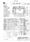
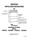
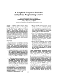
TOSHIBA
I NSTRUCTI O N M A N U A L
CURRENT RELAY
RC803A-HP1
TOSHIEA
CORPORATION
TOSHIBA
6F9E0090
CONTENTS
1.
G e n e r a l Descrigtion __-----_-__----____---------------------
2
2.
C h e c k B e f o r e U s i n g -__-----__-_---_-_______________________-
2
-_-_-_---_-__-__-_----------------
2
2.1
E x t e r n a l Amearance
2.2
Specifications
3.
DescriDtion o f
4.
Applications
-
_--_---_-__-__--_-__-------------------
ODeration__-______-_______-__---------------
__-______-_________----------------------------
3
5
6
4.1
Overcurrent Detection on Hotors -----------------------
6
4.2
Undercurrent Detection on Motors ----------------------
0
b.3
Limiting Starting Current of Rotors -------------------
9
4.4
Transformers
4.5
H e a t e r s , Laape a n d O t h e r C i r c u i t s - - - - - - - - - - - - - - - - - - - - -
-__----__-__-___-___----------------------
---____----___-_-_-_____________________-----------
5.
Mounting
6.
A d j u s t a e n t s - - - - - - - - - - --__-_----______---___________________
10
10
10
12
6.1
Current Setting ____-----_-_____-______________________
12
6.2
S e t t i n g t h e D e t e c t i o n D e l a y Tiae - - - - - - - - - - - - - - - - - - - - - -
12
6.3
S e t t i n g t h e R e s p o n s e D e l a y Tiae - - - - - - - - - - - - - - - - - - - - - - -
13
7.
Ogerat ional l e s t ____--_____--___________________________---
13
8.
C o v e r Reaoval _ - _ - m - m m - - - - _ _ _ _ - _ _ - _ _ - _ _ - - _ _ _ - _ _ _ _ _ _ _ _ _ _ _ _ _ _ _
17
- l-
.
=rosHl=A
6F9E0090
Please thoroughly read this instruction manual
before using the
RC803A Current SensinD Relay.
1. General DescriDtion
This current relay is designed to detect current in AC circuits
with a wide range of aDDiications,
e.t., detection of abnoraai
current of VariOUS electrical eauiment
c i r c u i t s (e.g., heater
circuits),
due to overloads or broken
detection
of
starting
current
to
autoaaticaiiy advance the secondary resistance on induction wound
rotor motor controllers.
During starting, excessive current such as inrush current, lay
exceed rated current flow in motor or transforaer circuits.
this
current relay has an adjustable delay circuit to prevent it fro&
operating during start-up.
F u r t h e r , t h i s c u r r e n t relay i s f a i l s a f e . T h e r e l a y ooerates
-
at the saae tile control Dower is applied. and the relay is deenergized when the inout signal
exceeds the Dreset level or control
Dower is removed.
2. Check Before Using
Before using this relay. check the following Doints. If any
defects are found, contact the dealer free which you purchased this
relay.
2 . 1 E x t e r n a l Aopearance
Check the relay for any missing Darts and for damage, dirt,
rust, and loosened screi6 caused during transportation.
-2-
TOSHIBA
6F9EO090
2.2 Specifications
_____________-_-________________________-----------------------------SPECIFICATIDHS
ITEH
Rated Current
5A (continuous)
Range of current
0.5 - 5A (For current above this range, use a
sensing
CT (current transforrer) and connect the
relay to its secondary side).
Inout c i r c u i t
> low voltage circuit (below AC 6OOV)
voltage
3 To detect current in high voltage circuits,
use a CT, and connect the relay to its
secondary
Type of Current
ReSDOnSe
delay
side.
Overcurrent,
Undercurrent
0.1 - 3s
time-adjustable
range
Detection delay
0.1 - 30s
tile-adjustable
range
Operating volt.
a5 - 132VAC. 170 - 250VAC, 50/6Diiz
i
-
3-
TOSHIEA
6F9E0090
ITEH
A m b i e n t temp.
SPECIFICATIORS
- 1 0 - *SO%
range
Temp. e r r o r
+10X a t
Dielectric with-
Between terminals and ground
stand voltage
Imgulse w i t h stand voltage
Insulation
resistance
t30Y
2DOOVAC f o r 1 #in.
Between terminals and ground
1 X 40)~s a t 45OOV ( s t a n d a r d w a v e f o r m )
B e t w e e n t e r m i n a l s a n d g r o u n d 1DOH Ohm o r
more w h e n m e a s u r e d w i t h a SDOVDC a e g g e r .
-
Vibration
-Oscillation
A m p l i t u d e 2.5~ - 20Hz (26)
-1aoulse
156
Overcurrent
4 0 t i m e s o f m a x . c o n t i n u o u s c u r r e n t (SAI,
intensity
f o r 1 s e c . , agglied t w i c e , i n a c c o r d a n c e w i t h
JEC 174.
Output
contact
rating
Over Current: SPDT
Under Current; SPDT
(250VAC aax. I
- 4-
TOSHIBA
6F9E0090
t-K&WEHA AC
Rating
Designation
B300
120
I
Continuous
5A
SA
(p.f.-0.4)
240
24
240
ITEH
3A
SA
_--_________________-----------------.
0.3A
!iA
O.l!iA (L/R=15ms)
5A
O.lA
5A
SPECIFICATIONS
Hysteresis
Power consumption
Break
AC
DC 120
-
Inductive load
AgDrox. 10X of ooerating value.
oDperating Power 3.5VA
olnput Circuit D.lVA (when 5A is applied)
Height
.75kg ( 1 . 7 lb)
3 . DescriDtion o f Ooeration
When the detected current exceeds the detection circuit
o p e r a t i n g l e v e l , t h e d e t e c t i o n d e l a y t i m e r i s a c t u a t e d . I f overcurrent is continuously detected for more then the detection delay
time set value, the overcurrent response delay timer is actuated.
Then, if overcurrent is detected when the resDonse delay timer has
elapsed, the overcurrent relay is actuated.
If current drops below the undercurrent detection set ValUe,
the resgonse delay timer is actuated, and after the set tile has
exoired,
the undercurrent detection relay is actuated. In the case
of undercurrent detection, the detection delay timer is not actuated.
-5-
TOSHIBA
6F9E0090
Detection delay
.I
.pL1
4
mrellt
level (0.3-O.b5A)
0
\
Undercurrent detect img
FiD. 1 Characteristics
1. APDl ication
4.1 Overcurrent Detection on Hotors
An aDDlication example Is shown in Fig. 2. In this clrcult.
an excessive load is detected by detecting the overcurrent of a
motor and the lain circuit is ooend to Protect
- 6-
TOSHIBA
6F9Eoo90
the uotor
from being damaged.
If the detected current is above
!iA. and in case of a high voltage circuit, use an external CT and
connect the secondary side of CT to the relay as shown in the
following
figure:
AC3-Phase Power SuDDly
Ll
Y
I
#
23
A
1
I
‘I
=
I1
Current relay
Note: T h e RCB03’s OUtDUt
contacts are shown
with Dower source
aDDl ied.
TiD. 2 ADDlication ExaaDle using An External CT
T O S H I B A
6F9E0090
further, when this relay is used in a uotor circuit, the
detection delay timer should be set lonfler
than the startinv
time (about 120%) so that this relay is not actuated by inrush
current.
If current flowinp in the uain circuit becomes
abnormal
after the tiee Deriod of the detection delay timer has elapsed.
the relay is actuated when the set tiue of the response delay
tiler i s o v e r .
4.2 Undercurrent Detection on Hotors
To utilize the undercurrent detection function, the relay
i s u s e d i n a notor c i r c u i t w i t h a f i x e d l o a d , t o d e t e c t l i v h t
or no load conditions.
For examDIe.
in the case of a DUUD UOtOr,
this relay is used to detect undercurrent when the VOlUue Of
water SUDDlied in a water Dipe is low, or in case of a thread
-
winding rachine, when the tension of the thread droes.
TOSHIBA
6F9EOO90
ACJ-Phase Power SUDDIY
Current
relay
Note: The RC803’s outDut
contacts are shown
with Dower source
aDDl ied.
Fig. 3 Application Example
4 . 3 Limiting S t a r t i n o c u r r e n t o f Rotors
Many eotors of uediua and large capacity use a aethod to
s t a r t b y l i m i t i n g s t a r t i n g c u r r e n t . 8y d e t e c t i n o t h e lain
circuit current, this relay can automatically advance the
starting resistance on the secondary side of the motor (in this
case, the knob of the detection delay timar and that of the
resoonse delay timer should be kept at the minimum settings).
-9-
ToSHIEA
6F9EOO90
4 . 4 Transformers
To use this current relay for detecting overcurrent on
transformers. it is necessary to set the detection delay tiler
with the inrush current of transforeer
taken into consideration.
4 . 5 H e a t e r s , LauDs a n d o t h e r C i r c u i t s
This relay can be used to detect the disconnection of
circuits by sensing the existence of current flow.
In other
words, if disconnection occurs, current does not flow and an
undercurrent condition is detected by the relay.
For exaeDle.
this relay can be used to detect the disconnection of heater
circuits on constant temperature
ovens or heatar circuits for
insulators on transmission and distribution facilities In
extremely cold regions.
5. Hount ing
See Fig. 4 for uounting dieensions. Be careful not to use this
relay in the following conditions:
(1) Locations in aebient teeperatures
outside -10 - +SO”C.
(2) Locations subject to high teeDeratUre, steal or dripping water,
(3)
Dusty/dirty
locations,
(4) LOCatiOnS s u b j e c t t o v i b r a t i o n (total a m p l i t u d e 2.5~ o r eore,
20 tiles/m.
or aore) and shock (above 156 in 3 directions).
4
8
z
- lo-
TOSHISA
6F9E0090
50
7
3-$7 Hole
z
Hountino
Fig. 4 Dimensions
B
!3
t.
- ll-
holes
TOSHIBA
GF9EOO90
6 . AdjustDents
6.1 Current setting
(1) When detected current is in a range of 0.5 - 5A:
After confirming that the current value under noraal load
condition is in a range of 0.5 - SA, set the current
adjusting knob to the desired detecting value.
(2) When detected current is above 5A:
Using an external CT (current transformer), properly suited
for the detected Current value, connect the secondary side of
t h e C T t o t h e input terminal o f t h e r e l a y . C a l c u l a t e t h e
secondary current CorresDonding
value, based on the CT ratio.
to the detected current
Then set the current adjusting
Knob to this calculated value.
-
6.2 Setting the detection delay tiae
Setting time varies depending upon each individual aDDlication.
Adjust the detection delay tile according to the following:
(1) Hotor l o a d
TO avoid detection during start-up, set the delay tire to
aDDroxisately 120% of starting tile.
(2) Transformer load
If the inrush current (inrush time varies deDending uDon
caDacity) i s l a r g e , s e t t h e d e l a y tile to approximately
1 2 0 % o f t h i s i n r u s h tile. Genenrally,
If t h e caDacity i s
Wall, inrush time is short and therefore, even when the
adjusting knob is set at the minims
not be any nuisance tripping.
- 12-
position. there should
TOSHIEA
6F9Eoo9o
6.3 Setting the ResDonse delay time
Adjust the set tile according to the ourgose of detection (I.e.
overcurrent or undercurrent).
The set tire for the resoonse
delay varies ger aDDllcation.
Host applications cay not need
any delay tile.
It is aainly used to prevent nuisance trioging
(ride through) by ignoring aoeentary load gliches.
7 . Ooerational l e s t
(1) Check both the control and detection circuits to confirm there
is no eis-wiring.
(2) Check if the current dedtction tiae delay, and resgonse
tiae delay settings are correct.
(3) If the wiring ard settings are correct, energize the control
-
circuit and check if it is the erooer voltage.
-13-
TOSHIBA
6F9E0090
(4) When the Dower source is aDDlied.
the relay is excited and the
OutDut contact’s states are reversed. The relationshiD
between
the input signal end the outDut contacts are shown in Table 2.
Check this relationship during the test.
Table 2
(5) If no Droblea is found when the Dower source is aDDlied.
turn
the rain circuit switch ON and Derforg the following checks:
(a) In the case of a motor load
I f t h e s e t start-up tiae d e l a y i s t o o s h o r t , t h e r e l a y say
be actuated.
In such a case, reset the detection delay tiae
adjusting knob accordingly.
A f t e r t h e s t a r t - u p tiae d e l a y
has exDired. apply current above the set detection value
t o confirm t h a t t h e r e l a y f u n c t i o n s ( a f t e r t h e resoonse
d e l a y tile),
In addition, check that the detection
i n d i c a t i n g lamp l i g h t s a t t h e sale t i m e t h e r e l a y ODerates.
- 14-
TOSHIBA
6F9E0090
(b) When undercurrent or disconnection is detected
At the sale time the lain circuit switch is turned OH, the
starting current and rated current flows, and the relay is
picked UP.
If current drODS
below the undercurrent set point,
the undercurrent State is detected and the relay drops out.
(Refer to Fig. 5)
Caution:
If input signal to this current relay is zero (When StoDDed).
it is not possible to judge if it is undercurrent or in a
disconnected state.
In this case, it is recommended to
have a circuit connecting a normally
oDen auxiliary con-
tact of the Dain circuit switch in series with the alara or
IauD c i r c u i t .
t h i s w i l l D r e v e n t t h e r e l a y f r o r signalling
fault condition during a normal shutdown.
-
- 15-
a
TOSHIBA
6F9E0090
(6) If the relay does not operate in the above test, check if
the current setting is correct or if the ingut signal is
above the set detection value.
If the ingut signal is
correct, check the operation of the relay by gradually
reducing the setting of the current adjusting knob.
relay still does not ooerate. it is defective.
If the
In this case,
please contact the dealer froa which you purchased the relay
or Toshiba.
Power Source -
Detected current
Overcurrent
detect ion I-/ T3
Undercurrant
detect ion
I
Tl: Detection delay tire
T2: Overcurrent detecting resgonse delay tiler
T3: Undercurrent detecting resgonse delay tlaer
Fig. !i Relay Operation
-
16-
TOSHIBA
6F9E0090
8. Cover Reroval
To adjust the current and time settings the cover must be raaoved.
Reaove the cover by amlYing a force in the direction of the arrow
as shown below.
To replace the cover, place the projection of the
cover in the slip out oreventive hole and then insert the bosses
of the cover into the 2 holes at the uooer left and right.
Cover Ak
-
iz
- 17.-
-
TOSHIBA
CORPORATION