1
INSTRUCTION MANUAL
SYSTEM MANAGEMENT AMPLIFIER
VM-2120 (120 W)
VM-2240 (240 W)
REMOTE MICROPHONE
RM-200M
REMOTE MICROPHONE EXTENSION
RM-210
VOICE ANNOUNCEMENT BOARD
EV-200
SURVEILLANCE BOARD
SV-200M
RM-200M
VM-2120
Please follow the instructions in this manual to obtain the optimum results from this unit.
We also recommend that you keep this manual handy for future reference.
TABLE OF CONTENTS
1. SAFETY PRECAUTIONS ..................................................................................... 4
EQUIPMENT OUTLINES
2.
3.
4.
5.
6.
GENERAL DESCRIPTION ................................................................................... 6
FEATURES ............................................................................................................. 6
HANDLING PRECAUTIONS ............................................................................... 7
INSTALLATION PRECAUTIONS ........................................................................ 7
NOMENCLATURE AND FUNCTIONS
6.1. System Management Amplifier VM-2120/-2240 ............................................... 8
6.2. Remote Microphone RM-200M ....................................................................... 12
6.3. Remote Microphone Extension RM-210 ......................................................... 13
7. SYSTEM CONFIGURATIONS
7.1. Remote Microphone/VM Amplifier Configuration
(The Number of Connected Units) .................................................................... 14
7.2. Remote Microphone Operation Panel Function ............................................... 14
7.3. Connection between Remote Microphone and VM Amplifier .......................... 16
7.4. Power Supply from the VM Amplifier to Remote Microphone .......................... 16
OPERATIONS
8. EMERGENCY ("ALERT" AND "EVACUATION") BROADCAST
8.1.
8.2.
8.3.
8.4.
Emergency Broadcast Equipment .................................................................. 18
Keys/Indicators Used for Emergency Broadcast ............................................ 18
Emergency Broadcast Operation (Typical Example) ...................................... 19
Emergency Broadcast Sequence ................................................................... 21
9. BROADCAST OPERATION AT THE AMPLIFIER
9.1. Microphone Announcements (When Operated by Control Input) .................... 22
9.2. Background Music Broadcast .......................................................................... 22
10. REMOTE MICROPHONE GENERAL-PURPOSE BROADCAST
10.1. Operation and Display Sections ..................................................................... 23
10.2. Broadcast Operation ...................................................................................... 24
11. GENERAL-PURPOSE BROADCAST PRIORITY
11.1. Broadcast Source-to-Priority Relationship ..................................................... 27
11.2. Broadcast Priority between Equipment with the Equal Priority Level
11.2.1. Priority mode between equipment with the equal priority level .......... 28
11.2.2. Priority function when 2 broadcasts
with the equal priority level are simultaneously made ....................... 29
11.3. Priority Function during BGM Broadcast ........................................................ 29
12. CHIME FUNCTION
12.1. Available Chime Tone Types
12.1.1. Seven different chime tones .............................................................. 30
12.1.2. Six built-in chimes .............................................................................. 30
12.1.3. Pre-recorded chime ........................................................................... 30
12.2. How the Chime Tone Is Used
12.2.1. Chime tone for Inputs 1 – 3 ................................................................ 30
12.2.2. Telephone paging chime tone ............................................................ 30
12.2.3. Independent chime activation (remote control) .................................. 31
12.2.4. Westminster chime ............................................................................ 32
AMPLIFIER INSTALLATION
13. CHOKE COIL INSTALLATION .......................................................................... 33
14. INPUT TRANSFORMER INSTALLATION AND
ITS BOARD MODIFICATION
14.1. Transformer Installation ................................................................................. 34
14.2. Switching Off the Phantom Power Supply ..................................................... 35
14.3. Instructions When the Sub- and Master VM Amplifiers Are Connected ........ 35
2
15. MOUNTING AN OPTIONAL
EV-200 VOICE ANNOUNCEMENT BOARD ................................................... 36
16. MOUNTING AN OPTIONAL
SV-200M SURVEILLANCE BOARD ................................................................. 38
17. RACK MOUNTING .............................................................................................. 40
AMPLIFIER CONNECTIONS
18. AMPLIFIER INPUT CONNECTION
18.1. Two Amplifiers Stack-Connection .................................................................. 40
18.2. Microphone Connection to the VM Amplifier .................................................. 40
18.3. Telephone Paging Input Connections ............................................................ 41
19. EXTERNAL ATTENUATOR CONTROL WIRING
19.1. 4-Wire System Connection ............................................................................ 42
19.2. 3-Wire System Connection ............................................................................ 43
20. CHANGING THE SPEAKER LINE VOLTAGE ................................................ 44
21. CONTROL I/O CONNECTOR FUNCTIONS .................................................... 45
22. SURVEILLANCE I/O CONNECTOR FUNCTIONS ........................................ 47
SETTINGS
23. FUNCTION SWITCH OPERATION
23.1. VM Amplifier's Rear Panel-Mounted Function Switches ................................ 48
23.2. VM Amplifier's Internal Function Switches ..................................................... 49
23.3. Remote Microphone's Function Switches ...................................................... 50
24. BROADCAST GROUP/ZONE SETTING
24.1. Routing Assignment
24.1.1. Zone-to-Group assignment ................................................................ 51
24.1.2. Control input/Telephone paging
/Westminster chime-to-Group assignment ......................................... 51
24.1.3. Recorded Message-to-Group assignment ......................................... 52
24.2. Operating Keys .............................................................................................. 52
24.3. Zone-to-Group Assignment Operation ........................................................... 53
24.4. Control Input/Telephone Paging
/Westminster Chime-to-Group Assignment Operation ................................... 56
24.5. Recorded Message-to-Group Assignment Operation .................................... 58
REMOTE MICROPHONE INSTALLATION
25. LINKAGE BETWEEN REMOTE MICROPHONE
AND ITS EXTENSION ........................................................................................ 59
MISCELLANEOUS
26. NAME LABEL PREPARATION
26.1. Amplifier's Label Preparation ......................................................................... 60
26.2. Remote Microphone's Label Preparation
26.2.1. Name label type and usable paper .................................................... 60
26.2.2. Preparing the name label ................................................................... 60
26.2.3. Inserting the name label ..................................................................... 60
27. COMPACTFLASH (CF) CARD RECORDING
27.1. Recording ....................................................................................................... 63
27.2. Message Program/Sentence Composition Example ..................................... 63
27.3. Message Program Example ........................................................................... 64
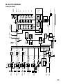
28. BLOCK DIAGRAM .............................................................................................. 65
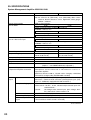
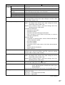
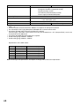
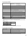
29. SPECIFICATIONS
System Management Amplifier VM-2120/-2240 ..................................................... 66
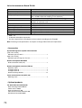
Remote Microphone RM-200M ............................................................................... 69
Remote Microphone Extension RM-210 ................................................................. 69
Voice Announcement Board EV-200 ...................................................................... 70
Accessories ............................................................................................................. 70
Optional products .................................................................................................... 70
3
1. SAFETY PRECAUTIONS
• Be sure to read the instructions in this section carefully before use.
• Make sure to observe the instructions in this manual as the conventions of safety symbols and messages
regarded as very important precautions are included.
• We also recommend you keep this instruction manual handy for future reference.
Safety Symbol and Message Conventions
Safety symbols and messages described below are used in this manual to prevent bodily injury and property
damage which could result from mishandling. Before operating your product, read this manual first and
understand the safety symbols and messages so you are thoroughly aware of the potential safety hazards.
WARNING
Indicates a potentially hazardous situation which, if mishandled, could
result in death or serious personal injury.
CAUTION
Indicates a potentially hazardous situation which, if mishandled, could
result in moderate or minor personal injury, and/or property damage.
WARNING
When Installing the Unit
[Applicable to all models]
• Do not expose the unit to rain or an environment
where it may be splashed by water or other liquids,
as doing so may result in fire or electric shock.
• Use the unit only with the voltage specified on the
unit. Using a voltage higher than that which is
specified may result in fire or electric shock.
• Avoid installing or mounting the unit in unstable
locations, such as on a rickety table or a slanted
surface. Doing so may result in the unit falling
down and causing personal injury and/or property
damage.
[Applicable to the VM-2120/-2240]
• Do not cut, kink, otherwise damage nor modify the
power supply cord. In addition, avoid using the
power cord in close proximity to heaters, and never
place heavy objects – including the unit itself – on
the power cord, as doing so may result in fire or
electric shock.
[Applicable to the RM-200M/-210]
• Install the unit only in a location that can
structurally support the weight of the unit and the
mounting bracket. Doing otherwise may result in
the unit falling down and causing personal injury
and/or property damage.
4
• Do not use other methods than specified to mount
the bracket. Extreme force is applied to the unit
and the unit could fall off, possibly resulting in
personal injuries.
• Use nuts and bolts that are appropriate for the
ceiling's or wall's structure and composition. Failure
to do so may cause the unit to fall, resulting in
material damage and possible personal injury.
When the Unit is in Use
[Applicable to all models]
• To prevent a fire or electric shock, never open nor
remove the unit case as there are high voltage
components inside the unit. Refer all servicing to
your nearest TOA dealer.
• Do not place cups, bowls, or other containers of
liquid or metallic objects on top of the unit. If they
accidentally spill into the unit, this may cause a fire
or electric shock.
• Do not insert metallic objects such as pointed
objects and coins, or flammable materials in the
unit's openings, as this may result in fire or electric
shock.
• Do not touch a plug during thunder and lightning,
as this may result in electric shock.
[Applicable to the VM-2120/-2240]
• Should the following irregularity be found during
use, immediately switch off the power, disconnect
the power supply plug from the AC outlet and
contact your nearest TOA dealer. Make no further
attempt to operate the unit in this condition as this
may cause fire or electric shock.
· If you detect smoke or a strange smell coming
from the unit.
· If water or any metallic object gets into the unit
· If the unit falls, or the unit case breaks
· If the power supply cord is damaged (exposure of
the core, disconnection, etc.)
· If it is malfunctioning (no tone sounds.)
CAUTION
When Installing the Unit
[Applicable to all models]
• Avoid installing the unit in humid or dusty locations,
in locations exposed to the direct sunlight, near the
heaters, or in locations generating sooty smoke or
steam as doing otherwise may result in fire or
electric shock.
[Applicable to the VM-2120/-2240]
• Never plug in nor remove the power supply plug
with wet hands, as doing so may cause electric
shock.
• When unplugging the power supply cord, be sure
to grasp the power supply plug; never pull on the
cord itself. Operating the unit with a damaged
power supply cord may cause a fire or electric
shock.
• Do not block the ventilation slots in the unit's cover.
Doing so may cause heat to build up inside the unit
and result in fire.
When the Unit is in Use
[Applicable to all models]
• Do not place heavy objects on the unit as this may
cause it to fall or break which may result in
personal injury and/or property damage. In
addition, the object itself may fall off and cause
injury and/or damage.
[Applicable to the VM-2120/-2240]
• Make sure that the volume control is set to
minimum position before power is switched on.
Loud noise produced at high volume when power is
switched on can impair hearing.
• Do not operate the unit for an extended period of
time with the sound distorting. This is an indication
of a malfunction, which in turn can cause heat to
generate and result in a fire.
• Contact your TOA dealer as to the cleaning. If dust
is allowed to accumulate in the unit over a long
period of time, a fire or damage to the unit may
result.
• If dust accumulates on the power supply plug or in
the wall AC outlet, a fire may result. Clean it
periodically. In addition, insert the plug in the wall
outlet securely.
• Switch off the power, and unplug the power supply
plug from the AC outlet for safety purposes when
cleaning or leaving the unit unused for 10 days or
more. Doing otherwise may cause a fire or electric
shock.
• When moving the unit, be sure to remove its power
supply cord from the wall outlet. Moving the unit
with the power cord connected to the outlet may
cause damage to the power cord, resulting in fire or
electric shock. When removing the power cord, be
sure to hold its plug to pull.
[Applicable to the VM-2120/-2240]
An all-pole mains switch with a contact separation of at least 3 mm in each pole shall be incorporated in
the electrical installation of the building.
[Applicable to the VM-2120/-2240 and RM-200M]
The socket-outlet shall be installed near the equipment and the plug (disconnecting device) shall be
easily accessible.
5
2. GENERAL DESCRIPTION
[System Management Amplifier VM-2120/VM-2240]
Featuring outstanding audio performance, the TOA System Management Amplifier VM-2120/-2240 satisfies
the growing need for reliable and efficient communications for various applications, especially for mediumsized facilities including office building, factories, hospitals, and transportation terminals.
The VM-2120 (120 W) and VM-2240 (240 W) are multifunctional amplifiers that can be mounted in an EIAStandard equipment rack (3-unit size). Both units come with 4 audio inputs including the background music
input, and the speaker output section which has an internal attenuator and 5-zone selector. They permit not
only general-purpose broadcast, but also Emergency Broadcast based on the EN60849 Standard which gives
pre-recorded voice instructions*1 in the emergency situation. Broadcast can be made from an optional RM200M Remote Microphone as well as from the amplifier, and can be remotely controlled from external
equipment. In addition, both amplifiers feature the surveillance function*2 which automatically checks the
system for failures.
*1 An optional EV-200 Voice Announcement Board is required.
*2 An optional SV-200M Surveillance Board is required.
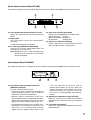
[Remote Microphone RM-200M]
The RM-200M is a dedicated unit for both the VM-2120 and VM-2240, and permits Emergency Broadcast as
well as general-purpose broadcast.
[Remote Microphone Extension RM-210]
The RM-210 is an extension unit for the RM-200M's key operating section.
3. FEATURES
• Broadcasts of up to 480 W can be made to up to 10 zones individually or simultaneously.
(when 2 VM-2240's are used).
• Permits monitoring of individual speaker line or power amplifier failures for status indication.
(Requires the optional SV-200M Surveillance Board.)
• Reproduces 5 general-purpose messages, 1 chime tone, and 2 emergency messages.
(Recordable as you like using the optional EV-200 Voice Announcement Board)
• Six different built-in chimes and prerecorded chime tones (by the EV-200) can be selected to attract
attention to broadcasts.
• Backup battery maintains operation during power failures.
• Emergency broadcast based on the EN60849 Standard provides prerecorded voice instructions in the
emergency situation.
• Emergency broadcast bypasses both the amplifier volume control and the external attenuator, making sure
that the broadcast is heard throughout all zones.
• Features following broadcast priority levels: the highest level for Emergency broadcasts and 4 levels for
general-purpose broadcasts.
• Speaker lines for 100 V line applications (standard) or for 50 V or 70 V line applications (enabled by
changing the unit's internal wiring).
• Up to 4 remote microphones can be connected, and their total connection cables can be extended to 800 m.
(RM-200M/-210)
• Speaker zones can be programmed into up to 5 groups for group broadcast.
(The remote microphone can broadcast to the Groups 1 and 2 out of the 5 groups.)
• Clear, distortion-free announcements owing to the internal compressor circuitry. (RM-200M/-210)
6
4. HANDLING PRECAUTIONS
[VM-2120/VM-2240 and RM-200M/RM-210]
To clean, be sure to first switch off the power supply to the unit, then wipe with a dry cloth. When the unit gets
very dirty, use a cloth damped in a neutral cleanser. Never use benzene, thinner or chemically-treated
cleaning cloth because such volatile liquids could deform or discolor the unit.
[VM-2120/VM-2240]
• When the EV-200 is mounted, never move the unit from one place to another with the Flash Card inserted
because the EV-200 or the CompactFlash card may fail.
• Avoid inserting or withdrawing the CompactFlash card while the unit is alive.
5. INSTALLATION PRECAUTIONS
[VM-2120/VM-2240 and RM-200M/RM-210]
• Do not install the unit in locations exposed to the direct sunlight or heaters, as the unit could be deformed or
discolored.
• Avoid installing or storing the unit in dusty or humid locations, as doing otherwise could cause the unit's
failure.
• Keep the unit as far away as possible from a fluorescent lamp, digital equipment, PC or other equipment
which generate high frequency noise.
[VM-2120/VM-2240]
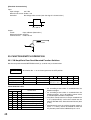
• Do not block the ventilation slots on the upper, right and left, and rear sides to allow inside heat radiation.
• Keep at least 50 mm space from the unit's right and left sides for heat radiation.
Amplifier
(VM-2120/-2240)
At least 50 mm
At least 50 mm
• Never connect the AC power cord to any other line voltage than that specifically designated.
• To avoid oscillation, keep the input cable away from the output cable. Particular care must be exercised
when mounting the unit in an equipment rack.
• In some installations, a ground loop is formed and hum noise may be generated. In such cases, connecting
the rear-mounted signal earth terminal to the body of connected equipment (BGM sound source, expansion
amplifier, etc.) may reduce it.
• Never connect two amplifier outputs in parallel under any circumstances.
Caution
• When such work as mounting optional boards or setting switches needs to open the amplifier's top
cover, leave it to a qualified service technician.
• In the case above, be sure to switch the power off before the work.
• A warning that TERMINALS marked with the symbol
are HAZARDOUS LIVE and that the
external wiring connected to these TERMINALS requires installation by an INSTRUCTED PERSON
or the use of ready-made leads or cords.
7
6. NOMENCLATURE AND FUNCTIONS
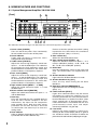
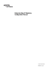
6.1. System Management Amplifier VM-2120/-2240
[Front]
8
9
12
3
16
4
15
2
5
1
11
6 7 10
11
13
14
The VM-2120 is shown in the figure. The VM-2240 is the same in both appearance and function.
1. Power switch [POWER]
Turns on and off the power. Press continuously
for 0.3 second or more to turn off the power.
2. Power indicator
Lights when the power is turned on, and is
extinguished when turned off.
3. Treble control [TREBLE]
Adjusts the level of high frequency sound from
Inputs 1 – 3 and the BGM Input. Turn clockwise
to accentuate the high frequency output and
counterclockwise to attenuate it. The center click
position indicates a flat frequency response.
4. Bass control [BASS]
Adjusts the level of low frequency sound from
Inputs 1 – 3 and the BGM Input. Turn clockwise
to accentuate the low frequency output and
counterclockwise to attenuate it. The center click
position indicates a flat frequency response.
5. Input volume control [INPUT 1 – 3, BGM]
Adjusts the sound volume for Inputs 1 – 3 and
the BGM Input.
6. Master volume control [MASTER]
Adjusts the mixed sound volume for Inputs 1 – 3
and the BGM Input.
7. Reset key
Press this recessed key with a pointed object to
reset the unit's internal computer if the unit
malfunctions, key inputs are not accepted or
other troubles occur. Note that other preset
parameters are not reset. This key is also used
in combination with other keys to enter the
setting mode.
8. Zone indicator
Lights to indicate the broadcast zone (Zones 1 –
5) selected with the Zone Selector key.
8
Flashes to show the speaker zone which is being
inspected or has failed when the surveillance
function operates. (See p. 11 No. 41.)
9. Zone selector key
Selects the desired broadcast zone.
10. Zone volume control [ZONE 1 – 5]
Adjusts the broadcast volume for Zones 1 – 5 in
6 steps: 0 dB (Max. position), –3 dB, –6 dB, –10
dB, –15 dB, and –20 dB (Min. position).
11. Name label
Used for indicating the name of each input and
zone. (The blank labels are supplied with the
unit.)
12. All-zone broadcast indicator
Lights when the All-Zone Broadcast is made.
13. All-zone broadcast key [ALL]
Press this key when making the All-Zone
Broadcast.
14. Emergency indicator [EMERGENCY]
Lights when the unit is in Emergency mode.
(See p. 21.)
15. Failure indicator [FAULT]
Lights when communications with the remote
microphone or expansion amplifier are not
correctly performed, the Voice Announcement
board malfunctions, or speaker line failure (short
circuit, ground fault, or disconnection) occurs.
Failure information is transmitted from the rear
panel-mounted control input and output
connector [CONTROL I/O] (No. 30).
16. Level meter
Indicates the power amplifier's output level,
reaching "0 dB" at rated output (100 V). In general
use, broadcast volume should be set below the
point where the red indicator (0 dB) begins to light.
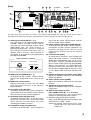
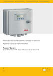
[Rear]
32
22
20
18
SV-200M
EV-200
33
34
17
24
31
35
23
21
30 19
29
28
27 26 25
The figure above shows the 230 V AC versions of the VM-2120 and VM-2240. The 120 V AC versions are the same in
both appearance and function except the rating indications of the AC inlet (No. 33) and fuse holder (No. 34).
17. Audio input terminal [INPUT 1, 2, 3]
The input level can be switched between MIC
(–60 dB*1, 600 Ω) and LINE (–10 dB*1, 600 Ω)
using the rear panel-mounted function switch
[SETTINGS] (No. 29). Each terminal is
electronically balanced*2, and has a combined
XLR (female) connector and phone jack. In
addition, Input 1 features a DIN connector for
connection of an optional Paging Microphone
VR-1001B or PM-660D.
Usable connectors and plugs
• XLR type male connector
• Phone plug
Sleeve: Ground
Pin 1: Ground Pin 2: Hot
Pin 3: Cold
Ring: Cold Tip: Hot
18. BGM input jack [BGM INPUT 1, 2]
An RCA pin jack with –20 dB*1, 10 kΩ, monaural.
Connect the background music source to this
jack.
19. BGM input volume control
Adjusts the broadcast volume for each BGM
input. The volume increases as the control is
turned clockwise.
20. Line output jack [LINE OUT]
An RCA pin jack with 0 dB*1, 10 kΩ. Outputs the
signal before the master volume control. Connect
this jack to the line input of other equipment.
21. Recording output jack [REC OUT]
An RCA pin jack with 0 dB*1, 10 kΩ. This jack is
connected in parallel to the line output [LINE
OUT]. Connect a cassette deck, etc. when
recording the broadcast contents.
22. Preamplifier output jack [PRE OUT]
An RCA pin jack with 0 dB*1, 10 kΩ. Outputs the
signal after the master volume control. Connect
this jack to other power amplifier.
23. Power amplifier input jack [POWER AMP IN]
An RCA pin jack with 0 dB*1, 10 kΩ. Connect a
preamplifier or other external equipment. By
inserting a pin plug into this jack, the sound
source can be switched over to the external
equipment.
24. Link connector [LINK]
An RJ45 female connector. Links another VM
(VM-2120/-2240) amplifier* 3 or optional RM200M Remote Microphone units (up to 4 units
per system). Features electronically balanced*2
input to accept audio signals from the RM-200M.
When 2 VM amplifiers are stack-connected,
connect the master unit's "PRE OUT" (No. 22) to
the sub-unit's "POWER AMP IN" (No. 23) as well
as the LINK-to-LINK connection between both
units.
25. Remote microphone input volume control [RM]
Adjusts the broadcast volume for the connected
remote microphone.
26. Chime volume control [CHIME]
Adjusts the broadcast volume for the unit's builtin chime.
27. Telephone paging volume control
Adjusts the broadcast volume for the Telephone
Paging Input.
28. External connection terminal
[TEL PAGING, CTRL IN 1, 2, 3, 24 V OUT]
A push-in terminal block. This terminal block
features the following connection sections.
(1) Telephone paging input [TEL PAGING]
Voice sound: Electronically-balanced input*2 with
shield terminal, –10 dB*1, 10 kΩ.
Control: No-voltage make contact input, open
voltage: 30 V DC, short-circuit current:
under 0.1 A
9
(2) Control input for broadcast activation
[CTRL IN 1, 2, 3]
3 no-voltage make contact inputs, open voltage:
3.3 V DC, short-circuit current: under 1 mA
(3) 24 V DC Power output [24 V OUT]
Supplies the 24 V DC/0.2 A power to an optional
Amplifier Control Unit RU-2001/-2002.
29. Function switch [SETTINGS]
An 8-bit DIP switch and selects
(1) Phantom power on-off for each input 1 – 3
(2) Telephone paging chime on-off
(3) 7 different types of chime tones [2-tone chime/2tone chime (fast repeat)/4-tone chime (Up)/Singletone chime/4-tone chime (Up & Down)/Gong, and
Pre-recorded chime*4], or chime-off
(4) MIC/LINE gain for inputs 1 – 3
Refer to page 48 "FUNCTION SWITCH
OPERATION" for operation of the function
switch.
30. Control input and output connector
[CONTROL I/O]
A 25-pin, female D-sub connector.
(1) External control input
The following functions can be activated from
external equipment.
• Message for an optional Voice Announcement
Board
• Chime
• Power
• Emergency Broadcast
• Unit's broadcast cutoff
(2) Status output
When the unit is placed in the following status,
the corresponding output is at make.
• Irregularity of communications with the Remote
Microphone and an expansion amplifier.
• AC power ON
• DC power ON
• Irregularity of the sound source of the Voice
Announcement Board.
• Failure (FAULT) indication on
• Power switch on
31. Attenuator control, external speaker input,
speaker output connector
[ATTENUATOR CONTROL, EXTERNAL SP
INPUT, DIRECT OUT, ZONE 1 – 5]
A dedicated, 16-pin plug-in screw connector and
has the following input and outputs.
(1) External attenuator control output
[ATTENUATOR CONTROL]
An output terminal for bypassing the external
attenuator.
10
(2) External speaker line Input
[EXTERNAL SP INPUT]
Accepts the signal from the external amplifier's
speaker line. When the unit's broadcast cutoff
input terminal of the Control Input and Output
Connector (No. 30) is activated by an emergency
equipment, the unit's power amplifier output is
cut off, allowing the external signal to go through
to the speakers in all zones.
(3) Direct speaker line output [DIRECT OUT]
Outputs the signal directly from the power
amplifier transformer output.*5 The volume level
is the same as that which can be provided when
the Zone Volume Control (No. 10) is set to the
maximum position.
(4) Speaker output [SP OUT, ZONE 1 – 5]
Connects to the speaker lines. This output is of
100 V line type, but can be converted to the 50 V
or 70 V line type by internal connection change.
32. 24 V DC power input
Connect the backup battery (maximum 24 V
DC/7.5 A for VM-2120, 15 A for VM-2240) to this
terminal.
33. AC inlet [AC mains]
Connect the supplied power cord to this inlet.
34. Fuse holder
The following miniature fuses (20 mm type) are
used.
6.3 A (for 120 V AC version)
T2.5 A of time lag type (for VM-2120 230 V AC
version), T3.15 A of time lag type (for VM-2240
230 V AC version)
Note: When the fuse is blown off, first remove
the cause, then replace with the correct
type specified on the unit.
35. Signal earth terminal
Note this terminal is not a safety earth. When
there is hum noise, connecting this terminal to
the body of connected equipment (BGM sound
source, expansion amplifier, etc.) may reduce it.
*1 0 dB = 1 V
*2 Can be transformer-balanced with the addition
of an optional IT-450 input transformer.
*3 Both the VM-2120 and the VM-2240 can also
be combined.
4
* The chime sound source must be prerecorded into a CF (CompactFlash) card to be
inserted into the optional EV-200 Voice
Announcement Board. (See p. 11.)
5
* Output signal source is switched to the
EXTERNAL SP INPUT if the unit's broadcast
cutoff is activated. See No. 31 (2).
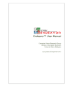
[Voice Announcement Board EV-200]
The following functions No. 36 through No. 40 are used when an optional EV-200 Board is mounted in the unit.
39
37
40
38
36. Voice Announcement board volume control
Adjusts the volume for the Voice Announcement
Board.
37. Eject button
Press this button to eject the CompactFlash*
(CF) Card.
* Trademark of SanDisk Corporation
38. CF card slot [COMPACTFLASH CARD]
Insert the CF Card, the Pre-recorded chime and
message source, into this slot.
Note: Withdrawing the CF card during Message
Broadcast will terminate the broadcast
without completion.
36
39. CPU status indicator [CPU RUN]
Indicates the EV-200 Board's operation status.
Normal operation: Flashes.
Abnormal operation: Steadily on.
No operation:
Extinguished.
40. Card access indicator [ACCESS]
Flashes when the unit is accessing the CF Card,
and is steadily on when a failure occurs.
[Surveillance Board SV-200M]
The following functions No. 41 through No. 43 are used when an optional SV-200M Board is mounted in the unit.
41
41. Surveillance input and output connector
[SURVEILLANCE I/O]
A 25-pin, female D-sub connector.
• Features an input to activate the Surveillance
(failure detection) function, and an output to
indicate the result of failure detection.
• Monitors failures of operations of the unit's
power amplifier section, and ground fault of the
speaker line, then outputs the result of monitor
lighting the Failure Indicator [FAULT] (No. 15).
• The Surveillance function for the speaker line is
performed by suspending a broadcast only
when the unit is activated from external
equipment or the board's internal timer. In this
42
43
case, the indicators of all zones flash to
indicate the broadcast is in pause. When the
speaker line short is determined, the Failure
Indicator [FAULT] (No. 15) lights and at the
same time, the corresponding zone indicator
flashes.
42. Speaker line impedance setting key [SET]
Measures and sets each speaker line reference
impedance value. (reference value for surveillance
criteria)
43. Line check key [CHECK]
Checks each speaker line impedance for the line
failure detection.
11
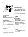
6.2. Remote Microphone RM-200M
[Top]
2
2
1
11
12
3
4 5
10. All-zone broadcast key (ALL-ZONE)
Press this key to make the All-Zone Broadcast.
13
11. Zone selector key (ZONE 1 – 5)
Selects the desired broadcast zones (Zones 1 – 5).
6
14
7
8
9
10
15 16
17
1. Gooseneck microphone
A unidirectional microphone.
2. Name label
Insert the label (not thicker than 0.2 mm) indicating
the name of each panel control and indicator. (See
p. 60 "NAME LABEL PREPARATION.")
3. Power indicator (POWER)
Lights green when the power is supplied to the
unit.
4. Failure indicator (FAULT)
Lights yellow when the VM (VM-2120/-2240)
amplifier's front panel-mounted failure indicator
lights.
Flashes yellow when a communications failure
occurs between the unit and the VM amplifier.
5. Emergency indicator (EMERGENCY)
Lights red when the VM amplifier is in Emergency
mode. (See p. 21.)
6. Emergency broadcast switch (EMERGENCY)
Press this switch after opening the security cover
when making the Emergency Broadcast.
7. Groups 1&2 indicator (GROUP 1, 2)
Lights green when the corresponding group is
selected with the key.
8. Groups 1&2 broadcast key (GROUP 1, 2)
Press this key to make the Group Broadcast
(Broadcast to preprogrammed multiple zones).
(See p. 51 "BROADCAST GROUP/ZONE
SETTING.")
9. All-zone indicator (ALL-ZONE)
Lights green when the All-Zone Broadcast is
selected with the key.
12
12. Zone indicator (ZONE 1 – 5)
Lights green when the corresponding broadcast
zone (Zones 1 – 5) is selected.
13. Message (MESSAGE 1 – 5)/zone (ZONE 6 –
10) selector key
(1) When only a single VM-2120 or VM-2240
amplifier is connected
Selects broadcast messages 1 – 5 pre-recorded
on the optional Voice Announcement Board EV200.
(2) When two VM-2120 or VM-2240 amplifiers are
connected
Selects broadcast zones 6 – 10.
14. Message (MESSAGE 1 – 5)/zone (ZONE 6 –
10) indicator
Lights green when the corresponding Message
(Zone) Selector Key is pressed.
15. Busy indicator (BUSY)
Flashes orange or green when other connected
sound source unit is in use.
Orange: The RM-200M cannot operate.
Green: The RM-200M can interrupt the busy
unit.
16. In-use indicator (IN-USE)
Lights green when the RM-200M is in use.
17. Talk key (TALK)
Either of the following two operating methods can
be selected. (See p.50 "Remote Microphone's
Function Switches.")
(1) Press-to-talk system
Announcements can be made from the
microphone while the key is pressed, and are
terminated when released.
(2) Talk lock system
One-touch depression locks the key and permits
announcements to be made from the
microphone. Press the key again to terminate the
announcement.
Note
In the Emergency Broadcast, the Talk key
operates in the "press-to-talk" system even if set
to the "Talk lock system."
[Rear]
[Right Side]
1
19
18
20 21
18. DC power input jack [DC POWER IN]
• A jack with non-polarity. Connect the 24-V DC
power (AC adapter). (See the specifications on
p. 69.)
• The VM amplifier can supply the power to only
a single Remote Microphone.
(Line resistance: within 24 Ω/one way)
19. Link connector [LINK]
A female RJ45 connector. Connects the VM
amplifier or other RM-200M units (up to 4 units
connectable per system) using the cable of
Category 5 STP straight type.
20. Microphone volume control [MIC]
Adjusts the volume of the unit's gooseneck
microphone or the external microphone input
(No. 21).
23
22
21. External microphone input jack
[EXTERNAL MIC IN]
A 3.5 mm-diameter Mini-jack. Connects a
electronic condenser microphone (ex. headset).
Inserting a Mini-plug switches the microphone
sound source to that which is connected to this
jack.
22. Extension connector [EXTENSION]
Connects the RM-210 Remote Microphone
Extension using the cable supplied to the RM-210.
23.Function setting switch
Used for setting the Remote Microphone's Unit
numbers (1 – 4) and functions as shown in the
"Function Setting table" below.
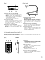
6.3. Remote Microphone Extension RM-210
The RM-210 is used to select the optional EV-200 Voice Announcement Board's voice message when
connecting 2 VM-2120 or VM-2240 amplifiers.
[Top]
[Left Side]
1
2
3
4
1. Name label
Insert the label (not thicker than 0.2 mm) indicating
the name of each panel control and indicator. (See
p. 60 "NAME LABEL PREPARATION.")
2. Message indicator
Lights green when the corresponding Message
Selector Key (1 – 5) is pressed.
3. Message selector key
Selects the broadcast message (1 – 5).
4. Extension connector [EXTENSION]
Connects to the RM-200M Remote Microphone
using the supplied cable.
13
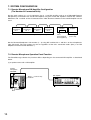
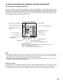
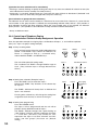
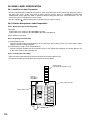
7. SYSTEM CONFIGURATION
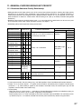
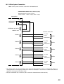
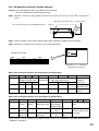
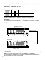
7.1. Remote Microphone/VM Amplifier Configuration
(The Number of Connected Units)
Set the total number (0 – 5) of equipment (up to 1 sub-VM amplifier and up to 4 RM-200M Remote
Microphones) connected to the master VM amplifier using the master VM amplifier's internal DIP switches
SW3-No. 6, No. 7 and No. 8 "No. of connected units." Note that these switches in the sub-VM amplifier are not
used.
Remote
microphone
No. 1
Remote
microphone
No. 2
Remote
microphone
No. 3
Remote
microphone
No. 4
The number of Remote Microphones (0 – 4 units)
Master VM
amplifier
EV-200
Sub-VM
amplifier
Voice
Sub-VM amplifier
announcement
(0 or 1 unit)
board (optional)
Set the Remote Microphone's Unit number (1 – 4) using DIP switches No. 1 and No. 2 on the microphone's
right side panel. The Unit number may be set regardless of the unit's connection order. (See p. 49 "VM
Amplifier's Internal Function Switches.")
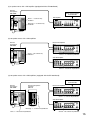
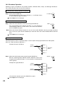
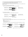
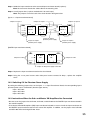
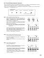
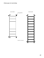
7.2. Remote Microphone Operation Panel Function
The Zone/Message selector key function differs depending on the connected VM amplifier as described
below.
(1) 5 speaker zones with 1 VM amplifier
Remote
microphone
RM-200M
Zone 1 – 5 selector key
/indicator
14
VM amplifier
(2) 5 speaker zones with 1 VM amplifier (equipped with the EV-200 Board)
Remote
microphone
RM-200M
Voice announcement
board EV-200
Zone 1 – 5 selector key
/indicator
VM amplifier
Message 1 – 5 selector key
/indicator
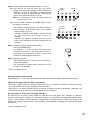
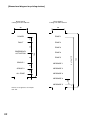
(3) 10 speaker zones with 2 VM amplifiers
Master VM amplifier
Remote
microphone
RM-200M
Zone 1 – 10 selector key
/indicator
Zone 1 – 5 selector key/indicator
Sub-VM amplifier
Zone 6 – 10 selector key/indicator
(4) 10 speaker zones with 2 VM amplifiers (equipped with the EV-200 Board)
Voice announcement
board EV-200
Remote
microphone
RM-200M
Remote microphone
extention
RM-210
Master VM amplifier
Zone 1 – 5 selector key/indicator
Sub-VM amplifier
Message 1 – 5 selector key/indicator
Zone 1 – 10 selector key/indicator
Zone 6 – 10 selector key/indicator
15
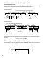
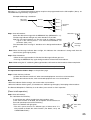
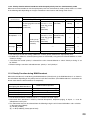
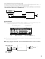
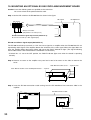
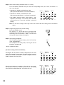
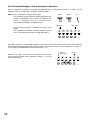
7.3. Connection between Remote Microphone and VM Amplifier
[Connection method vs. Distance]
Using the specified cable, connect between the VM amplifier(s) and Remote Microphone(s) via their LINK
connectors. They can be connected in any order. (Two connection examples are shown.)
Connection example 1
LINK connector (RJ45)
Category 5 STP straight cable*
a
b
c
Remote
microphone
Remote
microphone
Remote
microphone
24 V DC
Power
supply
24 V DC
Power
supply
24 V DC
Power
supply
d
e
Sub-VM
amplifier
Master VM
amplifier
Remote
microphone
PRE OUT jack
POWER AMP IN jack
Audio cable
Connection example 2
Category 5 STP straight cable*
a
Remote
microphone
LINK connector (RJ45)
b
Remote
microphone
24 V DC
Power
supply
c
e
Sub-VM
amplifier
Remote
microphone
Remote
microphone
POWER AMP IN jack
24 V DC
Power
supply
24 V DC
Power
supply
Master VM
amplifier
PRE OUT jack
d
Audio cable
* TIA/EIA-568A standard Category 5 Shielded Twisted-Pair cable (straight type)
Abbreviated to "Cat. 5 STP cable."
The total length of LINK-to-LINK connection cables must be under 800 m (when connected using Category 5
STP cable).
a+b+c+d+e
800 m
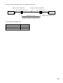
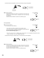
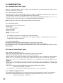
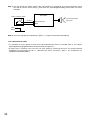
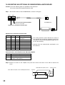
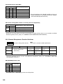
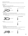
7.4. Power Supply from the VM Amplifier to Remote Microphone
The VM amplifier can only supply power to one Remote Microphone. Therefore, each of the remaining
Remote Microphone(s) needs to have a 24 V DC power supply (AC adapter) of its own.
(1) Power supply via Category 5 STP cable
Category 5 STP straight cable
Remote
microphone
VM amplifier
Up to 800 m via Category 5 STP cable
Category 5 STP cable: 93.8 Ω/km or less
16
(2) Power supply using cables other than Category 5 STP cable
Category 5 STP straight cable
4-pair twisted pair shielded cable
Wall connector (RJ45)
Wall connector (RJ45)
Remote
microphone
VM amplifier
Under 40 Ω (one way)
Category 5 STP straight cable
Example: Up to 200 m via 200 Ω/km cable
4-pair twisted pair shielded cable
Cable resistance (one way)
200 Ω/km
100 Ω/km
50 Ω/km
Extension length
Up to 200 m
Up to 400 m
Up to 800 m
17
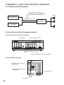
8. EMERGENCY ("ALERT" AND "EVACUATION") BROADCAST
8.1. Emergency Broadcast Equipment
Emergency alert activation input
Emergency evacuation activation input
Emergency stop activation input
External equipment
(ex. fire alarm system)
CONTROL I/O connector
VM amplifier
(VM-2120/-2240)
LINK connector
Remote microphone
(RM-200M)
8.2. Keys/Indicators Used for Emergency Broadcast
System management amplifier VM-2120/-2240
Zone indicator
All zone broadcast indicator
All-zone broadcast key
[ALL]
Emergency broadcast indicator [EMERGENCY]
Remote microphone RM-200M
Emergency broadcast indicator
(EMERGENCY)
Emergency broadcast switch
(EMERGENCY)
Talk key (TALK)
Microphone
18
Speaker
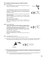
8.3. Emergency Broadcast Operation (Typical Example)
Step 1. Alert Broadcast
Open the RM-200 Remote Microphone's Emergency broadcast
switch cover, and press the switch.
EMERGENCY
A pre-recorded Alert signal tone and Alert announcement will be
alternately broadcast to the entire zone for the preset number of
repetitions.*1 The EMERGENCY indicators of the RM-200M and the
VM amplifier come on.
Alert (or Evacuation) broadcasts terminate all current generalpurpose broadcasts.
(The Alert broadcast is also enabled when the Emergency Alert
input*2 is activated by the fire alarm system or other connected
external equipment.)
Alert
signal
and
message
[Alert announcement example*3]
[Alert signal] Attention please. The fire alarm is indicating a fire.
We're now investigating the cause. Please wait for further
information.
Step 2. Evacuation Broadcast
After the Alert broadcast has been repeated as pre-programmed, it
automatically switches to the Evacuation broadcast, with an
Evacuation signal tone and a pre-recorded Evacuation
announcement alternately broadcast to the entire zone.*1
(The Evacuation broadcast is also enabled when the Emergency
Evacuation input*2 is activated by the fire alarm system or other
connected external equipment.)
Evacuation
signal
and
message
[Evacuation announcement example*4]
[Evacuation signal] There is a fire. Please evacuate as quick as
possible.
Step 3. Live Microphone Announcement
(This announcement can be made during either Step 1 or Step 2.)
3-1. Holding down the Remote Microphone Talk key interrupts the current Emergency broadcast (Alert or
Evacuation broadcast), permitting broadcast of live microphone announcements to the entire zone.
Live microphone
announcements
TALK key
3-2. The microphone announcement is terminated when the Talk key is released, and operation reverts to
the Evacuation broadcast regardless of whether the microphone announcement was made during an
Alert or Evacuation broadcast.*5
Note: In the Emergency Broadcast, the Talk key operates in the "press-to-talk" method regardless of
its operation setting (by the RM-200M's function setting switch No. 4).
19
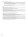
Step 4. Emergency Broadcast Termination
To terminate the Emergency broadcast, activate the Emergency Stop input by way of the
corresponding connected external equipment. The unit returns to the general-purpose broadcast
mode it was in immediately before the Emergency broadcast was started. Then, both EMERGENCY
indicators of the RM-200M and the VM amplifier go out.
Note, however, that the unit does not return to the original general-purpose broadcast depending on
the type of general-purpose broadcast. (See p. 21.)
Notes
• Emergency broadcasts are always made at the maximum volume level. The master and zone volume
controls cannot be used during Emergency broadcast.
• Emergency broadcast cannot be terminated by the Remote Microphone.
• If emergency broadcast is stopped using the Reset key, the unit could not return to the mode it was last in
before the emergency broadcast was activated.
• When the unit not equipped with the EV-200 is placed in emergency broadcast mode, announcements from
the Remote Microphone can be broadcast over the entire area (by bypassing the attenuator). Press the
Remote Microphone's talk switch to make the announcement.
*1 Requires installation of the optional EV-200 Voice Announcement Board.
*2 A terminal built in the rear-mounted CONTROL I/O connector
*3 Requires recording of the Alert signal, broadcast message, and their number of repetitions on an installed
CompactFlash (CF) card. (Consult the dealer from whom the unit was purchased.)
4
* Requires recording of the Evacuation signal and broadcast message on an installed CompactFlash (CF)
card. (Consult the dealer from whom the unit was purchased.)
5
* The unit is placed in this operation mode when the internal function switch (SW3-3) is set to the factorypreset position. This switch can be used to switch the microphone to "silent" mode after announcement
completion. (See p. 49 "VM Amplifier's Internal Function Switches.")
Note that this setting places the system in silent mode following a live microphone announcement, allowing
further announcements to be made. Therefore, continuously repeat emergency announcements using the
microphone to evacuate building occupants to safe locations.
20
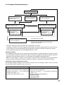
8.4. Emergency Broadcast Sequence
General-purpose broadcast
Depression of the Remote
Microphone's Emergency
broadcast switch
Activation of Alert input*1
by external equipment.
Alternate repetition of Alert tone signal
and Alert announcement
End of set repetition
Live microphone
announcement by
the Remote
Microphone's Talk key
Activation of Emergency Stop input*1
by external equipment
Activation of Evacuation input*1
by external equipment
Alternate repetition of Evacuation tone
signal and Evacuation announcement
Live microphone
announcement by
the Remote
Microphone's Talk key
End of Emergency broadcast
(The unit returns to the general-purpose broadcast
mode it was in immediately before the Emergency
broadcast was started.*2)
*1 Control I/O connector terminal located on the VM amplifier's rear panel
Emergency broadcast can also be stopped by pressing the front panel-mounted Reset key. Note, however,
that the zones the unit was broadcasting to just before the emergency broadcast activation may change.
*2 General-purpose broadcast is not restored depending on its type.
[Emergency mode]
• The emergency mode refers to the state where the VM amplifier is making emergency broadcast or where
the "VM amplifier's broadcast cutoff control" signal is being transmitted from external emergency broadcast
equipment to the VM amplifier (refer to p. 45 "CONTROL I/O CONNECTOR FUNCTIONS").
• When the VM amplifier is placed in the emergency mode that takes precedence over general-purpose
broadcast mode, the Emergency indicators of both the amplifier and the Remote microphone will light.
[Restoration to general-purpose broadcast]
For the general-purpose broadcasts cut off when its mode enters the emergency mode, some are restored
after emergency mode completion, and some are not.
Broadcast to be restored
Broadcast not restored
Broadcast that is not activated by manual
operation of or control from external equipment
• Broadcast from Inputs 1 – 3 not activated by
control input (CTRL 1 – 3).
• Broadcast from BGM Inputs 1 and 2.
Broadcast that is activated by manual operation of or
control from external equipment
• Broadcast from Inputs 1 – 3 activated by control input
(CTRL 1 – 3).
• Broadcast from Remote Microphone
• Telephone paging
• Message broadcast
• Westminster chime
21
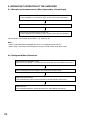
9. BROADCAST OPERATION AT THE AMPLIFIER
9.1. Microphone Announcements (When Operated by Control Input)
Continuously press the microphone press-to-talk key.
(If the microphone is of lock lever type, set the lever to the ON position.)
Make an announcement at the microphone.
Release the microphone press-to-talk key.
(If the microphone is of lock lever type, set the lever to the OFF position.)
For connection of the control input (CTRL 1 – 3), refer to p. 40.
Notes
• TOA's Paging Microphone PM-660D (for Input 1) is equipped with the talk key.
• When using a commonly-used microphone, the press-to-talk switch needs to be made.
9.2. Background Music Broadcast
Select the desired broadcast zone.
(Use the keys for ZONE 1 – 5 or the ALL key located on the VM amplifier front panel.)
Start up background music equipment (CD player or cassette deck)
Adjust the sound volume.
(Use the BGM input volume control located on the VM amplifier front panel.)
Adjust the tone.
(Use the BGM treble/bass control located on the VM amplifier front panel.)
22
10. REMOTE MICROPHONE GENERAL-PURPOSE BROADCAST
10.1. Operation and Display Sections
The panel functions of the operation and display sections differ depending on the amplifier configuration (5
zones or 10 zones) and the use of the Recorded Message Announcement function. The figure shows an
example of the operation panel function for a 5-zone single amplifier configuration with the Voice
Announcement Board. (For samples of the operation panel functions for other amplifier configuration, see p.
14 "Remote Microphone Operation Panel Function.")
Remote microphone RM-200M
Zone indicator
Power indicator (POWER)
Failure indicator (FAULT)
Zone selector key (ZONE 1 – 5)
Group 1&2 broadcast key
(GROUP 1, 2)
Message selector key
(MESSAGE 1 – 5)
Group 1&2 indicator
Talk key (TALK)
All-zone indicator
All-zone broadcast key
(ALL-ZONE)
Message indicator
Microphone
In-use indicator (IN-USE)
Lights green when the RM-200M is in use.
Busy indicator (BUSY)
Flashes orange or green when other connected sound source unit is in use.
Orange: The RM-200M cannot operate.
Green: The RM-200M can interrupt the busy unit.
Notes
• Both the Busy indicator and the In-use indicator indicate the ready status for live microphone
announcements made after selecting the broadcast zone(s) with the All-zone, Zone, or Group selector key.
Their indications have nothing to do with the Recorded message broadcast.
• For priority levels of Remote Microphone live announcements and Recorded messages, see p. 27
"GENERAL-PURPOSE BROADCAST PRIORITY.
[Broadcast volume]
All announcements (including Recorded messages) from the Remote Microphone are broadcast at the
maximum volume level regardless of the settings of the master volume control and zone volume control. Also,
the amplifier performs relay control to permit the announcements to bypass external speaker attenuators.
23
10.2. Broadcast Operation
Following 4 types of broadcasts are possible: All-Zone, Individual Zone, Group, and Message Broadcasts.
This section describes how to make each broadcast.
(1) Simultaneous All-Zone Broadcast Operation
Step 1. Press the ALL-ZONE key.
The All-zone indicator and all zone indicators (1 – 5) will light. (Press
the ALL-ZONE key again to cancel.)
ALL-ZONE
Go to Step 2 on the next page.
(2) Individual Zone Broadcast Operation
Step 1. Select the desired broadcast zone by pressing the ZONE key.
The corresponding zone indicator will light. It is also possible to
simultaneously select 2 or more zones. (To cancel the selection,
press the ZONE key again.)
ZONE 2
Note: When the All-zone indicator remains lit, you can not cancel individual zones by pressing their Zone
keys. In this case, press the ALL-ZONE key to cancel all zones, then select individual Zones with their
keys.
Go to Step 2 on the next page.
(3) Group Broadcast Operation
Individual broadcast zones assigned to Groups 1 and 2 require to be programmed into the VM amplifier.
(See p. 51 "Zone-to-Group assignment.")
Example of Group 1 broadcast
Group 1
(Selected)
Zone 1
Zone 2
Broadcast
Zones
Zone 3
Zone 4
Step 1. Select the desired zone group by pressing the GROUP key.
Both the selected group's indicator and the indicators of the zones
assigned to that group will light. It is also possible to simultaneously
select 2 groups.
GROUP 1
Example of 2-group broadcast
Group 1
(Selected)
Zone 1
Zone 2
Group 2
(Selected)
Zone 3
Zone 4
Zone 5
(To cancel the selection, press the GROUP key again.)
Go to Step 2 on the next page.
24
Broadcast
Zones
(4) Message Broadcast Operation
Messages (1 – 5) assigned to broadcast groups require to be programmed into the VM amplifier. (See p. 52
"Recorded Message-to-Group assignment.")
Example of Message 1 broadcast
Message 1
(Selected)
Group 1
Zone 1
Zone 2
Group 3
Zone 3
Broadcast
Zones
Zone 4
Step 1. Start of broadcast
Select the desired message with the MESSAGE key (MESSAGE 1 – 5).
The Message indicator will light only when broadcast is possible.
Tip: The message broadcast can also be made by applying a control
signal to the VM amplifier's rear-mounted CONTROL I/O
connector. (See p. 45.)
The Recorded voice message is broadcast to its designated broadcast
group.
MESSAGE 1
Recorded
message
Note: When the Message indicator does not light, this indicates that a broadcast is being made from the
sound source given higher priority.
Step 2. End of broadcast
• When the message broadcast is finished, the Message indicator goes out.
• Pressing the MESSAGE key again during broadcast will terminate the broadcast.
Note: Withdrawing the CF card during Message Broadcast will terminate the broadcast without completion.
Operation Common to Simultaneous All-Zone/Individual Zone/Group Broadcast
The operation below follows Step 1 on the previous page.
Step 2. Check the Busy indicator.
(1) When the indicator remains off, other connected equipment are not in use for broadcast.
(2) When the indicator flashes, other connected equipment are in use for broadcast.
Notes
• When the indicator flashes orange, you cannot make any broadcast.
• When the indicator flashes green, your broadcast is allowed to go through by interrupting other broadcast.
The Remote Microphone's TALK key is set for either "press-to-talk" or "lock" operation.
[Press-to-talk operation]
Step 3. Start of broadcast
3-1. Hold down the TALK key.
A start chime tone will be sounded over the broadcast zone.*
(If the chime function is disabled, the microphone announcement can
be made upon depression of the TALK key.)
The In-use indicator will light green.
* The unit is preset for one of 7 different types of chime tones. It is
also possible to disable the chime function. (For details, see p. 30
"CHIME FUNCTION.")
TALK
Start chime
tone
25
3-2. After chime play completion, make an announcement using the microphone.
Live microphone
announcements
TALK key
Step 4. End of broadcast
Releasing the Talk key will sound an end chime tone (only when the
Up/Down 4-tone chime function is employed by the unit), terminating
the broadcast.
Both the all zones indicators and the In-use indicator go out.
TALK
End chime
tone
[Lock operation]
Step 3. Start of broadcast
3-1. One-touch press the TALK key.
TALK
A start chime tone will be sounded over the broadcast zone.*
(If the chime function is disabled, the microphone announcement can
be made upon depression of the TALK key.)
The In-use indicator will light green.
Start chime
tone
* The unit is preset for one of 7 different types of chime tones. It is also possible to disable the chime
function. (For details, see p. 30 "CHIME FUNCTION.")
3-2. After the chime play is finished, make an announcement at the microphone.
Live microphone
announcements
Step 4. End of broadcast
One-touch pressing the TALK key again will sound an end chime
tone (only when the Up/Down 4-tone chime function is employed by
the unit) and terminate the broadcast.
Both the all zones indicators and the In-use indicator go out.
TALK
End chime
tone
26
11. GENERAL-PURPOSE BROADCAST PRIORITY
11.1. Broadcast Source-to-Priority Relationship
• Making broadcast with higher priority cuts off the current lower-priority broadcast, allowing the higher priority
broadcast to go through. Upon completion of the higher priority broadcast, the original broadcast is
automatically restored. For background music (BGM) broadcast (Priority 4), it is also possible to mix it with
other broadcasts or reduce its sound volume without cutting it off. (See p. 29 Priority Function during BGM
Broadcast.)
• Broadcast sound sources to which priority levels 1 – 3 are assigned in the table below can be set to any one
of such priorities with the DIP switch (exception: Priority 3 for Inputs 1 – 3).
• Underlined priority levels represent factory-preset levels.
Broadcast source
Priority level
Input 1 (MIC/LINE)*1 1 2 3 –
Input 2 (MIC/LINE)*1 1 2 3 –
Input 3 (MIC/LINE)*1 1 2 3 –
Telephone paging
1 2 – –
Westminster chime 1 – – –
Remote
1 2 – –
Microphone No.1
Remote
1 2 – –
Microphone No.2
Remote
1 2 – –
Microphone No.3
Remote
1 2 – –
Microphone No.4
Message 1
1 – – –
Message 2
1 – – –
Message 3
1 – 3 –
Message 4
1 – 3 –
Message 5
1 – 3 –
Message 6
Highest priority
(Emergency
Message 7
broadcast)
7 different chimes
BGM 1
BGM 2
–
–
3
–
–
–
–
–
–
–
4
4
DIP switch setting
Switch location Switch No.
Priority 1 or 2 selectable.
Inside the VM
SW2-No. 1
Priority 3 is set when broadcast is amplifier
SW2-No. 2
not externally activated.*2
SW2-No. 3
SW2-No. 4
Set for Priority 1.
––
––
Functional explanation
Priority 1 or 2 selectable.
Set for Priority 1.
Priority 1 or 3 selectable.
RM-200M's right
side panel
No. 3
––
––
Inside the VM
amplifier
SW2-No. 5
SW2-No. 6
SW2-No. 7
For Alert message
For Evacuation message
Priority 3 is set when chime is
externally activated.*3
Set for Priority 4.
––
––
––
––
––
––
*1 Factory-preset to MIC. For the setting, see p. 48 "VM Amplifier's Rear Panel-Mounted Function Switches."
*2 Priority 1 or 2 set for the Inputs 1 – 3 applies to the broadcast activated by their respective Control inputs
(CTRL IN 1 – 3), while Priority 3 applies to the broadcast activated not by the control inputs (by the VM
amplifier's front-mounted zone selector key).
*3 Chime priority
• When the chime is used in Inputs 1 – 3 broadcast, Remote Microphone broadcast or telephone paging, its
priority level is the same (1 or 2) as those assigned to such broadcasts.
• Chime priority level is "3" when activated by the Chime activation input (CONTROL I/O connector pin No.
9). Note that Inputs 1 – 3 need be selected with the front panel selector keys before using the chime.
27
11.2. Broadcast Priority between Equipment with the Equal Priority Level
11.2.1. Priority mode between equipment with the equal priority level
The following 3 priority modes are made available, which can be set using the unit's internal SW2-No. 8 and
SW3-No. 1 switches.
(1) Last-come-first-served priority (factory-preset mode)
The latest broadcast takes precedence, with the earlier broadcast interrupted.
Broadcast source 1
(Made a broadcast first.)
Zone 1
Zone 2
: Broadcast possible
: Broadcast interrupted
Zone 3
Broadcast source 2
(Made a broadcast last.)
Zone 4
(2) First-come-first-served priority
Current broadcast is given priority, and other broadcasts cannot be made.
Broadcast source 1
(Made a broadcast first.)
Zone 1
Zone 2
: Broadcast possible
: Broadcast impossible
Zone 3
Broadcast source 2
(Made a broadcast last.)
Zone 4
(3) Unit number priority (numerical order)
Assign the unit number to the following broadcast sound sources so they can be broadcast in numerical
order.
(A)Remote Microphone (No. 1 – 4)
(B)EV-200 message (No. 1 – 5)
Figure below shows an example for the priority operation between Remote microphones No. 2 and No. 3.
Remote microphone
No. 3 (Made a broadcast first.)
Zone 1
Zone 2
Remote microphone
No. 2 (Made a broadcast first.)
Zone 3
Remote microphone
No. 2 (Made a broadcast last.)
: Broadcast possible
28
Zone 4
Zone 1
Zone 2
Zone 3
Remote microphone
No. 3 (Made a broadcast last.)
: Broadcast impossible or interrupted
Zone 4
11.2.2. Priority function when 2 broadcasts with the equal priority level are simultaneously made
When two or more broadcasts with the equal priority level are simultaneously made, priority mode is as shown
in the following table depending on the type of broadcast sound source and setting switch status.
Broadcast
sound source
Inputs 1 – 3
Telephone paging
Competing priority level (Priority level of simultaneously made broadcasts)
Priority 1
Priority 2
Priority 3 Priority 4
Last-come-first-served Last-come-first- Priority 2 mixing
or first-come-first-served served or first- (selectable)
Mixing
––
1
4
priority * *
come-first-served
(selectable)
priority *1 *4
(selectable)
––
––
Remote
Microphones 1 – 4
1–2
Message
Unit No. priority *4
[Numerical order]
(selectable)
Last-come-first- Unit No. priority *4
served or first- [Numerical order]
come-first-served (selectable)
priority *1 *3 *4
(selectable)
––
3–5
BGM 1 and 2
––
––
––
––
Last-comefirst-served
priority
––
––
––
Mixing
*1 Has nothing to do with the setting of SW2-No. 8 switch (priority mode for the equal priority unit).
*2 Enabled when "Mixed" is selected (factory-preset to "Not mixed") using the unit's internal SW3-No. 2 switch
"Priority 2 mixing."
3
* "Last-come-first-served" priority is selected if the unit's internal SW3-No. 2 switch "Priority 2 mixing" is set
for "Mixed."
4
* Different settings cannot be selected between "priority 1" and "priority 2."
11.3. Priority Function during BGM Broadcast
When other broadcast is made during the BGM broadcast (Priority level 4), the BGM broadcast is as shown in
the table below depending on the priority level of such other broadcast. (The BGM broadcast is restored to the
former state when the other broadcast is completed.)
Priority level of broadcast
overlapping with BGM broadcast
Priority 1
Priority 2
Priority 3
Priority 4 (BGM)
BGM broadcast operation
Cut off.
Cut off*1 or volume is decreased*2 *3.
Volume is decreased*3.
Mixed.
*1 Cut off when broadcast is made by Inputs 1 – 3 set for "Line level" inputs.
*2 Decreased when broadcast is made by Remote Microphone, telephone paging, or Inputs 1 – 3 set for
"Microphone level" inputs.
3
* The attenuation level can be selected from the following using the unit's internal SW4-No.1 and 2 switches.
(1) No attenuation (Mixed)
(2) –28 dB, (audible)
(3) – ∞ dB (inaudible) (factory-preset level)
29
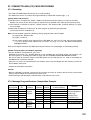
12. CHIME FUNCTION
12.1. Available Chime Tone Types
There are 7 different chimes (one of which can be selected for a pre-announcement chime), and a
Westminster chime for a time signal.
12.1.1. Seven different chime tones
• Six built-in chimes, and 1 pre-recorded chime that is made by recording any preferred sound source are
made available for selection. It is possible to disable the chime function.
• The type of chime can be selected with the unit's rear panel-mounted SETTINGS switches No. 3 – 5. It is
factory-preset to "2-tone chime". (See p. 48 "FUNCTION SWITCH OPERATION.")
Note: Different chime tones cannot be selected for different sound sources.
12.1.2. Six built-in chimes
This lineup consists of the following types.
• 2-tone chime
• 2-tone chime (fast repeat)
• 4-tone chime (Up)*1
• Single-tone chime
• 4-tone chime (Up & Down)*2
• Gong
*1 An ascending 4-tone chime is sounded when the broadcast begins.
*2 An ascending 4-tone chime is sounded when the broadcast begins, and descending 4-tone chime is
sounded upon broadcast completion.
12.1.3. Pre-recorded chime
The optional EV-200 Voice Announcement Board is required to use this function.
A chime tone must be recorded on the Compact Flash (CF) card installed in the EV-200.
The recorded chime tone is assigned to the EV-200's Message 8. (See p. 63 "COMPACTFLASH (CF) CARD
RECORDING.")
12.2. How the Chime Tone Is Used
12.2.1. Chime tone for Inputs 1 – 3
• Either MIC (factory-preset) or LINE input signal level can be set for each input.
Setting switch: SETTINGS switches No. 6 – 8 on the unit's rear panel.
• When the input is set for MIC level and the input source with Priority 1 or 2 is broadcast by remote control
(CTRL IN 1, 2, 3*), a chime tone is automatically sounded when the broadcast is started (and completed).
• When input 1 or 2 is set for LINE level, a chime tone is not sounded when the corresponding source is
broadcast.
• When Input 3 is set for LINE level and the input source with Priority 1 or 2 is broadcast by remote control
(CTRL IN 3*), a chime tone can be made to sound or not to sound when the broadcast is started (and
completed).
Setting switch: The unit's internal SW3-No. 4 switch "Input 3 (LINE) Chime ON/OFF"
(Factory-preset position: Chime OFF)
* The CTRL IN 1, 2, or 3 control input corresponds to the Input 1, 2, or 3, respectively.
12.2.2. Telephone paging chime tone
It is possible to select whether or not to sound a chime tone when the broadcast is started (and completed).
Setting switch: SETTINGS switch No. 2 "Telephone Paging Chime ON/OFF" on the unit's rear panel.
(Factory-preset position: Chime OFF)
30
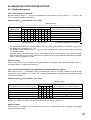
12.2.3. Independent chime activation (remote control)
• A chime tone can be sounded when the broadcast of the sound source (Priority 3) connected to Inputs 1 – 3
not activated by remote control (CTRL IN 1,2,3) is started (and completed).
• Have a chime tone remotely transmitted from the unit's rear panel-mounted CONTROL I/O connector pin No.
9 "Chime activation." (See p. 45 "CONTROL I/O CONNECTOR FUNCTIONS.") Make a chime activation
switch and connect it to between the pin and GND terminal.
Broadcast
sound source
VM amplifier
Chime activation switch
One of Input 1 – 3
Pin No. 9
Chime activation
GND
CONTROL I/O D-sub connector
[Operating procedure]
Step 1. Using the unit's front panel-mounted zone selector key (Zone 1 – 5) or All-zone broadcast key, select
the desired zone(s) to broadcast the sound source connected to Input 1, 2, or 3.
Zone selector key [Zone 1 – 5]
Master volume control
All-zone broadcast key
Zone volume control [Zone 1 – 5]
Note: The chime sound volume depends on the broadcast volume level adjusted with the master volume
control and zone volume control.
Step 2. Turn on (make) the Chime switch. A pre-announcement chime tone will be sent out to the zone(s)
selected in Step 1.
VM amplifier
Chime activation switch
Pin No. 9
Chime activation
Pre-announcement
chime tone
GND
Make
Break
31
Step 3. Turn off (break) the Chime switch when the broadcast is completed. A post-announcement chime
tone will be sent out to the zone(s). (Only when the "ascending/descending 4-tone chime" has been
selected.)
VM amplifier
Chime activation switch
Pin No. 9
Chime activation
Post-announcement
chime tone
GND
Make
Break
Step 4. Press the selected zone selector key (Zone 1 – 5) again to terminate the broadcast.
12.2.4. Westminster chime
• It is possible to set the group of zones over which Westminster chime is sounded. (See p. 51 "Control
input/Telephone paging/Westminster chime-to-Group assignment.")
• A chime tone is remotely sent out to the set zone group by activating the unit's rear panel-mounted
CONTROL I/O connector pin No. 11 "Westminster chime activation." (See p. 45 "CONTROL I/O
CONNECTOR FUNCTIONS.")
32
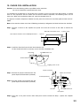
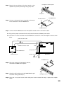
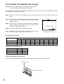
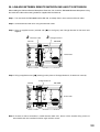
13. CHOKE COIL INSTALLATION
Caution: Leave the following work to a qualified service technician.
Be sure to switch off the power before the work.
If a checkbox for the indication of "The choke coil is installed." on the rear panel of the VM amplifier is marked
with "X", this represents that the choke coil has been installed. Therefore, the following tasks are not
necessary. When you installed the choke coil, mark the checkbox with "X".
To suppress harmonic component radiation from the power line of the unit, install the optional Chock Coil CT200M.
Note: In the countries where use of the CE Marking conformity is obligated, the Choke Coil must be installed.
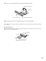
Step 1. Remove 4 screws on the amplifier rear panel and a total of 6 screws on the sides to remove the
cover.
Side: M4 x 8 machine screw ..... 3 pieces each
Rear: M3 x 6 machine screw and M3 plain washer ..... 4 pieces
Step 2. Install the Chock Coil near the AC inlet inside the unit.
Fix the Choke Coil with its accessory screws from the unit bottom side.
Rear panel
CT-200M Choke coil
Bottom side
Tapping screw 4 x 10
Jumper connector
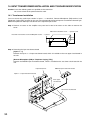
Step 3. Remove the jumper connector from the
power input board connector (CN1202).
Choke coil connector
3
Power input board
4
Step 4. Plug the Choke Coil connector into the
power input board connector (CN1202).
AC inlet
CT-200M Choke coil
Rear panel
Step 5. Using the 4 rear panel screws and 6 side panel screws removed in Step 1, replace the amplifier
cover.
33
14. INPUT TRANSFORMER INSTALLATION AND ITS BOARD MODIFICATION
Caution: Leave the following work to a qualified service technician.
Be sure to switch off the power before the work.
14.1. Transformer Installation
You can convert the audio input section in Input 1 – 3 terminals, Remote Microphone (RM) terminal, and
Telephone Paging (TEL) terminal on the unit from electronically-balanced input to transformer-balanced type.
Solder the optional IT-450 input transformer to the required input section.
Step 1. Remove 4 screws on the amplifier rear panel and a total of 6 screws on the sides to remove the
cover.
Side: M4 x 8 machine screw ..... 3 pieces each
Rear: M3 x 6 machine screw and M3 plain washer ..... 4 pieces
Step 2. Removing the input transformer board
[Inputs 1 – 3]
Remove the Inputs 1 – 3 input transformer board, which is installed on the rear upper circuit board in
the unit.
[Remote Microphone (RM) or Telephone Paging (TEL)]
Remove the RM/TEL input transformer board, which is installed on the rear lower circuit board in the
unit.
Input transformer
RM/TEL input transformer board
Inputs 1 – 3 input transformer board
Rear upper
circuit board
Rear lower circuit board
34
Step 3. Solder the input transformer to the removed input transformer board (5 places).
Note: Be sure not to mistake the solder side for the mounting side.
Step 4. Cut off jumper wires (2 places marked with X for each input).
Note: The jumpers are on the back of the circuit board in the figure below.
[Inputs 1 – 3 input transformer board]
Jumpers for Input 2
Jumpers for Input 1
Jumpers for Input 3
(SJP1305)
(SJP1303)
(SJP1308)
(SJP1306)
INPUT 1
INPUT 2
INPUT 3
(SJP1304)
(SJP1301)
(SJP1307)
(SJP1309)
(SJP1302)
Jumper for Input 1
phantom power supply
Jumper for Input 2
phantom power supply
Jumper for Input 3
phantom power supply
[RM/TEL input transformer board]
(SJP1402)
Jumpers for RM
(SJP1401)
(SJP1404)
RM
Jumpers for TEL
TEL
(SJP1403)
(SJP1405)
Jumper for DC power supply to the RM
Step 5. Replace the input transformer board on the circuit board.
Step 6. Using the 4 rear panel screws and 6 side panel screws removed in Step 1, replace the amplifier
cover.
14.2. Switching Off the Phantom Power Supply
By cutting the following jumper wires on the Inputs 1 – 3 Input Transformer Board, the corresponding input's
phantom power can be switched off. (See the figure above.)
Input 1: SJP1301
Input 2: SJP1304
Input 3: SJP1307
14.3. Instructions When the Sub- and Master VM Amplifiers Are Connected
• Be sure to cut the jumper wires SJP1401, SJP1402, and SJP1403 on the RM/TEL input transformer board in
the sub-VM amplifier.
• To make the Remote Microphone (RM) input transformer-isolated, be sure to install the input transformer on
the RM/TEL input transformer board in the master VM amplifier. In addition, cut the jumper wires SJP1402
and SJP1403 while remaining SJP1401 intact.
35
15. MOUNTING AN OPTIONAL EV-200 VOICE ANNOUNCEMENT BOARD
Caution: Leave the following work to a qualified service technician.
Be sure to switch off the power before the work.
Step 1. Set the DIP switch on the EV-200 Board as shown in the figure.
DIP switch
EV-200 Board
OFF
4
3
1
2
SW 1
ON
O
F
F
4
3
1
2
O
F
F
SW 1
DIP switch
Always set to OFF.
(ON position is for factory test.)
EV-200 surveillance signal output on-off (Switch No. 2)
Be sure to set to ON. (A 1 kHz signal output)
EV-200 surveillance signal output (Switch No. 2)
The EV-200 board always transmits a 1 kHz sine wave signal to an amplifier when the EV-200 Board is not
reproducing audio signals. The amplifier detects the existence of the 1 kHz signal. When the signal does not
exist, the amplifier judges the board's failure and causes the FAULT indicator to light.* (The signal indicating
the EV-200's failure is transmitted from the CONTROL I/O connector.)
* If Switch No. 2 is set to the OFF position, the FAULT indicator lights even when the board is operating
correctly.
Step 2. Remove 4 screws on the amplifier rear panel and a total of 6 screws on the sides to remove the
cover.
Side: M4 x 8 machine screw ..... 3 pieces each
Rear: M3 x 6 machine screw and M3 plain washer ..... 4 pieces
Step 3. Insert the EV-200 connection cable coming from the EV-200 Board into connector CN8 in the
amplifier.
EV-200 connection cable
CN6
EV-200 Board
CN8
CF card connector
Rear panel
36
Step 4. Using 2 screws supplied with the EV-200, mount the EV-200 in the amplifier.
EV-200 connection cable
CN8
EV-200 Board
M3 x 6 machine screw ..... 2 pieces (supplied with the EV-200)
Step 5. Check the DIP switch on the EV-200 Board again for correct setting. (See Step 1.)
Step 6. Using the 4 rear panel screws and 6 side panel screws removed in Step 2, replace the amplifier
cover.
CF Card security cover
Remove 2 screws to detach the security cover when inserting the CF Card into the card slot. Be sure to
replace the cover after inserting the card.
EV-200 Board
CF Card
CF Card security cover
M3 x 6 machine screw (2 pieces)
37
16. MOUNTING AN OPTIONAL SV-200M SURVEILLANCE BOARD
Caution: Leave the following work to a qualified service technician.
Be sure to switch off the power before the work.
Step 1. Set the DIP switch on the SV-200M Board as shown in the figure.
SW 1
SW 2
ON
ON
1 2
SW 1 SW 2
1 2
Communication with VM amplifiers
Be sure to set to ON.
SV-200M Board
Speaker line surveillance activation time
Speaker line surveillance activation time
SW1-1
OFF
SW1-2
OFF
SW2-1
OFF
ON
OFF
ON
OFF
ON
OFF
ON
OFF
ON
ON
OFF
OFF
ON
ON
OFF
OFF
OFF
ON
ON
ON
ON
Setting contents
Automatic activation
disabled
10 minutes intervals
20 minutes intervals
30 minutes intervals
30 minutes intervals
40 minutes intervals
50 minutes intervals
60 minutes intervals
This setting executes failure detection by means of
the "speaker line surveillance activation" signal from
the external control input (SURVEILLANCE I/O 25pin D-sub connector).
Speaker lines are automatically monitored at set
time intervals.
Communications with VM (VM-2120 or VM-2240) amplifier
SW2-2
OFF
ON
Setting contents
Disabled (communications impossible)
Enabled (when SV-200M Board is
installed in VM amplifier)
Step 2. Remove 4 screws on the amplifier rear panel and a total of 6 screws on the sides to remove the
cover.
Side: M4 x 8 machine screw ..... 3 pieces each
Rear: M3 x 6 machine screw and M3 plain washer ..... 4 pieces
38
Step 3. Detach the surveillance I/O blank panel on the
amplifier rear panel by removing 2 fixing snap rivets.
Surveillance I/O blank panel
Snap rivet
D-sub connector
SV-200M Board
Step 4. Unscrew 2 hexagonal sleeves mounted on the 25-pin
D-sub connector on the SV-200M Board.
Hexagonal sleeve
Step 5. Connect the SV-200M Board to the VM amplifier's boards with the connection cables.
5-1. Plug out the jumper connector from the relay board connector (CN1003) shown below.
5-2. Connect the 2 cables attached to the SV-200M to the connectors in the VM amplifier's boards shown
below.
CN6 connection cable
5 -2
CN1003 connection cable
CN1003
CN6
SV-200M Board
D-sub connector
CN8
Relay board
Jumper connector
Rear panel
5 -1
SV-200M Board
Step 6. Using the removed 2 hexagonal sleeves,
mount the SV-200M in the amplifier.
Step 7. Check the DIP switch on the SV-200M Board again
for correct setting. (See Step 1.)
Hexagonal sleeve
Step 8. Using the 4 rear panel screws and 6 side panel screws removed in Step 2, replace the amplifier
cover.
39
17. RACK MOUNTING
Step 1. Remove 4 plastic feet from the unit's bottom side.
Step 2. Remove 2 screws on each side (located near the front).
Step 3. Fix the Rack Mounting Bracket MB-36 to the unit with its accessory screws and plain washers.
Note: Do not use the removed screws in the above step.
Step 4. Mount the unit on an equipment rack using the Bracket's accessory screws and fiber washers.
Note: When mounting the unit in an equipment rack not made by TOA, prepare separately the screws
and washers appropriate for the rack.
VM amplifier
Note: The screws and washers as illustrated are
all supplied with the MB-36.
Plain washer
M4 x 12 screw
3
4
Rack mounting screw
Rack Mounting Bracket MB-36 (optional)
Fiber washer
18. AMPLIFIER INPUT CONNECTION
18.1. Two Amplifiers Stack-Connection
When 2 VM amplifiers are stack-connected, connect the master unit's "PRE OUT" to the sub-unit's "POWER
AMP IN" as well as the LINK-to-LINK connection between both units.
18.2. Microphone Connection to the VM Amplifier
Paging microphone PM-660D
(with short-off press-to-talk switch)
DIN connector
Microphone
XLR type connector
Press-to-talk switch box*
(Remote switch)
* Prepare the switch assembly locally at your end.
40
18.3. Telephone Paging Input Connections
ECH
PBX, main telephone device, etc.
When using a single-core shielded
cable, connect the shielded mesh to
both E and C terminals.
H
Audio signal
C
E
Control signal
Telephone line
41
19. EXTERNAL ATTENUATOR CONTROL WIRING
19.1. 4-Wire System Connection
ATTENUATOR CONTROL relay contact capacity
Withstand voltage: 30 V DC, 125 V AC
Contact current: Under 7 A (DC), under 7 A (AC)
VM amplifier
N1 (NC)
ATTENUATOR
CONTROL*
C
+ External DC power supply
– to activate attenuators
N2 (NO)
H
EXTERNAL SP INPUT
C
DIRECT OUT
H
External attenuators
ZONE 1
H
H
C
C
ZONE 1
Relay control
ZONE 2
H
H
C
C
ZONE 2
Relay control
H
H
C
C
ZONE 3
ZONE 3
Relay control
ZONE 4
H
H
C
C
ZONE 4
Relay control
H
H
C
C
ZONE 5
ZONE 5
Relay control
* This figure shows the relay operation status when the VM amplifier's power is switched off, when it is making
All-zone or emergency broadcast or when its broadcast is cut off due to control from external equipment in
emergency broadcast mode.
42
19.2. 3-Wire System Connection
Note: 3-wire system cannot be used with the SV-200M board.
ATTENUATOR CONTROL relay contact capacity
Withstand voltage: 30 V DC, 125 V AC
Contact current: Under 7 A (DC), under 7 A (AC)
VM amplifier
N1 (NC)
C
ATTENUATOR
CONTROL*1
N2 (NO)
H
EXTERNAL SP INPUT
C
DIRECT OUT
*2
H
External attenuators
ZONE 1
H
H (100 V)
C
C (0 V)
ZONE 1
EMERGENCY
ZONE 2
H
H (100 V)
C
C (0 V)
ZONE 2
EMERGENCY
H
H (100 V)
C
C (0 V)
ZONE 3
ZONE 3
EMERGENCY
ZONE 4
H
H (100 V)
C
C (0 V)
ZONE 4
EMERGENCY
H
H (100 V)
C
C (0 V)
ZONE 5
ZONE 5
EMERGENCY
*1 This figure shows the relay operation status when the VM amplifier's power is switched off, when it is
making All-zone or emergency broadcast or when its broadcast is cut off due to control from external
equipment in emergency broadcast mode.
*2 May be connected to any C terminal. (This C terminal is located closest to N1 terminal.)
43
20. CHANGING THE SPEAKER LINE VOLTAGE
Caution: Leave the following work to a qualified service technician.
Be sure to switch off the power before the work.
The VM amplifier's speaker line voltage is set for 100 V line output. For 50 V or 70 V line applications, change
internal connector wiring as shown below.
Step 1. Remove 4 screws on the amplifier rear panel and a total of 6 screws on the sides to remove the
cover.
Step 2. Pull the cable connector (9-pin) connected to CN1102
connector on the circuit board with the zone volume control
(selector switch).
Step 3. Change wires inserted into the cable connector for different
wires according to color-coding shown in the table below to
switch to the desired line voltage.
CN1102 connector
Step 4. Connect the cable connector to the circuit board.
Step 5. Using the 4 rear panel screws and 6 side panel screws
removed in Step 1, replace the amplifier cover.
VM amplifier's front panel
Connector pin assignment
Speaker line voltage
100 V
70 V
50 V
1
White
Violet
Blue
2
Violet
Blue
Green
CN1102 Connector Pin Number
3
4
5
6
7
Blue
Green Yellow Orange
Red
Green Yellow Orange
Red
Brown
Yellow Orange
Red
Brown
White
8
Brown
White
Violet
Speaker line voltage/impedance
Speaker line voltage VM-2120
100 V
83 Ω
70 V
42 Ω
50 V
21 Ω
VM-2240
42 Ω
21 Ω
10 Ω
How to remove cables from connector
Pull out the cable pressing the lock spring with a pointed object like tweezers as shown below.
Pull out the cable.
Press the lock spring.
1
9
44
9
Black
Black
Black
21. CONTROL I/O CONNECTOR FUNCTIONS
The rear panel-mounted Control I/O connector enables the VM amplifier to be controlled or monitored by
connected external equipment. Referring to the pin arrangement and functions, prepare the matching D-sub
male connector (screw-lock type) for connection to the external equipment. (See p. 9, 10 No. 30 CONTROL
I/O connector.)
VM amplifier's D-sub female connector
CONTROL I/O
13
1
Locking nut: 4-40 UNC
25
14
CONTROL I/O connector pin function table
Pin
No.
1
2
3
4
5
6
7
8
Signal name
AC power ON
DC power ON
Message 1 activation
Message 2 activation
Message 3 activation
Message 4 activation
Message 5 activation
VM amplifier's
broadcast cutoff control
IN
/OUT
Signal/logic
OUT
OUT
IN
IN
IN
IN
IN
IN
Active Low
Active Low
One-shot make
One-shot make
One-shot make
One-shot make
One-shot make
At make
At break
Chime activation
(6 built-in chimes)
Power ON/OFF control
IN
Westminster chime
activation
Emergency alert
activation
IN
Break-to-Make edge
Make-to-Break edge
Break-to-Make edge
Make-to-Break edge
One-shot make
IN
One-shot make
Emergency stop
activation
Emergency evacuation
activation
IN
One-shot make
IN
One-shot make
15
Failure indicator control
IN
At make
16
17
18
19
20
21
GND
GND
GND
GND
GND
Power switch on
9
10
11
12
13
14
IN
OUT
Active Low
Function/status
When AC power is on
When DC power is on
Activates EV-200 Board's Message 1.*1
Activates EV-200 Board's Message 2.*1
Activates EV-200 Board's Message 3.*1
Activates EV-200 Board's Message 4.*1
Activates EV-200 Board's Message 5.*1
Cuts off the VM amplifier's power amplifier
output.* 1 * 2 (External signals applied to
EXTERNAL SP INPUT go through to the
speakers.)
The VM amplifier's power amplifier output is
resumed.
Activates a start chime tone.
Activates an end chime tone (4-tone Down).
Turns power on.
Turns power off.
Activates the internal Westminster chime unit.
Places the unit in "Emergency broadcast" mode,
during which time an "Alert" announcement and
an "Evacuation" announcement are broadcast. *1
Resets the unit from "Emergency broadcast"
mode.
Places the unit in "Emergency broadcast" mode,
during which time an "Evacuation" announcement
is repeated. *1
The FAULT indicator lights to indicate external
equipment failure.
When the power switch is on by means of
manual or external control
45
Pin
No.
Signal name
IN
/OUT
Signal/logic
22
Communications error
OUT
Active Low
23
24
Failure indication
Emergency broadcast
on
OUT
OUT
Active Low
Active Low
25
EV-200's failure
OUT
Active Low
Function/status
When communications cannot be achieved
between the RM-200M and the VM amplifier
or between VM amplifiers (High state when
communications are restored.)
When the FAULT indicator lamp is on
When an Emergency broadcast is performed
by the VM amplifier or the external equipment.
(See the description of Pin 8 VM amplifier's
broadcast cutoff.)
When the EV-200 Voice Announcement
Board fails.*1
*1 Requires installation of the optional EV-200 Voice Announcement Board.
*2 Use this pin to cut off the VM amplifier's power amplifier output to allow the "Emergency broadcast" initiated
by connected external equipment to go through.
[Electrical characteristics]
Input
Open voltage:
3.3 V DC
Short-circuit current: Under 1 mA
Activation:
No-voltage make contact (one-shot signal is shown below.)
Over 100 ms
Output
Circuit:
Open collector (See below.)
Withstand voltage: 30 V DC
Control current:
Under 10 mA
Control current
46
22. SURVEILLANCE I/O CONNECTOR FUNCTIONS
The rear panel Surveillance I/O connector* permits "Speaker Line Reference Impedance Measurement (Initial
Setting)" and "Speaker Line Check" to be enabled and monitored by connected external equipment. Referring
to the pin arrangement and functions, prepare the matching D-sub male connector (screw-lock type) for
connection to the external equipment. (See p. 11 No. 41 SURVEILLANCE I/O connector.)
* Requires installation of the optional SV-200M Surveillance Board.
SV-200M's D-sub female connector
13
SURVEILLANCE I/O
1
Locking nut: 4-40 UNC
25
14
SURVEILLANCE I/O connector pin function table
Pin
No.
Signal name
IN
/OUT
Signal/logic
Function/status
1
2
3
4
5
6
7
8
9
10
11
12
13
Zone 1 short
Zone 1 Disconnection
Zone 2 short
Zone 2 Disconnection
Zone 3 short
Zone 3 Disconnection
Zone 4 short
Zone 4 Disconnection
Zone 5 short
Zone 5 Disconnection
Ground fault
Power amplifier failure
Setting/checking busy
OUT
OUT
OUT
OUT
OUT
OUT
OUT
OUT
OUT
OUT
OUT
OUT
OUT
Active Low
Active Low
Active Low
Active Low
Active Low
Active Low
Active Low
Active Low
Active Low
Active Low
Active Low
Active Low
Active Low
14
Initial setting error
OUT
Active Low
Speaker line check
activation
Speaker line initial
setting activation
IN
One-shot make
Check of the speaker line impedance starts.
IN
One-shot make
Measurement of the speaker line reference
impedance (Initial setting) starts.
Not used.
15
I
22
23
24
25
Zone 1 speaker line is shorted.
Zone 1 speaker line is disconnected.
Zone 2 speaker line is shorted.
Zone 2 speaker line is disconnected.
Zone 3 speaker line is shorted.
Zone 3 speaker line is disconnected.
Zone 4 speaker line is shorted.
Zone 4 speaker line is disconnected.
Zone 5 speaker line is shorted.
Zone 5 speaker line is disconnected.
Some of speaker lines are grounded.
Power amplifier is faulty.
During measurement of the speaker line
reference impedance (Initial setting) or during
check of the speaker lines.
The speaker line reference impedance
couldn't be measured successfully.
(The measured impedance exceeds the
expected range or is unstable.)
Not used.
47
[Electrical characteristics]
Input
Open voltage:
3.3 V DC
Short-circuit current: Under 1 mA
Activation:
No-voltage make contact (one-shot signal is shown below.)
Over 100 ms
Output
Circuit:
Open collector (See below.)
Withstand voltage: 30 V DC
Control current:
Under 10 mA
Control current
23. FUNCTION SWITCH OPERATION
23.1. VM Amplifier's Rear Panel-Mounted Function Switches
Set the rear panel-mounted SETTINGS switch (p. 9, 10 No. 29) as shown below.
1 2 3 4 5 6 7 8
ON
All switches No. 1 – 8 are factory-preset to the OFF position.
SETTINGS
Switch No.
1
2
3
4
5
6
7
8
4
Function
Phantom Power* Telephone Paging Chime Selection Input 3 Input 2 Input 1
See the Chime Mic
OFF (Up position)
OFF
Chime ON
Mic
Mic
Selection table
ON (Down position)
ON
Chime OFF
Line
Line
Line
Chime Selection table
Switch No.
3
4
5
OFF OFF OFF
OFF OFF ON
OFF ON OFF
OFF ON ON
ON OFF OFF
ON OFF ON
ON ON OFF
ON ON ON
48
Chime Tone
2-Tone Chime
2-Tone Chime (Fast Repeat)
4-Tone Chime (Up) *1
Single-Tone Chime
4-Tone Chime (Up & Down) *2
Gong
Pre-recorded Chime *3
OFF
*1 An ascending 4-tone chime is sounded when the
broadcast begins.
2
* An ascending 4-tone chime is sounded when the
broadcast begins, and a descending 4-tone chime
is sounded upon broadcast completion.
3
* The chime sound source must be pre-recorded into
a CF (CompactFlash) card to be inserted into the
optional EV-200 Voice Announcement Board. (See
p. 36.)
4
* Simultaneously turns on or off the phantom power of
Inputs 1 – 3. See p. 35 for the method to switch off
the phantom power for the individual Inputs 1 to 3.
23.2. VM Amplifier's Internal Function Switches
Caution: Leave the following work to a qualified service technician.
Be sure to switch off the power before the work.
Step 1. Remove 4 screws on the amplifier rear panel and a total of 6 screws on the sides to remove the
cover.
Side: M4 x 8 machine screw ..... 3 pieces each
Rear: M3 x 6 machine screw and M3 plain washer ..... 4 pieces
Step 2. Set the amplifier's internal DIP switches SW2, SW3, and SW4 according to the table below.
Step 3. Replace the amplifier cover using the screws removed in Step 1.
SW4
SW3
SW2
Internal DIP switches
SW4
SW3
ON
1 2
SW2
ON
ON
1 2 3 4 5 6 7 8
1 2 3 4 5 6 7 8
VM amplifier's front panel
SW2 switch setting (All switches are factory-preset to OFF position.)
Switch No.
1
2
3
4
5
6
7
Function
Inputs 1 – 3
TEL Paging
Voice Announcement Board's
Broadcast Priority Level Priority Level
Message Priority Level
Input 1 Input 2 Input 3
Message 3 Message 4 Message 5
ON
1
1
1
1
3
3
3
OFF
2
2
2
2
1
1
1
8
Priority Mode
for Same
Priority Unit
Unit No. Priority
(Numerical order)
First/Last
Priority
SW3 switch setting (All switches are factory-preset to OFF position.)
Switch No.
Function
1
First/Last
Priority*
2
Priority 2
Mixing
3
Mode after
Emergency Talk
ON
First-come
first-served
Last-come
first-served
Mixed
Silent
OFF
Not mixed
Evacuation
message
4
Input 3/LINE
(Input 3/MIC)
Chime On/Off
On
(off)
Off
(on)
5
Unit Type
Sub-unit
Master
unit
6
7
8
No. of Connected
Units
See the Connected
unit No. table on the
next page.
* This function is set in relation to the SW2-8 switch. (See p. 27 "GENERAL-PURPOSE BROADCAST
PRIORITY" for details.)
49
Connected unit No. table (SW3)
Switch No.
6
7
8
OFF OFF OFF
ON
OFF OFF
OFF
ON
OFF
ON
ON
OFF
OFF OFF
ON
ON
OFF
ON
No. of Connected Units*
0
1
2
3
4
5
* The total number of one Sub-VM amplifier and up to 4
Remote Microphones (excluding the Master amplifier
and Remote Microphone Extension)
SW4 switch setting (Both switches are factory-preset to ON position.)
Switch No.
1
2
OFF
OFF
ON
ON
Don't care
BGM broadcast volume attenuation*
No attenuation
–28 dB (just audible)
– ∞ dB (inaudible)
* Determines the attenuation level when the broadcast of higher priority (level 2 or 3) overrides the BGM
broadcast (priority level 4). (See p.27 "GENERAL-PURPOSE BROADCAST PRIORITY)
23.3. Remote Microphone's Function Switches
1 2 3 4 5 6
ON
Switch No.
Function
ON
Function setting switch (No.23)
1
2
RM Unit No.
(See the RM Unit No.
table below.)
OFF
Note
The switch is actually installed upside down.
3
Broadcast
Priority*
2
1
4
Talk key
operation
Press-to-talk
type
Talk lock type
5
Emergency
switch
Enable
Disable
6
Compressor
On
Off
* One of 2 priorities can be set for each Remote microphone. (See p.27 "GENERAL-PURPOSE
BROADCAST PRIORITY.")
RM (RM-200M) Unit No. table
Switch No.
1
2
ON
ON
OFF ON
ON OFF
OFF OFF
RM Unit No.
No. 1
No. 2
No. 3
No. 4
All switches No. 1 – 6 are factory-preset to the ON position.
50
24. BROADCAST GROUP/ZONE SETTING
24.1. Routing Assignment
24.1.1. Zone-to-Group assignment
Desired broadcast zones (1 – 10) can be combined into one broadcast group (Groups 1 – 5). (See p. 53
"Zone-to-Group Assignment Operation.")
Setting example (
mark indicates "Set" state.)
Setting content
Broadcast Group
(Setting item)
Group 1
Group 2
Group 3
Group 4
Group 5
1
2
Broadcast Zone 1 – 10
3 4 5 6 7 8
9
ALL zones (Marking a check bypasses the
10 external attenuator on all-zone broadcast.)
*2
Master unit zone
Sub-unit zone
For Remote Microphone operation*1
*1 The Remote Microphone can select broadcast zones by pressing the GROUP 1 or GROUP 2 key instead
of individual zone selector keys 1 – 10.
*2 The broadcast zone settings (zones 1 – 10) cannot be changed unless the ALL zones setting is canceled
(i.e. "Not Bypassed").
If the ALL zones (attenuator bypass) item is set to "Bypassed," as seen in Group 4 in the above example.
Setting "Bypassed" shorts the "N1" terminal to "C" terminal on the rear-mounted ATTENUATOR CONTROL
when an all-zone broadcast is made.
[Default setting]
Only the zone with the same number as the group number is assigned to each group. (Example: Zone 1 is
assigned to Group 1, and Zone 5 to Group 5.)
24.1.2. Control input/Telephone paging/Westminster chime-to-Group assignment
When control inputs 1 – 3, telephone paging, or Westminster chime is activated, broadcast is made to their
respectively assigned groups 1 – 5. (See p. 56 "Control Input/Telephone Paging/Westminster Chime-to-Group
Assignment Operation." )
Setting example (
mark indicates "Set" state.)
Setting content
Control Input/Telephone
Paging/Westminster Chime (Setting item)
Input 1
Input 2
Input 3
TEL paging
Westminster chime
Broadcast Group
1 2 3 4 5
ALL zones (Marking a check bypasses the
external attenuator on all-zone broadcast.)
Broadcast is made to the zones selected in the above Zone-to-Group assignment.
[Default setting]
Only "All zones" is assigned to each setting item from Input 1 to Westminster chime. (Example: TEL paging
setting in the above table)
51
24.1.3. Recorded Message-to-Group assignment
Activated messages (1 – 5) are broadcast to their respectively assigned groups 1 – 5. (See p. 58 "Recorded
Message-to-Group Assignment Operation.")
Setting example (
mark indicates "Set" state.)
Setting content
Recorded Message
(Setting item)
Message 1
Message 2
Message 3
Message 4
Message 5
Broadcast Group
1 2 3 4 5
ALL zones (Marking a check bypasses the
external attenuator on all-zone broadcast.)
Messages are broadcast to the zones selected in the above Zone-to-Group assignment.
[Default setting]
Only "All zones" is assigned to each of Messages 1 – 5. (Example: Message 3 setting in the above table)
24.2. Operating Keys
ZONE 1 – 5 keys*2
ALL indicator
1
ZONE 1 – 5 indicators*
*2
Master VM amplifier
LINK connector (rear)
Reset key
ALL key
POWER switch
ZONE 6 – 10 indicators
Sub-VM amplifier
LINK connector (rear)
ZONE 6 – 10 keys
*1 See p. 55 "Indicator status."
*2 Function as the indicators or keys for the setting items (Group 1 – 5, Message 1 – 5, etc.) as well according
to the setting steps.
• Note that the Sub-unit's zone selector keys function as the ZONE 6 through ZONE 10 keys.
• The figure above shows a 10-zone broadcast system where master unit and sub-unit are linked together.
A 5-zone broadcast system requires the master unit only.
52
24.3. Zone-to-Group Assignment Operation
• Here, the operation example of assigning Broadcast Zones 2 – 4 to Group 2 will be explained for a 5-zone
(Master unit only) configuration. (See p. 51 "Group 2 to zone" setting example.)
• In the case of 10 broadcast zones (i.e. connection of a master unit to a sub-unit), use the sub-unit's Zone
selector keys 1 – 5 as Zone keys 6 – 10.
Lighting status
Extinguished
Lighting
Flashing
Quick flashing*
Slow flashing*
* See p. 55 Indicator status.
Step 1. Entry to broadcast group setting mode
Press and release the Reset key while holding down the
ZONE 1 and ZONE 2 keys. When all indicators for
Zones 1 – 5 begin to flash (2 – 3 seconds after), release
both the ZONE 1 and ZONE 2 keys.
Use a precision screwdriver or other long, pointed
object (2.5 mm in diameter and over 30 mm in length)
when pressing the Reset key.
Note: Even when a sub-amplifier is connected, perform
this setting entry operation on the master
amplifier only.
The unit will be placed in broadcast group setting mode.
The 5 indicators for ZONE 1 through ZONE 5 begin to
flash. (They indicate Group 1 through Group 5.)
Another 5 indicators for ZONE 6 through ZONE 10 will
also flash if a Sub-amplifier is connected.
Step 2. Group number selection (Example: Group 2)
Press the ZONE 2 key to select the Group 2.
ZONE 1
ZONE 2
Group 1
ZONE 1
Reset
Group 5
ZONE 2
ZONE 3
ZONE 4
Group 1
ZONE 5
ALL
Group 5
The ZONE 2 indicator will slowly flash* to indicate that
Group 2 was selected.
Pressing other selector key will change the group
number
ZONE 1
ZONE 2
ZONE 3
ZONE 4
ZONE 5
ALL
Step 3. Group number programming
Press the POWER switch.
The Group 2 will be programmed and the unit will be
placed in Zone Selection mode for Group 2.
• The ZONE 2 indicator changes from "quick flashing" to
"slow flashing*," indicating that Group 2 was selected
and that Zone 2 was set (default setting).
• The remaining indicators, ZONE 1, ZONE 3, ZONE 4,
ZONE 5, and ALL flash. (This indicates that Zones 2
was set as default.)
Zone 1
ZONE 1
ZONE 2
Group 2
(Zone 2)
Zone 5
ZONE 3
ZONE 5
ZONE 4
ALL
53
Step 4. Zone number setting (Example: Zones 2, 3, and 4)
Press the ZONE 3 and ZONE 4 keys to select the corresponding zones. (As a result, The Zones 2, 3,
and 4 are selected.)
• Indicators for ZONE 3 and ZONE 4 will light.
(This represents that Zones 3 and 4 were selected.)
Zone 1
Group 2
(Zone 2)
Zone 5
ZONE 3
ZONE 5
• Indicators for ZONE 1 and ZONE 5 will flash.
(This represents that Zones 1 and 5 are not selected.)
• The ZONE 2 indicator remains "slow flashing*." (This
represents that Group 2 has already been selected,
and that Zone 2 is currently selected as default
setting.)
ZONE 1
ZONE 2
ZONE 4
ALL
Note: For "All zones" settings in this step, refer to the section "All zones setting and its cancellation"
below.
Step 5. Programming of the zone number setting
Press the POWER switch.
The Zones 2, 3, and 4 will then be programmed,
automatically returning the procedure to Step 2.
According to the instructions in Step 2, set the next
zone group. (Repeat Steps 2 through 5.)
POWER
Step 6. Group setting completion
After completing all group settings, press the Reset key
using a pointed object.
This completes the setting mode, returning the unit to
broadcast standby mode.
Reset
* See p. 55 Indicator status.
[All zones setting and its cancellation]
Pressing the ALL key selects all zones and places the unit in the
external attenuator bypass mode. The ALL indicator and the
indicators for ZONE 1 and ZONE 3 – ZONE 5 will light, while the
ZONE 2 indicator will slowly flash.
Zone 1
ZONE 1
When the ALL indicator is steadily on, if the ALL key is pressed,
the selection of all zones will be cancelled. Then, the setting
returns to the situation before the "ALL zones" was set.
Zone 1
ZONE 1
54
ZONE 2
ZONE 2
Group 2
(Zone 2)
Zone 5
ZONE 3
ZONE 5
ZONE 4
Group 2
(Zone 2)
Zone 5
ZONE 3
ZONE 5
ZONE 4
ALL
ALL
[Group setting contents check]
Complete Steps 1, 2, and 3, then jump to Steps 5 and 6 without executing Step 4 (zone number setting).
[Indicator status]
(1) Flashing
Equal duration "ON" and "OFF" indicator flashing.
Indicates that the corresponding setting contents (Example: Zone number) have not yet been selected
(setting contents can be selected).
Zone 2 deselected (selectable)
ON (Lighting)
OFF (Extinguished)
ON = OFF
ZONE 2
(2) Quick flashing
Indicator flashing with a shorter "ON" duration than "OFF" duration.
Indicates that the corresponding setting item (Example: Group No. 2) was already selected when in the
state of (1) above.
Example: The indicator quickly flashes when Group 2 was selected, but Zone 2 has not yet been selected
(Zone 2 selectable).
Group 2 selected, Zone 2
deselected (selectable)
ON
OFF
ON < OFF
ZONE 2
Zone 2 selected
(3) Steady on
Indicates that the setting contents were selected.
ZONE 2
(4) Slow flashing
Indicator flashing with a longer "ON" duration than "OFF" duration.
Indicates that the corresponding setting item (Example: Group No. 2) was already selected when in the
state of (3) above.
Example: The indicator slowly flashes when both Group 2 and Zone 2 were selected.
Group 2 selected, Zone 2 selected
ON
OFF
ON > OFF
ZONE 2
55
[Operation for zone selection and its cancellation]
• Pressing a currently flashing or quickly flashing zone key for any zone not selected will select that zone (the
zone indicator then remains steadily lit or slowly flashes).
• Conversely, if a currently selected zone key is pressed, that zone will then be deselected. ("Selected" and
"deselected" states are alternately changed with each press of the key.)
[Dual indication of group and zone selections]
The indicators for set zones remain steadily on, while those for unset zones flash. However, if a zone with the
same number as the group number is selected, the corresponding indicator slowly flashes*. (This provides a
dual indication of Group and Zone selection.) When the same number zone is not selected, the indicator
quickly flashes*. (This provides a dual indication of Group selection and Zone deselection.)
* See p. 55 Indicator status.
24.4. Control Input/Telephone Paging
/Westminster Chime-to-Group Assignment Operation
Here, the operation example of assigning Input 1 to Broadcast Groups 1, 2, and 3 will be explained.
(See p. 51 "Input 1 to group" setting example.)
Step 1. Entry to setting mode
Press and release the Reset key while holding down the
ZONE 1 and ZONE 4 keys. When all indicators for
Zones 1 – 5 begins to flash (2 – 3 seconds after),
release both the ZONE 1 and ZONE 4 keys.
The unit will be placed in setting mode.
The 5 indicators for ZONE 1 through ZONE 5 begin to
flash. (They indicate Input 1 through Westminster
chime.)
ZONE 1
Input 1
ZONE 1
Step 2. Setting item selection (Example: Input 1)
Press the ZONE 1 key to select the Input 1.
Note that the ZONE 1 key functions as the selector key
for "Input 1."
ZONE 4
Reset
Westminster chime
ZONE 2
Input 1
ZONE 3
ZONE 4
ZONE 5
ALL
TEL paging
Input 3
Westminster
chime
Input 2
The ZONE 1 indicator will slowly flash* to indicate that
Input 1 was selected.
Pressing other selector key will change the setting item
assigned to each zone key as shown on the right.
ZONE 1
Step 3. Setting item programming
Press the POWER switch.
The Input 1 will be programmed and the unit will be
placed in Group Selection mode for Input 1.
The ZONE 1 indicator changes from "quick flashing" to
"slow flashing", while the remaining indicators for zones
2 – 5 and "ALL" (All zones) stay steadily on. This
represents that Input 1 has been selected, and "ALL
zones" (not "ALL groups") has been set. (Default
setting)
56
ZONE 2
ZONE 3
ZONE 4
Zone 1
(Input 1)
ZONE 1
ZONE 2
ZONE 3
ZONE 5
ALL
Zone 5
ZONE 4
ZONE 5
ALL
Step 4. Group number setting (Example: Groups 1, 2, and 3)
Group 1
(Input 1)
4-1. Pressing the ALL key will cancel the "ALL zones"
setting, causing the ALL indicator and the indicators for
ZONES 2 – 5 to flash. The ZONE 1 indicator changes
from "slow flashing" to "quick flashing," indicating that
Input 1 was selected but Group 1 was not.
Note: The setting returns to the situation before the
"ALL zones" was set.
ZONE 1
ZONE 2
Group 5
ZONE 3
ZONE 4
ZONE 5
ALL
4-2. Press the ZONE 1, ZONE 2, and ZONE 3 keys to select
the Groups 1 through 3.
• The ZONE 1 indicator changes from "quick flashing" to
"slow flashing*," indicating that Input 1 was selected
and that Group 1 was set.
• Indicators for ZONE 2 and ZONE 3 become steadily
on. (This represents that Groups 2 and 3 are
selected.)
• Indicators for ZONE 4, ZONE 5, and ALL remain
flashed. (This represents that Groups 4 and 5 were not
selected.)
Step 5. Programming of the group number setting
Press the POWER switch.
The Groups 1, 2, and 3 will then be programmed,
automatically returning the procedure to Step 2.
According to the instructions in Step 2, set the next
setting item. (Repeat Steps 2 through 5.)
Step 6. Setting completion
After completing all item settings, press the Reset key
using a pointed object.
This completes the setting mode, returning the unit to
broadcast standby mode.
Group 1
(Input 1)
ZONE 1
ZONE 2
Group 5
ZONE 3
ZONE 4
ZONE 5
ALL
POWER
Reset
* See p. 55 Indicator status.
[Message setting contents check]
Complete Steps 1, 2, and 3, then jump to Steps 5 and 6 without executing Step 4 (group number setting).
[Operation for group selection and its cancellation]
• Pressing a currently flashing or quickly flashing zone key for any group not selected will select that group
(the zone indicator then remains steadily lit or slowly flashes).
• Conversely, if a currently selected zone key is pressed, that group will then be deselected. ("Selected" and
"deselected" states are alternately changed with each press of the key.)
[Dual indication of setting item and group selections]
The indicators for set groups remain steadily on, while those for unset groups flash. However, if a group to
which the setting item is assigned as in the figure of Step 2 is selected, the corresponding indicator slowly
flashes*. (This provides a dual indication of Setting item and Group selection.) When that group is not
selected, the indicator quickly flashes*. (This provides a dual indication of Setting item selection and Group
deselection.)
* See p. 55 Indicator status.
57
24.5. Recorded Message-to-Group Assignment Operation
Here, the operation example of assigning Recorded Message 1 to Broadcast Groups 1, 3, and 4 will be
explained. (See p. 52 "Message 1 to group" setting example.)
Step 1. Entry to recorded message setting mode
Press and release the Reset key while holding down the
ZONE 1 and ZONE 3 keys. When all indicators for
Zones 1 – 5 begins to flash (2 – 3 seconds after),
release both the ZONE 1 and ZONE 3 keys.
ZONE 1
ZONE 3
Message 1
Reset
Message 5
The unit will be placed in recorded message setting
mode.
The 5 indicators for ZONE 1 through ZONE 5 begin to
flash. (They indicate Message 1 through Message 5.)
ZONE 1
ZONE 2
ZONE 3
ZONE 4
ZONE 5
ALL
Operations of Steps 2 – 6 described hereafter are the same as those described in the previous section Control
input/Telephone paging/Westminster chime-to-Group assignment. However, read 5 setting items of Inputs 1 –
3, TEL paging, and Westminster chime as Messages 1 – 5.
Group 1
(Message 1)
Shown on the right is the status of each indicator that results
from the group number setting (Example. Groups 1, 3, and 4)
performed in Step 4.
ZONE 1
58
ZONE 2
ZONE 3
Group 5
ZONE 4
ZONE 5
ALL
25. LINKAGE BETWEEN REMOTE MICROPHONE AND ITS EXTENSION
When adding the RM-210 Remote Microphone Extension, link it with the RM-200M Remote Microphone using
the extension cable and mounting hardware supplied with the RM-210.
Step 1. Turn over both the RM-200M and the RM-210, and keep them in close contact with each other.
Step 2. Connect between both units using the extension cable.
Step 3. Using 4 supplied screws (marked with [
together.
2
Extension cable
] in the figure) and Linkage Bracket B, link both units
3
Linkage bracket B
RM-210
RM-200M
Bottom side
Step 4. Using 8 supplied screws ([
] marking) and 2 pieces of Linkage Bracket A, fix both units securely.
Linkage bracket A
RM-210
RM-200M
Bottom side
Note: If incorrect or loose connection is found between both units, loosen all the bracket fixing screws to
disassemble the units and then link them again with the screws.
59
26. NAME LABEL PREPARATION
26.1. Amplifier's Label Preparation
• Use the supplied labels to indicate the names of each input and output on the front panel. Write the name in
the label, and affix it under each input or output volume control. See p. 8 "NOMENCLATURE AND
FUNCTIONS" for the place the label is affixed to. When making the label with a word processor, etc., be
sure that its size is no larger than 24 mm x 6 mm.
• Use the supplied
label to indicate the set position of each volume control.
26.2. Remote Microphone's Label Preparation
26.2.1. Name label type and usable paper
Label type
Name label A: For setting on the RM-200M's left side
Name label B: For setting on the RM-200M's right side, and RM-210
Paper: Under 0.2 mm thick
26.2.2. Preparing the name label
(1) Preparation by hand
Copy the "Pattern paper for hand writing" on the next page. After writing a name, cut out the pattern paper
aligning it with the cutting guidelines.
(2) Preparation by using a PC or word processor
Prepare and print according to the instructions given in the "Dimensional diagram for printing devices" on
p. 62. Then cut out to the instructed size.
26.2.3. Inserting the name label
• Fully insert the name label cut out to the instructed size into the label entry slit.
• To remove the label, pull it out of the slit using the tip of knife blade.
Zone 1
Name label B
(already prepared and cut out)
Zone 2
Zone 3
Zone 4
Zone 5
Remote
microphone
RM-200M
Name label entry slit
Name label A
60
[Pattern paper for hand writing]
Name label A
Name label B
Cutting guideline
Shown in actual size
61
[Dimensional diagram for printing devices]
Name label B
Cutting size: 30 x 134 mm
30
30
POWER
ZONE 1
13
Name label A
Cutting size: 30 x 108 mm
FAULT
26
ZONE 2
GROUP 1
ZONE 5
13
MESSAGE 1
GROUP 2
13
MESSAGE 2
MESSAGE 3
7
ALL-ZONE
13
MESSAGE 4
7
MESSAGE 5
Names are assigned as an example.
Unit: mm
62
134
ZONE 4
9 x 13 (=117)
26
108
EMERGENCY
ACTIVATION
ZONE 3
27. COMPACTFLASH (CF) CARD RECORDING
27.1. Recording
• Use TOA's EV-350R Digital Announcer for CF card recording.
• The table below shows an example of Program/Sentence composition for Messages 1 – 8.
[Setting items and contents]
(1) Set the items in "Program No." (P001 – P008) and "Playback method" columns as shown in the table.
Besides, be sure to set the "Busy output (at repeat interval)" (omitted in the table) for ON (factory-preset).
(2) The contents in "Number of repeats", "Repeat interval", and "Sentence No. (or Silent Section)" are given
for an example.
(3) Determine the optimum "Output level" for each Program by performing the operation.
(Factory-preset level: Graduation 6)
Note: The VM amplifier ignores the following settings programmed by the EV-350R.
(1) Program title, Sentence title
(2) Output (1 and/or 2)
(3) The setting contents to be registered in the EV-350R unit, not in the CF card. (See the item marked
(* 2) in the "Summarized Operational Functions" on page 15 of the "EV-350R OPERATING
INSTRUCTIONS.")
Refer to the "Digital Announcer EV-350R Operating Instructions" for terminologies and recording method.
[Usable CF Cards (their card adapter required)]
• Use the "SanDisk"* CompactFlash* (CF) card.
Required card capacity (16 - 96 MB) depends on the recording time and sound quality. For reference, see
the card capacity vs. recording time table on page 8 of the "EV-350R OPERATING INSTRUCTIONS."
Be sure to keep 10-second or longer unrecorded portion on the card because it is used for controlling the
EV-200 board's surveillance function.
• Place the CF card in the CompactFlash card adapter, then insert the adapter into the memory card slot on
the EV-350R's front panel.
* Trademark of SanDisk Corporation
Caution
• When the EV-200 is mounted, never move the unit from one place to another with the Flash Card inserted
because the EV-200 or the CompactFlash card may fail.
• Avoid inserting or withdrawing the CompactFlash card while the unit is alive.
27.2. Message Program/Sentence Composition Example
VM unit's
Program Playback
Number
Repeat
Sentence No.
Message No.
No.
method
of repeats interval
(or Silent Section)
Message 1
P001
Continuous
––
––
A001, A002, M003, A003
Message 2
P002
Program
––
––
A011, A012, M002, A013
Message 3
P003
Playback
––
––
A021, A022, M002, A023
Message 4
P004
––
––
A031
Message 5
P005
––
––
A041
Message 6
P006
Repeat
5 times
0 second A051, M001, A052, M002
Message 7
P007
Playback
Endless
0 second A061, M001, A062, M002
Message 8
P008
Continuous
––
––
A071
Program
Playback
Remarks
Activation from
Remote Microphone
or Message
activation input
(CONTROL I/O)
Alert message
Evacuation message
Pre-recorded chime
63
27.3. Message Program Example
The programs shown in "Message Program/Sentence Composition Example" on the previous page operate as
follows.
(1) General-purpose broadcast message (Program No. 1)
[Continuous program playback method]
Step No.
Program P001
001
1st sentence
A001
002
2nd sentence
A002
003
Silent interval 3 seconds
M003
004
3rd sentence
A003
Activation
Playback
Stop
(2) Alert announcement message (Program No. 6)
[Repeat playback method]
Step No.
Program P006
001
Alert signal tone
A051
002
Silent interval 1 second
M001
Activation
Playback
003
Alert message
A052
004
Silent interval 2 seconds
M002
Repeat interval: 0 second
(0, 10, ... 50 seconds,
1, 2, ... 99 minutes selectable)
Returns to
step No. 001.
Number of repeats: 5 times
(1, 2 ... 128 times, Endless selectable)
(3) Evacuation announcement message (Program No. 7)
[Repeat playback method]
Step No.
Program P007
001
Evacuation signal tone
A061
002
Silent interval 1 second
M001
003
Evacuation message
A062
004
Silent interval 2 seconds
M002
Activation
Playback
Repeat interval: 0 second
(0, 10, ... 50 seconds,
1, 2, ... 99 minutes selectable)
Returns to
step No. 001.
Number of repeats: Endless
(1, 2 ... 128 times, Endless selectable)
64
LINK
BGM 2
(LINE)
BGM 1
(LINE)
mic
(Remote
Slave amp (
Ctrl In
TEL PAGING
CTRL IN 3
INPUT 3
(MIC/LINE)
CTRL IN 2
INPUT 2
(MIC/LINE)
CTRL IN 1
INPUT 1
(MIC/LINE)
RS-485
Audio
CPU
CPU
CPU
CPU
SETTINGS
(Chime Tone Select)
G
+
H
C
E
G
+
G
+
G
+
Chime
HA
HA
HA
HA
HA
MA
CF card
sound source
CPU
CPU
Tone
INPUT 1 vol
INPUT 2 vol
INPUT 3 vol
BGM vol
BASS TREBLE
Tone
1 kHz
Detector
BASS TREBLE
Tone
BASS TREBLE
Tone
BASS TREBLE
Mute level
Auto fader
CHIME vol
RM vol
TEL PAGING vol
SETTINGS
(INPUT 3 MIC/LINE)
SETTINGS
(INPUT 2 MIC/LINE)
SETTINGS
(INPUT 1 MIC/LINE)
EV-200 (option)
CPU
IT-450
(option)
IT-450
(option)
IT-450
(option)
IT-450
(option)
IT-450
(option)
SETTINGS
(Phantom Power)
CONTROL I/O
( D-sub 25P)
SW 3
SW 2
Power
EEPROM
Watchdog
Timer
CPU
24 V DC OUT
CPU
PRE
OUT
PT
AC/DC
Fault Detector
POWER
FAULT
EMERGENCY
PA
POWER AMP
IN
MASTER bypass
MASTER vol
SETTINGS
(Master/Slave)
MA
LINE
OUT
REC
OUT
Amp Fault
Detector
OT
0 dB
6.3 A/115 V
T3.15 A/230 V
ATT bypass
CT-200M (option)
CPU
Zone
On/Off
CPU
Impedance
Detector
SV-200M (option)
Zone vol
(ATT)
CPU
Ground Fault
Detector
ZONE 5
ZONE 4
ZONE 3
ZONE 2
ZONE 1
Zone select
Level meter
–30 –24 –17 –7
ZONE 5
ZONE 4
ZONE 3
ZONE 2
ZONE 1
DIRECT OUT
EXTERNAL SP
INPUT
ATTENUATOR
CONTROL
DC POWER IN
24 V DC
AC MAINS
115 or 230 V AC
SURVEILLANCE
I/O
(D-sub 25P)
C
H
C
H
C
H
C
H
C
H
H
C
H
N2
C
N1
28. BLOCK DIAGRAM
[VM-2120/-2240]
65
29. SPECIFICATIONS
System Management Amplifier VM-2120/-2240
Model No.
Power Source
Power Consumption
on AC Mains
Current Consumption
on 24 V DC Power Input
Rated Output
Output Voltage/Impedance
Frequency Response
Distortion
Signal-to-Noise Ratio
Tone Control
Remote Microphone
/Expansion Amplifier Connection
Audio
Input
Inputs 1 – 3
Telephone Paging Input
BGM 1 – 2
Power Amplifier Input
External Speaker Line
Input
VM-2120
VM-2240
AC: 120 V or 230 V AC, 50/60 Hz
DC: 24 V DC/7.5 A (VM-2120), 15 A (VM-2240), M3.5 screw
terminal, Barrier distance: 8 mm, Applicable cable gauge:
AWG22 – AWG14
With no signal present
37 W
54 W
Under normal operating conditions according to
EN60065: 1998 sec. 4.2
107 W
255 W
With rated output signal
201 W
549 W
With no signal present
0.7 A
1A
Under normal operating conditions according to
EN60065: 1998 sec. 4.2
2.1 A
5A
With rated output signal
5.2 A
14 A
120 W
240 W
100 V/83 Ω (changeable to 70 100 V/42 Ω (changeable to 70
V/42 Ω or 50 V/21 Ω)
V/21 Ω or 50 V/10 Ω)
50 – 16,000 Hz
Under 1%
Over 60 dB
Bass: 100 Hz ±10 dB, Treble: 10 kHz ±10 dB
(Inputs 1 – 3 and BGM individually adjustable.)
2 RJ45 female connectors for connecting the RM-200M Remote
Microphone and the VM-2120 or VM-2240 unit used as an
expansion amplifier.
Maximum distance: 800 m, Usable cable: Category 5 Shielded
Twisted-Pair straight cable (TIA/EIA-568A standard)
–60 dB*1 (MIC)/–10 dB*1 (LINE) (changeable), 600 Ω, electronically
balanced*2, combined XLR connector (female)/phone jack (Only
Input 1 is additionally equipped with DIN connector*3.)
Push-in terminal block*6
Voice sound: –10 dB*1, 10 kΩ, electronically-balanced input with
shield terminal*2
Control:
No-voltage make contact input, open voltage: 30 V
DC, short-circuit current: under 0.1 A
–20 dB*1, 10 kΩ, RCA pin jack, monaural
0 dB*1, 10 kΩ, RCA pin jack
100 V line, for All-Zone Broadcast (This input is selected when the
"Unit's broadcast cutoff" control is activated.)
To be continued
66
Model No.
Audio
Speaker Output
Output
Speaker Selector
Direct Speaker Line
Output
Line Output
Recording Output
Preamplifier Output
Control Inputs 1 – 3
Control Input and Output
External Attenuator Control Output
Surveillance Input and Output*5
Power Supply
Chime Tone
Cooling Fan
VM-2120
VM-2240
Rated output (volume control in maximum position), Plug-in screw
connector*7
5-zone selector with attenuator (all zones simultaneously selectable)
Direct output from the power amplifier output transformer
(attenuator bypassed), Plug-in screw connector*7
0 dB*1, 10 kΩ, RCA pin jack
0 dB*1, 10 kΩ, RCA pin jack
0 dB*1, 10 kΩ, RCA pin jack
For controlling Inputs 1 – 3, Push-in terminal block
No-voltage make contact input, open voltage: 3.3 V DC, shortcircuit current: under 1 mA
25-pin female D-sub connector
Input: No-voltage make contact input, open voltage: 3.3 V DC,
short-circuit current: under 1 mA
Output: Open collector output, withstand voltage: 30 V DC,
operating current: under 10 mA
(1) External control input
• Activation of messages*4
• Activation of power
• Activation and stop of Emergency Broadcast
• Unit's broadcast cutoff (when activated by an external
emergency equipment)
(2) Status output
• Irregularity of communications with the Remote Microphone
and an expansion amplifier
• AC power condition
• DC power condition
• Irregularity of the sound source of the Voice Announcement
Board
• Failure (FAULT) indication on
• Power switch on
Plug-in screw connector*7, relay, no-voltage make contact output,
transfer type, withstand voltage: 30 V DC, 125V AC, contact
current: under 7 A (DC), under 7 A (AC)
25-pin female D-sub connector
Input: No-voltage make contact input, open voltage: 3.3 V DC,
short-circuit current: under 1 mA
Output: Open collector output, withstand voltage: 30 V DC,
operating current: under 10 mA
24 V DC/0.2 A, for supplying power to an optional Amplifier Control
Unit RU-2001/-2002, push-in terminal block*6
Built-in chime: 2-tone chime/2-tone chime (fast repeat)/4-tone
chime (Up)/Single-tone chime/4-tone chime (Up &
Down)/Gong/off
Voice Announcement Board sound source: Pre-recorded chime*4
Operates as follows depending on heatsink temperature.
Under 50°C: Stop
50 – 85°C: Low to High speed (variable)
Over 85°C: High speed
To be continued
67
Model No.
Function
VM-2120
VM-2240
Two units stacking (VM-2120 or VM-2240)
Emergency broadcast (sequential control)
Broadcast priority control
Surveillance (failure detection) function
Power supply to Remote Microphone
0 – 40 °C
Panel: ABS resin
Case: Steel plate, paint
419 (w) x 143.3 (h) x 355.7 (d) mm
12.5 kg
14.5 kg
Operating Temperature
Finish
Dimensions
Weight
*1
*2
*3
*4
0 dB = 1 V
Can be transformer-balanced with the addition of an optional IT-450 input transformer.
For connection of the Paging Microphone PM-660D with a remote control switch
An optional EV-200 Voice Announcement Board is required.
The messages and chime sound source must be pre-recorded into a CF (CompactFlash) card to be
inserted into the EV-200 Board.
*5 An optional SV-200M Surveillance Board is required.
*6 Usable cable gauge: AWG26 – AWG20
*7 Usable cable gauge: AWG24 – AWG12
Specifications of the AWG cables
AWG
12
14
20
22
24
26
Diameter (Solid)
2.052 mm
1.628 mm
0.8128 mm
0.6426 mm
0.5105 mm
0.4039 mm
Cross-section (Stranded)
3.309 mm2
2.082 mm2
0.5189 mm2
0.3243 mm2
0.2047 mm2
0.1281 mm2
Note: The design and specifications are subject to change without notice for improvement.
68
Remote Microphone RM-200M
Power Source
Current Consumption
Distortion
Frequency Response
Signal-to-Noise Ratio
Audio Output
Microphone
Speaker Control
Emergency Broadcast
Voice Message Control
No. of Connectable Units
Communication System
Volume Control
Connection Cable and Connector
Communication Distance
DC Power Supply from Amplifier
Finish
Dimensions
Weight
24 V DC (Operating range: 14 – 28 V DC)
Power input jack:
Non-polarity type
3
Usable power input plug* : Outer diameter ø5.5 mm, inner diameter
ø2.1 mm, length 9.5 mm
100 mA maximum
Under 1%
100 – 20,000 Hz
Over 60 dB
0 dB*1, 600 Ω, balanced
Unidirectional electret condenser microphone
Zones 1 – 5 or Zones 1 – 10 (2 stacked amplifiers connection*2),
Groups 1 – 2, and All-Zone Broadcast
Activation of Emergency Broadcast (pre-recorded announcement*2
or live microphone announcement) by Emergency Switch
Activation of 5 messages*2
Up to 4
RS-485 Control
Microphone volume control
Category 5 STP cable, RJ45 connector
800 m maximum in total
Only a single unit can be power-supplied from VM-2120 or VM2240 amplifier. Line resistance: Under 40 Ω (one way)
ABS resin
190 (w) x 76.5 (h) x 215 (d) mm (Gooseneck microphone excluded)
750 g
*1 0 dB = 1 V
*2 An optional EV-200 Board must be mounted in the VM-2120 or VM-2240 Amplifier.
The voice messages must be pre-recorded into a CF (CompactFlash) card to be inserted into the EV-200
Board.
*3 Suppliable AC adapters
Part name
AD-4800 (US)
AD-4800 (ER)
AD-4800 (BS)
AD-4800 (AS)
Part code
100-07-290-70
100-07-291-80
100-07-292-10
100-07-293-60
Remarks
120 V AC version
230 V AC version
Note: The design and specifications are subject to change without notice for improvement.
Remote Microphone Extension RM-210
Current Consumption
Connection
Function
Finish
Dimensions
Weight
20 mA maximum (in terms of RM-200M's DC power input)
Connection to RM-200M by dedicated cable
Activation of Voice Announcement Board's voice messages when
controlling speakers in 10 zones at RM-200M
ABS resin
110 (w) x 76.5 (h) x 215 (d) mm
350 g
Note: The design and specifications are subject to change without notice for improvement.
69
Voice Announcement Board EV-200
Power Source
Power Consumption
Output
Frequency Response
Distortion
Memory Card
Playback Mode
No. of Playback Program
Operating Temperature
Operating Humidity
Dimensions
Weight
24 V DC, 0.1 A
3W
0 dB*1
20 – 20,000 Hz (44.1 kHz sampling, 1 kHz reference)
20 – 14,000 Hz (32 kHz sampling, 1 kHz reference)
Under 0.3% (44.1 kHz, recording method: Extremely High)
SanDisk*2 CompactFlash*2 card is optionally required.*3
Number of mountable card: 1
Single source playback
8 programs
0 – 50°C
Less than 90% (must be free from dew condensation)
120 (w) x 18.6 (h) x 121 (d) mm
110 g
*1 0 dB = 1 V
*2 Trademark of SanDisk Corporation.
*3 Use the CompactFlash card adapter on the market for recording by the EV-350R.
Note: The design and specifications are subject to change without notice for improvement.
• Accessories
System Management amplifier VM-2120/-2240
[120 V AC version]
Miniature type fuse 6.3 A ............................................................. 1
[230 V AC version]
Miniature type time-lag fuse T3.15 A ........................................... 1
Remote microphone RM-200M
RJ45 connection cable (3 m) ...................................................... 1
Remote microphone extension RM-210
Extension cable ........................................................................... 1
Linkage bracket A ........................................................................ 2
Linkage bracket B ........................................................................ 1
Screw for linkage bracket .......................................................... 12
Voice announcement board EV-200
Mounting screw ........................................................................... 2
• Optional products
For both VM-2120 and VM-2240
Rack mounting bracket MB-36
Choke coil CT-200M
Input transformer IT-450
Voice Announcement Board EV-200
Surveillance Board SV-200M
70
Printed in Japan
133-12-726-70