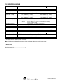
1
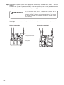
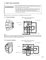
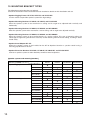
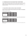
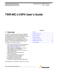
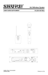
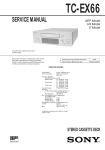
OPERATING INSTRUCTIONS
SPEAKER SYSTEMS
HX-5B
HX-5W
HX-5B-WP
HX-5W-WP
Thank you for purchasing TOA's Speaker
System.
Please carefully follow the instructions in this
manual to ensure long, trouble-free use of
your equipment.
TABLE OF CONTENTS
1. SAFETY PRECAUTIONS ............................. 2
2. GENERAL DESCRIPTION ........................... 3
3. FEATURES ................................................... 3
4. ABOUT THE INPUT OVERLOAD
PROTECTION CIRCUITRY .......................... 4
9. CHANGING THE SPEAKER'S
DIRECTIVITY ANGLE ................................ 7
10. SUSPENDED INSTALLATION .................. 9
11. DIRECT WALL MOUNTING ..................... 13
12. MOUNTING BRACKET TYPES ............... 14
5. INSTALLATION PRECAUTIONS
FOR THE HX-5B-WP AND HX-5W-WP ....... 4
13. COMBINATION WITH THE MT-200
MATCHING TRANSFORMER .................. 15
6. DIMENSIONAL DIAGRAM ........................... 5
14. EQUALIZATION USING
A DIGITAL SIGNAL PROCESSOR ......... 15
7. CHANGING THE ORIENTATION OF
REAR PLATE ............................................... 5
8. INPUT SECTION .......................................... 6
15. SPECIFICATIONS .................................... 16
1. SAFETY PRECAUTIONS
• Before installation or use, be sure to carefully read all the instructions in this section for correct and safe
operation.
• Be sure to follow all the precautionary instructions in this section, which contain important warnings and/or
cautions regarding safety.
• After reading, keep this manual handy for future reference.
Safety Symbol and Message Conventions
Safety symbols and messages described below are used in this manual to prevent bodily injury and property
damage which could result from mishandling. Before operating your product, read this manual first and
understand the safety symbols and messages so you are thoroughly aware of the potential safety hazards.
WARNING
Indicates a potentially hazardous situation which, if mishandled, could
result in death or serious personal injury.
When Installing the Unit
• Refer all installation work to the dealer from whom the speaker was purchased. Installation for flying requires
extensive technical knowledge and experience. The speaker may fall off if incorrectly installed, resulting in
possible personal injury.
• Flying Precautions
Be sure to follow the instructions below. Otherwise, the suspension wires or belts may be off or snap and
the speaker may fall off, causing personal injury.
· Check to confirm that the suspension wires and belts are strong enough to withstand the speaker load.
· The connectors of the suspension wires and belts must be securely linked with those of the speaker.
· All parts and components (such as enclosures, metal pieces, and screws) must be free from any
deformation, crack, and corrosion.
· Be sure to use screws supplied with the optional flying hardware when installing the speaker using such
hardware.
• Install the unit only in a location that can structurally support the weight of the unit and the mounting bracket.
Doing otherwise may result in the unit falling down and causing personal injury and/or property damage.
• (HX-5B-WP and HX-5W-WP only)
When installing the unit in the snowy area, take appropriate measures to prevent snow from lying on the
unit. If the snow lies on the unit, the unit may fall, causing personal injuries.
• (HX-5B and HX-5W only)
Since the unit is designed for indoor use, do not install it outdoors. If installed outdoors, the aging of parts
causes the unit to fall off, resulting in personal injury.
• Owing to the unit's size and weight, be sure that at least two persons are available to install the unit. Failure
to do so could result in personal injury.
• Do not use other methods than specified to mount the bracket. Extreme force is applied to the unit and the
unit could fall off, possibly resulting in personal injuries.
• Use nuts and bolts that are appropriate for the ceiling's or wall's structure and composition. Failure to do so
may cause the speaker to fall, resulting in material damage and possible personal injury.
• Tighten each nut and bolt securely. Ensure that the bracket has no loose joints after installation to prevent
accidents that could result in personal injury.
• Do not mount the unit in locations exposed to constant vibration. The mounting bracket can be damaged by
excessive vibration, potentially causing the unit to fall, which could result in personal injury.
2
CAUTION
Indicates a potentially hazardous situation which, if mishandled, could
result in moderate or minor personal injury, and/or property damage.
When Installing the Unit
• Avoid touching the unit's sharp metal edge to prevent injury.
• To avoid electric shocks, be sure to switch off the unit's power when connecting speakers.
When the Unit is in Use
• Do not place heavy objects on the unit as this may cause it to fall or break which may result in personal
injury and/or property damage. In addition, the object itself may fall off and cause injury and/or damage.
• Do not operate the unit for an extended period of time with the sound distorting. This is an indication of a
malfunction, which in turn can cause heat to generate and result in a fire.
• Do not stand or sit on, nor hang down from the unit as this may cause it to fall down or drop, resulting in
personal injury and/or property damage.
• Have the unit checked periodically by the shop from where it was purchased. Failure to do so may result in
corrosion or damage to the unit or its mounting bracket that could cause the unit to fall, possibly causing
personal injury.
2. GENERAL DESCRIPTION
The TOA HX-5 series is a 2-way compact speaker system that permits both constant directivity control over a
wide frequency range and changes in directivity. It is ideal for reproducing clear sound in spaces with long
reverberation times or high background noises. The HX-5B and HX-5W are designed for indoor use, while the
HX-5B-WP and HX-5W-WP are for outdoor use.
3. FEATURES
• Four speaker modules ensure high power and high quality.
• The changeable orientation of each of the four speaker modules independently allows the directivity angle of
the speaker system to be adjusted.
• Built-in passive network ensures appropriate sound quality.
• Ideal for both permanent and temporary installations, including both vertical and horizontal positioning.
• Equipped with a convenient carrying handle.
• Can be mounted directly on a wall or suspended by wire, chain or shackle with no need to use optional
brackets.
• Optional mounting brackets allow use in a wide variety of applications, including suspension, ceiling
mounting, wall mounting, and speaker stand mounting. Mounting procedures are described in the instruction
manuals enclosed with the mounting bracket or stand adapter.
3
4. ABOUT THE INPUT OVERLOAD PROTECTION CIRCUITRY
The speaker system features internal input overload protection circuitry. If an extremely high input level is fed
to the unit, the protection circuitry automatically cuts off the signal to the tweeters.
A drastic reduction in sound volume for the high frequency range indicates that the protection circuitry has
been enabled.
In such cases, simply reduce the amplifier volume. The protection circuitry will automatically reset in
approximately 10 seconds. After reset, try to maintain the volume at a level slightly lower than before.
Caution
This protection circuitry does not completely protect the unit against extremely high input power levels.
Depending on the type or duration of excessive power input, the protection circuitry might not be enabled,
resulting in damage to the speaker element. Also, if the excessive power input continues for a long period of
time, the circuitry may not be capable of resetting to its original condition.
Use the system with care so that the speakers are not exposed to excessive power input.
5. INSTALLATION PRECAUTIONS FOR THE HX-5B-WP AND HX-5W-WP
Only the HX-5B-WP and HX-5W-WP are suitable for outdoor installation.
For outdoor installation, observe the following precautions.
• All speaker modules must point downward from the horizontal. Failure to do so could adversely affect their
intended weather-resistant capability, leading to malfunction.
[Vertical installation]
[Horizontal installation]
Horizontal
Horizontal
Tilt down from the horizontal.
Tilt down from the horizontal.
• Both the HX-5B-WP and the HX-5W-WP employ a splash-proof construction that allows them to be installed
outdoors, but they should only be installed in locations where the ambient temperature is within the range of
–15°C to +50°C. Exceeding the temperature range will cause the speaker to fail.
4
6. DIMENSIONAL DIAGRAM
Figures show the HX-5 series speaker system with a directivity angle set to 60° mode (factory-preset).
[Top]
• HX-5B/5W Input Section
• HX-5B-WP/5W-WP Input Section
Screw terminals
Speaker cable
(60 cm or 23 5/8 in. long)
Speakon
NL4MP connector
[Front]
[Side]
Input section
342 (13 15/32)
546 (21 1/2)
408 (16 1/16)
[Rear]
Rear plate
Unit: mm (inches)
7. CHANGING THE ORIENTATION OF REAR PLATE
The orientation of the speaker system's rear plate can be changed as follows.
[Factory-preset mounting]
Rear plate
Rear plate
5
8. INPUT SECTION
8.1. HX-5B and HX-5W
• The 2 Speakon connectors are internally connected in parallel to the screw terminals; you can use either
one.
• The right table shows the pin arrangement of the
Speakon NL4MP connector.
Pin No.
1 +
1 –
2 +
2 –
HX-5B, HX-5W
Speaker +
Speaker –
–
–
• The usable connector (on the cable end) for the Speakon NL4MP is Speakon NL4FC.
• Wiring diagram of the input connectors is shown at right.
Screw terminal 2P
–
+
Speaker +
Speaker –
1+
1+
2–
2–
1–
1–
2+
• Two speaker systems can be operated in parallel by
connecting them in a cascade configuration as shown at
right.
2+
First speaker
Note
Be sure to connect the speaker system to the power
amplifier's output terminal of 4 Ω or less.
Connecting it to an output terminal of over 4 Ω may
cause amplifier failure.
8.2. HX-5B-WP and HX-5W-WP
[Rear]
Black
(+)
6
White
(–)
Speakon NL4MP x 2
Second speaker
9. CHANGING THE SPEAKER'S DIRECTIVITY ANGLE
The speaker system's directivity angle mode is factory-preset to 60°,
but this mode can be changed to 45°, 30°, or 15° by following the
procedure described below.
The figure on the right shows the speaker system in 60° mode.
directivity angle
60°
Step 1. Loosen the 2 bolts on the input section side.
Input section
Step 2. Turn the speaker system upside down. Then, loosen the 4 bolts indicated by arrows.
7
Step 3. Reposition the 4 bolts to the desired directivity angle, then retighten them securely.
The sound coverage area can also be made asymmetrical by shifting the position of each bolt to
different directivity angle.
[60° mode (factory-preset)]
15° mode
Angle adjustment section
Example of independent
angle adjustment
30° mode
15° mode
45° mode
60° mode
Step 4. Reposition the speaker system by turning it upside down. Then, tighten the 2 bolts loosened in step 1.
WARNING
8
Observe the following instructions to tighten the bolts securely.
Failure to do this could cause the speaker to fall, potentially
resulting in damage and/or personal injury.
• Ensure that each bolt is correctly inserted into its slot before
tightening it.
• Bolts can be tightened using either a Phillips screwdriver or a
wrench, but be sure to finish the tightening with the wrench to
ensure optimum tightness.
10. SUSPENDED INSTALLATION
The speaker systems may be suspended either vertically or horizontally.
[Vertical suspension]
Step 1. For vertical suspension:
[Horizontal suspension]
Remove the speaker grill on the module to be suspended. (Below, upper)
For horizontal suspension: Remove the speaker grills on the modules at both ends of the speaker
system. (Below, lower)
Remove the grill fixing screws using the supplied hex head wrench.
Speaker grill
Grill fixing screw
[Vertical suspension]
Speaker module
[Horizontal suspension]
9
Step 2. For vertical suspension:
Remove the 2 front bar fixing bolts. (Below, upper)
For horizontal suspension: Remove the 4 front bar fixing bolts. (Below, lower)
Place the speaker system on a workbench when doing this work.
Front bar fixing bolts
[Vertical suspension]
Front bar
[Horizontal suspension]
10
Step 3. Fix the suspension bracket and the front bar with the bolts removed in step 2.
WARNING
Observe the following instructions to tighten the bolts securely.
Failure to do this could cause the speaker to fall, potentially
resulting in damage and/or personal injury.
• Ensure that each bolt is correctly inserted into its slot before
tightening it.
• Bolts can be tightened using either a Phillips screwdriver or a
wrench, but be sure to finish the tightening with the wrench to
ensure optimum tightness.
Suspension bracket
(supplied)
Front bar
The figure on the right is for the
horizontal suspension of speaker system.
For the vertical suspension, the work is
done on either module to be suspended.
Step 4. For vertical suspension: Turn the speaker system upside down. Then, mount the suspension bracket
in the same manner as described in steps 2 and 3.
Suspension bracket (supplied)
Step 5. Replace the removed speaker grill.
Be sure to use the supplied hex head wrench to tighten the fixing screws.
Speaker grill
Ensure that the sponge is fitted in the slot.
Punched grill
Sponge
Speaker
11
Step 6. Suspend the speaker system using appropriate commercially obtained wires, chains, or anchor
shackles.
To mount the speaker system horizontally, rotate the speaker system's rear plate 90° from the
factory-preset orientation. For details, refer to p. 5, Changing the orientation of rear plate.
WARNING
Be sure to select wires, chains, and/or anchor shackles with a
safety factor appropriate to the weight of the speaker system.
Incorrect selection of these suspension components may cause
the speaker system to fall, potentially resulting in damage and/or
personal injury.
Run the anchor shackles, etc. through the holes in the 2 suspension brackets and rear plate as shown
in the figure.
[Vertical suspension]
[Horizontal suspension]
Anchor shackle
Suspension bracket
Rear plate
12
11. DIRECT WALL MOUNTING
WARNING
Observe the following instructions when mounting the speakers on a wall.
Doing otherwise may cause the speaker system to fall, potentially
resulting in damage and/or personal injury.
• Use anchor bolts, nuts, and washers with specifications appropriate for
carrying the load of the speaker system. Also ensure that the structure
of the wall is robust enough to stand the weight of the speaker.
• Take measures to prevent nuts and bolts from loosening and sliding out
of their positions as required.
Note: Anchor bolts, nuts, and washers are not supplied with the speaker system.
11.1. Vertical Installation
[Direct wall mounting dimensions]
(Angle mode of 60°)
Unit: mm (inches)
408 (16 1/16)
Speaker system
23 (29/32)
131 (5 5/32)
546 (21 1/2)
6 (15/64)
181 (7 1/8)
Rear plate
4-12 x 41 (4-15/32 x 1 39/64)
Note
For outdoor use, install the HX-5B-WP or HX-5W-WP in conjunction with the HY-WM1WP Speaker Mounting
Bracket so that all speaker modules point downward from the horizontal. Failure to do so could adversely
affect their water-resistant capability, leading to malfunction.
11.2. Horizontal Installation
[Direct wall mounting dimensions]
(Angle mode of 60°)
Unit: mm (inches)
546 (21 1/2)
Rear plate
Speaker system
181 (7 1/8)
408 (16 1/16)
23 (29/32)
131
(5 5/32)
6 (15/64)
4-12 x 41 (4-15/32 x 1 39/64)
13
12. MOUNTING BRACKET TYPES
The following mounting brackets are optional.
Consult the instruction manual enclosed with each bracket for details on their installation and use.
• Speaker Rigging Frames HY-PF1B, HYPF1W, and HY-PF1WP
Can be used to suspend the speaker system from high ceilings.
• Speaker Mounting Brackets HY-CW1B, HY-CW1W, and HY-CW1WP
Allow the speaker system to be mounted to a ceiling and its angle to be adjusted both vertically and
horizontally.
• Speaker Mounting Brackets HY-WM1B, HY-WM1W, and HY-WM1WP
Allow the speaker system to be mounted to a wall or ceiling and its angle to be adjusted vertically.
• Speaker Mounting Brackets HY-WM2B, HY-WM2W, and HY-WM2WP
Allow the speaker system to be mounted closely to a wall or ceiling. This type of mounting offers the
advantage of suppressing interference caused by sound reflecting from the wall or ceiling, resulting in better
sound clarity.
• Speaker Stand Adapter HY-ST1
Allows the speaker system to be installed on the ST-32 Speaker Stand or a speaker stand having a
mounting pipe diameter of 35 mm.
• Speaker Extension Brackets HY-CN1B, HY-CN1W, HY-CN1B-WP, and HY-CN1W-WP
Connect 2 speaker systems to allow directivity control for lower frequencies.
[Speaker systems and mounting brackets]
Mounting bracket
Speaker rigging frames
Speaker system
HY-PF1B
HY-PF1W
HY-PF1WP
Speaker mounting brackets
HY-CW1B
HY-CW1W
HY-CW1WP
Speaker mounting brackets
HY-WM1B
HY-WM1W
HY-WM1WP
HY-WM2B
HY-WM2W
HY-WM2WP
Speaker stand adapter
HY-ST1
Speaker Extension brackets
HY-CN1B
HY-CN1W
HY-CN1B-WP
HY-CN1W-WP
14
HX-5B
HX-5W
HX-5B-WP
HX-5W-WP
13. COMBINATION WITH THE MT-200 MATCHING TRANSFORMER
Using the optional MT-200 matching transformer allows the speaker system to be connected to a highimpedance amplifier. This matching transformer is best for use when the distance between the amplifier and
speaker is very long, or when multiple speaker systems are parallel-connected to a single amplifier.
Regarding the procedure for mounting the transformer on the speaker, refer to the instruction manual
enclosed with the MT-200.
14. EQUALIZATION USING A DIGITAL SIGNAL PROCESSOR
The speaker systems are to reproduce wide-band, high-efficiency sound even without the use of an equalizer.
However, sound quality can be made even clearer and more dynamic with the addition of a TOA digital signal
processor set as shown in the table.
[Filter characteristics for normal mode]
Filter
HPF (12 dB/oct)
PEQ
Frequency
60 Hz
65 Hz
800 Hz
2.5 kHz
5 kHz
Gain
–
+2 dB
–3 dB
–4 dB
+5 dB
Q
2.053
1.414
0.7
2.997
0.305
[Filter characteristics for low-frequency cut mode (speech applications) or when used with the FB-120
series Subwoofer System]
Filter
HPF BW (24 dB/oct)
PEQ
Frequency
90 Hz
800 Hz
2.5 kHz
5 kHz
Gain
–
–3 dB
–4 dB
+5 dB
Q
–
0.7
2.997
0.305
Note
When using the processor with the HX-5 series and the FB-120 series, ensure that the wiring polarity of both
units is the same.
15
15. SPECIFICATIONS
Model No.
Enclosure
Power Handling Capacity
HX-5B
HX-5W
Bass-reflex type
Frequency Response
(Deviation –10 dB)
Sealed type
8Ω
96 dB (60° mode), 97 dB (45° mode), 98 dB (30° mode), 99 dB (15° mode)
70 to 20,000 Hz (60° mode)
75 to 20,000 Hz (45° mode)
80 to 20,000 Hz (30° mode)
85 to 20,000 Hz (15° mode)
Crossover Frequency
Directivity Angle
HX-5W-WP
Continuous pink noise: 200 W, Continuous program: 600 W
Rated Impedance
Sensitivity (1 W, 1m)
HX-5B-WP
95 to 20,000 Hz (60° mode)
100 to 20,000 Hz (45° mode)
105 to 20,000 Hz (30° mode)
110 to 20,000 Hz (15° mode)
4 kHz
Horizontal: 100° (over 2,000 Hz)
Vertical:
60° (over 800 Hz), 45° (over 1.2 kHz), 30° (over 1.6 kHz),
15° (over 3.2 kHz) variable
Speaker Component
Low frequency: 12 cm (5") cone-type x 4
High frequency: Balanced dome-type x 12
Input Terminal
Speakon NL4MP x 2 and M4 screw terminal
–
Speaker Cord
–
2-core cabtyre cord with diameter of 6 mm
or 15/64 in. (60 cm or 23 5/8 in. long)
Water Protection
–
IPX4*
Operating Temperature
–
–15°C to +50°C
Finish (Enclosure)
Polypropylene, black
Dimensions
Weight
Polypropylene, white
Polypropylene, black
Polypropylene, white
408 (w) x 546 (h) x 342 (d) mm
16 1/16 (w) x 21 1/2 (h) x 13 15/32 (d) inches
16 kg
* Install with the every speaker module downward.
Note: The design and specifications are subject to change without notice for improvement.
• Accessories
Suspension bracket .................................... 2
Hex head wrench ....................................... 1
Printed in Indonesia
533-06-125-50