1
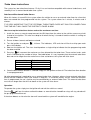
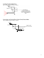
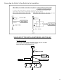
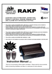
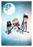
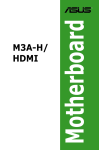
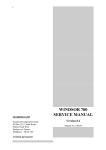
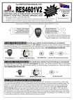
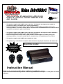
Proudly Designed
In Australia
AUSTRALIAN STANDARDS APPROVED
REMOTE CONTROL ENGINE IMMOBILISER
AND AL ARM .
•
•
•
•
N517
This product complies with AS/NZS 3749.1 2003 Class A. Volumetric Sensing must be enabled to
comply with a Class A installation (refer ‘feature programming’).
Class A VSAS (Vehicle security alarm system) includes control equipment including setting and
unsetting facilities, all sensors, warning devices and provisions for immobilization of the vehicle and the
volumetric sensing device (glass break/shock).
This product complies with AS/NZS 3749.1 2003 Class B. Volumetric Sensing must remain disabled to
comply with a Class B installation (refer ‘feature programming’).
Class B VSAS (Vehicle security alarm system) includes control equipment including setting and
unsetting facilities, all sensors, warning devices and provisions for immobilization of the vehicle.
•
This product complies with AS/NZS 4601:1999/Amdt 1: 2003
•
This product is to be installed in accordance with the methods & principles detailed in AS 3749.2:1997
Has your insurer
specified fitting a
“RES2001”?
For details, please
refer to page 13
Override code:
Instruction Manual
Thank you for purchasing a Rhino Alarm and Engine Immobilisation system.
Please read this manual carefully before commencing installation and keep it in a safe place for future
reference.
1
Contents
System Features .....................................................................................................................................................3
Standard System Features ..............................................................................................................................................3
Selectable System Features............................................................................................................................................3
Optional Accessories .......................................................................................................................................................3
Detailed Feature Descriptions...................................................................................................................................4
Automatic Immobilisation.................................................................................................................................................4
Automatic re-arm & relock (Programmable) ....................................................................................................................4
Door Ajar Warning (Programmable) ................................................................................................................................4
Timed Headlight Delay (Optional connection by installer at extra cost)..........................................................................4
Perimeter Night Light (Programmable)............................................................................................................................4
Dome Light Extension (Programmable) ..........................................................................................................................4
Glass Break Sensor.........................................................................................................................................................4
Door Lock on Ignition (Programmable)............................................................................................................................5
Pre-Alert (2 Stage) Car Body Impact Warning with ETS™ .............................................................................................5
Auto Bypass.....................................................................................................................................................................5
Alarm Operation ................................................................................................................................................... 6
Remote Control Functions:.......................................................................................................................................6
Activate Panic or Car Finder Function.............................................................................................................................7
Remote Boot (Trunk) Release.........................................................................................................................................7
Programming Additional Remote Controls / Erasing Lost Remote Controls...................................................................7
Overriding the Immobiliser ......................................................................................................................................7
Overriding the Immobiliser ......................................................................................................................................8
Programming ..........................................................................................................................................................8
How to Program the Selectable Features: ......................................................................................................................8
Detailed Example:............................................................................................................................................................9
How to Change REGISTER 1: ........................................................................................................................................9
How to Change REGISTER 2: ......................................................................................................................................12
Installation ............................................................................................................................................................13
“RES2001” Insurance Requirements.............................................................................................................................13
Installing the Main Control Unit......................................................................................................................................13
Internal Connector Diagram ..........................................................................................................................................13
Factory Remote Interface ......................................................................................................................................14
Modes of Operation: ......................................................................................................................................................14
Inhibit mode (Register 1 Feature 10): .................................................................14
Enable mode (Register 1, Feature 10): ...............................................................15
Learn Mode (Register 1, Feature 9):...................................................................15
Turbo timer instructions.........................................................................................................................................16
Interface with external turbo timers ...............................................................................................................................16
On-board turbo timer .....................................................................................................................................................17
WIRING INFORMATION .......................................................................................................................................18
Installing the Coded Battery Backup Siren (BBSC / MiniBBSC): ..................................................................................20
Installing Additional Sirens (non-coded) ........................................................................................................................20
Installing Timed Headlight Delay ...................................................................................................................................21
Connecting to an Existing Electric Boot (Trunk) Release Motor ...................................................................................21
Central Door Lock Diagrams .........................................................................................................................................23
WARRANTY TERMS & CONDITIONS .........................................................................................................................25
2
System Features
Standard System Features
•
•
•
•
•
•
•
•
•
•
•
•
•
•
•
•
Microprocessor Controlled
Three Point Engine Immobilisation (Onboard Relays)
Auto Immobilise (Passive Arming)
Code Hopping Remote Technology (Anti-Scanning, Anti-Code Grabbing)
Two SSR™ Solid State Remote Controls with 4 Function Operation (Arm / Disarm, Boot Release, Panic)
Long Life Lithium Cell Remote Control Batteries (Each Remote Uses 2 x CR2025)
Automatic Re-arm in case of Accidental Disarm
Ultra-Bright Red Flashing LED Light
Visual Arming and Disarming via Indicators (1 Flash For On, 2 Flashes For Off)
Safety Circuit Prevents Arming While Ignition On
Learning Mode for Adding Additional Remote Controls (maximum of 5)
Negative On Alarm Output for Optional Internal Cabin Siren
Onboard Central Locking Relay Outputs
All points of entry alarm protection (doors, boot, bonnet)
Personal panic button via remote control (siren sounds & indicators flash)
Auto Bypass (prevents false alarms caused by faulty sensors / or switches)
Selectable System Features
•
•
•
•
•
•
•
•
•
•
•
•
•
•
•
Arm / disarm beeps (if optional siren fitted)
Door ajar warning (indicators flash & siren (if fitted) beeps for 3 seconds if a door is left ajar i.e. Vehicle’s interior
light circuit sees door in open position)
Electric boot release output via remote control – no delay (standard feature is to hold button for 3 seconds)
Timed headlight delay (optional feature at additional installation cost)
Multiple vehicle remote control (control 2 cars separately from the 1 remote)
Central closure (allows electric window / sunroof closure on arming of some vehicles)
Door lock on ignition (anti hi-jack)
Perimeter night light (indicators hold on for 20 seconds on disarm)
Dome Light Extension (interior light turns on for 20 seconds on disarm)
User programmable override code in case of loss or damage of remotes (over 63,000 possible codes)
Compatible with Transformer interface for vehicles with factory keyless entry systems. Allows for factory remote
controls to arm/disarm the system.
Compatible with Wireless Keypad to allow arm/disarm of the system without remote controls.
In-built 2 stage pre-alert car body impact sensor with ETS™
Audio discriminating glass break sensor
Alarm memory (allows recall of the10 most recent alarm activations in order)
Optional Accessories
•
•
•
•
•
•
Internal Cabin Siren
Ultrasonic Sensors
Microwave Sensor
Electronic Tilt Sensor
Paging System
Wireless Keypad
(Part No: DPS)
(Part No: UD6)
(Part No: UD5)
(Part No: TILTSENSE2)
(Part No: APAGER)
(Part No: WKPB)
3
Detailed Feature Descriptions
Automatic Immobilisation
The immobiliser will automatically activate 38 seconds after the ignition is switched off - This is indicated via the dash
mounted LED, which will illuminate to confirm the system has entered auto immobilise mode. During this time the vehicle
cannot be started until a valid remote has disarmed the system. After disarming, if the ignition is not switched on before
38 seconds have elapsed, the alarm will again go into auto immobilise mode.
Automatic re-arm & relock (Programmable)
This feature prevents accidental disarming by the owner i.e. the owner turns the immobiliser off but is then distracted and
forgets that they have deactivated the system. If a door is not opened or ignition turned on within 60 seconds from when
the system is turned off by the remote, the system will fully re-arm & re-lock the vehicle.
Note: The immobiliser will enter auto immobilise mode after 38 seconds (the LED will come on constantly to indicate the
vehicle is immobilised). At the 60-second mark, the system will fully arm & the doors will lock – the blinkers will flash once
& the siren will beep once & the LED will start flashing.
Door Ajar Warning (Programmable)
If the vehicles doors are not properly closed when you try to activate your immobiliser system, the indicators will flash and
the siren will beep for 3 seconds to alert you that the vehicle is not secure.
Timed Headlight Delay (Optional connection by installer at extra cost)
You can have your car headlights turn on automatically for 15 seconds when you arm the immobiliser by remote control.
This may allow you for instance to see your way to your front door, or out of a dark car park. You can turn the lights off
before the 15-second period ends by pressing the left button on your remote.
Perimeter Night Light (Programmable)
When this feature is on, the indicators will stay on constantly for 20 seconds on disarm, or until the ignition is turned on.
This allows for illumination around the vehicle at night.
Dome Light Extension (Programmable)
The dome (interior) light comes on automatically when the system is disarmed via remote, enabling the owner to verify
the vehicle is safe inside. The light stays on for 20 seconds, or until the ignition is turned on. The dome (interior) light also
comes on automatically when the ignition is turned off, enabling the owner to quickly gather belongings before exiting the
car. The light stays on for 20 seconds, or until the system is armed via remote, or until the ignition is turned on again.
NOTE: If you activate the Automatic Rearm & Relock Feature, this feature will be disabled.
Glass Break Sensor
The Jagv2/Rav3 with the addition of a special cabin microphone incorporates intelligent glass break sensing circuitry.
This inbuilt device will trigger the alarm system, provided it registers the correct sound frequency parameters for breaking
glass & that the impact sensor also registers a corresponding vibration to the vehicle. This ensures accurate detection of
glass breakage.
4
Door Lock on Ignition (Programmable)
If you have central locking connected, when this feature is on the doors will lock when the ignition is turned to on, and
unlock when the ignition is turned to off. This is to prevent anyone but occupants in the vehicle from being able to open
the doors.
Pre-Alert (2 Stage) Car Body Impact Warning with ETS™
This special feature provides a two-stage impact sensing system. It gives the security conscious owner a sensitive car
body impact sensor that will give a potential thief prior warning that the vehicle is protected by this most formidable alarm
system. On detection of a low level impact i.e. from a tyre kick, the siren will simply beep for a few seconds to warn away
the would-be thief. If the vehicle is attacked any further, the system will move into full siren mode. The unique ETS™
Environment Tuned Sensor is able to distinguish between environmental shocks caused by aircraft, trucks, or extreme
weather conditions, and the impact caused by any thief attempting to break in or other heavy impacts. Furthermore the
system features the unique Rhino "Auto Adjust” process, where during the 45 sec. arming delay, the alarm samples the
background noise where the vehicle is parked, and will if necessary automatically reduce the sensitivity of the impact
sensor to an appropriate level. This process allows a trouble free sensitivity that ordinary alarms simply cannot provide.
The sensitivity level reference point can be adjusted to suit your particular needs. Please refer to the programming
section contained later in this manual.
Auto Bypass
Auto bypass is designed to reduce false alarms caused by faulty switches or external sensors. If the alarm is triggered 3
times by the same sector then the particular sector will be bypassed. (i.e. the sector will become inactive.) The sector will
only be bypassed for one arming period. The next time the system is armed the sector that was bypassed will again
become active.
5
Alarm Operation
Remote Control Functions:
Remote Control Symbols
⁄
Action on Alarm
Arm/Disarm the Alarm System
Hold for Boot Release
Alarm Panic Mode
Optional
Optional 4th Channel for Home Alarm
6
Arming and Disarming Your Immobilizer
TO ARM YOUR IMMOBILISER (& lock your vehicle if central locking is connected)
Pressing the ⁄
button on the remote control transmitter activates the immobiliser. The blinkers will flash
once and the siren will beep once. For silent arm / disarm press ⁄
and
both buttons If central
locking is connected, your doors will lock. The dash LED-light will stay on for 20 seconds then flash, THE
IMMOBILISER IS NOW ON.
…
LED COMES ON……….and after 20 seconds starts to flash.
Press
⁄
button
Blinkers will flash once
TO DISARM YOUR IMMOBILISER (& unlock your vehicle if central locking is connected)
To deactivate the immobiliser, press the ⁄
button. The blinkers will flash twice and the siren will beep
twice. The LED will stop flashing. If central locking is connected, your doors will unlock. THE IMMOBILISER
IS NOW OFF. Note: If the alarm has been activated in your absence, the siren will beep 4 times on disarm.
Activate Panic or Car Finder Function
…
Press
⁄
Pre
Button
Blinkers will flash Twice
LED Switches OFF
EMERGENCY PANIC / CAR FINDER FUNCTION
The panic / car finder feature is activated by pressing the
button on the remote control transmitter for 3
seconds. This causes the indicators to flash (i.e. same as hazard lights) and the siren to sound. To cancel
“panic”, press the
button on the transmitter for 3 seconds again.
Note: Panic will not activate while the ignition is on by requirement of Australian Law (DECC).
Remote Boot (Trunk) Release
BOOT (TRUNK) RELEASE (Optional connection by installer at extra cost)
This immobiliser is fitted with remote boot (trunk) release capability for vehicles with existing electric boot
(trunk) release. This feature enables the user to unlock the boot (trunk) by pressing the
button for 3
seconds. The boot will unlock, and the immobiliser will disarm. NOTE: For safety reasons the remote boot
(trunk) release will not work when the ignition is on.
Note: Boot release can be programmed to trigger instantly on pressing the
button.
Programming Additional Remote Controls / Erasing Lost Remote Controls
Your Jagv2/RAv3 is supplied standard with 2 remote controls - Up to a maximum of 5 remotes can be used. To add a
new remote to your alarm, simply follow the procedure below:
1. Turn the vehicle’s ignition to on.
2. Immediately press and hold the /
button on the original remote control until the indicators start
to flash (approximately 4 seconds) and then release the button.
3. Immediately press and hold the /
button on the new remote control for at least 4 seconds.
4. Turn the vehicle’s ignition off.
5. The new remote control is now programmed into the immobiliser.
Erasing Lost Remote Controls: If you lose a remote control or perhaps have your car keys stolen, you can
simply erase the lost/stolen remotes by repeating the procedure above 10 times. This will fill the system memory with
remotes that only you have in your possession.
Overriding
the Immobiliser
Learning in a new remote when no working remote is available:
You may learn in a remote without having an already learnt-in remote. Please see “Overriding the Immobiliser” for more
7
information.
Overriding the Immobiliser
PROCEDURE:
Your alarm has been loaded with a randomly generated 5 digit override code. This feature enables the
owner to override their immobiliser and start the vehicle in the case of lost or damaged remote controls.
The customer must be made aware of this code, which is placed, on the front of this manual and
the supplied override code card.
To enter your override code:
1. Enter the vehicle. If the alarm is armed the siren will sound - this may be turned off using your siren
key but will not affect the procedure.
2. Ensure that the bonnet and boot are shut, your vehicles doors may be open or closed.
3. Turn the ignition from ON to OFF in a quick steady rhythm an equal number of times to the first PIN
digit
4. Wait for the indicators to flash once. If the alarm is armed you will not be able to see the flash,
instead watch for a flash on the red dash LED
5. Repeat steps 3 and 4 for the second PIN digit, remembering to wait to see the indicators or dash
LED flash.
6. Repeat until all five PIN digits have been entered.
7. If the code has been entered correctly, the alarm will disarm. Start the vehicle within 38
seconds or the alarm will automatically immobilise and the procedure will need to be repeated.
If you make a mistake during code entry and the alarm does not disarm, please wait at least
one minute before trying again.
Note: This procedure will have to be repeated each time you wish to start the vehicle without a
working remote. To learn in a new remote when all remotes have been lost, repeat the above
procedure with the door and the bonnet open. After the final pin digit has been entered the indicators
button on the new remote control twice and hold this
will begin to flash - Immediately press the /
button on the second press for three seconds. The new remote should now be learnt to the system.
Programming
Your Rhino Security system incorporates the latest in high security & convenience features. It is possible to
customise your security system so that it suits your requirements perfectly. Detailed below is the full list of
programmable features that can either be turned on or turned off.
We have factory set the most common configurations as listed in the REGISTER settings below. Once the
desired features have been selected, the selection is permanently retained in memory, even if power is
removed.
How to Program the Selectable Features:
1. By referring to pages 10 – 13 of this manual, find the REGISTER in which the desired feature to be
programmed is located. That is, REGISTER 1 or REGISTER 2.
For example, to program the ‘Door Lock on Ignition’ feature, see REGISTER 1.
2. Set the vehicle up as described to access the appropriate REGISTER.
Taking the same example from Step 1: the ‘Door Lock on Ignition’ feature is in REGISTER 1. The appropriate vehicle
setup for REGISTER 1 is – all doors closed. The appropriate vehicle setup for REGISTER 2 is – driver’s door open.
3. Arm then disarm the alarm using
⁄
. Then, switch the ignition on, then off, then on again. Now the
feature is ready to be programmed using
of the remote.
4. Within 3 seconds, begin to press
an equal number of times to the selected feature code. Each press of
the remote will be confirmed by a flash of both the indicators and the dash LED; a confirmation beep will also
be produced.
8
Following the previous example, programming the ‘Door Lock on Ignition’ feature requires three presses of
This will change the setting of the feature from OFF (factory default) to ON.
.
5. Turn the ignition to off.
6. The system will then confirm if the feature has been set to ON or OFF. One beep will be produced from
the siren if the selected feature has been turned ON. Two beeps will be produced from the siren if the feature
has been turned OFF.
Detailed Example:
To program the ‘Door Lock on Ignition’ Feature (REGISTER 1; Feature 3):
1. Ensure that the vehicle’s doors are closed and the ignition is switched off.
2. Arm and then immediately disarm the alarm.
3. Turn the ignition to ON.
4. Within 3 seconds, turn the ignition OFF.
5. Within 3 seconds, turn the ignition to ON.
6. Within 3 seconds, press
three times.
7. Turn the ignition OFF.
8. The feature has now been set. You will now hear 1 confirmation beep for ON or 2 confirmation beeps for OFF.
How to Change REGISTER 1:
Vehicle Set Up: ALL DOORS CLOSED AND IGNITION ON → OFF → ON
Remote Key action: TURN ON / OFF FEATURES VIA THE
BUTTON ON THE REMOTE
FEATURE
Arming & Disarming Beeps
Door Lock on Ignition
(Anti-Hijack)
No Door Ajar Warning
Press
Remote
This Many
Times
2
3
FACTORY
SETTING
DESCRIPTION
ON
OFF
1 beep on Arm & 2 beeps on Disarm.
When this feature is on, the doors will lock when the ignition
is turned to on, and unlock when the ignition is turned to off.
When this feature is on, the door ajar warning feature is
removed (the siren & indicators will not beep & flash for 3
sec. if a door is not closed properly).
When this feature is on, the indicators will stay on constantly
for 20 seconds on disarm, or until the ignition is turned on.
This allows for illumination around the vehicle at night.
When this feature is on, the boot release button (Left
Button) will only require be pressing once rather than
holding down for 3 seconds to open an electric boot.
The dome (interior) light comes on automatically when the
system is disarmed via remote, enabling the owner to verify
the vehicle is safe inside. The light stays on for 20 seconds,
or until the ignition is turned on. The dome (interior) light
also comes on automatically when the ignition is turned off,
enabling the owner to quickly gather belongings before
exiting the car. The light stays on for 20 seconds, or until the
system is armed via remote, or until the ignition is turned on
again.
4
OFF
Perimeter Night Light
5
OFF
Instant Boot Release
6
OFF
Dome Light Extension
(Interior lights on when
ignition off, interior lights on
when system disarmed via
remote). Note: This feature
cannot be turned on if AutoRearm & Relock is activated.
See register 2.
8
OFF
9
Inhibit / Enable Mode
Selection for Upgrade inputs
10
Inhibit
Inhibit mode – NEG1 and NEG2 become inhibit wires which
stop the upgrade interface from arming/disarming the alarm
i.e. usually connects to the motor switch wires so that when
they open the door with the lock manually it will NOT disarm
the alarm
Enable mode – POS2 input becomes an ‘enable’ wire which
must go positive to allow the upgrade interface to
arm/disarm the system. This is usually connected to the
blinkers, as they will activate when the factor remote is
pressed only.
NOTE: Enable mode POS2 wire in Upgrade Learnt mode
will learn the required state.
Shock Sensor Adjustment
11
6
SELECT
the level
required.
After pressing the remote 11 times to enter this mode, turn
the ignition to off. There are 8 levels of adjustment. The
factory default setting is level 6. Pressing the remote once
will increase the sensitivity by one level i.e. to level 7. The
LED will then flash seven times to confirm the new level.
Pressing the remote again will increase the sensitivity to
level 8 (max). Pressing the remote again will return the
adjustment to level 1(least sensitive). Once you have
adjusted the sensitivity level to the desired setting, turn the
ignition on to exit this mode.
Installer Mode
12
SELECT
The Mode
Required
After pressing the remote 12 times to enter this mode, turn
the ignition to off. This mode allows the installer / owner to
verify that each trigger of the alarm system is working,
without having to arm & disarm the system each time & set
off the siren. The siren will beep and the blinkers will flash to
indicate a trigger eg push the bonnet switch, open a door,
hit the vehicle. The siren will beep four times to indicate a
pre-warning impact sensor detection, or once to indicate full
alarm trigger level. Turn the ignition to on to exit this mode.
PAT™ Past Alarm Trigger
Memory
13
SELECT
to replay
memory
After pressing the remote 13 times to enter this mode, turn
the ignition off. Your Rhino Alarm offers a unique memory
that stores the ten last reasons why the alarm was
triggered. This memory cannot be erased.
1 Beep, 1 Flash - Voltage Drop Alarm
2 Beep, 2 Flashes - Glass Break Alarm
3 Beep, 3 Flashes - Shock Sensor Alarm
4 Beep, 4 Flashes - Power Fail Alarm
5 Beep, 5 Flashes - Ignition Alarm
6 Beep, 6 Flashes - Aux Alarm
7 Beep, 7 Flashes - Door Alarms
8 Beep, 8 Flashes - Bonnet / Boot Alarm
If two previous alarms were recorded i.e. voltage drop and
shock sensor the LED will flash and the siren will beep once
for voltage drop, then no noise for 1 second then beep three
times for shock sensor. The last memory heard is the
most recent alarm sector triggered. Turn the ignition to
on to exit this mode.
Current Sense Override
15
ON
When this feature is on, the alarm will not trigger when a
sudden change in battery current is sensed.
NOTE: This will ONLY beeps out the state of this feature i.e.
no other active features in the register will be beeped out.
I.e. if this feature is NOT on, then NO beeps will be heard.
10
Turbo Timer Run Time
16
OFF
This feature is used for setting the run time for both
interface and onboard turbo timers. Refer to Turbo Timer
Instructions.
Onboard Turbo Timer
17
OFF
When turned ON this feature activates the on-board turbo
timer which allows the turbo timer to be shut down early via
button 2. To set up the on board turbo timer, refer to Turbo
Timer Instructions.
3 second Panic Delay /
Instant Panic
18
ON
When this feature is ON button 3 needs to be held for 3
seconds to activate panic.
TransTX Upgrade Mode
(Only required if the old style
OEM enhancement is used)
19
OFF
When this feature is turned on then the Transformer module
may be interfaced to allow the user to arm and disarm their
vehicle via the factory remote control.
If this featured is turned on then a single beep will be
produced. If this feature is turned off then no beeps will be
heard.
Auto Immobilise Override
20
OFF
When this feature is turned ON the vehicle will not auto
immobilise.
Wireless Keypad Mode
21
OFF
When this feature is turned on then the Wireless Keypad
may be used to disarm the vehicle while still using the
standard factory remotes to lock and unlock the vehicle.
See the Wireless Keypad instructions for further details.
If this featured is turned on then a single beep will be
produced. If this feature is turned off then no beeps will be
heard.
Courier mode
22
OFF
When this feature is turned on then the Wireless Keypad
may be used to disarm the vehicle while still using the
standard factory remotes to lock and unlock the vehicle.
See the Wireless Keypad instructions for further details.
If this featured is turned on then a single beep will be
produced. If this feature is turned off then no beeps will be
heard.
11
How to Change REGISTER 2:
Vehicle Set Up: DRIVER’S DOOR OPEN, AND IGNITION ON → OFF → ON
Remote Key action: TURN ON / OFF FEATURES VIA THE
BUTTON ON THE REMOTE
Press
Remote This
Many Times
FACTOR
Y
SETTIN
G
DESCRIPTION
LEFT Button Used To
Arm/Disarm This Vehicle
2
OFF
This is activated if you have two cars with Rhino remote
controls, the vehicle that this is feature is activated on will use
the left button to arm disarm and loose the ability to activate
the boot release output.
Impact Sensor
3
ON
Activate 2 Stage Impact sensor & glass break sensor.
Automatic Rearm & Relock
4
OFF
This feature prevents accidental system disarming & will
relock the doors if a door is not opened within 60 seconds.
See page 2 for full function description. If you activate this
feature, dome light extension will be turned off automatically.
Installers must wire up the door circuit to function.
Timed Negative on Arm
(Headlight Timer – 15 sec)
5
OFF
When on, this feature changes the –ARM wire from being a
constant negative on arm to a timed 15 second negative
on arm wire. This will allow you to connect this wire via a
relay (see diagram on page 15) to your headlight circuit, so
that when you arm your immobiliser, your headlights will turn
on for 15 seconds to illuminate your path, and then
automatically switch off. (You can press the LEFT button on
your remote to turn the lights off before the 15-second
period). You can still connect window lift modules to this wire,
as long as it takes no longer than 15 seconds to wind up the
windows in the car.
Selectable Indicator Flash
6
ON
When off, this feature prevents the indicators from flashing
when the system is triggered.
Extended Lock Pulse (Central
Closure)
7
OFF
When on, the lock output becomes a 15 second negative
pulse instead of 0.5 seconds. This feature is for certain
vehicles with vacuum central locking or those with a central
closure wire (some BMW, Mercedes) i.e. doors lock, electric
windows wind up, sunroof closes automatically.
Extended Unlock Pulse
8
OFF
When on, the unlock output becomes a 15 second negative
pulse instead of 0.5 seconds. This feature is for certain
vehicles with vacuum central locking.
FEATURE
12
Installation
“RES2001” Insurance Requirements
Some Insurance Companies in Australia will now specify that they require a Rhino Model “RES2001” Immobiliser to be
professionally fitted to their client’s vehicles before they will insure the vehicle for theft.
The code RES2001 has been especially given to insurance companies to make sure that their
specified installation of a RAv3 is carried out to their client’s vehicles. If a customer says they need
to have an RES2001 fitted this means that you must:
1. Be qualified to install an automotive security product, and if required hold the necessary security license
(compulsory in NSW).
2. Install the Rhino JAGv2/RAv3 with 3 separate immobilisation points (i.e. starter, fuel, & ignition).
3. Provide your customer with an invoice stating that a “Rhino RES2001” has been installed.
Installing the Main Control Unit
Mount under the dash, in a well-hidden location. Securely fix the main unit with cable ties or similar to
prevent the unit from moving around. Failure to do this will result in poor shock sensor sensitivity, and
may cause harm to the electronics.
Internal Connector Diagram
In case you loose track of a wire, expose the main harness connector by unclipping the case.
Use the connector diagram below to trace your wire & its function.
IM2A
12
11
10
9
8
7
6
24
23
22
21
20
19
18
5
17
4
3
2
1
16
15
14
13
IM3A
IM3B
IM2B
Pin
1
2
3
4
5
6
7
8
9
10
11
12
Connection
GND
Door
IM1A
IM1A
IM1B
IM1B
R - Blinker
Lock NC
Lock COM
Lock NO
Unlock NC
Unlock COM
Pin
13
14
15
16
17
18
19
20
21
22
23
24
Connection
IGN
GND
+ LED
- Siren
+ 12V
- Arm
Boot - Out
Hood - in/Trunk – in
- LED
AUX
L - Blinker
Unlock NO
Important! This connector is electrically compatible ONLY with the RAv3 and previous RAv2 and JAG alarm system Even though the JAGv2/RAv3 plug looks the same as connectors used in earlier Rhino RES4601 and RA models,
THEY ARE NOT COMPATIBLE.
13
Factory Remote Interface
Pin
Connection
1
2
3
M1
M2
POS1
4
5
6
POS2
NEG1
NEG2
Modes of Operation:
Inhibit mode (Register 1 Feature 10):
In inhibit mode the alarm will be armed and disarmed by M1/M2 and POS1/POS2. If a negative signal is detected by
NEG1 or NEG2 arming or disarming will be inhibited. NEG1 and NEG2 would normally be hooked up to the negative
switch wires from the door or a lock/unlock switch in the car. The important thing to remember is that the alarm should
only arm and disarm from the factory remote, not from the key in the door or a switch on the dash.
Wire
Inhibit mode
POS1
Positive disarm: disarms when wire gets a positive pulse
POS2
Positive arm: arm on positive pulse
NEG1
Negative inhibit: stops arm/disarm (disables other wires for short period)
NEG2
Negative inhibit: stops arm/disarm (disables other wires for short period)
M1
Positive disarm: generally boot
M2
Positive arm: positive input will arm the alarm
14
Enable mode (Register 1, Feature 10):
In enable mode the POS1 wire must see a positive signal to enable the system to arm or disarm. This is often hooked up
to the indicators if they flash on arming or disarming.
Wire
Enable mode
POS1
Positive arm
POS2
Positive enable: this wire must go positive, or stay positive to arm/disarm alarm
NEG1
Negative arm
NEG2
Negative disarm
M1
Positive disarm
M2
Disarm: doesn’t require enable wire to disarm. Need to see any change of
state. Eg: Positive, Negative 0v to Positive/Negative
Learn Mode (Register 1, Feature 9):
Learn mode allows the system to learn the change of state on wires POS1, POS2, NEG1, NEG2 and M1, M2 to allow the
car to control the locking and unlocking. Normally you do not need to use this mode as hooking up the above wires
according to the data sheet for the specific vehicle will allow the alarm to work without changing any programming. If you
don’t have a data sheet and cannot get upgrade mode working correctly, learn mode can be activated to teach the alarm
system the vehicles lock, unlock and boot release signals.
Follow this procedure to enter and program learn mode:
1.
2.
3.
4.
5.
6.
7.
8.
Close the bonnet (hood) and boot (trunk) and sit in the vehicle with the doors closed.
Lock the doors with the factory remote.
Disarm the immobiliser and turn the ignition on.
Push the left button on the remote 9 times.
Turn the ignition off. The siren will chirp to indicate it has entered learn mode.
Within one second unlock the car with factory remotes. One chirp will be heard,
Wait for LED to stop flashing then immediately lock the car with the factory remote,
One chirp will be heard, wait for the LED to stop flashing then, if applicable, activate boot, 5 chirps will be heard. If no
boot, wait for the 5 chirps/flashes. The alarm will now arm/disarm from the factory remote.
Note: The chirp confirms learn, the LED flash between learns is to stop any other changes from being learnt i.e. if you
lock the car, it learns the pulses that started the lock, but, must ignore the pulse when it ‘stops locking’.
15
Turbo timer instructions
The system has two turbo timer features. Firstly it has an interface compatible with external turbo timers, and
secondly it has its own on-board turbo timer system.
Interface with external turbo timers
When this feature is turned ON, the system allows the vehicle to run on an external turbo timer for a time that
does not exceed the time programmed into the system. The system allows for 1 minute, 2 minutes and 4
minutes.
IT IS VERY IMPORTANT THAT THE EXTERNAL TURBO TIMER DOES NOT RUN FOR LONGER THAN
THIS TIME AS IT WILL CAUSE THE SYSTEM TO FALSE ALARM.
How to set up the turbo timer feature and set the maximum run time:
1. Install the alarm as normal except connect the IGN input from the alarm to the vehicles accessory circuit
instead of true ignition. This wire must drop to 0v when the key is turned off and the vehicle is running on
the turbo timer.
2. Ensure all doors, bonnet and boot are closed.
3. Turn the ignition on and press
press of the button.
, 16 times. The indicators, LED and siren will flash or chirp upon each
4. Now turn the ignition off. The siren should produce a single chirp to indicate that the programming mode
has been entered.
5. Pressing
will increment the maximum run time allowed for the turbo timer. There are four levels; each
level is indicated by the number of chirps. See table below. It is very important that the external turbo timer
does not run for longer than the maximum run time set below as the system will false alarm.
Number of chirps
1
2
3
4
Turbo timer run time
1 minute
2 minutes
4 minutes
10 secs
6. Once the desired time duration is selected simply turn the ignition on then off. The turbo timer time duration
is now programmed in.
No other programming is required to run an external turbo timer. However, when using an external turbo timer
ensure that the Onboard Turbo Timer feature in Register 1 is turned off (factory set off). Once the maximum
time is programmed, the car’s ignition may be controlled by an external turbo timer. The external turbo timer
must not run longer than the time set above or the system will false alarm.
Operation:
To operate the system simply turn the ignition off and exit the vehicle as normal.
Pressing /
will arm the alarm and lock the doors as normal but the immobiliser relays will stay closed until
the pre-programmed time out.
If the alarm detects an intrusion the alarm will sound and the system will immobilise the engine.
16
On-board turbo timer
On most vehicles the JAGv2/RAv3 can be set up to run the on-board turbo timer by simply connecting the
ignition immobiliser wires that would normally be connected to the key side of the cut (IM2A) to +12V main
power feed as shown in the diagram below. The IGN sense wire remains on the key side of the ignition wire
while the remaining immobiliser wires (IM2B) are connected to the engine side of the ignition wire. Many
vehicles have dual ignition wires to run cooling fans. You must ensure the cooling fans continue to run when
the vehicle is running on the turbo timer. Note: IM2A MUST BE CONNECTED TO +12V MAIN POWER
FEED.
Wiring instructions:
How to set up the on-board turbo timer:
1. Install the alarm as normal except connect the ignition immobilisers and IGN input to the alarm as shown in
the diagram.
2. Set the run time as per instructions on the previous page (Register 1, Feature 16)
To allow
shutting down the engine before the turbo timer times out:
1. Turn off the ignition.
2. Open the doors and bonnet and then turn the ignition on.
, 17 times.
3. Press
4. Turn the ignition off. This will toggle the feature on or off. If the on-board turbo timer feature is turned on
the siren will chirp once. If the feature is turned off the siren will not chirp.
Operation:
To operate the system, simply turn the ignition off and exit the vehicle as normal. The engine will continue to
run for the preset max run time.
Pressing ⁄
will arm the alarm and lock the doors as normal but the immobiliser relays will stay closed until
the pre-programmed time out. If the alarm detects an intrusion the alarm will sound and the system will
immobilise the engine.
If the vehicle is running on the on-board turbo timer (and the alarm is disarmed) it is possible to turn the
ignition back on and drive the vehicle.
17
WIRING INFORMATION
Wire
Number
12
1 and 14
(2 Wires)
17, 15 &
+LED
(3 Wires)
16
18
19
CONNECTION
Unlock COM – Polyfused 3A unlock relay common. Refer to diagrams contained later in this manual for
central locking connection
GND Connect to a suitable earth on the car body.
12V Connect to constant +12 volts via the fuse box or from behind the ignition keybarrel.
The negative side of the dash warning LED is already connected in the wiring harness, however the wire
marked +LED must be connected to constant +12V.
Siren Connect this wire to the siren output wire from your siren. Note: You can only connect to specially
coded Rhino sirens (BBSC). This output is not compatible with any other brand of siren as coded data is
transmitted to turn the siren on and off.
- ARM “Negative on Arm Output”. When the system is armed, this wire outputs a negative (-ve 150MA).
Connect to the trigger wire on optional Rhino GLU400 electric window lift module. Can also be programmed
to become a timed 15 second negative on arm wire. This will allow you to connect this wire via a relay (see
diagram on page 4) to your headlight circuit, so that when you arm your immobiliser, your headlights will turn
on for 15 seconds to illuminate your path, and then automatically switch off. (You can press the LEFT button
on your remote to turn the lights off before the 15-second period). You can still connect window lift modules
to this wire, as long as it takes no longer than 15 seconds to wind up the windows in the car. “Negative on
alarm” output must be taken from the BBSC siren.
20
BOOT- OUT This is the negative output for boot (trunk) release (150ma maximum). Optional for use where
electric boot (trunk) release is to be connected. 40A Changeover Relay required. See connection diagram for
detail.
HOOD – IN/TRUNK - IN - Connect to Bonnet switch/Boot switch
21
- LED - This wire is already connected from the wiring harness to the negative side of the dash LED.
22
AUX This is a “Negative Trigger Input”, and can be connected to the output circuit wire on any optional
alarm accessory to be used. i.e. ultrasonic or microwave sensors.
7 and 23
Blinker - Connect to the left and right indicator (blinker) circuits of the vehicle to flash the indicators. Each
circuit can supply a maximum 4A
24
Unlock NO - Unlock relay normally open terminal. Refer to diagrams contained later in this manual for
central locking connection
- DOOR - Connect to existing door switch circuit. (Please note: only negative switching doors, if doors are
positive switching, relays must be used to reverse to negative - see diagram contained later in this manual)
2
IM1A
3&4
(2 Wires) &
IM1B
5&6
(2 Wires)
IM2A
(2 Wires) &
IM2B
(2 Wires)
IM3A
(2 Wires) &
IM3B
(2 Wires)
8
9
10
11
13
Immobilisation Circuits. The starter wire is usually located under the steering column of the vehicle. This
wire must be +12 Volts only when the vehicle is being started. Cut this wire. The vehicle should not start.
Solder the starter motor side to both wires marked IM1B. Solder the other end to both wires marked IM1A.
Repeat the above configuration for the electric fuel pump with wires IM2A & IM2B.
Repeat the above configuration for your third immobilisation circuit with wires IM3A & IM3B.
NOTE: For safety purposes, under no circumstances should you cut the vehicle’s main ignition
system. To confirm that you haven’t cut the ignition wire: while the system is armed, make sure that
your dash warning lights still come on (illuminate) when you turn the ignition to the ON position.
Lock NC - Lock relay normally open terminal. Refer to diagrams contained later in this manual for central
locking connection
Lock COM - Polyfused 3A lock relay common. Refer to diagrams contained later in this manual for central
locking connection.
Lock NO - Lock relay normally open terminal. Refer to diagrams contained later in this manual for central
locking connection
Unlock NC - Unlock relay normally closed terminal. Refer to diagrams contained later in this manual for
central locking connection
IGN Connect to a +12 volts ignition switched lead, which does not fall to 0 volts when the engine is
cranked.
18
19
Installing the Coded Battery Backup Siren (BBSC / MiniBBSC) - RAv3 Included:
RED
+12V: Connect to constant 12V power
BLACK
GND: Connect to vehicle ground
WHITE
GREEN
SIREN: Connect to wire 16 on main unit
-ALARM: Negative on alarm output
BROWN
BONNET: Connect to wire 20 on main unit
BONNET: Connect to bonnet switch
Red - 12V Siren Power:
Connect to permanent 12v power source – a spare GND wire is available from the main alarm loom to assist ease of
wiring.
Black – Siren Ground:
Connect to an earth point on vehicle chassis – a spare GND wire is available from the main alarm loom to assist ease
of wiring.
White – Siren Data Input:
Connect to wire 16 “-SIREN” on the main alarm loom. Multiple data sirens can be connected to a single alarm system
with the white data wires joined in parallel.
Green – Negative on Alarm Output:
Gives a constant 200mA negative output (-alarm) when the alarm is triggered. This can be used to run an additional
piezoelectric siren directly or activate a larger siren / vehicle horn through an external relay.
Brown & separated black – Bonnet Wires:
These two wires are looped together inside the siren and are used to assist in wiring the bonnet pin switch without
needing to extend the standard loom. Wire 20 from the main alarm loom should be wired to the brown wire, and the
pin switch should be wired to the separated black wire.
Installing Additional Sirens (non-coded)
20
Installing Timed Headlight Delay
Note: A 40 Amp Changeover Relay is required.
Connecting to an Existing Electric Boot (Trunk) Release Motor
Note: A 40 Amp Changeover Relay is required.
+12VDC
(Fused 15A)
“BOOT -OUT”
wire from Module
8
8 8 87a 8
3
Boot Motor
21
Connecting the Vehicle’s Door Switch to the Immobiliser:
VEHICLES FITTED WITH AN INTERIOR LIGHT DELAY
IMPORTANT NOTE:
Vehicles fitted with an interior light delay require a diode to be added
to prevent the system giving a door ajar warning.
Please follow the wiring diagram below:
+12V
Interior light
DOOR DELAY
CIRCUIT
Door wire
RHINO
White wire
Place a diode here
Door Switches
●
●
●
●
●
●
●
●
22
Central Door Lock Diagrams
1. Negative pulse CDL system:
Unlock NC
Unlock COM
Unlock NO
Lock NC
Lock COM
Lock NO
Cut
Connect to unlock wire of vehicle
Earth
Cut
Connect to lock wire of vehicle
Earth
2. Positive pulse CDL system:
Unlock NC
Unlock COM
Unlock NO
Lock NC
Lock COM
Lock NO
Cut
Connect to unlock wire of vehicle
+12V (Fused 10A)
Cut
Connect to lock wire of vehicle
+12V (Fused 10A)
3. Reverse Polarity CDL system:
Unlock NC
Unlock COM
Unlock NO
Lock NC
Lock COM
Lock NO
Earth
Connect to blue wire of door motor
+12V (Fused 10A)
Earth
Connect to green wire of door motor
+12V (Fused 10A)
4. Vacuum CDL system:
Unlock NC
Unlock COM
Unlock NO
Lock NC
Lock COM
Lock NO
Connect to switch end of Vacuum Control wire
Connect to Lock NC
+12V (Fused 10A)
Connect to Unlock COM
Connect to motor end of Vacuum control wire
Earth
23
5. Single wire CDL system:
Unlock NC
Unlock COM
Unlock NO
Lock NC
Lock COM
Lock NO
Cut
Connect to relay side of control wire
Earth
Connect to door side of control wire
Connect to Unlock COM
Cut
6. Flow thru CDL system:
Unlock NC
Unlock COM
Unlock NO
Lock NC
Lock COM
Lock NO
Vehicle’s
Existing
CDL
Switch
Earth or +12V (Fused 10A)
Earth or +12V (Fused 10A)
Cut
Cut
Vehicle’s
Existing
Door
Motor
24
WARRANTY TERMS & CONDITIONS
RhinoCo Technology (The Company) warrants its products to be in conformance with its own plans and specifications
and to be free from defects in materials and workmanship under normal use and service for 12 months from the date
stamp control on the product, or for products not having a date stamp, for twelve months from the date of original
purchase unless the installation instructions or catalogue sets forth a shorter period, in which case the shorter period
shall apply. The Company’s obligation shall be limited to repairing or replacing, at its option, free of charge for
materials or labor, any part which is proved not in compliance with The Company’s specifications or proves defective
in materials or workmanship under normal use and service. The Company shall have no obligation under this Limited
Warranty or otherwise if the product is altered or improperly repaired or serviced by anyone other than The Company.
For Back-to-Base warranty service, return transportation prepaid, please send the alarm to RhinoCo Technology, 9
Hannabus Place McGraths Hill NSW 2756 Australia.
There are no warranties, expressed or implied, of merchant ability, or fitness for a particular purpose or otherwise,
which extend beyond the description on the face hereof. In no case shall The Company be liable to anyone for any
consequential or incidental damages for breach of this or any other warranty, express or implied, or upon any other
basis of liability whatsoever, even the loss or damage is caused by its own negligence or fault.
The Company does not represent that the products it sells may not be compromised or circumvented; that the
products will prevent any personal injury or property loss by burglary, robbery, fire or otherwise; or that the products
will in all cases provide adequate warning or protection. Customer understands that a properly installed and
maintained alarm system may only reduce the risk of a burglary, robbery, or fire without warning, but it is not insurance
or a guarantee that such will not occur or that there will be no personal injury or property loss as a result.
Consequently, The Company shall have no liability for any personal injury; property damage or other loss based on a
claim the product failed to give any warning. However, if The Company is held liable, whether directly or indirectly, for
any loss or damage arising under this limited warranty or otherwise, regard less of cause or origin, The Company's
maximum liability shall not in any case exceed the purchase price of the product, which shall be the complete and
exclusive remedy against The Company.
This warranty replaces any previous warranties and is the only warranty made by The Company on this product. No
increase or alteration, written or verbal, of the obligations of this Limited Warranty is authorised.
25
26