1
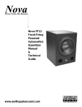
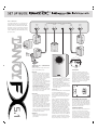
5.1
:
FX 5.1 Subwoofer
This high performance 5.1 system has been
built and tested with care and precision, to
provide first class performance and reliable
operation. To ensure maximum benefit from
ownership, and for reasons of safety, please
read the following information before using
for the first time.
AV RECEIVER/DECODER OUTPUT PANEL
FRONT
LEFT
_
+
REAR
LEFT
_
+
CENTRE
_
+
SUB OUT
REAR
RIGHT
_
+
FRONT
RIGHT
_
+
+
_
WALL
MOUNTING
OPTION
BRACKETS
SUPPLIED
CONNECTING FX 5.1 SUBWOOFER TO
YOUR SYSTEM
The FX5.1 subwoofer may be connected in
any one of the following ways:
POSITIONING
LINE LEVEL
• Using the subwoofer output on your A/V
receiver or decoder connect a single RCA
interconnect to either the left or right line
input on the subwoofer rear panel. This is
the ideal connection type as the subwoofer
output contains the low frequency
information from all channels.
• If no subwoofer or spare line outputs exist
you may connect using a Y-split connector
on the main preamplifier output
connections. Use a Y-split on both right and
left outputs and connect these via an RCA
interconnect to the left and right inputs on
the subwoofer rear panel.
• Alternatively, if your preamplifier has a
spare set of line level outputs, connect left
and right to the FX 5.1 subwoofer L and R
inputs using screened cable.
HIGH LEVEL
5.1
• Use your amplifier's speaker out terminals.
To accommodate the connection of two sets
of cables, red (+) goes to red (+), and
black (-) to black (-), twist wires together
and connect to the amplifier terminals.
• Alternatively use the 'A & B' speaker outputs
on the amplifier if provided - A to your
main speakers and B to the FX5.1
subwoofer. Do this using a length of speaker
cable for each channel, wire your amplifier
outputs to the HIGH LEVEL input terminals,
on the subwoofer amplifier panel. Ensure
there are no stray wire strands that could
possibly short together and damage both
the amplifier and subwoofer.
WARNINGS
• Double-check all connections before
switching on the FX 5.1 system and
your amplifier.
• Ensure that the polarity of the speaker cables
from your amplifier to the subwoofer is
correct - failure to observe this will result in
damage to your amplifier.
• When using the HIGH LEVEL inputs, ensure
that your amplifier is not configured in
bridge mode; damage could result to either
the amplifier or the subwoofer. If in doubt
consult your dealer.
As the FX5.1 subwoofer produces low
frequencies only, it is difficult to detect its
location by ear. It can therefore be placed
anywhere in the room, but optimum
performance will be gained by locating the
subwoofer between the front pair of speakers.
Bass output will increase next to a wall or
especially in a corner; so use the VOLUME
control to compensate if moving your
subwoofer around.
SETTING UP
Ensure the POWER switch is in the OFF position
and that the POWER light is green.
You can operate FX subwoofer in two modes,
AUTO and ON continuously. In AUTO, the
unit remains OFF until an input signal is
detected.
Firstly set VOLUME control to MIN, and the
PHASE switch to 0º. The LED will turn red
when switched ON, or when a signal is
detected in AUTO mode. Play some music
through the system and slowly increase the
volume level control until roughly the correct
amount of bass is present. Listen to the system,
adjusting the VOLUME LEVEL control to
achieve the most seamless integration of
energy with your satellite speakers. In some
installation situations, due to room acoustics,
setting the PHASE switch to 180º will give
better results. Fine adjustment of the controls
will take a little time using a range of different
programme material. Remember that the
object of a subwoofer is to enhance the output
of your main speakers, not overpower it.
AUTO POWER/ SLEEP FUNCTION
The FX 5.1 subwoofer can be left permanently
on in AUTO mode, under which conditions
it will revert to 'sleep' mode after approximately
20 minutes. If not using your subwoofer for
some time, switch OFF and remove the power
cable from the mains outlet.
POWER REQUIREMENTS
Check that the voltage rating displayed on the
rear panel is correct for your area before
connecting. If it is incorrect, move the voltage
selector on the rear panel to the appropriate
voltage. The panel mounted fuse should also
be changed to the correct rating (see below,
under FUSE PROTECTION). If in any doubt,
consult your Dealer or Authorised Service Agent.
5.1
SATELLITES
Crossover frequency
Magnetic shielding:
Weight:
Dimensions H x W x D:
Finish
Supplied accessories
Optional accessories
15 - 100 watts
85dB
6 ohm
140Hz-78kHz
HF: 15mm (5/8 inch) titanium dome,
Neodymium magnet system.
LF: 75mm (3 inch) paper cone
4.5kHz (mid to high)
140Hz (to subwoofer)
Yes
750gms (1.65lbs)
140 x 97 x 95mm
5 1/2 x 3 4/5 x 4 5/16 inch
Silver or black
Wall mounting brackets
25 metres (82 ft 6”) speaker cable
Satellite floor stands available in
matching silver & black
SUBWOOFER
PERFORMANCE
Power output
Frequency response (-6dB)
Driver
Inputs
Power requirements
Fuse ratings
Additional features
Weight
Dimensions H x W x D
Finish
Due to our policy of continuous improvement, this is a specification update
sheet that should be read along with the manual as it provides the latest correct
information. All specifications may be subject to further change without notice.
IMPORTANT
A mains cable is supplied - where the moulded plug is fitted with a mains fuse, always replace with the
same type and rating. If the fitted plug is unsuitable for your type of outlet sockets, it should be cut off
and disposed of safely. The wires in the mains cable are coloured in accordance with the following code:
GREEN AND YELLOW
BLUE
BROWN
EARTH
NEUTRAL
LIVE
As the colours of the wires in the mains cable may not correspond with the coloured markings
identifying the terminals in your plug, proceed as follows:
• The wire that is coloured GREEN and YELLOW must be connected to the terminal in the plug that
is marked either by the letter E, the earth safety symbol, or coloured GREEN or GREEN and YELLOW.
• The wire which is coloured BLUE must be connected to the terminal in the plug which is marked
by the letter N or coloured BLACK.
• The wire which is coloured BROWN must be connected to the terminal in the plug which is marked
by the letter L or coloured RED.
• Ensure that the terminals are tightened securely, and no loose strands of wire are present. Ensure
cord grip is clamped over outer sheath of cable, rather than over the wires.
FUSE PROTECTION
An additional mains fuse is provided in the IEC power inlet on the amplifier panel, removable with
a screwdriver. A fuse of the same type and rating must always replace this.
The correct type is 5mm x 20mm Time Delay (Type T):
• T1.6AL / 125V for AC 220-240V / 50Hz operation,
• T800mAL/ 250V for AC100-120V / 60Hz operation.
Tannoy Limited, Home Audio Division, Coatbridge, Scotland, ML5 4TF.
Tel: +44 (0) 1236 420199 Fax: +44 (0) 1236 428230
e-mail: [email protected] www.tannoy.com
Tannoy adopts a policy of continuous improvement and product specification is subject to change.
100W RMS
45Hz - 140Hz
200mm (8 inch) paper cone
Twin line or speaker level
115 or 230V AC / 50 - 60 Hz,
switching facility on amplifier
panel, 160VA max.
AC100-120V / 60Hz - Fuse: T1.6A L /125V.
AC 220-240V / 50Hz - Fuse: T800mA L /250V
ON / OFF/ AUTO power function
10kg (22lbs)
400 x 230 x 405mm
15.75 x 9.0 x 16.0 inch
Silver or black
FOR YOUR OWN PROTECTION
• Store the complete packaging in case it is needed for re-use.
• Never expose the unit to moisture, water and extremes of temperature or humidity. Specifically, the unit shall
not be exposed to dripping or splashing and that no objects filled with liquids, such as vases, shall be placed
on the unit. Allow 150mm behind the unit to allow for sufficient ventilation. Articles such as newspapers,
tablecloths, curtains etc must not impede the ventilation. Do not operate with the rear panel facing a radiator
or heater. No naked flame sources, such as lighted candles, should be placed on the apparatus.
• Never remove the rear panel of the unit, as there is a risk of electric shock.
• There are no user serviceable parts inside the unit. Always refer servicing to your Tannoy dealer or authorised
service agent.
• Avoid violent shocks to the unit during packing or transportation.
• Do not plug the unit into the mains until all other connections have been made and checked.
• Due to the powerful magnet within FX 5.1 subwoofer, do not place within 1m of a television or
computer monitor.
• When set to the 'standby' and 'off' functions, a small amount of current continues to flow to the apparatus
when not in use. If not used for a long period of time, it is recommended that the apparatus is completely
disconnected at the AC mains socket.
• Terminals marked with the flash symbol are hazardous live and the external wiring connected to these
terminals requires installation by an instructed person or the use of a ready-made lead or cord.
• This apparatus is designed for use in moderate climates.
WARRANTY
Please complete and return the enclosed warranty registration document - this does not limit your legal rights.
This equipment has been produced and tested with care and precision. It is built to give first class service and
carries a 1-year warranty. If the equipment proves to be defective within this period for any reason other than
accident, misuse, unauthorised modification or fair wear and tear, Tannoy will repair any such defect or, at
our option, replace it without charge for parts, labour or return carriage. This warranty is given in addition to
the customer's statutory rights.
If you suspect a problem with your loudspeakers, please contact your local Tannoy dealer who will be
able to advise on appropriate action.
6481 0381
PERFORMANCE
Recommended amplifier power
Maximum Sensitivity (2.83Volts @ 1m)
Nominal impedance:
Frequency response (-6dB)
Drivers: