1
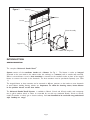
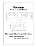
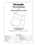
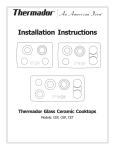
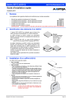
UNIVERSAL COOK’N’VENT ®
INSTALLATION INSTRUCTIONS
MODELS: UCV30 • UCV36 • UCV45
Rating: 120 Volt, 60 Hz., 10.0 Amps.
For Integral Blower Installations:
• Requires Integral Blower: Model # VTN600CVA
• Requires Round Duct Size (6" Diam.)
• Requires Dedicated Branch Circuit Power Supply • 120 Volt AC•
min. 15 Amps., 3 prong receptacle • 60 Hz.
• See Steps 3 and 5 for electrical receptacle and duct outlet location
For Remote Blower Installations:
• Requires Remote Blower: Model # VTR1000Q or VTR600R
• Requires Duct Transition: Model # CVT314 (for 3-1/4" x 14" duct) or
Model # CVT7 (for 7" Diam. Round)
• Requires 4 wires and 1 ground wire connecting blower and vent
• Requires Dedicated Branch Circuit Power Supply • 120 Volt • 15 Amps.,
3 prong receptacle • 60 Hz., AC.
For CVT314:
• Recommend 3-1/4" x 14" to 10" diam. transition for VTR1000Q Remote Blower
• Recommend 3-1/4" x 14" to 8" diam. transition for VTR600R Remote Blower
For CVT7:
• Recommend 7" diam. to 10" diam. transition for VTR1000Q Remote Blower
• Recommend 7" diam. to 8" diam. transition for VTR600R Remote Blower
• See Steps 3 and 5 for electrical receptacle and duct outlet location
INSTALLATION MUST COMPLY WITH ALL APPLICABLE CODES.
PLEASE READ ENTIRE INSTRUCTIONS BEFORE PROCEEDING.
IMPORTANT:
INSTALLER:
OWNER:
SAFETY WARNING:
Save these instructions for the local electrical inspector's use.
Please leave these Installation Instructions with this unit for the owner.
Please retain these instructions for future reference.
Disconnect power by removing plug from receptacle before installing
or servicing this unit.
TABLE OF CONTENTS
Safety Instructions .............................................................................................................................................. pg. 1
Introduction .......................................................................................................................................................... pg. 2
Step 1 Plan the Installation ......................................................................................................................... pg. 3
Step 2 Prepare Countertop Cutout ........................................................................................................... pg. 7
A . Installation with Thermador Cooktop ................................................................................ pg. 8
B. Installation with Another Brand of Cooktop ................................................................... pg. 9
Step 3 Prepare Duct Cutouts in Cabinet ............................................................................................... pg. 10
Step 4 Install Ductwork (Remote Blower- if used) .......................................................................... pg. 11
Step 5 Install Electrical Service ................................................................................................................ pg. 11
Step 6 Mount Vent and Cooktop .............................................................................................................. pg. 11
Step 7 Mount Integral Blower or Remote Blower ............................................................................. pg. 12
Step 8 Verify Installation Operation and Cooktop Alignment ..................................................... pg. 13
SAFETY INSTRUCTIONS
WARNING
WARNING
TO REDUCE THE RISK OF FIRE, ELECTRIC
SHOCK, OR INJURY TO PERSONS,
OBSERVE THE FOLLOWING:
A.
B.
THIS PRODUCT IS INTENDED FOR
GENERAL VENTILATING USE ONLY. DO
NOT USE TO EXHAUST HAZARDOUS OR
EXPLOSIVE MATERIALS OR VAPORS.
Installation work and electrical wiring must be
done by qualified person(s) in accordance with
all applicable codes and standards, including
fire-related construction.
Sufficient air is needed for proper combustion
and exhausting of gases through the flue
(chimney) of fuel burning equipment to prevent
backdrafting. Follow the heating equipment
manufacturer's guideline and safety standards
such as those published by the National Fire
Protection Association (NFPA), and the American Society for Heating, Refrigeration and Air
Conditioning Engineers (ASHRAE), and the local
code authorities.
C
When cutting or drilling into wall or ceiling, do not
damage electrical wiring and other hidden utilities.
D.
Ducted fans must always be vented to the
outdoors.
E.
Always unplug or disconnect the downdraft
from the power supply before servicing.
WARNING
TO REDUCE RISK OF FIRE AND TO PROPERLY EXHAUST AIR, BE SURE TO DUCT
AIR OUTSIDE. DO NOT VENT EXHAUST
AIR INTO SPACES WITHIN WALLS, CEILINGS, ATTICS, CRAWL SPACES OR GARAGES.
WARNING
TO REDUCE THE RISK OF FIRE, USE
ONLY METAL DUCT WORK.
WARNING
TO REDUCE THE RISK OF FIRE, ELECTRIC SHOCK AND INJURY TO PERSONS,
VENTILATOR ASSEMBLIES, MODELS
UCV30, UCV36 AND UCV45 MUST BE
INSTALLED WITH INTEGRAL BLOWER,
MODEL VTN600CVA OR REMOTE BLOWERS MODEL VTR600R OR VTR1000Q.
OTHER VENTILATOR BLOWERS CANNOT
BE SUBSTITUTED.
READ AND SAVE THESE INSTRUCTIONS
Page 1
Figure 1
Top Cap
Filters
Snorkel
Blower Assembly
Support Leg
J-Box
Wing Nuts
INTRODUCTION
GENERALDESCRIPTION
The complete Universal Cook‘n‘Vent®
System consists of the ventilator intake and a blower. See Fig. 1. The blower is either an integral
(mounted on the vent intake in the cabinet under the cooktop) or a remote (roof or outside wall mounted).
When a remote blower is used, a duct transition is mounted on the ventilator intake in place of the integral
blower to connect the intake to the ductwork. The duct transition must be purchased separately. (see Table
1.)
The integral blower or duct transition can be mounted in different positions on the intake to route ductwork
to avoid cabinet, building framing, utilities, etc. Important: To allow for cleaning access, locate blower
in the position closest to the duct outlet.
The Universal Cook‘n’Vent® System is available in 30-inch, 36-inch and 45-inch models, with countertop
trim in either stainless, black, or white. It is intended for use with any residential 30-inch, 36-inch or 45-inch
model (Thermador or other) gas or electric cooktop. It is not intended to be used with any professional
style cooktop or range.
Page 2
STEP 1
PLAN THE INSTALLATION
Carefully follow the planning procedures listed below.
See Figure 2.
A.
Determine whether a remote or integral blower will
be used. Remote blower installation requires 5
wires plus a ground wire to run from the
Cook‘n’Vent® to the blower.
B.
Make sure adequate cabinet and counter space has
been provided for unit service if required.
C.
D.
E.
Provide "make-up air" to installation location to
improve performance and prevent problems, such as
fireplace chimney downdrafts.
F.
Minimize cross drafts created by adjacent open windows, doors, air conditioning, old heating vents,
recessed ceiling lights, and traffic patterns which may
affect performance.
Investigate potential ductwork routes and choose
the shortest possible route from the unit to an
outside wall or roof. For guidance, typical ducting
installations are shown in figures 3 through 6.
G.
For gas cooktop installations make sure that a minimum 10 square inch opening is provided in the toekick or other cabinet area. Inadequate ventilation of
the cabinet below the cooktop may result in flame
outage when operating the vent system.
Determine whether the chosen route of ducting
will meet vent system performance requirements. To do this, measure the duct lengths
needed and determine specific fittings required.
Enter this data in the spaces provided in Table 1.
H.
Follow the duct installation guidelines in Table 2.
PARTS NEEDED:
• Small flat head screwdriver
• Small phillips head screwdriver
PARTS INCLUDED:
• #8, 1" phillips head wood screws (4 ea.)
• wire nut (spring type wire nuts, rated
for a min. of (2 #18 AWG wires, UL
and CSA rated to 600V and 302 deg.F/
150 deg. C)
Parts Needed for Remote Blower:
• 5 min. 18 AWG, max 14 AWG wires and
1 ground wire.
• 1-1/2" box connector
• (3-1/4" x 14") to a 10" Diam. duct
transition for VTR1000R Remote Blower
• (3-1/4" x 14") to a 8" Diam. duct
transition for VTR600R Remote Blower
Parts Needed for Integral Blower:
• 6"-8" Duct Transition for Integral
VTN600CVA Blower
Page 3
Figure 2
INTEGRAL
A
B
10-3/8"
11"
REMOTE
w/ CVT314
8-1/16"
11"
REMOTE
w/ CVT7
12"
10"
Page 4
•
Be certain to avoid interference
with gas and electric supply to
cooktop.
•
Shelving and drawer depths are
dependent upon cooktop depth
and setback.
FIGURES 3 THROUGH 6 ARE EXAMPLES OF POSSIBLE DUCTING
Figure 3
Figure 4
INTEGRAL BLOWER
REMOTE BLOWER
Remote
Blower
Duct Attachment Box
CVT314
VTN600CVA
Wall Cap
WC8
12" Min.
Ground
THROUGH WALL INSTALLATION
ROOF MOUNT INSTALLATION
Figure 5
Figure 6
INTEGRAL BLOWER
REMOTE BLOWER
VTN600CVA
Remote Blower
Duct Attachment
Box CVT314
10" Collar
BLOWER ROTATED 90° FOR
SIDE CONNECTION
THROUGH WALL DUCT INSTALLATION
THROUGH WALL INSTALLATION
Page 5
Page 6
TABLE 2.
•
DUCT WORK INSTALLATION GUIDELINES
Keep duct runs as short and straight as possible.
•
Duct fittings (elbows and transitions) reduce air
flow efficiency.
•
Back to back elbows and "S" turns significantly
reduces air flow and are not recommended.
•
A short straight length of duct at the inlet of the
remote blower gives the best delivery.
•
Transition to round duct as close to the
Cook‘n’Vent® as possible. In order of preference,
use
1st.
10" round duct
2nd. 8" round duct
3rd. 7" round duct
4th. 3-1/4" x 14" duct
5th. 3-1/4" x l0" duct
6th. 6" round duct
•
The use of flexible metal round duct should only
be used when no other duct fitting exists. Limit use
to short lengths and do not crush when making
corners.
•
Where local codes permit, plastic pipe (PVCschedule 40 pipe or ABS pipe 7" or 8" diameter) can
be used in areas of high ground moisture and in slab
floors to eliminate future rusting.
STEP 2
PREPARE COUNTERTOP CUTOUT
For installation of the Cook'n'Vent® with a Thermador
cooktop, refer to Part A and Figure 7. For installation
with another brand of cooktop, refer to Part B and
Figure 8.
For all installations, verify cutouts will clear the inside of
the front countertop support rail. (See cutout depth in
Figure 2). The front and rear cutouts must be straight
and parallel to the front edge of countertop and the
rear backsplash or wall. Assure that the side cutouts
are square to the front and rear cutouts. All illustrations
and dimensions are based upon standard 24" deep by
36" high American style base cabinets with 25"
countertops.
When installing laminated or solid surface countertops
• Use only duct work constructed of materials that
are acceptable by the applicable codes. All duct should
be 26 gauge or heavier to minimize flex due to air flow.
• If the VTR1000Q is used, then a 10" diam. round
duct to match the inlet ring is required or a transition
to a 10" diam. is necessary from other duct sizes.
• If the VTR600R is used, then a 8" diam. round duct
to match the inlet ring is required or a transition to a
8" diam. is necessary from other duct sizes.
• Use sheet metal screws as required to support the
duct weight, and seal all joints with duct tape.
• Be certain that the duct work does not interfere
with floor joists or wall studs.
• Do not exhaust more than one vent into a single
duct run.
• Thermal breaks, such as a short section of
nonmetallic duct, should be used in areas of extreme
cold.
• Always use an appropriate roof or wall-cap with
damper. Laundry type wall caps should never be
used.
such as Surell™ and Corian®, be sure to follow the
countertop manufacturer's instructions regarding minimum corner radii, reinforcement of corners, etc.
For overhead cabinet and cooktop side clearances
consult cooktop Installation Instructions.
A.
INSTALLATION WITH A
THERMADOR COOKTOP
(FIGURE 7 AND TABLE 3)
Provide an opening in the countertop as specified in
Table 3. Make sure the distance from the front of the
countertop to the front of the cutout is not less than
dimension "SB." Verify that the available flat countertop
is greater than dimensions "OW" by "OD." Make
certain the backsplash thickness does not exceed
dimension "BT".
Page 7
TABLE 3 (in inches)
UCV30/36/45 INSTALLATION DIMENSIONS WITH THERMADOR COOKTOPS
Cooktop
Model No.
CW
Cutout
Width
CD
Cutout
Depth
OW
Overall
Width
OD
Overall
Depth
SB
Minimum
Set Back
BT, Max++
Backsplash
Thickness
30” Cooktops: Installed with UCV30
SGS304*
SGSX304*
CET304
CEP304
CEM304
28-15/16
28-15/16
28-3/4
28-3/4
28-3/4
22-1/4
22-1/4
22-1/8
22-1/8
22-1/8
31
31
31
31
31
23-3/4
23-3/4
23-7/8
23-7/8
23-7/8
1-1/2
1-1/2
2-1/2
2-1/2
2-1/2
3/4
3/4
0
0
0
37
37
37
37
37
23-3/4
23-3/4
23-7/8
23-7/8
23-7/8
1-1/2
1-1/2
2-1/2
2-1/2
2-1/2
3/4
3/4
0
0
0
46
46
46
46
46
23-3/4
23-3/4
23-7/8
23-7/8
23-7/8
1-1/2
1-1/2
2-1/2
2-1/2
2-1/2
3/4
3/4
0
0
0
36”Cooktops: Installed with UCV36
SGS365**
SGSX365**
CET365
CEP365
CEM365
34-15/16
34-15/16
34-3/4
34-3/4
34-3/4
22-1/4
22-1/4
22-1/8
22-1/8
22-1/8
45” Cooktops: Installed with UCV45
SGS456
SGSX456
CET456
CEP456
CEM456
43-15/16
43-15/16
43-3/4
43-3/4
43-3/4
22-1/4
22-1/4
22-1/8
22-1/8
22-1/8
Table 3 Notes
*
Dimension "SB" is the minimum distance from the leading
edge of the counter to the leading edge of the cutout.
+ + Dimension "BT" is the thickness of back-splash that
provides
1 / 8 " clearance between vent and backsplash.
Any
backsplash with a curved radius where it meets the
counter will require additional clearance. Thicker
backsplashes may be used by increasing the counter and
cabinet depths.
Figure 7
* *
All dimensions are in inches and are based upon a
standard 24" deep base cabinet with
25"
countertop.
SGC and SGCS cooktops are 1" wider at center of
cooktop than shown in chart above.
Refer to cooktop Installation Instructions for complete
information prior to making any cutouts.
Clearance is provided to allow raising of the hinged main
top.
INSTALLATION WITH THERMADOR COOKTOPS WHEN SPECIFIED
(SEE PART B)
V45
UC V36
C V30
"
- U
1/2
43- -1/2" " - UC
34 8-1/2
2
2-1/4"
1/8
"
CW W
O
BT O CD
D
SB
Page 8
B. INSTALLATION WITH ANOTHER BRAND OF COOKTOP (Figure 8)
The installer will need to have the cooktop installation
instructions available to complete the installation. All
cooktop dimensions should be verified through measurement prior to cutting the countertop:
CCW = Cooktop Cutout Width
CCD = Cooktop Cutout Depth
COW = Cooktop Overall Width
COD = Cooktop Overall Depth
with the above dimensions confirmed, determine the
cutout size as follows:
1.
Find the cutout width, (CW):
If CCW is smaller than the UCV cutout width
then:
Installation
UCV30
UCV36
UCV45
CW
28 - 1 / 2
34 - 1 / 2
43 - 1 / 2
2.
3.
Calculate the cutout depth, CD:
Determine the cooktop overhang (CO)
CO = (COD-CCD)/2 (Assumes front and rear
cooktop overhangs are equal) Calculate the cutout
depth, (CD):
CD = COD - CO+1-7/8"
Determine setback (SB) distance from
front of countertop to front of cutout. SB is
specified in the installation instructions shipped
with the cooktop.
4.
Backsplash thickness must not exceed BT
as calculated below:
BT = 24 7/8" - SB+CO - OD - 2-1/4
(Provides 1 / 8 " clearance between vent and
backsplash.) A negative value for BT means
countertop is too small for the installation.
5.
Verify that the available flat countertop
has a width greater than OW and a depth
greater than OD.
OW depends on the installation:
UCV30: OW equals the greater of COW or 30".
UCV36: OW equals the greater of COW or 36".
UCV45: OW equals the greater of COW or 45".
If CCW is larger than the UCV cutout width then:
CW = CCW
See Figure 8 for UCV cutout widths and dimension
definitions.
OD is determined by: OD=COD+2-1/4".
* Refer to Table 3 Notes on previous page.
6.
Figure 8
Cut countertop using dims: CD, CW and SB as
defined in Figure 8.
INSTALLATION WITH OTHER COOKTOPS WHERE SPECIFIED
(SEE PART B)
45
CV 30
U
V
36
" UC
1/2 2" - UCV
3
4
1/
28- -1/2"
4
3
2-1/4"
1/8
"
BT
CW W
O
C
OD D
SB
Page 9
STEP 3
PREPARE DUCT CUTOUTS IN CABINET
A. Refer to Figure 9. Drop a plumb-line from Point "P" C. Temporarily set intake and cooktop in place and
attach integral blower (or duct transition fitting if a
at the center of the rear countertop cutout.
remote blower is installed). Refer to steps 6 and 7.
Mark this point on the bottom of the cabinet. Draw
Verify that the duct cutouts as marked will match
Line AA through this point and parallel to the front
the hardware installation. Adjust the duct cutout as
of the cabinet. Through the same point draw Line
necessary to match hardware installation.
BB perpendicular to Line AA.
D. Remove temporarily placed hardware and make
B . Use Table 4 to layout the necessary cabinet
cutouts in cabinet.
cutouts for the ductwork. Where a range of
measurements is noted, choose a measurement
E . Make all other cabinet modifications needed to
that allows best clearance from wall studs, floor
provide proper clearances for drawers or removjoists, utilities, or other obstructions.
able shelving.
C
L
Figure 9
B
"P" (Center of Rear Cut-line)
Point
Countertop
Surface
G
Left Side
Right Side
Cabinet Back
F
Plumb line to
intersection A-A &
B-B
30"
Receptacle
Location
D
A
B
A
C
Note: Centerlines of
Rectangular Duct Shown
Adjustable Within Range
H
B
E
Cabinet Bottom Shelf
CABINET CUT-OUT FOR DUCTWORK
TABLE 4
UCV30
UCV36
UCV45
C
7-1/2
7-1/2
7-1/2
INTEGRAL BLOWER VTN600CVA
D
E
F
6
1/4
15-1/2
6
1/4
15-1/2
6
1/4
15-1/2
UCV30
UCV36
UCV45
C
7-1/4
7-1/4
7-1/4
REMOTE BLOWER VTR600R OR VTR1000Q
D
E
F
G
6
12-1/4
12-1/4
6
12-1/4
12-1/4
6
12-1/4
12-1/4
Page 10
G
9
9
9
H
-
H
3
3
3
STEP 4
STEP 6
INSTALL DUCTWORK
(REMOTE BLOWER - if used)
MOUNT VENT & COOKTOP
A.
B.
A.
Install the ductwork and remote blower (if used) in
accordance with the ductwork routing plan developed in Step 1.
Remove grease filters and any packing materials from
inside the intake.
B.
Make sure that the installation complies with all
installation guidelines in Table 2. Check the opening
where ducting passes through the outside wall or
roof has been properly flashed and sealed to prevent
leakage.
Set the vent intake into rear of countertop opening.
Carefully lower it into position so that the flanges on
the rear sides and edges fully support the unit hanging
from the countertop.
C
Loosely fasten lower support legs to vent. Hold the
unit against the rear of the countertop opening, and,
with it in vertical position, slide the brackets down to
meet the bottom of cabinet and fasten to cabinet with
hardware provided. Then tighten brackets on vent.
Refer to Figure 1. Fasten support legs to cabinet
floor.
D.
Place the cooktop in countertop opening with the
rear edge of cooktop overlapping the front edge of
the vent. Make sure rear edge of cooktop does
not bind against front of snorkel. Follow the
manufacturer's installation instructions for installing
the cooktop.
C.
If using integral blower model VTN600CVA proceed to Step 5.
D.
If using remote blower model VTR600R or
VTR1000Q, refer to Installation Instructions with
that model.
STEP 5
INSTALL ELECTRICAL SERVICE
Check your local building codes for proper method of
installation. In the U.S., if there are no applicable local
codes, this unit should be installed in accordance with the
National Electric Code ANSI/NFPA No. 70, Current Issue.
(In Canada, installation must be in accordance with the
CAN 1-B149.1 and .2 - Installation Codes for Gas Burning
Appliances and/ or local codes).
This appliance is factory equipped with a power supply
cord having a three-prong grounding plug (with polarized
parallel blades). IT MUST BE PLUGGED INTO A MATING
GROUNDING TYPE RECEPTACLE, CONNECTED TO
A CORRECTLY POLARIZED 120 VOLT CIRCUIT.
The receptacle should be located under the countertop so
that the 30 inch long power cord from the vent will reach
it. See Figure 9. The cord should be routed beneath the
appliance and away from heat generated by the cooktop.
Access should not be obstructed by blower, cabinet work,
ductwork or electrical/gas utilities for the cooktop. All
power for the vent system (including the remote blower,
if used) is supplied via the cord to the intake unit. The
outlet must have its own dedicated branch circuit from
the main service panel.
Do not plug vent cord into receptacle until Step 8.
Page 11
STEP 7
Figure 10
MOUNT INTEGRAL BLOWER OR
Remote Blower Transition
MOUNT INTEGRAL BLOWER OR Remote
Blower Transition
Integral Blower VTN600CVA Only
A. Place blower in front of intake inside of cabinet,
take conduit and blower wires and guide them
towards the right at the floor of the cabinet.
B. On each side of blower housing there is a
flanged edge. When placing the housing onto the
intake, these flanges need to be positioned in line
with intake flanges.
C. Place the support bars over the screws on the
left and right sides of the housing. Secure blower
with wing nuts.
D. Snap 900 conduit connector onto end of conduit
and wires. Secure connector to hold at bottom of JBox, ensuring that wires are pulled through and any
slack is taken up.
E. To hook up electrical wiring, press down on
terminal block tab with small flathead screwdriver
and hook up wires into the terminal blocks (as per
wiring diagram and color key). Make sure to
connect blower wire and the J-Box ground wire with
the wire nut provided. Replace J-Box cover.
F. Connect ductwork to blower.
Remote Blower VTR600R or VTR1000Q Only
A. Secure 1/2" box connector to hold at bottom of
J-Box. Pull 5 wires through connector ensuring that
any slack is taken up.
B. To hook up electrical wiring, press down on
terminal block tab with small flathead screwdriver
and hook up wires into the terminal blocks (as per
wiring diagram and color key). Make sure to connect blower wire and the J-Box ground wire with the
wire nut provided. Replace J-Box cover.
C. Connect ductwork to blower.
UCV WIRING DIAGRAM
COLOR KEY
Red
= Low
Blue = Medium
Black = High
White = Neutral
Green = Ground
Figure 11
Note: Use spring type wire nuts supplied to connect wires per Fig. 11 wiring diagram. (Lost or
missing wire nuts should only be replaced with:
Spring type wire nuts, rated for a minimum of (2)
#18ga wires and max. of (4) #14ga wires, UL &
CSA rated to 600V and 302 deg.F/150 deg. C).
Wire to remote blower
min. 18 AWG wire
max. 14 AWG wire
Page 12
STEP 8
Figure 12
VERIFY INSTALLATION,
OPERATION & COOKTOP
ALIGNMENT
Snorkel Up/
Down button
Before performing this procedure, verify that all
packing materials were removed from inside the
lower enclosure front and that the grease filters
have been properly installed. Refer to the Care and
Use Manual for instructions regarding filter installation.
Blower Controls
Plug the vent power cord into a proper electrical receptacle and ensure that the circuit is energized.
A. Raise the snorkel to its fully extended position by
pressing the Snorkel Up/Down button once (Figure
12). Do not hold the button. The elevating motor
will stop when the snorkel reaches its full height.
(Note: the blower will not operate unless the snorkel
is fully raised).
B . Remove filters from packaging and install (refer to
Care and Cleaning section for details).
C. Turn the blower ON by pushing the Low Blower
Speed button on the snorkel (Figure 12). Let the
blower run several minutes at each speed to
evaluate its operation.
D. With the blower running, lower the snorkel to its fully
retracted position by pushing the Snorkel Up/Down
button once. The blower will immediately turn off.
Figure 13
E . Raise and lower the vent again. Check to make
sure that the top cap on the snorkel does not
catch on the back edge of the cooktop when it is
lowered. If interference occurs, adjust the position of the cooktop by moving it against the front
edge of the countertop cutout. Re-secure the
cooktop to the countertop. Failure to eliminate
interference may result in permanent damage to
the vent. Also, ensure that the vent support legs
have been properly secured to the cabinet base
using the screws provided.
F . The height of the snorkel top can be adjusted so
that the snorkel top cap is visible when installed
with cooktops that have a higher cooking surface.
Make this adjustment after installation is complete. First unplug the power cord, remove the
J-Box cover, loosen the adjustment screw and
push up on the adjustment bracket, (see Figure
13).
NOTE: To prevent damage to any internal
parts, the snorkel should be in the raised
position when this adjustment is made.
If the vent system does not operate satisfactorily during any of the above procedures,
review all steps in these Installation Instructions to ensure that nothing has been omitted
or overlooked. Also, refer to the Care & Use
Manual for additional information or call
Thermador Customer Support 1-800-7354328.
Page 13
NOTES
5551 McFadden Avenue, Huntington Beach CA, 92649 • 800-735-4328
BSH Home Appliances Corp. • Litho in U.S.A. 10/02
5060004249 (8209)