1
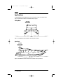
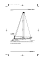
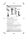
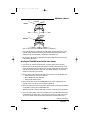
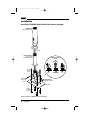
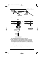
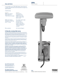
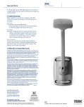
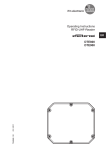
XM5 OM
4/8/03
09:56 AM
Page 1
OWNER’S MANUAL
READ
THIS
FIRST!
XM5
MARINE SATELLITE RADIO ANTENNA
XM5 OM
4/8/03
09:56 AM
Page 2
Table of Contents
About Installation . . . . . . . . . . . . . . . . . . . . . . . . . . . . . . . . . . . . . . . . . . . . . . . . . . . . . . . . . . . . 2
Introduction . . . . . . . . . . . . . . . . . . . . . . . . . . . . . . . . . . . . . . . . . . . . . . . . . . . . . . . . . . . . . . . . 3
Applications . . . . . . . . . . . . . . . . . . . . . . . . . . . . . . . . . . . . . . . . . . . . . . . . . . . . . . . . . . . . . . . . 4
Installation . . . . . . . . . . . . . . . . . . . . . . . . . . . . . . . . . . . . . . . . . . . . . . . . . . . . . . . . . . . . . . . . . 6
Parts for TERK XM5 Marine Satellite Radio Antenna . . . . . . . . . . . . . . . . . . . . . . . . . . . . . . . . 6
Recommended Tools and Supplies . . . . . . . . . . . . . . . . . . . . . . . . . . . . . . . . . . . . . . . . . . . . 6
Installation Precautions and Tips . . . . . . . . . . . . . . . . . . . . . . . . . . . . . . . . . . . . . . . . . . . . . . 6
Installing the TERK XM5 Marine Satellite Radio Antenna. . . . . . . . . . . . . . . . . . . . . . . . . . . . . 7
Use and Care . . . . . . . . . . . . . . . . . . . . . . . . . . . . . . . . . . . . . . . . . . . . . . . . . . . . . . . . . . . . . . 10
Troubleshooting . . . . . . . . . . . . . . . . . . . . . . . . . . . . . . . . . . . . . . . . . . . . . . . . . . . . . . . . . . . . 10
Specifications . . . . . . . . . . . . . . . . . . . . . . . . . . . . . . . . . . . . . . . . . . . . . . . . . . . . . . . . . . . . . . 10
Electrical Specifications . . . . . . . . . . . . . . . . . . . . . . . . . . . . . . . . . . . . . . . . . . . . . . . . . . . 10
Mechanical Specifications. . . . . . . . . . . . . . . . . . . . . . . . . . . . . . . . . . . . . . . . . . . . . . . . . . 11
Other Specifications . . . . . . . . . . . . . . . . . . . . . . . . . . . . . . . . . . . . . . . . . . . . . . . . . . . . . . 11
Limited Warranty . . . . . . . . . . . . . . . . . . . . . . . . . . . . . . . . . . . . . . . . . . . . . . . . . . . . . . . . . . . 11
About XM Satellite Radio . . . . . . . . . . . . . . . . . . . . . . . . . . . . . . . . . . . . . . . . . . . . . . . . . . . . . 11
About Installation
Installation of marine audio components can require extensive experience with a variety of mechanical
and electrical procedures. Although the instructions in this guide explain how to install the TERK XM5
Marine Satellite Radio Antenna in a general sense, they do not show the exact installation methods for
your particular boat.
IMPORTANT: If you are not comfortable performing a complex installation, ask your local
marine audio dealer about professional installation options.
2
Table Of Contents
XM5 OM
4/8/03
09:56 AM
Page 3
XM5 Owner’s Manual
Introduction
The TERK XM5 Marine Satellite Radio Antenna is a high-performance antenna designed specifically
for XM Satellite Radio reception on recreational marine craft such as fishing boats, sport boats,
yachts, and sailboats. Its features include:
• Rugged antenna to withstand high-vibration salt-water environment
• High-mount capability on the boat for maximum, line-of-sight, signal path from XM satellites
• Pre-assembled, flange-mount clamp with quick-release adjustable, ratchet lever uses industrystandard 1"-14 threads for easy antenna installation
• 30' of attached, low-loss, coaxial cable and FAKRA connector for extended cable routes and ease
of installation
• Cable management system to protect cables
• Meets or exceeds all XM Satellite Radio mobile-antenna specifications
• Shock- and vibration-proof design
The TERK XM5 Marine Satellite Radio Antenna is easy to install on most recreational marine craft.
The package includes all the necessary mounting hardware, as well as color-coded cable connectors
to ensure complete compatibility with all XM receivers. Remember to save your sales receipt and this
guide so both are available for future reference.
NOTE: To achieve best XM Satellite Radio reception, also refer to your XM radio’s owner’s manual.
Introduction
3
XM5 OM
4/8/03
09:56 AM
Page 4
Applications
The TERK XM5 Marine Satellite Radio Antenna can be installed on a variety of recreational marine
craft, as shown below. For details, see Installation starting on page 6.
Fishing Boats
TERK XM5
Marine Satellite
Radio Antenna
Figure 1. The TERK XM5 is shown installed on the fishing boat’s fly bridge.
Sport Boats
TERK XM5
Marine Satellite
Radio Antenna
Figure 2. The TERK XM5 is shown mounted on the electronics arch of a sports boat.
4
Applications
XM5 OM
4/8/03
09:56 AM
Page 5
XM5 Owner’s Manual
Sailboats
TERK XM5
Marine Satellite
Radio Antenna
Figure 3. The TERK XM5 is shown installed on an antenna extension on the stern of a sailboat.
NOTE: When mounted in this configuration, the mast and sails may interfere with reception when
the craft is at certain angles to the satellite.
Applications
5
XM5 OM
4/8/03
09:56 AM
Page 6
Installation
Parts for TERK XM5 Marine Satellite Radio Antenna
(1) TERK XM5 Antenna
With 30'of Attached Coaxial Cable
(4) Hex Bolts/Washers/Nuts
8.75"
(4) Cable Tie Wraps
(1) Mounting Bracket
With Mounting Hardware
SAT
TER
(1) FAKRA
Case/Clip
(1) Splitter
Figure 4. Verify that your TERK XM5 package includes the above items.
Recommended Tools and Supplies
• Any electric drill and bits (to drill mounting holes for the mounting bracket)
• Any socket tool/wrench set (to tighten machine bolts and hex nuts)
• Any tool to help cable routing (e.g., flat dental pick, screwdriver, etc.)
• Grommets and silicone sealer (for cable routes)
• (Optional) Antenna Extension with 1"-14 threads
• (Optional) Substitute any mounting bracket with 1"-14 threads for the supplied bracket
Installation Precautions and Tips
• When selecting an antenna location, make sure the antenna is not enclosed by any metal material.
If a metal fly bridge is to be used, the antenna must protrude at least 5 inches above the bridge’s
top edge. Consider using an antenna extension to increase the height above the boat.
• Also, at the proposed site, verify that there is at least a 20-degree clearance from any metallic
obstruction on all sides, as shown in figure 5 (on the next page).
• Prior to installation, turn off all audio systems and other electrical devices. Disconnect the (–)
negative lead from the boat’s battery.
• At the installation site, locate and make a note of all fuel lines, cables, and electrical wiring.
Use extreme caution when cutting or drilling in and around these areas. Always wear protective
eyewear when using tools.
6
Installation
XM5 OM
4/8/03
09:56 AM
Page 7
XM5 Owner’s Manual
Clear Signals
20° Clearance
Correct
XM5
Blocked Signals
Incorrect
XM5
Figure 5. Correct and incorrect TERK XM5 locations on a fishing boat.
• As you plan the cable route, avoid running the cable through any component that may cause
excessive chafing. Doing so may erode the jacket and break signal continuity. Also, avoid
kinking, pinching, excessive bending, or twisting of the cable during a run.
• Do not trim the cable length. It is optimized for best signal reception. Coil and store any excess
cable behind the XM receiver.
Installing the TERK XM5 Marine Satellite Radio Antenna
1. At the chosen site, install the mounting bracket, as shown in figure 6 (on the next page).
2. Route the antenna cable through the (optional) antenna extension and out through the access
hole on the mounting bracket (see figure 6 on the next page). Firmly tighten the antenna to the
extension and then the extension to the bracket. If an antenna extension is not used, firmly
tighten the antenna directly to the bracket.
3. Route the antenna cable to the back of the XM receiver using any or all of the following ways:
• Through existing access holes in the boat’s hull
• Along or behind interior walls below deck
• Through a cabin window opening
4. On the antenna cable’s end, insert the FAKRA SMB connector into the supplied plastic case,
as shown in figure 7 on page 9. Then lock it with the supplied clip.
5. When using an XM receiver that has dual-antenna inputs, install the splitter (mounting hardware
not supplied) near the back of the installed XM receiver.
NOTE: For convenience, fasten the splitter with a tie wrap to a nearby access hole (If available).
6. Connect the antenna cable to the input on the splitter. Then connect TER and SAT cables from it
to the XM receiver, as shown in figure 8 on page 9. If your receiver has a single antenna input,
do not use the splitter. Instead, plug the antenna cable directly to the XM receiver’s input.
Continued on next page...
Installation
7
XM5 OM
4/8/03
09:56 AM
Page 8
Installation
Installing the TERK XM5 Marine Satellite Radio Antenna (continued)
XM5 Antenna
(with 30' of attached cable)
Antenna Cable
Antenna Extension
(optional – length
determined by application)
Adjusting the Tilt
(side view)
For parts,
see figure 4
on page 6.
❶
unlock
To Splitter, see
figures 7 and 8
on page 9.
Mounting Bracket
(with adjustable, ratchet tilt)
diam. = 0.25"
Mounting Surface
For parts,
see figure 4
on page 6.
Figure 6. Installing the TERK XM5 antenna and bracket.
8
Installation
❷
adjust tilt
(10° increments)
❸
lock
XM5 OM
4/8/03
09:56 AM
Page 9
XM5 Owner’s Manual
Curry Case
(Satellite)
❷
❸
❶ FAKRA Connector
Assembled
XM5 Antenna
Cable with Case
Clip
Cable from
XM5 Antenna
Figure 7. Inserting the FAKRA SMB connector into the plastic case.
Antenna
1 2
Antenna
SIR5 Receiver
OR
Dual-Antenna Inputs
SIR5 Receiver
Single-Antenna Input
(rear view)
(rear view)
White Case
(Terrestrial)
TER
Curry Case
(Satellite)
Curry Case
(Satellite)
SAT
Splitter
From TERK SIR5
Marine Satellite
Radio Antenna
(Supplied)
Curry Case
(Satellite)
From TERK SIR5 Marine
Satellite Radio Antenna
Figure 8. Wiring diagram shows antenna connections to an XM receiver.
7. If needed, adjust the tilt so the antenna is perpendicular to the horizon (see figure 6 on the
previous page). Turn on the XM system and tune the radio to channel one (i.e., the preview
channel) to verify that the antenna is properly installed. If there are any problems, review the
installation steps and verify that each one was performed correctly. Also see Troubleshooting on
the next page.
8. After the system has been tested successfully, continue dressing the cable from the antenna to
the receiver for best appearance and complete any remaining installation. Use the supplied
cable tie wraps to secure cables from flagging in the wind and catching on objects.
NOTE: For additional help with cable routing, consult your local marine audio dealer.
Installation
9
XM5 OM
4/8/03
09:56 AM
Page 10
Use and Care
In normal daily use, the TERK XM5 Marine Satellite Radio Antenna is a rugged, high-performance
antenna that does not require any special attention.
Troubleshooting
Symptom
Solutions
XM radio displays “Antenna”
or “Check Antenna” message
• Check antenna connections to the XM receiver.
XM radio displays “No Signal”
message
• Boat may be in an area where the XM signal is
obstructed. Move the boat to more open surroundings.
Other symptoms
• Call TERK for help at 1-800-942-TERK (8375) on
any business day, between 9 A.M. and 5:30 P.M., EST
and ask for Technical Support.
Specifications
Electrical Specifications
Passive Satellite Antenna Element –
Frequency:
2332.5 to 2345.0 MHz
Gain:
2 dBic
Bandwidth:
12.5 MHz
Impedance:
50 ohms
Elevation Plane Field of View:
25° to 60°, elevation
Azimuth Plane Field of View:
Omnidirectional
Polarization:
LHCP (Circular)
LNA for Satellite Signals –
Gain:
30 dB, typical
Noise Figure:
1.2 dB, maximum
Dc Bias:
4.5 Vdc, nominal
Current Drain:
Filter Attenuation:
55 mA, maximum
25 dB, minimum
Cable –
Type:
Coaxial
Length:
30 feet
Connector:
FAKRA/SMB (Key Code: K, Color: Curry)
10 Use and Care/Troubleshooting/Specifications
XM5 OM
4/8/03
09:56 AM
Page 11
XM5 Owner’s Manual
Mechanical Specifications
Antenna –
Radome Height:
6.25 inches
Radome Diameter:
1.50 to 1.75 inches
Radome Material:
White Polycarbonate
Antenna Base –
Height:
2.50 inches
Diameter:
Up to 1.875 inches
Material:
White Polycarbonate
Flange Mount Hardware –
Screws, Nuts, and Washers:
Stainless Steel
Weight (All Parts):
2.1 lbs
Other Specifications
Temperature:
-40 °C to +105 °C, operating
-45 °C to +120 °C, storage
TERK Technologies strives to maintain and exceed the highest consumer standards. Due to these ongoing efforts, modifications
may be made from time to time to existing products without any prior notice. Specifications and appearance may differ from
those listed or shown in this manual. The XM name and related logos are trademarks of XM Satellite Radio, Inc. TERK and TERK
Technologies are trademarks of TERK Technologies Corp., Commack, NY.
Limited Warranty
TERK Technologies Corp. (TERK) warrants this product against defects in materials or workmanship
for 1 year from the date of purchase. During this warranty period, this product will be replaced
without charge. This warranty does not cover any damage due to act of God, commercial use,
accident, misuse, abuse or negligence.
This warranty is only valid in the USA. Replacement as provided under this warranty is the exclusive
remedy of the consumer. TERK shall not be liable for any incidental or consequential damages for
breach of any expressed or implied warranty on this product, except to the extent prohibited by
applicable law. Any implied warranty or merchantability or fitness for a particular purchase on this
product is limited to the duration of this warranty.
About XM Satellite Radio
For more information about XM Satellite Radio service, visit their web site at: www.xmradio.com
Specifications/Limited Warranty/About XM Satellite Radio 11
XM5 OM
4/8/03
09:56 AM
Page 12
TERK
For Technical Support:
1.800.942.TERK (8375)
For information about our full
product line, visit our web site at:
www.terk.com
TERK is a registered trademark.
The TERK logo is a trademark of
TERK Technologies Corp.
©2002 Terk Technologies Corp.
64P002