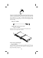
1
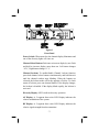
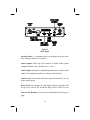
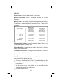
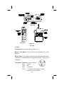
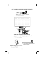
Telex
Operating Instructions
USR-100
Table of Contents
General . . . . . . . . . . . . . . . . . . . . . . . . . . . . . . . . . . . . . . . . . . . .
USR-100 Features . . . . . . . . . . . . . . . . . . . . . . . . . . . . . . . . . . . .
Frequency Agility . . . . . . . . . . . . . . . . . . . . . . . . . . . . . . . . . .
Channel Lockout . . . . . . . . . . . . . . . . . . . . . . . . . . . . . . . . . . .
Dual Squelch . . . . . . . . . . . . . . . . . . . . . . . . . . . . . . . . . . . . . .
Posi Phase Diversity . . . . . . . . . . . . . . . . . . . . . . . . . . . . . . . .
Antennas . . . . . . . . . . . . . . . . . . . . . . . . . . . . . . . . . . . . . . . . .
Computer Controlled Channels. . . . . . . . . . . . . . . . . . . . . . . .
Displays. . . . . . . . . . . . . . . . . . . . . . . . . . . . . . . . . . . . . . . . . .
Audio Output . . . . . . . . . . . . . . . . . . . . . . . . . . . . . . . . . . . . .
Power . . . . . . . . . . . . . . . . . . . . . . . . . . . . . . . . . . . . . . . . . . .
Audio. . . . . . . . . . . . . . . . . . . . . . . . . . . . . . . . . . . . . . . . . . . .
USR-100 . . . . . . . . . . . . . . . . . . . . . . . . . . . . . . . . . . . . . . . . .
SH-100 . . . . . . . . . . . . . . . . . . . . . . . . . . . . . . . . . . . . . . . . . .
LT-100. . . . . . . . . . . . . . . . . . . . . . . . . . . . . . . . . . . . . . . . . . .
Power Switch . . . . . . . . . . . . . . . . . . . . . . . . . . . . . . . . . . . . .
Channel Select Buttons . . . . . . . . . . . . . . . . . . . . . . . . . . . . . .
Channel Lockout . . . . . . . . . . . . . . . . . . . . . . . . . . . . . . . . . . .
Diversity Display . . . . . . . . . . . . . . . . . . . . . . . . . . . . . . . . . .
AF Display . . . . . . . . . . . . . . . . . . . . . . . . . . . . . . . . . . . . . . .
RF Display . . . . . . . . . . . . . . . . . . . . . . . . . . . . . . . . . . . . . . .
Antenna Jacks . . . . . . . . . . . . . . . . . . . . . . . . . . . . . . . . . . . . .
Audio Output . . . . . . . . . . . . . . . . . . . . . . . . . . . . . . . . . . . . .
Audio Adjust . . . . . . . . . . . . . . . . . . . . . . . . . . . . . . . . . . . . . .
Audio Level . . . . . . . . . . . . . . . . . . . . . . . . . . . . . . . . . . . . . .
Power Jack . . . . . . . . . . . . . . . . . . . . . . . . . . . . . . . . . . . . . . .
Power Cord Retainer . . . . . . . . . . . . . . . . . . . . . . . . . . . . . . . .
Receiver Set-up . . . . . . . . . . . . . . . . . . . . . . . . . . . . . . . . . . . .
-i-
1
1
1
1
1
2
2
2
3
3
3
3
4
5
6
7
7
7
7
7
7
8
8
8
8
8
8
9
Table of Contents (continued)
SH-100 Features . . . . . . . . . . . . . . . . . . . . . . . . . . . . . . . . . . . .
Power Switch . . . . . . . . . . . . . . . . . . . . . . . . . . . . . . . . . . . .
Battery Test Button . . . . . . . . . . . . . . . . . . . . . . . . . . . . . . . .
Battery Meter . . . . . . . . . . . . . . . . . . . . . . . . . . . . . . . . . . . .
Channel Select Switches . . . . . . . . . . . . . . . . . . . . . . . . . . . .
Microphone Gain . . . . . . . . . . . . . . . . . . . . . . . . . . . . . . . . .
Transmit Power Switch . . . . . . . . . . . . . . . . . . . . . . . . . . . . .
Set-Up . . . . . . . . . . . . . . . . . . . . . . . . . . . . . . . . . . . . . . . . . .
LT-100
Power Switch . . . . . . . . . . . . . . . . . . . . . . . . . . . . . . . . . . . .
Battery Test Button . . . . . . . . . . . . . . . . . . . . . . . . . . . . . . . .
Battery Meter . . . . . . . . . . . . . . . . . . . . . . . . . . . . . . . . . . . .
Microphone Connector . . . . . . . . . . . . . . . . . . . . . . . . . . . . .
Channel Select Switches . . . . . . . . . . . . . . . . . . . . . . . . . . . .
Microphone Gain . . . . . . . . . . . . . . . . . . . . . . . . . . . . . . . . .
Transmit Power Switch . . . . . . . . . . . . . . . . . . . . . . . . . . . . .
Set-Up . . . . . . . . . . . . . . . . . . . . . . . . . . . . . . . . . . . . . . . . . .
System Set-Up. . . . . . . . . . . . . . . . . . . . . . . . . . . . . . . . . . . .
Antenna Placement . . . . . . . . . . . . . . . . . . . . . . . . . . . . . . . .
Antenna Placement for Optimum Range
and Rack Mounting . . . . . . . . . . . . . . . . . . . . . . . . . . . . . . .
Bracket Mounting . . . . . . . . . . . . . . . . . . . . . . . . . . . . . . . . .
Antenna Connection . . . . . . . . . . . . . . . . . . . . . . . . . . . . . . .
Installing Rack Mounts . . . . . . . . . . . . . . . . . . . . . . . . . . . . .
Assembly. . . . . . . . . . . . . . . . . . . . . . . . . . . . . . . . . . . . . . . .
Double Mounting . . . . . . . . . . . . . . . . . . . . . . . . . . . . . . . . .
Accessories and Replacement . . . . . . . . . . . . . . . . . . . . . . . . . .
Front Connector Mounting Kit . . . . . . . . . . . . . . . . . . . . . . .
FCC Information. . . . . . . . . . . . . . . . . . . . . . . . . . . . . . . . . . . .
Customer Service Information . . . . . . . . . . . . . . . . . . . . . . . . .
-ii-
11
11
11
11
11
11
11
11
12
12
12
12
13
13
13
13
14
14
14
15
16
17
17
18
19
20
21
22
GENERAL INFORMATION
The Telex Model USR-100 Receiver and associated Transmitters is a
100 Channel, frequency-selectable full diversity system operating within
the frequency range of 668.0 to 746.0 MHz on specific pre-set frequencies. Systems consisting of the USR-100 and its companion transmitter
are capable of operating on at least 5 frequencies in a TV channel
simultaneously, sometimes more depending on the individual venue.
Certain frequencies can be combined to form a set of systems compatible
for simultaneous use. Digital frequency control of the USR-100 permits
flexibility within a given area and assures confidence in the equipment
capability.
FEATURES
The USR-100 features a pair of unique UP-UP channel slewing push
buttons that makes channel changing easy. Simply press each button
until the desired digit appears. A 2 digit 7 Segment LED indicates
the Channel. If there is any interference from other wireless users or
a TV station in the area, it is a simple matter to change the USR-100
frequency. The frequency agility of the USR-100 is also very useful
for itinerant users and rental customers.
Prevents channel changes by unauthorized personnel or accident. The
lockout status is unaffected when the unit is turned off or unplugged.
The channel display will flash 4 times when the USR is turned on if
the lockout is enabled. The display will flash rapidly if someone tries
to change the channel when the lockout is enabled.
The USR-100 features not only a Tone Coded Squelch on a little used
tone frequency of 31.250 KHz but also uses RSSI Amplitude
Squelch. In the case where there is an RF carrier or noise interference
on the channel, the squelch will not open because there is no accom
panying tone. The USR-100 must receive the correct tone from the
transmitter and the RF carrier before the squelch will open.
-1-
Posi Phase Diversity
The USR-100 receiver utilizes Telex’s patented Posi Phase auto
diversity circuit. Unlike other types of diversity which receive with
only one antenna at a time, Posi Phase utilizes both antennas at all
times. This results in a stronger signal from the microphone for
cleaner audio and greater range.
If the microphone signal begins to go out of phase (a common cause
of “drop outs” with other types of diversity) the Posi Phase circuit
adjusts the phase angle between the two antennas’ receiving circuits
to prevent phase cancellation. This action is indicated by the 0 and
180 degree diversity lights on the front panel
Antennas
There are two TNC type antenna connectors on the rear panel. These
connectors are superior to the more common BNC connectors, both
electrically and mechanically. TNC connectors are becoming the
standard of the industry due to their heavy use in the Cellular Phone
industry. Quarter wave antennas are supplied for normal use or an
optional antenna accessory kit can be used to rack mount the antennas. Optional half wave antennas with coax can be used for remote
installations. Both antennas must be used as both are active at all
times, unlike other types of diversity that only use one antenna at a
time.
Computer Controlled Channels
The VCO (Voltage Controlled Oscillator), which is the heart of any
Phase Locked Loop Receiver, is controlled by an on-board PIC
microprocessor. Each individual USR-100 RF stage tuning element
is also under the direct control of the microprocessor. This directs the
receiver to undergo an “Automatic Self Tune” step each time the
channel is changed. This is unlike many receivers on the market that
simply have “wide band” designs that allow interference to enter the
most sensitive stages of a receiver to cause inter-modulation and
noise. Other items under processor control are the channel selection,
spacing and display, the AF and RF displays and diversity operations.
This marriage of digital precision with real analog sound provides
the user with the best of both technologies.
-2-
Displays
The 7 Segment LED channel display already mentioned (00 to 99).
2. A 5 segment LED light array for AF, that aids in setting microphone gains and monitoring receiver microphone and line level
outputs. Light numbers 4 and 5 have a Peak Hold feature.
3. A 5 segment LED light array for RF, that aids in checking the
transmitter and monitoring for the possibility of initial interference.
4. A 2 segment LED array that indicates diversity action and antenna
configuration.
Audio Output
An XLR type connector is located on the rear panel that provides
either line level audio or microphone level audio output, which is
controlled by a slide type switch also located on the rear pane. The
output level is adjustable with a screwdriver accessible potentiometer
located on the rear panel.
Power
The USR-100 will operate from the supplied AC adapter or any
nominal 12-15 volt AC/DC 600 mA supply.
Audio
The USR-100 audio circuitry is designed to complement the transmitter audio. A compandor circuit is utilized to enhance the dynamic
range. A slow turn-on circuit prevents the audio output stage from
passing noise spikes present during receiver power up conditions.
-3-
USR-100 Receiver
Specifications
RF Frequency Range. . . . . . . . . . . . . . . 668.0 to 746.0 MHz
Channels . . . . . . 100 (0-99) (within TV Ch. 47/48 & 58/59)
R.F. Stability . . . . . . . . . . . . . . . . . . . . . . . . 0.005% or better
Modulation Type . . . . . . . . . . . . . . . . . FM, 40 KHz nominal
Type. . . . . . . . . . . . . . . . . . Single Conversion, 10.7 MHz I.F.
I.F. Bandwidth. . . . . . . . . . . . . . . . . 230 KHz at -3 db points.
Image Rejection . . . . . . . . . . . . . . . . . . . . . . . 65dB or better
Squelch . . . . . . . . . . . . 31.250 KHz Tone + RSSI Amplitude
Audio Output . . . . . . . . . . . . Level, 0.775V RMS/100k load
-20 dBV, 600 Ohm load
Receiver Sensitivity . . . Less than 0.8 uV for 12 dB SINAD
FCC . . . . . . . . . . . . . . . . . . . . . . . . . . . . Notification, Part 15
Diversity . . . . . . . . . . . . . . Continuous Posi Phase Diversity
Both antennas are fully employed at all times
to maximize signals.
RF Selectivity . . . . . . . . . . . . . Tracked Ceramic Resonators.
Not Broadband.
-4-
Model SH-100 Transmitter
Specifications
Frequency of operation . . . . . . . . . 668.000 to 746.000 MHz.
(Current models operate in 2 frequency ranges.)
668.000 to 679.500 MHz and 734.100 to 745.500 MHz.
Number of Channels . . . . . . . . 100 User Selectable Channels
in each range.
Power Output (Terminated). . . 10 mW, High switch setting,
1.0 mW Low.
Antenna . . . . . . . . . . . . . . . . . . . . . . . . Permanently attached.
Modulation . . . . . . . . . . . . . . . . FM, +/- 40 KHz Deviation,
50 us pre-emphasis.
Frequency Response (System) . . . . . . . . 50 Hz to 15000 Hz
Microphone . . . . . . . . . . Dynamic or Electret, + 5 VDC Bias.
Tone Squelch. . . . . . . . . . . . . . . . . . . . . Full time, 31250 Hz
DC Power . . . . . . . . . . . . . . . . 2 AA Size Alkaline Batteries.
Battery Life . . . . . . . . . 9 Hours, High Power, 12 Hours Low
Low Battery Indicator . . . . Built-in Fuel Gauge, Test Switch
Approvals . . . . . . . . . . . . . . . . . . . . . . . . . . . . FCC, Part 74H
Industry Canada, RSS123
-5-
Model LT-100 Transmitter
Specifications
Frequency of operation . . . . . . . . . 668.000 to 746.000 MHz.
(Current models operate in 2 frequency ranges.)
668.000 to 679.500 MHz and 734.100 to 745.500 MHz.
Number of Channels . . . . . . . . . . . . . . . . 100 User Selectable
Channels in each range.
Power Output (Terminated). . . . 10 mW, High switch setting,
1.0 mW Low
Antenna . . . . . . . . . . . . . . . . . . . . . . . . Permanently attached
Modulation . . . . . . . . . . . . . . . . . FM, +/- 40 KHz Deviation,
50 us pre-emphasis.
Frequency Response (System) . . . . . . . . 50 Hz to 15000 Hz
Microphone . . . . . . . . . . Dynamic or Electret, + 5 VDC Bias
Tone Squelch. . . . . . . . . . . . . . . . . . . . . Full time, 31250 Hz
DC Power . . . . . . . . . . . . . . . . 2 AA Size Alkaline Batteries
Battery Life . . . . . . . . . 9 Hours, High Power, 12 Hours Low
Low Battery Indicator . . . . Built-in Fuel Gauge, Test Switch
Approvals . . . . . . . . . . . . . . . . . . . . . . . . . . . . FCC, Part 74H
Industry Canada, RSS123
-6-
Figure 1
Front Panel
Power Switch: When turned on, the channel display illuminates and
one of the diversity lights will come on.
Channel Select Buttons: Push once to increase display by one. Push
and hold to increase display more than one. Left button changes
“10’s”, Right button changes “1’s”.
Channel Lockout: To enable/disable Channel Lockout function,
press both channel select buttons simultaneously and hold them in
until the channel readout stops blinking. When the buttons are
released, the lockout mode will be the opposite of before. To check
status of lockout, press one channel button. If the display changes,
the lockout is disabled. If the display blinks rapidly, the lockout is
activated.
Diversity Display: LED’s indicate diversity operation.
AF Display: A 5-segment three-color LED Display indicates the
relative modulation of the system.
RF Display: A 5-segment three color LED Display indicates the
relative signal strength from the transmitter.
-7-
Figure 2
Rear Panel
Antenna Jacks: Two antenna jacks for posi phase diversity reception. Attach an antenna to each jack.
Audio Output: XLR type jack connects to audio sound system
(Amplifier/Mixer). Pin 1 ground, Pin 2 +, Pin 3 -.
Audio Adjust: Screwdriver adjustable potentiometer, controls audio
output. Use supplied screwdriver to adjust to desired level.
Audio Level: Set switch to match the input characteristics of your
audio sound system.
Power Jack: For external AC wall supply adapter (supplied). Will
accept 12-15 volts AC/DC at 600 mA. Plug size is 2.1mm x 5.5 mm.
Power Cord Retainer: To prevent accidental pull out of the power
plug.
-8-
Receiver Set-up
Connect the supplied AC power adapter to an AC outlet supplying
105 to 125 volts AC, 60 Hz. The 230 volt export model should
connect to an AC outlet supplying 210-240 VAC, 50-60 Hz.
Connect the USR-100 to your equipment:
Insert a 3 pin female “XLR” audio connector and cable into the
Audio Output receptacle on the rear of the USR-100.
Insert the other end of the audio cable into the input of your
Mixer/Amplifier.
Set the Audio Level Switch on the USR-100 to match the input
level of your audio system.
If utilizing the two 1/4 wave antennas supplied, connect both of them
to the back of the receiver at a 90 angle as shown in Figure 3. Tighten
the connectors securely. (If using other types of antennas, refer to the
placement instructions on page 14 of this manual.)
Figure 3
Antenna Mounting
-9-
Bottom View
Figure 4
SH-100
-10-
SH-100
Power Switch: Located on the bottom of the handle.
Battery Test Button: Press to check the remaining life of the
batteries.
Battery Meter: The number of segments that light when the Battery
Test Button is pushed indicate the approximate time of battery life
remaining.
Battery Meter
Number of Lights
4
3
2
1
1
-
3 grn 1 red
2 grn 1 red
1 grn 1 red
1 red
red flashing
4 lights flashing
Time Remaining
High Power
(alkaline batteries,
intermittent usage)
9 hours or less
7 1/2 hours or less
6 hours or less
2 hours or less
1/2 hour or less
batteries almost deadwill not transmit
Time Remaining
Low Power
(alkaline batteries,
intermittent usage)
12 hours or less
9 hours or less
7 hours or less
2 1/2 hours or less
1/2 hour or less
batteries almost deadwill not transmit
Channel Select Switches: Control the transmit channel. Must be set
to match the channel of the receiver.
Microphone Gain: Controls the gain of the audio circuit to prevent
under or over modulation.
Transmit Power Switch: Set to high for maximum range. Set to low
to prolong battery life.
Set-Up
NOTE: Do not use carbon-zinc batteries. Ni-Cad batteries may be
used but will yield shorter run times.
Unscrew the handle and install 2 “AA” size alkaline batteries. Be
sure the battery polarity matches the diagram printed inside the
battery holder.
Set the transmit power switch to high or low depending on the
situation and requirements of the venue.
Screw the handle back on.
-11-
Top View
Side View
Back View
Figure 5
LT-100
LT-100
Power Switch: Located on the top of the case.
Battery Test Button: Press to check the remaining life of the
batteries.
Battery Meter: The number of segments that light when the Battery
Test Button is pushed indicate the approximate time of battery life
remaining.
Microphone Connector: wired as follows:
Pin 1 Ground
Pin 2 Mic
Pin 3
+5 volt bias
Pin 4 +5 volt bias fed through a 3K ohm
resistor for 2 wire electrets.
-12-
Battery Meter
Number of Lights
4
3
2
1
1
-
Time Remaining
High Power
(alkaline batteries,
intermittent usage)
3 grn 1 red
2 grn 1 red
1 grn 1 red
1 red
red flashing
4 lights flashing
9 hours or less
7 1/2 hours or less
6 hours or less
2 hours or less
1/2 hour or less
batteries almost deadwill not transmit
Time Remaining
Low Power
(alkaline batteries,
intermittent usage)
12 hours or less
9 hours or less
7 hours or less
2 1/2 hours or less
1/2 hour or less
batteries almost deadwill not transmit
Channel Select Switches: Control the transmit channel. Must be set
to match the channel of the receiver.
Microphone Gain: Controls the gain of the audio circuit to prevent
under or over modulation.
Transmit Power Switch: Set to high for maximum range. Set to low
to prolong battery life.
Set-Up
NOTE: Do not use carbon-zinc batteries. Ni-Cad batteries may be
used but will yield shorter run times.
Remove the battery door and install 2 “AA” size alkaline batteries.
Be sure the battery polarity matches the diagram printed inside the
battery holder.
Set the transmit power switch to high or low depending on the
situation and requirements of the venue.
Replace the battery door.
Insert the microphone plug into the connector.
-13-
System Set-Up
NOTE: Whe employing two or more wireless microphones, the
transmitters should be a minimum of 10-15 feet away from the
receiver(s) to prevent “front-end” overload.
Turn on the receiver. Set the Channel to the number desired on both
the transmitter and receiver. Check the RF lights. If any light except
light #1 is on, this indicates interference and another channel should
be selected. Turn on the transmitter. Speak into the microphone and
adjust the gain so that the Audio Meter on the receiver just illuminates
the 0 (or yellow) light on the loudest sounds.
If necessary, vary the Audio Adjust on the back of the receiver to suit
your equipment.
Walk the transmitter through the expected use area to check for
“drop-outs”. To minimize the chance for drop-outs, read the section
on antenna placement.
Antenna Placement
The antennas and USR-100 should be placed in a location with a clear
“signal path” to the transmitter. This “path” should be as short and
free of obstructions as possible. Obstructions, such as walls, ceilings,
and metal objects, will reduce range and performance.
Do not rack mount the USR-100 with the antennas attached
directly on the back of the unit. This will severely decrease the
range and performance of the system.
Antenna Placement for Optimum Range and Rack Mounting.
For better range and when rack mounting, the antennas must be
located on the front of the rack mounts or use optional ground
independent antennas and remote mount them. See the accessories
section of this manual for cable kits to front mount the antennas.
-14-
Remote mounting antennas will increase the effective reception range
when appropriately positioned. The two 1/4 wave antennas supplied
are not ground independent and therefore not appropriate for remote
mounting. See the accessories section of this manual for remotemountable antenna options.
The diversity antenna system operates most efficiently when the two
antennas are separated as much as possible
The antennas should be mounted so that they are at least 6 feet (2
meters) apart for best results. They should be at least 2 feet (60 cm)
from nearby objects.
Accessories for remote antenna mounting are listed in the back of this
manual. See Figures 6 and 7 for suggested mounting options.
Bracket Mounting
The antenna brackets may be either mounted on mic stands or secured
to some other object with the hardware provided.
Figure 6
Bracket Mounting
-15-
Figure 7
Antenna Placement with Accessory Brackets and Cables
If possible, do not mount the brackets on a wall. See Figure 7 for
bracket and antenna placement.
Antenna Connection
Attach the two antenna cables to the back of the USR-100. Be sure
the connectors are tightened securely. Route the cable to the antennas
and attach in the same manner.
-16-
Installing Rack Mounts
The USR-100 is supplied with rack mounts for both double and single
mounting in a 19" equipment rack. For single mounting, the long and
short rack “ears” are used. For dual mounting, use the short “ears
and the mid brackets from two USR-100’s.
Item
No.
1
2
3
4
5
6
Description
Rack Ear, short
Mid Bracket
Rack Ear, long
Screw, #6-32 x 3/8" Phillips, pan head
Screw, #6-32 x 3/16" Phillips, flat head
Screw, #10-32 x 3/8" Phillips, pan head
Figure 8
Assembly of Rack Mount
Assembly
To assemble the rack mount to the unit(s) and install it into a 19" rack,
proceed as follows:
Remove the front Phillips head screws from each side of each unit.
Refer to Figure 1.
Align the rack ear (Item No. 1 or 3) with the holes on the side of
the unit. Install the previously removed screws. Insert an additional
screw (Item No. 4 provided in the parts pack) into the remaining
hole. Repeat this step for the opposite side of the unit. Tighten all
screws securely.
-17-
Double Mounting:
Align the mid brackets (Item No. 2) with the holes on the adjacent
sides of each unit.
Install the previously removed screws. Insert an additional screw
(Item No. 4 provided in the parts pack) into the remaining holes.
Tighten all screws securely.
Place the two assemblies side by side with the mid brackets
together. (The left bracket should fit above the right so that the
countersinks are visible.) Install 4 flat head screws (Item No. 5)
Tighten all screws securely.
Place the assembly into the 19 inch rack enclosure and insert four
#10-32 x 3/8" Phillips pan head screws (supplied) in each corner of
the rack ears and secure to your enclosure.
-18-
ACCESSORIES AND REPLACEMENT PARTS
Model CLA-X - 1/2 Wave Antenna
- for remote mounting
Model
Part No. Band Color
CLA-1
CLA-2
CLA-3
CLA-4
CLA-5
CLA-6
870658-1
870658-2
870658-3
870658-4
870658-5
870658-6
Blue
Yellow
Red
White
Green
Orange
Frequency
520-564.9 MHz
565-614.9 MHz
615-659.9 MHz
660-689.9 MHz
690-724.9 MHz
725-760 MHz
Model AB-2 Combination Antenna Bracket
with hardware and 10 foot (3 meter) coaxial cable
TNC Connectors. Use with Model CAL-X Antennas.
Order No. 71138000
1/4 Wave Replacement Antenna
Part No. 879010
AC Power Supply 120 Volt, 60 Hz
Order No. 730131
-19-
Model ALP-450 450-900 MHz Directional Log Periodic Antenna
includes mounting hardware and 10 foot (3 meter) coaxial cable with
TNC Connectors. 9 1/2" long x 11" high. Unique forward coverage
pattern increases signal gain up to 5 db. Covers all frequencies and
increases range.
Order No. 71147000
Model UAD-2 Four Way Antenna Splitter
Order No. 71253000
Feeds four USR-100’s with just two antennas. Also supplies power.
Eliminates 3-power supplies and 6 antennas
Front Connector Mounting Kit
Part No. 878978
This kit consists of 4 cable and connector assemblies with “TNC” type
connectors. They attach to the rack mounts by removing the filler
plugs and installing a single nut.
-20-
FCC INFORMATION
The TELEX Model USR-100 receiver is authorized under Part 15 of
the Federal Communication Commission. Licensing of TELEX equipment is the user’s responsibility and licensability depends upon the
user’s classification, and frequency selected. TELEX strongly urges the
user to contact the appropriate telecommunications authority before
ordering and choosing frequencies other than factory preset frequencies.
The Telex Model SH-100 and LT-100 transmitters are Type Accepted
under United States Federal Communications Commission Part 74.
Licensing of Telex equipment is the user’s responsibility and licensability depends upon the user’s classification, user’s application, and frequency selected. Telex strongly urges the user to contact the appropriate
telecommunications authority for any desired clarification.
CAUTION: Any changes or modifications made to the above equipment could void the user’s authority to operate the equipment.
-21-
CUSTOMER SERVICE INFORMATION
If your receiver or transmitter should need servicing under the warranty,
please contact:
Customer Service Department
TELEX COMMUNICATIONS, INC.
8601 East Cornhusker Highway,
P.O. Box 5579,
Lincoln, Nebraska 68505-5579 U.S.A.
Phone: (402) 467-5321 or 465-7021
FAX: (402) 467-3279
All claims of defect or shortage should be sent to the above address. When
returning items for service, you must provide date and proof of purchase,
such as a copy of the sales receipt, to establish warranty. A letter should be
included outlining all symptoms and claimed defects. Information on how
the equipment was installed and used is very helpful. Please include your
phone number and return address in case our service technicians need to
contact you.
Units that have been modified cannot be accepted for repair.
Include all information requested by the Service Department. Then pack the
unit as follows:
Check the unit to see that all parts and screws are in place. Then wrap it in
heavy paper or put it in a plastic bag. If the original carton is not available,
place the unit in a strong carton that is at least six inches bigger in all three
dimensions than the unit. Fill the carton equally around the unit with resilient
packing material (shredded paper, excelsior, etc.). Seal it with gummed paper
tape, tie it with a strong cord, and ship it by prepaid express, United Parcel
Service or insured parcel post.
It is very important that the shipment be well-packed and fully insured.
Damage claims must be settled between you and the carrier and this can delay
repair and return of the unit to you.
Telex reserves the right to make changes in design and improvement on its
product without assuming any obligation to install the same on any of its
products previously manufactured. Further Telex reserves the right to ship
new and/or improved products which are similar to the form, fit and function
of products originally ordered.
-22-
TELEX COMMUNICATIONS, INC. 8601 East Cor nhusker Highway w P.O. Box 5579 w Lincoln, Nebraska 68505-5579
PN 801585-1
JUNE 1998