1
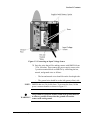
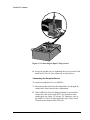
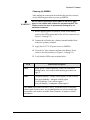
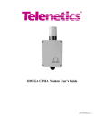
Ω OMEGA Communications Interface Cabinet Model No. OM-AMPS-100 (including Model No. OM-MP8-100 8-Port Module Option and Model No. OM-BAT-100 Battery Option) Installation, Operation, and Maintenance Manual 0049−0706−000 B The products and programs described in this User’s Guide are licensed products of Telenetics Corporation. This User’s Guide contains proprietary information protected by copyright, and this User’s Guide and all accompanying hardware and documentation are copyrighted. Telenetics Corporation does not warrant that the hardware will work properly in all environments and applications, and makes no warranty and representation, either implied or expressed, with respect to the quality, performance, merchantability, or fitness for a particular purpose. Information in this User’s Guide is subject to change without notice and does not represent a commitment on the part of Telenetics Corporation. Telenetics Corporation assumes no responsibility for any inaccuracies that may be contained in this User’s Guide. Telenetics Corporation makes no commitment to update or keep current the information in this User’s Guide, and reserves the right to make changes to this User’s Guide and/or product without notice. No part of this manual may be reproduced or transmitted in any form or by any means, electronic or mechanical, including photocopying, recording, or information storage and retrieval systems, for any purpose other than the purchaser's personal use, without the express written permission of Telenetics Corporation. Copyright 2001 Telenetics Corporation. 25111 Arctic Ocean Lake Forest, California 92630 Tel: (949) 455-4000 Fax: (949) 455-4010 Table of Contents PREFACE ............................................................................................................... 7 Product Overview...................................................................................................................7 Ancillary Documentation .......................................................................................................9 SECTION 1 INSTALLATION ............................................................................... 11 Introduction ..........................................................................................................................13 Hardware Features................................................................................................................13 Finding a Suitable Location .................................................................................................14 Avoiding Hazards.................................................................................................................15 Installing OMEGA ............................................................................................................... 15 Unpacking............................................................................................................................15 Required Materials and Tools..............................................................................................16 Mounting OMEGA..............................................................................................................16 Mounting an Antenna ..........................................................................................................17 Connecting the Input Voltage Source ..................................................................................18 Connecting the Endpoint Device .........................................................................................20 Powering Up OMEGA ........................................................................................................21 Verifying the Cellular Transceiver Unit ..............................................................................22 Operating OMEGA ..............................................................................................................22 Activating Your Cellular Transceiver..................................................................................22 Call Origination Testing ......................................................................................................22 Call Answer Testing ............................................................................................................23 SECTION 2 TROUBLESHOOTING ..................................................................... 25 Troubleshooting ...................................................................................................................27 Checking the Main Power Supply........................................................................................27 Checking the Antenna ..........................................................................................................28 Checking the Battery Voltage ..............................................................................................28 Reinitializing OMEGA ........................................................................................................28 SECTION 3 SPECIFICATIONS ............................................................................ 29 Specifications .......................................................................................................................31 Operation .............................................................................................................................31 Modem Interface..................................................................................................................31 Cellular Transceiver Interface..............................................................................................32 Battery Operation ................................................................................................................32 Switches and LED Indicators ..............................................................................................33 Power Supply.......................................................................................................................33 Mechanical Specifications ...................................................................................................34 OMEGA Operation, and Maintenance Manual iii Table of Contents Connectors ...........................................................................................................................34 Environmental Specifications ..............................................................................................34 Agency Compliance.............................................................................................................35 SECTION 4 USING THE CONFIGURATION PROGRAM.....................................37 Introduction .......................................................................................................................... 39 Prerequisites ......................................................................................................................... 39 Getting Started...................................................................................................................... 40 Reading the Cellular Telephone Signal................................................................................ 41 Programming a Telephone Number ..................................................................................... 42 Entering the Cellular Telephone’s SID ................................................................................ 43 Changing the Login Password.............................................................................................. 43 Exiting the Configuration Program ...................................................................................... 44 SECTION 5 EXTERNAL ANTENNA GUIDELINES...............................................45 Introduction .......................................................................................................................... 47 General Guidelines............................................................................................................... 47 High Voltage Areas ............................................................................................................. 47 RF Signal .............................................................................................................................47 Gain .....................................................................................................................................47 External Antenna Selection Criteria..................................................................................... 48 Antenna Placement ..............................................................................................................48 Distance from the Antenna to the Closest Cell Site .............................................................48 Degrees of Down-tilt on the Cell Site Antenna Array .........................................................48 Obstacles between the Antenna and Cell Site......................................................................48 Electrical Interference..........................................................................................................49 Distance from the Antenna to OMEGA...............................................................................49 Height Above Ground Level of the Antenna .......................................................................49 Cable for Connecting the Antenna to OMEGA ...................................................................49 Types of External Antennas ................................................................................................. 50 Directional Antenna.............................................................................................................50 Elevated Feed 3dB Gain Antenna........................................................................................50 Determining the Best External Antenna Location ............................................................... 51 Contact Information ............................................................................................................. 51 APPENDIX A 8-PORT EXPANSION MODULE OPTION......................................53 Introduction .......................................................................................................................... 55 Package Contents ................................................................................................................. 55 Field Installation................................................................................................................... 55 Testing the Module Ports ..................................................................................................... 58 Connecting Endpoint Devices.............................................................................................. 58 Time Delay Method (Automatic Connection) .....................................................................58 Second Dial Tone Method (Manual Connection) ................................................................59 iv OMEGA Installation, Operation, and Maintenance Manual Table of Contents Specifying a Default Port .....................................................................................................60 Anti-streaming......................................................................................................................61 Command Summary.............................................................................................................62 APPENDIX B WARRANTY & COMPLIANCES.................................................... 63 Warranty and RMA Statement .............................................................................................65 FCC Statement .....................................................................................................................67 FCC Interference Statement.................................................................................................67 FCC Part 15 Statement ........................................................................................................67 Comments About This Manual ............................................................................................68 INDEX.................................................................................................................... 69 OMEGA Installation, Operation, and Maintenance Manual v Table of Contents Notes vi OMEGA Installation, Operation, and Maintenance Manual P Preface This User’s Guide describes how to install, operate, and troubleshoot the Telenetics OMEGA Communications Interface Cabinet. OMEGA is a state-of-the-art, highly integrated communication interface devices. The Telenetics OMEGA family of Communication Interface Cabinets are highly integrated units that provide the functions required to link a single or multiple remote endpoint devices (such as meters, RTUs, and protective relays) to a central host computer. Communication links between OMEGA and the host computer can be provided by conventional land line or wireless cellular transceivers. Product Overview OMEGA is a standalone, single-channel unit that provides a wireless cellular connection for using an endpoint device equipped with an internal dial-line modem (see Figure P-1). The connection’s data rate depends on the type of modem at the endpoint device and the quality of the cellular connection. Telenetics offers an optional 8-port module for OMEGA which provides connection for up to eight endpoint devices equipped with an internal dial-line modem. The optional 8-port module is ideal for locations such as apartment complexes or strip malls that have multiple endpoint devices. For more information, please contact Telenetics. OMEGA Operation, and Maintenance Manual 7 Preface Figure P-1. OMEGA Application OMEGA is a fully integrated package consisting of a 3 Watt cellular transceiver, telephone-line interface, low-profile antenna, 90 to 264VAC power supply, and maintenance-free, rechargeable power back-up battery. The enclosure is made from impactresistant polycarbonate and is NEMA 4X certified. The following list summarizes OMEGA’s features. c Telephone-line interface emulation for an endpoint device equipped with an internal modem. c Optional 8-port module for connecting up to eight endpoint devices equipped with an internal dial-line modem. c Cellular transceiver for providing an analog channel to a modem at the host location. c Large-capacity rechargeable battery for providing back-up power to the cellular transceiver. c High-isolation voltage power-supply unit (8 K Volts). 8 OMEGA Installation, Operation, and Maintenance Manual c Wide-range input voltage switching power supply (90 to 277 VAC). c Standard built-in directional antenna; optional directional external antenna. c Impact-resistant, NEMA 4X non-metallic enclosure. Ancillary Documentation In addition to this manual, the OMEGA documentation suite includes the following additional documents: c OMEGA Communications Interface Cabinet Quick Start Guide (Telenetics part number 0049-0706-002) c OMEGA External Antenna Mounting Kit Installation Guide (Telenetics part number 0049-0706--005) c OMEGA 8-Port Line-Sharing Module Model OM-MP8-100 Quick Start Guide (Telenetics part number 0049-0706-001) OMEGA Installation, Operation, and Maintenance Manual 9 Preface Notes 10 OMEGA Installation, Operation, and Maintenance Manual Section 1 Installation Section 1 Contents Hardware Features............................... 13 Finding a Suitable Location ................ 14 Avoiding Hazards................................ 15 Installing the OMEGA ........................ 15 Operating the OMEGA ....................... 22 OMEGA Installation, Operation, and Maintenance Manual 11 Section 1 Contents 12 OMEGA Installation, Operation, and Maintenance Manual Section 1 Contents 1 Introduction This section describes how to install the OMEGA communications interface cabinet. Hardware Features Figure 1-1 shows the hardware features of OMEGA. The Battery and Battery Power Switch are options that can be ordered from Telenetics. Figure 1-1. OMEGA OMEGA Operation, and Maintenance Manual 13 Section 1 Contents Finding a Suitable Location Because OMEGA is a wireless solution, it is not possible to predict how it will perform in all given environments. However, observing the following guidelines will help optimize performance in your environments and applications. c Selecting a location for installing OMEGA. − The location must provide adequate cellular coverage and signal strength (preferably –90 dBm or better). It is quite common that in certain locations such as basements, belowstreet-level locations, and between hills and rural areas, the receive signal might be inadequate for cellular communications. In these cases, use an optional YAGI or elevated-feed antenna to improve reception (see Section 5 for more information). You can use the OMEGA configuration application to evaluate the cellular telephone’s receive signal strength (see Section 4). − Be sure there is sufficient space for OMEGA to connect to the endpoint device. This distance should not exceed 500 feet. − Make sure there is sufficient space to work. The space should be dry, away from overhead water pipes and free of airborne contaminants. − The location should place OMEGA within six feet of a properly grounded AC outlet. c Remote antenna installation. If you will be using a remotely located antenna, locate the antenna 10 feet above ground level and no more than 50 feet from the OMEGA unit (the shorter the distance, the better). Section 5 provides details about the external antenna installation process. c Avoid radio-frequency interference. Consider the environment’s radio-frequency characteristics, including construction materials and the presence of windows and ducting. The radio-frequency field pattern may be influenced by nearby metal objects such as appliances, equipment, and metal wall framing. 14 OMEGA Installation, Operation, and Maintenance Manual Section 1 Contents c Installing multiple OMEGA units. To avoid mutual interference when installing more than one OMEGA allow a minimum of four feet between OMEGA units. Avoiding Hazards When considering locations for installing OMEGA, avoid the following hazards. c Locations that prevent you from opening the OMEGA enclosure completely, or prevent you from accessing and viewing the OMEGA components. c Locations that expose OMEGA to the elements, including direct sunlight, rain, snow, and extreme humidity. While your OMEGA is ruggedized for extreme environments, we recommend that the location you select does not expose OMEGA to harsh conditions. c Locations prone to radio-frequency or electro-magnetic interference from devices such as security gates, garage doors, and microwave ovens. c Water or other fluids that surround OMEGA or its cellular transceiver antenna. Installing OMEGA After you select a suitable location for OMEGA, obtain cellular telephone service for OMEGA’s cellular transceiver. Then use the following procedures to install OMEGA. Unpacking The OMEGA package contains the following items: c One OMEGA unit c A diskette containing the OMEGA configuration program (described in Section 4) c This manual c A Quick Start Guide OMEGA Installation, Operation, and Maintenance Manual 15 Section 1 Contents Required Materials and Tools You need the following materials to install the OMEGA unit: c Either screws or bolts to attach OMEGA to a mounting surface. c Washers to fit with the screws or bolts. c A ¾-inch plywood backplate if the mounting surface is dry wall. Have the following tools available for installing the OMEGA unit: c Appropriate tools for the hardware you are using to mount the unit (for example, a screwdriver and wrench). c Flex–type conduit if you are installing the unit outside. c Optional: a telephone handset. In addition to the tools above, the OMEGA cellular phone must be activated, either by Telenetics or a cellular service provider. If Telenetics does not activate the OMEGA cellular phone, use the supplied OMEGA configuration program or the optional OmegaMate to configure the phone’s electronic serial number (ESN) and phone number. Mounting OMEGA Mount and secure OMEGA to a wall or panel using the supplied fasteners (see Figure 1-2). Any additional hardware required to mount OMEGA on a wall or panel must be user-supplied. NOTE: Your OMEGA may look different than the one in Figure 1-2. 16 OMEGA Installation, Operation, and Maintenance Manual Section 1 Contents Washer Screw Wall Box Side view Back view Figure 1-2. Mounting OMEGA Mounting an Antenna If your OMEGA does not have an antenna preinstalled. 1. Remove the nylon nut at the base of the antenna. You will use this nut to secure the antenna to OMEGA. Do not remove the washer located between the nut and the antenna. 2. Open the OMEGA enclosure and insert the antenna wire through the OMEGA antenna hole. Then rest the antenna on the OMEGA antenna hole. The bottom of the antenna should protrude through the antenna hole. 3. Attach the antenna wire to the SMA connector on the OMEGA transceiver. 4. Hold the cone part of the antenna with one hand. Then use your other hand to fasten the nut to the bottom of the antenna protruding through the antenna hole. This will secure the antenna to the OMEGA enclosure. OMEGA Installation, Operation, and Maintenance Manual 17 Section 1 Contents IMPORTANT: Be sure the nut is aligned with the top of the OMEGA enclosure. If the nut is not parallel to the top of the enclosure, the OMEGA top cover will not close completely. Connecting the Input Voltage Source The following procedure describes how to connect OMEGA to an input voltage source of 90 - 277 VAC. When making this connection, use a UL-listed and approved power cord with a rating of 10 amps or above. The OMEGA enclosure is pre-drilled with a hole that is .875 inches in diameter. This hole is used to accommodate a standard AC power cord and the conduit for the power cable running between the power source and the OMEGA unit. 1. Lift the AC fuse connector to turn off AC power to OMEGA (see Figure 1-1 on page 13). Do not close this AC fuse connector when connecting the input voltage source. 2. Insert the power cord through the conduit hole at the bottom of the compartment (see Figure 1-3). 18 OMEGA Installation, Operation, and Maintenance Manual Section 1 Contents Figure 1-3. Connecting an Input Voltage Source 3. Strip the wires that will be making contact with OMEGA from .25 to .40 inches. Then connect the power supply source to the 3-position terminal block on OMEGA by connecting the hot, neutral, and ground wires as follows: - The hot and neutral wires should be on the fused right side. - The ground wire should be on the left (green/yellow) side. NOTE: OMEGA has two 2A slo-blo fuses. To accesses the fuses, lift the power connector handles as shown in Figure 1-3. The ground wire between OMEGA and earth ground must be WARNING! as short as possible. Ensure that the ground wire makes contact with earth ground. OMEGA Installation, Operation, and Maintenance Manual 19 ER PO W ST AT US Section 1 Contents Figure 1-4. Connecting an Input Voltage Source 4. Secure the ground wires by tightening the screws located in the small holes of the AC fuse connectors, as shown above. Connecting the Endpoint Device To connect an endpoint device to OMEGA: 1. Insert the modem cable from the endpoint device through the conduit hole at the bottom of the compartment. 2. If the OMEGA 8-Port Line-Sharing Module is not installed, connect the cable to the single RJ-11 jack located near the conduit hole (see Figure 1-1 on page 13). Otherwise, refer to the OMEGA 8-Port Line-Sharing Module Quick Start Guide (Telenetics part number 0049-0706-001). 20 OMEGA Installation, Operation, and Maintenance Manual Section 1 Contents Powering Up OMEGA After making the connections described in the previous sections, use the following procedure to power up OMEGA. Do not remove the antenna from OMEGA and never apply WARNING! power to the cellular unit without the antenna attached. The cellular transceiver may be permanently damaged by an unloaded transmitter. 1. Before applying power to OMEGA set the Power Battery switch to the OFF position and lift the AC fuse connector (see Figure 1-1 on page 13). 2. Connect the red lead to the + battery terminal and the black lead to the − battery terminal. 3. Apply the 90-277 VAC power source to OMEGA. 4. Close the AC fuse connector and move the Battery Power switch to the ON position (see Figure 1-1 on page 13). 5. Verify that the LEDs react as shown below. LED Status and Description Power Steady green = normal operation. If this LED indicates a different status, refer to the troubleshooting procedures on page 27. Status Fast green blinking = strong cellular signal (-90 dB or better). Slow green blinking = adequate cellular signal. Fast red blinking = poor cellular signal.* Slow red blinking = inadequate cellular signal.* If the Status LED blinks red fast or slowly, it indicates a poor or unusable cellular signal. In these cases, we recommend that you use an external highgain antenna, such as those available from Telenetics, to improve cellular performance. OMEGA Installation, Operation, and Maintenance Manual 21 Section 1 Contents Verifying the Cellular Transceiver Unit To verify that the cellular transceiver unit is working and communicating with the cellular service tower, confirm that the Status LED is blinking rapidly (twice a second or faster). This indicates that the cellular unit is receiving a strong signal. If the Status LED is OFF or blinking slowly (once a second or slower), the cellular unit is receiving a weak signal. OMEGA might not transmit and receive data reliably if the cellular signal is weak. In this case, relocate OMEGA to a different location to improve cellular performance. You can also replace the OMEGA antenna with an external high-gain antenna that complies with the OMEGA specifications to improve reception, without jeopardizing the OMEGA warranty. Contact Telenetics for more information. Operating OMEGA After you set up OMEGA, use the procedures in this section to test OMEGA’s originate and answer capabilities. WARNING! Before you perform the following call-origination and callanswering procedures, replace and hand-tighten the OMEGA cover. Otherwise, the antenna can interfere with OMEGA’s performance. Activating Your Cellular Transceiver To operate OMEGA the cellular transceiver must be activated for service. To activate the cellular transceiver, contact your cellular service and provide them with the OMEGA electronic serial number (ESN). The ESN is located on the bar code on the OMEGA cellular transceiver. The ESN is an 11-digit number that starts with 236 (i.e., 236-xxxxxxxx). IMPORTANT: The cellular phone number must be available to complete the following procedures. Call Origination Testing If the OMEGA 8-Port Line-Sharing Module is installed, use the call-testing procedures in the OMEGA 8-Port Line-Sharing Module Quick Start Guide. Otherwise, use the following procedure 22 OMEGA Installation, Operation, and Maintenance Manual Section 1 Contents and the one after it to test OMEGA’s ability to originate and answer calls. IMPORTANT: If reception is poor, place the cover on OMEGA to shield the transmission from radiating energy to the transceiver. To test OMEGA’s ability to originate a call: 1. Disconnect the external modem from the OMEGA RJ-11 modem jack. 2. Connect a standard telephone to the OMEGA RJ-11 modem jack. This jack is located on the side opposite the cellular transceiver connector (see Figure 1-1 on page 13). 3. Use the telephone to dial a call. If you make a connection, it indicates that the OMEGA cellular transceiver can originate calls. NOTE: The modem that came with the endpoint device may provide additional ways to test the modem’s dial-out capabilities. Refer to the manual that came with the modem for more information. Call Answer Testing To test OMEGA’s ability to answer a call: 1. With the telephone connected to the OMEGA modem RJ-11 jack, use another telephone to call OMEGA. The telephone attached to OMEGA should ring. 2. Remove the telephone and reconnect the endpoint device to the modem jack connection on OMEGA. Have a remote modem call OMEGA. The modem connected to OMEGA should answer the call automatically. If the modem fails to automatically answer the calls, make sure the modem used with the endpoint device is configured for autoanswer (refer to the manual that came with the modem for more information). OMEGA Installation, Operation, and Maintenance Manual 23 Section 1 Contents Notes 24 OMEGA Installation, Operation, and Maintenance Manual Section 2 Troubleshooting Section 2 Contents Checking the Main Power Supply....... 27 Checking the Antenna ......................... 28 Checking the Battery Voltage ............. 28 Reinitializing the OMEGA.................. 28 OMEGA Operation, and Maintenance Manual 25 Section 2 Contents 26 OMEGA Installation, Operation, and Maintenance Manual Section 2 Contents 2 Troubleshooting This section describes troubleshooting procedures to follow in the unlikely event you encounter a problem with OMEGA. The following procedure summarizes the steps to follow to troubleshoot OMEGA. 1. Check the main power supply (see “Checking the Main Power Supply,” below). 2. Verify that the cellular transceiver is operating properly (see “Call Origination Testing” on page 22 and “Call Answer Testing” on page 23). 3. Verify that the antenna is operating (see “Checking the Antenna” on page 28). 4. For OMEGA units equipped with the Battery option, verify that the battery voltage is working properly (see “Checking the Battery Voltage” on page 28). 5. Verify that OMEGA can originate calls (see “Call Origination Testing” on page 22). 6. Verify that OMEGA can answer calls (see “Call Answer Testing” on page 23). Checking the Main Power Supply To check the main power supply: 1. Unplug the main power at the source. Then check the two fuses under the safety cover (see Figure 1-1 on page 13). If you need to replace them, use the identical type of fuse (2 Amp SLOBLO). 2. Check that the wires are securely connected to the terminal block. 3. Set OMEGA’s AC power to ON (see Figure 1-1 on page 13). 4. With AC power applied to OMEGA verify that the green Power LED is ON. Use a Voltmeter to check the DC voltage. OMEGA Installation, Operation, and Maintenance Manual 27 Section 2 Contents The voltage between the red and black terminals of the battery should be between +12.5 and +14.0 Volts. Checking the Antenna Make sure the antenna is securely fastened to the OMEGA cellular transceiver. Hand-tighten the antenna to ensure that it is securely connected to the transceiver. If it is, use the procedures under “Call Origination Testing” on page 22 and “Call Answer Testing” on page 23 to verify antenna operation. Checking the Battery Voltage If your OMEGA contains the Battery option, use the following procedure to check the battery operation: 1. Move the Battery Power switch to the OFF position (see Figure 1-1 on page 13). 2. Lift the AC fuse connector to remove AC power from OMEGA. 3. Check the voltage between the red and black terminals at the battery (see Figure 1-1 on page 13). The voltage should be approximately +12.5 to 13.0 Volts. This is the Voltage output of the battery without the load. 4. Move the Battery Power switch to ON and check the voltage again. The voltage should be between +12.0 and 12.5 Volts with the load. If the voltage for the battery terminal is below 11.5 Volts, the battery will need to be recharged or replaced. Reinitializing OMEGA There may be times when you need to initialize OMEGA. For example, you may want to reinitialize OMEGA in hopes of obtaining better cellular reception. To initialize OMEGA, press the Test button. This resets OMEGA and checks OMEGA’s receive cellular signal strength for approximately one minute. During this time, OMEGA is inoperable and cannot originate or answer calls. 28 OMEGA Installation, Operation, and Maintenance Manual Section 3 Specifications Section 3 Contents Operation............................................. 31 Modem Interface ................................. 31 Cellular Transceiver Interface............. 32 Battery Operation ................................ 32 Switches and LED Indicators.............. 33 Power Supply ...................................... 33 Mechanical Specifications................... 34 Connectors........................................... 34 Environmental Specifications ............. 34 Agency Compliance ............................ 35 OMEGA Operation, and Maintenance Manual 29 Section 3 Specifications OMEGA Operation, and Maintenance Manual 30 Section 3 Specifications Specifications 3 This section describes the OMEGA specifications. Operation OMEGA is designed to connect a remote end point device equipped with an internal modem to a head end computer when a conventional land line is not available. The interface of the modem within the endpoint device must meet PSTN and FCC-68 requirements and be compatible with all standard TELCO handshake signaling. Modem Interface A standard RJ-11 modular jack connector provides the OMEGA’s modem interface. The connection is a standard 2-wire dial line interface that has the following specifications: Output ring frequency: 18 ± 2 Hz Ring voltage: 70 volts peak to peak Maximum ringer’s equivalent: 2.0 B Dial tone frequency: 450 Hz +/- 50 Hz Dial tone level: 1.0 Volts +/- 20% ON/Off-hook current detection: >4 ma DTMF detection: Yes Pulse dialing support: Not supported OMEGA Operation, and Maintenance Manual 31 Section 3 Specifications Cellular Transceiver Interface The cellular transceiver meets the AMPS standard and conforms to the specifications below: Model number: Wireless Link CVDM-3 with data and voice interface module Operating Frequency: 824 to 893.9 MHz Number of Channels: 832 Operating voltage: 10.9 to 14.5 volts DC current requirements: power, 100 ma @ stand-by 1.5 amp @ max. transmit RF output power: 3.0 Watts maximum Antenna impedance: 50 ohms Antenna type: 50 ohm, Omni-directional VSWR is 1:2.0 or better over operating frequency Battery Operation OMEGA is equipped with a maintenance-free rechargeable battery for continuous operation without interruption in the event that power to OMEGA is disabled. 32 Battery type: Rechargeable, Lead-Acid, maintenance free Nominal output voltage: 12.0 to 12.8 Volts Charge voltage: 13.2 to 13.8 Volts Current capacity: 1.2 amp-hours minimum at 25° C Expected operation life: 5 years Operating temperature: -40 to +70° C OMEGA Installation, Operation, and Maintenance Manual Section 3 Specifications Switches and LED Indicators Toggle switches and LED indicators are provided for installation, configuration, and troubleshooting. Switch controls: AC power ON-OFF Battery ON-OFF LED Indications: LED 1: AC Power/Battery Condition LED 2: Cellular Connection Status Power Supply The switching power supply is designed to operate from a wide range of AC input voltages and is isolated against voltage transients. AC power input: 90 to 277 VAC, 50 to 60 Hz DC power input: 100 to 150 VDC Output DC voltage: 13.2 volt DC +/- 5%, full load Maximum output current: 2.0 amperes Power consumption: Idle: 1.3 Watts Transmit @ 3 Watts: 16.5 Watts Primary to secondary insulation: 8,000 volts peak at 60 Hz Battery charge voltage: 13.8 Volts Input AC fuse rating: 2 amps Slow Blow, 250V Primary surge protection: 1500 Watt-seconds Secondary surge protection: 20 KvA OMEGA Installation, Operation, and Maintenance Manual 33 Section 3 Specifications Mechanical Specifications OMEGA is designed for indoor and outdoor installation. The enclosure is made of impact-resistant polycarbonate and provides NEMA 4X watertight protection. Mounting feet are provided for surface mounting. Dimensions: 7.75” high (over antenna) x 7.0” wide x 4.75” deep Mounting Centers: 7.50” x 7.50” (adjustable, horizontal or vertical) Weight: 4.0 lbs. Protection: NEMA 4X, watertight, dust-tight Flammability Rating: UL94-5V Color: Light gray Connectors AC Power Connector: Fuse holder screw terminal block 22 – 10 AWG Device Connector: RJ-11 modular jack, 2-Wire Tip/Ring Battery Terminal: .187-inch, pushon Antenna: SMA connector (factory connected) Environmental Specifications 34 Operating Temperature: -30 to + 70o C Storage Temperature: -40 to +85o C Operating Humidity: 5 to 90 % non-condensing OMEGA Installation, Operation, and Maintenance Manual Section 3 Specifications Agency Compliance EMI/RFI: FCC-15 Class A computing devices UL: UL 1950 Surge Protection: IEC 801-4 OMEGA Installation, Operation, and Maintenance Manual 35 Section 3 Specifications Notes 36 OMEGA Installation, Operation, and Maintenance Manual Section 4 Using the Configuration Program Section 4 Contents Prerequisites ...................................................39 Getting Started................................................40 Reading the Cellular Telephone Signal..........41 Programming a Telephone Number ...............42 Changing the Cellular Telephone’s SID ........43 Changing the Login Password........................43 Exiting the Configuration Program ................44 OMEGA Operation, and Maintenance Manual 37 Section 4 Using the Configuration Program OMEGA Operation, and Maintenance Manual 38 Section 4 Using the Configuration Program Introduction 4 OMEGA comes with a configuration software program that lets you: c Check the OMEGA’s cellular telephone receive signal strength. c Program a telephone number into OMEGA. c Change the System ID (SID) for the OMEGA’s cellular telephone. c Set or change the login password. This chapter describes how to use the configuration software program to perform these tasks. Prerequisites Before you use the OMEGA configuration software program, you must: c Have a PC equipped with a Microsoft Windows operating system or MS-DOS. c Have a cable with a male DB9 connector on one end for attaching to the OMEGA serial port; the connector on the other end attaches to a serial port on your computer. c Know the communications (COM) port used by your computer’s serial port. c Contact your local cellular service provider for OMEGA’s cellular telephone phone number and SID number. OMEGA Operation, and Maintenance Manual 39 Section 4 Using the Configuration Program Getting Started To begin the OMEGA configuration process: 1. In your computer’s floppy drive, insert the floppy diskette containing the OMEGA configuration program. Then create a new folder on your computer’s hard drive and copy all of the files from the OMEGA configuration diskette to that folder. NOTE: Remember the name of the folder that contains the OMEGA configuration program. You will need to access this folder later in this procedure. 2. Connect a data cable with a male DB9 connector to OMEGA’s serial port (see Figure 1-1 on page 13). 3. Connect the other end of the cable to your notebook computer’s serial port. 4. Apply 115 VAC power to OMEGA (see “Powering-up OMEGA” on page 21). The green Power LED goes ON. 5. Exit to an MS-DOS window: c If your computer is running Windows 95 or 98, click the Start button on the taskbar and click Programs and MSDOS prompt. c If your computer is running a different operating system, refer to the manual that came with the computer for instructions on getting to a DOS prompt. 6. Change to the directory (folder) where you copied the OMEGA configuration program file. For example, if you copied the files to a directory called OMEGA type the bold command in the following line at the MS-DOS prompt and press the Enter key: C:\WINDOWS>CD\OMEGA 7. Type cvdm and press Enter. The OMEGA configuration program prompts you for a COM port (see Figure 4-1). 40 OMEGA Installation, Operation, and Maintenance Manual Section 4 Using the Configuration Program Figure 4-1. COM Port Prompt 8. Type the COM port number assigned to your computer’s serial port (for example, 1) and press Enter. The following menu appears. Figure 4-2. Main Menu From this menu, you can: c Read the cellular telephone’s receive signal see “Reading the Cellular Telephone Signal,” below. c Program a telephone number into the OMEGA cellular telephone see “Programming a Telephone Number” on page 42. c Quit the program see “Exiting the Configuration Program” on page 44. Reading the Cellular Telephone Signal The OMEGA configuration program uses a bar graph as a visual indication of the cellular telephone’s receive signal strength. Using this feature, you can see whether the OMEGA’s cellular telephone is in an area where cellular reception is strong or weak. 1. With the Main Menu in Figure 4-2 displayed, press 1 at the ? prompt. A bar graph similar to the one in Figure 4-3 appears, showing the receive signal strength of the OMEGA’s cellular telephone. The value shown to the left of the signal bar shows the receive signal level. A value of –80 or above indicate a strong signal. A value of –90 is normal. Values lower than -90 (such as –100 or –110) indicate a weak signal. OMEGA Installation, Operation, and Maintenance Manual 41 Section 4 Using the Configuration Program Figure 4-3. Example of Signal Bar 2. To exit this mode and return to the Main Menu, press the Esc key. Programming a Telephone Number Use the following procedure to program a telephone number into the OMEGA’s cellular telephone. 1. From the Main Menu in Figure 4-2, press 2. The message Waiting for response… appears, then the configuration program prompts you for a password (see Figure 4-4). Figure 4-4. Password Prompt 2. Type the password and press Enter. Initially, there is no password, so press Enter without typing any characters. The message Checking password… appears followed by the secondary menu (see Figure 4-5). Figure 4-5. Secondary Menu 3. At the ? prompt, press 2. The configuration program prompts you for a new telephone number. 4. Type the 10-digit telephone number (area code and telephone number). You do not have to press Enter after typing. The message Updating phone number… appears followed by Phone number updated! Then the secondary menu reappears with the new telephone number displayed. 42 OMEGA Installation, Operation, and Maintenance Manual Section 4 Using the Configuration Program 5. Verify that the telephone number displayed above the secondary menu is the one you entered. Entering the Cellular Telephone’s SID To enter the System ID number for your local cellular service provider, use the following procedure. 1. If the secondary menu in Figure 4-4 is not displayed, perform steps 1 and 2 under “Programming a Telephone Number” on page 42. 2. At the ? prompt, press 3. The configuration program prompts you for a new SID (see Figure 4-6). Figure 4-6. New SID Prompt 3. Type the 5-digit SID. You do not have to press Enter after typing. The message Updating SID appears, followed by SID updated! Then the secondary menu reappears with the new SID displayed. 4. Verify that the SID displayed above the secondary menu is the one you entered. Changing the Login Password By default, the OMEGA configuration program does not require you to type a password when you log in. If you desire, you can use the following procedure to password-protect the configuration. 1. If the secondary menu in Figure 4-4 is not displayed, perform steps 1 and 2 under “Programming a Telephone Number” on page 42. 2. At the ? prompt, press 1. The configuration program prompts you for a new password (see Figure 4-7). Figure 4-7. New Password Prompt OMEGA Installation, Operation, and Maintenance Manual 43 Section 4 Using the Configuration Program 3. Type the new password. The password can contain up to eight alpha and/or numeric characters. If you type fewer than eight characters, press Enter. The configuration program prompts you to re-enter the new password you typed. NOTE: For security purposes, each password character you type appears as an asterisk (*). 4. Re-enter the same password you typed in the previous step and press Enter. The message Updating password… appears followed by Password updated. After you change the password, you will need to specify it before you can log in to the OMEGA configuration program. To return to the default setting of no password, repeat this procedure but press the Enter key in steps 3 and 4 without typing any characters. NOTE: If the password you type in step 4 is different than the one you typed in step 4, the message Password mismatch appears and the new password does not take effect. If this happens, repeat this procedure, making sure to type the same characters in steps 3 and 4. Exiting the Configuration Program To exit the OMEGA configuration program: 1. From the secondary menu, press Q at the ? prompt. The message Please wait… appears followed by the Main Menu. 2. At the ? prompt, press Q again. You exit the OMEGA configuration program and return to an MS-DOS prompt. 3. If your computer is running a Windows operating system, you can close the MS-DOS window by typing exit and pressing Enter. 44 OMEGA Installation, Operation, and Maintenance Manual Section 5 External Antenna Guidelines Section 5 Contents General Guidelines.........................................47 External Antenna Selection Criteria...............48 Types of External Antennas ...........................50 Programming a Telephone Number ...............51 Contact Information .......................................51 OMEGA Operation, and Maintenance Manual 45 Section 5 External Antenna Guidelines 46 OMEGA Installation, Operation, and Maintenance Manual Section 5 External Antenna Guidelines Introduction 5 This section provides guidelines about using an external antenna with OMEGA. If you will not be using an external antenna, you can skip this section General Guidelines The following guidelines provide general topics about using an external antenna with your OMEGA. High Voltage Areas To avoid any damage, serious injury, or possible death, never install an antenna near high-voltage power lines. Telenetics recommends that you provide lightning protection for all external antennas. RF Signal Antennas cannot amplify an radio-frequency signal. Rather, they are designed to concentrate the radiated signal in a specific pattern or focus it in a particular direction. The range of an antenna can be increased by concentrating or focussing the signal. Gain An antenna’s gain is one of its identifying characteristics. Terms such as unity gain, 3dB gain, and 9dB gain are common. The amount of gain of an antenna is based on that of a true omnidirectional antenna. This type of antenna radiates the transmitted signal in all directions. If the radiated power were visible, it would resemble a sphere encompassing the antenna. An omni-directional antenna is described as having unity gain. A 3dB gain antenna has a greater range. This type of antenna is also referred to as omni-directional because the signal is transmitted in all directions. However, the signal is concentrated in a horizontal plane, so instead of a spherical “image”, its radiated power image resembles a disk. With this type of RF signal concentration, a 3watt 3dB gain antenna has the equivalent range of a 6-watt unity gain antenna and is said to have 6 watts of Effective Radiated Power (E.R.P.). OMEGA Installation, Operation, and Maintenance Manual 47 Section 5 External Antenna Guidelines NOTE: Doubling the E.R.P. does not double the range of an antenna. External Antenna Selection Criteria The following sections identify the factors to consider when selecting the type and location of external antenna to use with your OMEGA unit. Antenna Placement The method and quality of the antenna installation impact the clarity and reliability of cellular signal reception and transmission. Always strive for optimal antenna placement. Distance from the Antenna to the Closest Cell Site Find out the locations of all nearby cell sites. This information will help you position the antenna for maximum performance. Contact the local cellular carrier to obtain this information. Degrees of Down-tilt on the Cell Site Antenna Array Contact the local cellular carrier to find out this figure. The greater the down-tilt, the closer your antenna should be to the cell site or the higher gain antenna you need. Obstacles between the Antenna and Cell Site Natural obstacles such as mountains, hills, and trees between the antenna and cell site can cause signal deterioration. In some instances, the signal can be blocked completely. To compensate for natural obstacles, move the antenna location, raise the antenna height, or use a higher gain antenna. Man-made obstacles can also affect cellular performance. Check the path between the antenna and the cell site for tall buildings, water towers, and other construction. To compensate for manmade obstacles, move the antenna location, raise the antenna height, or use a higher gain antenna are ways. 48 OMEGA Installation, Operation, and Maintenance Manual Section 5 External Antenna Guidelines Electrical Interference Never locate an antenna near high voltage power lines. In addition, take into account any other sources of possible electrical interference such as AC power lines, radio-frequency generators, and other antennas. Distance from the Antenna to OMEGA Determine this distance by checking the signal strength. Start your check with the antenna located as close to the OMEGA unit as possible, using the shortest possible cable length. If you do not get a high-quality connection, try other locations. For example, you might get best results by attaching the antenna to the outside of a building, farther from the OMEGA unit, but with less obstructions between it and the cell site. Height Above Ground Level of the Antenna Always elevate the antenna as high as possible, so it has the clearest possible path to the cell site. Cable for Connecting the Antenna to OMEGA Lay the connecting cable as straight as possible without kinks, bends, or twists. If you need to keep the cable coiled, use as large a radius for the coil as possible. Keep in mind that although the maximum distance between the OMEGA unit and the external antenna is 50 feet, the distance between the OMEGA unit and the meter/telephone equipment it serves can be over 1,000 feet. The OMEGA unit does not have to be near the meter/telephone equipment to work. This factor gives you more flexibility in selecting the best antenna location. When the installation location is within the range of the cell site, a unity gain or 3dB gain antenna is usually sufficient to produce a good quality cellular connection. If the antenna installation is on the fringe of the cell site’s range or outside that range, consider using a high gain directional antenna to achieve an acceptable connection. If you cannot find an antenna location that results in a good quality connection, you might have to relocate the entire installation. Before doing so, however, try to access a different cell site through the use of a high-gain directional antenna. Even though the new OMEGA Installation, Operation, and Maintenance Manual 49 Section 5 External Antenna Guidelines cell site might be farther away, the fact that the signal is coming from a different direction might avoid natural or man-made obstacles that blocked the signal from reaching the previous antenna location. Types of External Antennas The following sections describe the various external antennas that can be used with OMEGA. Directional Antenna A directional antenna is usually best for a fixed installation. The signal from this type of antenna is focussed in one direction. Directional antennas can be designed to have different beam widths –– wide, medium, or narrow. The narrower the beam width, the higher the antenna’s gain. Directional antennas must be pointed directly at the cell site. We recommend you use directional antennas designed to provide the maximum E.R.P. allowed by FCC regulations and EIA standards. Contact the cellular carrier in your area to determine the exact location of the nearest cell site. To install a directional antenna: c Find the location of the nearest cell site that services your area. c Attach the antenna to the appropriate connector on the OMEGA unit, making sure the connection is secure. c Point the antenna toward the cell site. c Make sure the bars on the antenna are positioned vertically. c Make sure that the antenna perimeter is clear of objects, especially metal ones, that might interfere with the signal transmission and reception. Elevated Feed 3dB Gain Antenna Elevated feed antennas are designed to handle most cellular installations. There are a number of different ways to mount the antenna that will result in adequate signal strength for data applications in most area. Note that this type of antenna does not require a ground plane. 50 OMEGA Installation, Operation, and Maintenance Manual Section 5 External Antenna Guidelines Follow these guidelines when you install the antenna: c Mount the antenna as high as possible. c Try to mount the antenna with a direct line of “vision” to the nearest cellular site. c Place the antenna vertically on a solid surface. c Be sure that the antenna perimeter is clear of objects, especially metal ones, that might interfere with the signal transmission and reception. Determining the Best External Antenna Location Regardless of which type of external antenna you use, reception and propagation patterns vary with the location. To achieve the best results, try different locations. Even if a location appears adequate, you should try other locations in case you find a better one. Once you find the best location, permanently mount the antenna there. Use the OMEGA configuration application to evaluate the cellular telephone’s receive line signal strength and ascertain the best external antenna location. When the signal strength is –90 or higher, you have achieved a minimum acceptable cellular signal. Contact Information If you need technical assistance or information about various antenna products, contact Telenetics at the following number: (949) 455-4000. OMEGA Installation, Operation, and Maintenance Manual 51 Section 5 External Antenna Guidelines Notes 52 OMEGA Installation, Operation, and Maintenance Manual Appendix A 8-Port Expansion Module Option Appendix A Contents Package Contents ................................... 55 Field Installation...................................... 55 Testing the Module Ports ........................ 58 Connecting Endpoint Devices.................58 Specifying a Default Port ........................60 Anti-streaming.........................................61 Command Summary................................62 OMEGA Operation, and Maintenance Manual 53 Appendix A 8-Port Expansion Module Option 54 OMEGA Installation, Operation, and Maintenance Manual Appendix A 8-Port Expansion Module Option Introduction A An optional eight-port expansion module, Model OM-MP8-100, is available for OMEGA. This expansion module allow up to eight endpoint devices (such as meters, relays, and controllers) with internal modems to connect to a single OMEGA Model OM-AMPS-100 Cellular Interface Cabinet. This appendix describes how to install the expansion module. For more information about the expansion module, please contact Telenetics. Package Contents The 8-Port Expansion Module package contains the following items: c One OMEGA 8-Port Expansion Module (Model Number. OM-MP8-100) c Two plastic card guides c One short RJ-11 to RJ-11 cable c A diskette containing configuration software c A Quick Start Guide If any of these items are missing or damaged, please contact Telenetics immediately. Field Installation The eight-port expansion module is designed for simple installation in the field. Use the following procedure to install the module. 1. Set the Power Battery switch to the OFF position and lift the AC fuse connector (see Figure 1-1 on page 13). 2. Orient the two plastic card guides so their slots face inward toward each other. Snap the guides into place in the holes in the OMEGA baseboard. OMEGA Installation, Operation, and Maintenance Manual 55 Appendix A 8-Port Expansion Module Option 3. Insert the cable clip into the round hole next to the relays labeled K2 and K3 on the component side of the Module. Use this cable clip to route and arrange cables within the OMEGA unit. 4. Hold the Module vertically above the card guides, so its 8 RJ11 jacks are at the top and facing toward the inside of OMEGA. 5. Insert the Module into the card guide slots and slide it down until the male connector engages fully into the female connector on the OMEGA baseboard (see Figure A-1). This installation can only be made one way. If you are not successful with your first try, turn around the Module and try again. Firgure A-1. Sliding the Module into the Card Guides 56 OMEGA Installation, Operation, and Maintenance Manual Appendix A 8-Port Expansion Module Option 6. Press down the Module gently until it snaps securely into the card guide connectors (one on each card guide). 7. Insert one end of the supplied short cable into the RJ-11 jack on the lower-left side of the Module. Insert the other end into the OMEGA unit’s RJ-11 jack on the unit’s baseboard (see Figure A-2). Figure A-2. Connecting the RJ-11 Jacks 8. Plug in all the RJ-11 cables from the external devices (see 5, “Connecting Endpoint Devices” on page 58). 9. Set the OMEGA Power Battery switch to the ON position and close the AC fuse connector. Verify that each LED above the 8 RJ-11 jacks on the Module turns green. This color indicates that the meter ports are onhook and ready for operation. OMEGA Installation, Operation, and Maintenance Manual 57 Appendix A 8-Port Expansion Module Option Testing the Module Ports After you install the Module, test each port on the Module: 1. Connect a handset to one of the RJ-11 jacks on the Module. 2. Lift the handset and listen for a dial tone. 3. Verify that the LED above the jack remains green, while the LEDs for the other 7 ports turn red. 4. Repeat this procedure for the remaining Module ports. Connecting Endpoint Devices Connect an endpoint device to the Module’s RJ-11 jack labeled J1 (which corresponds to port 1). Connect the remaining endpoint devices to any of the other RJ-11 jacks. A remote host can communicate with one endpoint device at a time using either of the following methods. In both cases, the connection is maintained until the host or meter ends it. When a host connects to an endpoint device, the LED above the port being called remains green. The LEDs for all other ports turn red to show that they are “locked out” until the host goes on-hook. You can also connect a phone to the OMEGA’s RJ-11 jack to originate and receive calls as you would normally. The host can communicate with an endpoint device in two ways: using the Time Delay method or the Second Dial Tone method. Time Delay Method (Automatic Connection) With this method, the host computer calls OMEGA and waits for a connection. When connected, the host sends a DTMF digit that corresponds to a number from 1 to 8 on a touch-tone telephone or via a modem. This number corresponds to the port with which the host wants to communicate. For example, sending the DTMF digit 4 corresponds to port 4. When OMEGA is configured for the time delay method, the host issues the following dial string: ATDT<phone number>,,,<port number> <Enter> In this string: c <phone number> is the OMEGA phone number (and area code, if required). 58 OMEGA Installation, Operation, and Maintenance Manual Appendix A 8-Port Expansion Module Option c Each comma represents a 2-second pause. c <port number> is the port number with which the host wants to communicate. c <Enter> is the pressing of the Enter key on your computer. Example: ATDT 19495552468,,,4 <Enter> In this example, OMEGA dials 1 949 555-2468, waits 6 seconds to allow a connection, and connects the line to port 4. Second Dial Tone Method (Manual Connection) With this method, the host computer calls OMEGA and waits for a “second” dial tone from OMEGA. The second dial tone signals the host to enter the DTMF tone that corresponds to an OMEGA port. To enable this method, connect a laptop computer to OMEGA’s DB-9 connector, start a terminal-emulation program such as HyperTerminal, set up the program to use the parameters on page 62, and send the following command from the program: \PR=1 <Enter>. When OMEGA is configured for the second dial tone method, the host issues the following dial string: ATDT<phone number>W,,<port number> <Enter> In this string: • <phone number> is the OMEGA phone number (and area code, if required). • W indicates that the host is to wait for the second dial tone. • • • Each comma represents a 2-second pause. <port number> is the port number with which the host wants to communicate. <Enter> is the pressing of the Enter key on your computer. Example: ATDT 19495552468W,,6 <Enter> To switch from the second dial tone method to the time delay method, use a laptop computer connected to OMEGA’s DB-9 connector to send the following command from a terminalemulation program: \PR=0 <Enter> OMEGA Installation, Operation, and Maintenance Manual 59 Appendix A 8-Port Expansion Module Option Specifying a Default Port There may be times when you want to specify a default OMEGA port. Specifying a default port enables the host to automatically contact the same OMEGA port with each call. This feature is convenient, for example, if you want to connect to a telephone set at the OMEGA site. To enable a default port, connect a laptop computer to OMEGA’s DB-9 connector, start a terminal-emulation program such as HyperTerminal, set up the program to use the parameters on page 62, and send the following command from the program: \PD=<port number> <Enter> In this command, <port number> is a port number from 1 to 8 you want to specify as the default port. Example: Specifying OMEGA port 4 as the default port: \PD=4 <Enter> When OMEGA is configured with a default port, the host can dial OMEGA using the dial string for either the Time Delay method or the Second Dial Tone method; however, the port number must be omitted from the string. Time delay example: ATDT 19495552468,,, <Enter> Second dial tone example: ATDT19495552468W,, <Enter> When OMEGA is configured with a default port and receives a dial string with no port number, it waits 10 seconds and then automatically routes the call to the default port specified by the command: \PD=<port number> <Enter> To disable a default port, use a laptop computer connected to OMEGA’s DB-9 connector to send the following command from a terminal-emulation program: \PD=0 <Enter> 60 OMEGA Installation, Operation, and Maintenance Manual Appendix A 8-Port Expansion Module Option Anti-streaming OMEGA provides an anti-streaming feature that deactivates OMEGA ports that are off-hook but have not dialed out for 12 seconds. Anti streaming deactivates the ports that are off-hook, without affecting any of the OMEGA ports that are on-hook. This enables the on-hook OMEGA ports to function normally. The deactivated ports are reactivated when any of the following actions occurs: c An incoming call selects that port using a DTMF tone. c OMEGA is powered-up locally. c The OMEGA Reset button is used to reset the unit. c OMEGA is reconfigured. Note: If a port stays on-hook after a bad train and remote disconnect, the port is deactivated, which places the OMEGA modem on-hook. After two minutes, the port is reactivated automatically if the modem is still on-hook. To enable anti streaming, connect a laptop computer to OMEGA’s DB-9 connector, start a terminal-emulation program such as HyperTerminal, set up the program to use the parameters on page 62, and send the following command from the program: \PS=1 <Enter> To disable anti streaming, connect a laptop computer to OMEGA’s DB-9 connector and send the following command from a terminalemulation program: \PS=0 <Enter> OMEGA Installation, Operation, and Maintenance Manual 61 Appendix A 8-Port Expansion Module Option Command Summary To… Do the Following… Prepare for terminal-emulation mode Start a terminal-emulation program such as at a laptop computer. HyperTerminal and specify the following parameters: Data rate: 9600 bps Data bits: 8 Parity bit: None Stop bit: 1 Specify <port number> as the default port number. Type \PD=<port number> and press <Enter> Disable default port operation. Type \PD=0 and press <Enter> Enable second dial tone method. Type \PR=1 and press <Enter> Disable second dial tone method, returning OMEGA to the time delay method. Type \PR=0 and press <Enter> Enable anti-streaming. Type \PS=1 and press <Enter> Disable anti-streaming. Type \PS=0 and press <Enter> 62 OMEGA Installation, Operation, and Maintenance Manual Appendix B Warranty & Compliances Appendix B Contents Warranty and RMA Statement ................ 65 FCC Statement ........................................ 67 Comments About This Manual ............... 68 OMEGA Operation, and Maintenance Manual 63 Appendix B Warranty & Compliances 64 OMEGA Installation, Operation, and Maintenance Manual Appendix B Warranty & Compliances B This appendix provides warranty and RMA information, along with FCC compliance information, and steps to follow if you have comments about or corrections to this manual. Warranty and RMA Statement Subject to the conditions and procedures set forth below and for one year after the date of shipment by Telenetics, Telenetics will repair or replace, at Telenetics' option, such Telenetics products or parts thereof or software which, on inspection by Telenetics, are found to be covered by the limited warranties set forth below. If you think there is a problem or defect with your Telenetics internetworking product or software: c c c c Contact Telenetics' Technical Support Department between 8:00 a.m. and 5:00 p.m., Pacific Time at (949) 455-4000 or via fax at (949) 455-4010. The Telenetics Technical Support Representative will discuss your problem to confirm the defect. After business hours, please leave a voicemail. A Technical Support Representative will respond to you the next business day. If warranty or return service is needed, you will receive a Return Material Authorization (RMA) number. At no time should Telenetics products or software be sent back without a valid RMA number. Telenetics accepts no responsibility for unauthorized returns. You agree to pay for shipping to Telenetics. If the product is under warranty, Telenetics will pay for shipping the repaired or replacement products to you. All Telenetics-paid shipments to customers will be by ground transportation. Any other freight arrangements will be at customer expense. Telenetics shall not be liable for any damage caused to the product in transit. You acknowledge and agree that you will bear all risk of loss or damage to the product while in transit. Send return shipments to: Telenetics Corporation 25111 Arctic Ocean Lake Forest, California 92630 ATTN: RMA # ______________________ c c c Pack products securely, to prevent damage in transit. Be sure the RMA number is clearly visible on the outside of the return shipping carton. Returned Telenetics products must include all other components from the original package, including the hardware, any cables, connectors, and user manual(s) unless otherwise stipulated by Telenetics. Enclose a copy of the original purchaser’s proof of purchase, if needed to support warranty claim. (See details in LIMITATIONS on the next page.) After inspecting the failed unit, Telenetics will repair or replace defective parts or components. If upon inspection by Telenetics, a unit returned under warranty is deemed to be damaged or out of warranty for any reason, (see LIMITATIONS section on the next page), Telenetics will contact the customer with a price for the repair or replacement unit. Upon receipt of payment (wire transfer, certified check, credit card, etc.) for the replacement unit plus outbound shipping fees, Telenetics will send a new refurbished unit to the customer. Customers who do not accept the repair offer may receive their failed equipment back by prepaying the return freight cost. In selected circumstances, determined by Telenetics in its sole judgment, Telenetics will ship advance replacement for defective products within two business days of the approved RMA request provided that the product is in stock. All Telenetics-paid shipments to customers will be by OMEGA Installation, Operation, and Maintenance Manual 65 Appendix B Warranty & Compliances ground transportation. Any other freight arrangements will be at customer expense. Customers who receive this advance-replacement service shall, prior to the shipment of the advanced shipment product, c Provide a credit card number or hard copy purchase order as collateral for the loaned product. c Sign an RMA agreement outlining the terms and conditions of the exchange. c Agree to return the defective product to Telenetics within five (5) business days of receipt of the advance replacement unit. If, upon inspection by Telenetics, a unit returned under warranty is found to be defect free, Telenetics reserves the right to charge the customer a $500 test fee. TELENETICS' SOLE AND EXCLUSIVE OBLIGATION, AND YOUR SOLE AND EXCLUSIVE REMEDY, UNDER THIS LIMITED WARRANTY SHALL BE THE REPAIR OR REPLACEMENT OF THE APPLICABLE TELENETICS PRODUCT OR SOFTWARE IN ACCORDANCE WITH THE TERMS SET FORTH HEREIN. LIMITATIONS As the original purchaser, you receive these warranties from Telenetics Corporation, subject to the terms and limitations set forth below. Telenetics warrants that your Telenetics products will be free from defects in material and workmanship and will perform in compliance with the operator’s guide(s) accompanying the products for a period of one year. Telenetics does not cover or accept liability for any injury, damage or failure caused by misuse, misapplication, abuse, acts of nature, accidents (e.g., dropping the Telenetics products or software diskettes), electrical mishaps, causes beyond our control, or claims by other than the original purchaser. Telenetics will not honor, and will consider this limited warranty voided, if, in Telenetics' reasonable judgment, there has been any (1) tampering with the Telenetics product's external label or serial number, (2) attempt to open the Telenetics product's case, (3) attempted or actual repair by anyone other than an authorized Telenetics technician, or (4) installation or use with any power supply component(s) other than the original Telenetics power supply components provided in the product package, (5) installation or use with any cables or antenna(s) other than original Telenetics products, (6) Installation or use in environmental conditions that are outside Telenetics’ published environmental specifications (including but not limited to temperature range, humidity, cable lengths, proximity to other devices, etc.). Warranty is given for twelve (12) months from the date of product shipment from Telenetics. Telenetics will honor warranty twelve months from the original end user’s shipment date, upon receiving proof of purchase. “Proof of purchase” is a copy of the original sales transaction, showing complete name and address of seller, complete name and address of purchaser, date of purchase, product model number and serial number(s). DISCLAIMER OF WARRANTIES EXCEPT AS EXPRESSLY SET FORTH HEREIN, TELENETICS HEREBY EXPRESSLY DISCLAIMS ANY AND ALL WARRANTIES, EXPRESS OR IMPLIED, INCLUDING WITHOUT LIMITATION THE IMPLIED WARRANTIES OF MERCHANTABILITY OR FITNESS FOR A PARTICULAR USE. WAIVER OF CONSEQUENTIAL DAMAGES TELENETICS HEREBY DISCLAIMS ANY AND ALL SPECIAL, INDIRECT, OR CONSEQUENTIAL DAMAGES (INCLUDING WITHOUT LIMITATION, LOST PROFITS, LOSS OF OR DAMAGE TO ANY OTHER COMPUTER EQUIPMENT OR RELATED DATA) WHICH MAY RESULT FROM BREACH OF ANY WARRANTY, OR ARISING OUT OF THE USE OR INABILITY TO USE ANY TELENETICS PRODUCT OR SOFTWARE, EVEN IF TELENETICS HAS BEEN ADVISED OF THE POSSIBILITY OF SUCH DAMAGES. 66 OMEGA Installation, Operation, and Maintenance Manual Appendix B Warranty & Compliances FCC Statement The following sections contain FCC compliance information about your OMEGA unit. FCC Interference Statement This equipment has been tested and found to comply with the limits for a Class A Digital Device pursuant to Part 15 of the FCC Rules. These limits are designed to provide reasonable protection against interference if installed and operated properly in a commercial environment. This equipment generates, uses and can radiate radio frequency energy. If not properly installed and used in accordance with the instructions in this manual, harmful interference can be caused to radio communications. Operation of this equipment in a residential area is likely to cause interference in which case the user will be required to correct the interference at their expense. FCC Part 15 Statement This device complies with Part 15 of the FCC Rules. Operation is subject to the following two conditions: (1) this device may not cause harmful interference, and (2) this device must accept any interference received, including interference that may cause undesired operation. This equipment has been tested and found to comply with the limits for a Class A digital device, pursuant to Part 15 of the FCC Rules. These limits are designed to provide reasonable protection against harmful interference in a residential installation. This equipment generates, uses, and can radiate radio frequency energy and, if not installed and used in accordance with the instructions, may cause harmful interference to radio communications. However, there is no guarantee that interference will not occur in a particular installation. If this equipment does cause harmful interference to radio or television reception, which can be determined by turning the equipment off and on, the user is encouraged to try to correct the interference by one or more of the following measures: c c c c Reorient or relocate the receiving antenna. Increase the separation between the equipment and the receiver. Connect the equipment to an outlet on a circuit other than the one to which the receiver is connected. Consult the dealer or an experienced radio/TV technician for help. If none of these actions resolves the problem, consult your distributor or an experienced radio/television technician for additional suggestions. Additionally, Section 15.838, paragraph d), of the FCC Rules and Regulations states: “Where special accessories, such as shielded cables, are required in order to meet FCC regulations, shielded cables must be used with this equipment. Operation with nonapproved equipment or unshielded cables is likely to result in interference to radio and TV reception. The user is cautioned that changes and modifications to this equipment without the approval of the manufacturer could void the user’s authority to operate this equipment. OMEGA Installation, Operation, and Maintenance Manual 67 Appendix B Warranty & Compliances Comments About This Manual Telenetics invites all customers to communicate with us about any question or comment related to this manual. Just fax, phone, or mail any question or comment to us. Your suggestions help us improve the products we deliver. Telenetics Corporation. 25111 Arctic Ocean Lake Forest, California 92630 Tel: (949) 455-4000 Fax: (949) 455-4010 68 OMEGA Installation, Operation, and Maintenance Manual INDEX A Activating cellular transceiver, 22 Agency compliance, 35 Anti-streaming, 61 Avoiding hazards, 15 B Battery operation, 32 Best external antenna location, 51 C Call answer testing, 23 Cellular telephone SID changing, 43 cellular telephone signal, 41 Cellular transceiver activating, 22 Cellular transceiver interface, 32 Cellular transceiver unit, 22 Changing cellular telephone SID, 43 login password, 43 Checking antenna, 28 battery voltage, 28 main power supply, 27 Comments about manual, 68 Compliance, 35 Connecting endpoint devices, 58 Connecting the input voltage source, 18 Connectors, 34 Exiting the configuration program, 44 External antenna best location, 51 directional, 50 elevated feed, 50 general guidelines, 47 selection criteria, 48 types, 50 F FCC Interference Statement, 67 Part 15 Statement, 67 Finding a suitable location, 14 H Hardware features, 13 I Input voltage source, 18 Installation eight-port expansion module, 55 OMEGA, 15 Interfaces cellular transceiver, 32 modem, 31 L LED indicators, 33 Locating an external antenna, 51 Login password changing, 43 D Default port, specifying, 60 Directional external antennas, 50 Drilling conduit holes, 16 Drilling mounting holes, 16 M Manual comments, 68 Mechanical specifications, 34 Modem interface, 31 Mounting, 16 E Eight-port expansion module field installation, 55 operation, 58 overview, 55 Elevated feed external antennas, 50 Environmental specifications, 34 OMEGA Operation, and Maintenance Manual O OMEGA avoiding hazards, 15 call answer testing, 23 drilling conduit holes, 16 drilling mounting holes, 16 69 INDEX finding a suitable location, 14 hardware features, 13 input voltage source connection, 18 installation, 15 mounting instructions, 16 operation, 22 power-up, 21 specifications, 62 OMEGA configuration program changing the cellular telephone SID, 43 changing the login password, 43 exiting, 44 getting started, 40 prerequisites, 39 programming a telephone number, 42 reading the cellular telephone signal, 41 Operation, 22, 31 SID P T Password changing, 43 Power supply, 33 Power-up, 21 Prerequisites for OMEGA configuration program, 39 Programming a telephone number, 42 Telephone number programming, 42 Time delay method, 58 Troubleshooting, 27 antenna, 28 battery voltage, 28 main power supply, 27 R Reading the cellular telephone signal, 41 RMA, 65 changing, 43 Signal for cellular telephone, 41 Specifications, 31, 39, 47, 62 agency compliance, 35 battery operation, 32 cellular transceiver interface, 32 connectors, 34 environmental, 34 LED indicators, 33 mechanical, 34 modem interface, 31 operation, 31 power supply, 33 switches, 33 Specifying a default port, 60 Switches, 33 V Verifying the cellular transceiver unit, 22 S W Second dial tone method, 59 Selecting an external antenna, 48 Warranty, 65 70 OMEGA Installation, Operation, and Maintenance Manual