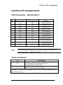
1
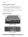
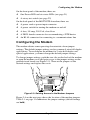
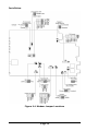
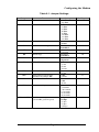
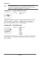
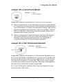
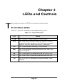
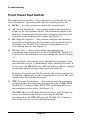
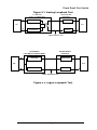
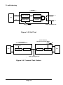
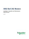
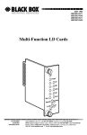
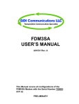
MOT202TSA/MOT202TRM Modem User’s Guide 0049-0119-000, Rev. A Contents CHAPTER 1 INTRODUCTION .........................................................5 SUMMARY OF KEY FEATURES .................................................................5 MODELS ...................................................................................................6 USING THIS MANUAL ..............................................................................6 CONTACT INFORMATION .........................................................................7 CHAPTER 2 INSTALLING THE MODEM .....................................9 SITE PREPARATION ..................................................................................9 UNPACKING YOUR HARDWARE ...............................................................9 ADDITIONAL ITEMS YOU NEED .............................................................10 HARDWARE OVERVIEW .........................................................................10 CONFIGURING THE MODEM ...................................................................11 Jumper S1 − Carrier Detect Control ................................................14 Jumper S2 − Transmit Level .............................................................14 Jumper S3 − 2-wire/4-wire Mode .....................................................15 Jumper S4 − Call Turnaround Squelch.............................................15 Jumper S5 − Transmit Carrier..........................................................16 Jumper S6 − Local Copy ...................................................................16 Jumper S8 − Signal and Earth Ground.............................................16 Jumper S9 − RTS-CTS Delay ............................................................17 Jumper S10 − Carrier Detect Delay .................................................17 Jumper S11 − Turnaround Squelch Time .........................................17 Jumper S12 − Soft Carrier Turn Off .................................................18 Jumper S13 − Anti-Streaming ...........................................................18 Jumpers S14 and S15 − Self Test or Test Pattern .............................19 CONNECTING A DTE..............................................................................19 CONNECTING TO A PRIVATE LINE COMMUNICATION CIRCUIT ..............19 Connecting to an AC Power Source .................................................19 Powering-on the Modem...................................................................20 Powering-off the Modem...................................................................20 Page iii Contents CHAPTER 3 LEDS AND CONTROLS ........................................... 21 FRONT PANEL LEDS ............................................................................. 21 FRONT PANEL TEST SWITCH ................................................................. 22 CHAPTER 4 TROUBLESHOOTING ............................................. 25 LOCAL MODEM TEST ............................................................................ 25 LINE AND MODEM TEST ........................................................................ 26 CHAPTER 5 SPECIFICATIONS..................................................... 27 GENERAL............................................................................................... 27 DIMENSIONS AND WEIGHT .................................................................... 28 TEMPERATURE RANGE .......................................................................... 28 POWER REQUIREMENTS ........................................................................ 28 INTERFACE PIN ASSIGNMENTS .............................................................. 29 DTE Connector - EIA RS-232-C ...................................................... 29 Telco Connector ............................................................................... 29 APPENDIX A COMPLIANCES....................................................... 31 APPENDIX B LIMITED PRODUCT WARRANTY ..................... 33 APPENDIX C, RMA PROCEDURE................................................ 35 Page iv Chapter 1 Introduction T he Telenetics MOT202TSA standalone modem and MOT202TRM rack-mount modem are Frequency Shift Keyed (FSK) modems designed for asynchronous half-duplex communication on 2-wire private line circuits or full-duplex communication on 4-wire private-line circuits. Summary of Key Features The following list summarizes the modem’s key features. • Bell 202T compatible • Operates over voice-grade leased lines or private lines • 0 to 1200 bps operation for unconditioned line. • 0 to 1800 bps operation for conditioned line (C2). • Point-to-point or point-to-multipoint polling network • 4-wire full-duplex or 2-wire half-duplex leased-line configuration. • Analog Loopback Test, Digital Loopback Test, Self Test, and Test Pattern Transmit. • LED displays for power, RS-232 control, data status, and test mode. Page 5 Introduction Models The Telenetics modem is available in two models: c The MOT202TSA is a desktop modem. c The MOT202RTM is a rack-mount modem that installs into a standard 19-inch rack. In this manual, the term “modem” will be used to refer to both models collectively. If information pertains to one model only, that model will be identified by its model number. Using This Manual This manual contains all the information you need to install, configure, use, and test your modem. c Chapter 1 contains general information on what the 202T modem does, contents of this manual, and contact information for Telenetics. c Chapter 2 describes how to install and configure the modem. c Chapter 3 provides general operating procedures. c Chapter 4 provides troubleshooting procedures. c Chapter 5 lists the modem’s specifications. Page 6 Contact Information Contact Information For more information about Telenetics’ MOT202TSA and MOT202TRM modems, or other Telenetics solutions, please contact us using any of the following methods. Voice Calls We welcome your calls at (949) 455-4000 Monday through Friday, from 8:00 am to 5:00 pm Pacific Time. Fax Number You can also send your requests for information to our 24-hour fax number: (949) 455-4010. E-mail If you prefer, you can send information requests to our 24-hour e-mail address: [email protected]. Website Our website contains valuable information about our products. We encourage you to visit us online at www.telenetics.com. Page 7 Introduction NOTES Page 8 Chapter 2 Installing the Modem T his chapter describes how to install the modem. Site Preparation The location where you install your modem should be: • Within six feet of a 115 or 230 VAC grounded outlet not controlled by a wall switch • No more than 50 feet from the data terminal equipment • Away from extremes of temperature, humidity, and appreciable shock. Note: Be sure that there is a 4-inch minimum space at the back of the modem for signal line and interface cable clearance. Unpacking Your Hardware Your package should include at least one MOT202TSA or MOT202TRM modem, one RJ-45 jack-to-4 wire leased line cable, and this Installation Guide. If your package contents are damaged or missing, please contact your place of purchase immediately. Page 9 Installation Additional Items You Need To use your modem, you need the following additional items: c All users: an RS-232 cable to connect a data terminal. The cable must conform to the pin assignments shown on page 29. c Standalone modem users: a two- or four-wire transmission line or leased line and power supply. c Rack-mount modem users: a modem rack and an available slot in the rack for installing the modem. Hardware Overview Figures 2-1 and 2-2 show the front and back modem panels. Figure 2-1. Front Panel Figure 2-2. Back Panel Page 10 Configuring the Modem On the front panel of the modem, there are: c One Power LED and six status LEDs (see page 21) c A rotary test switch (see page 22) On the back panel of the MOT202TSA modem, there are: c A power cord or power input connector c A power switch for turning the modem on and off c A fuse, 3/8 amp, 250 Volt, slow-blow c A DB25 female connector for accommodating a DTE device c An RJ-45 connector for connecting to a communications line Configuring the Modem The modem obtains some operating characteristics from jumper settings. The default jumper settings are for common 4-wire full-duplex applications. To reconfigure the modem for 2-wire half-duplex and special applications, you must change the default jumper settings. To change jumper settings, push the two tabs on the back of the modem to open the modem cover and gain access to the jumper settings on the printed circuit board (see Figure 2-3). Then set the jumpers to the desired settings and replace the cover. Figure 2-3. Gaining Access to the Modem Jumpers Figure 2-4 on the next page shows the location of the modem jumpers. Table 2-1 on page 13 summarizes the jumper settings (default settings are bold). Page 11 Installation Figure 2-4. Modem Jumper Locations Page 12 Configuring the Modem Table 2-1. Jumper Settings Jumper S1 Function Carrier Detect control S2 Transmit level S3 2-wire/4-wire mode S4 Call turnaround squelch S5 Transmit carrier S6 Local copy S8 Signal and Earth ground S9 RTS-CTS delay S10 Carrier Detect delay S11 S12 Turnaround squelch time (Enabled by jumper S4) Soft Carrier turn off S13 Anti-streaming S14 and S15 Self Test or test pattern (Tx and Rx pattern speed) Page 13 Settings -33 dBm -43 dBm 0dBm -2 dBm -4 dBm -6 dBm -8 dBm -10 dBm -12 dBm -14 dBm 2-wire 4-wire Enabled Disabled Control Constant Enabled Disabled Connected Separate 8 ms 33 ms 59 ms 219 ms 6 ms 23 ms 8 ms 159 ms None 8 ms 26 ms None 4 seconds 7.6 seconds 14 seconds 28 seconds 56 seconds 1 bps 18 bps 37 bps 75 bps 150 bps See Page… 14 14 15 15 16 16 16 17 17 17 18 18 19 Installation Note: The jumper positions in the following sections reflect the position of the jumpers on the modem board when you face the board as indicated in Figure 2-4 on page 12. Jumper S1 − Carrier Detect Control Settings: -33 dBm (default) -43 dBm Jumper S1 configures the dynamic range of the modem receiver. The selections are either –33 dBm or –43 dBm. If the incoming signal is above –24 dBm, use the default –33 dBm setting. If the modem is operated on the network, use the –43 dBm setting. Jumper S2 − Transmit Level Settings: 0 dBm (default) -2 dBm -4 dBm -6 dBm -8 dBm -10 dBm -12 dBm -14 dBm Jumper S2 adjusts the modem’s transmit level. There are eight transmit level settings you can choose. By default, the modem uses a transmit level of 0 dBm. Page 14 Configuring the Modem Jumper S3 − 2-wire/4-wire Mode Settings: 2-wire 4-wire (default) Jumper S3 configures the modem for 2-wire or 4-wire operation. c When configured for 4-wire full-duplex operation, jumper S5 can be strapped to maintain constant carrier from the master modem to all slave modems at all times after the initial training. This enables the master modem to transmit data to the slave modems, with no RTS-to-CTS delay. This is the preferred operating mode when minimum turnaround is desired. c When configured for 2-wire half-duplex operation, the modem encounters an RTS-to-CTS delay when transmitting to slave modems, increasing the turnaround time. Set jumper S5 to controlled carrier for 2-wire half-duplex operation. Jumper S4 − Call Turnaround Squelch Settings: Enabled Disabled (default) Jumper S4 configures the modem’s Call Turnaround Squelch setting. For 2-wire, half-duplex communications, set this strap to the Enabled position. In this position, the receiver is inhibited for a period of time after the local transmitter is turned OFF. This guards against echoes caused by the transmission just completed. The time is determined by the turnaround squelch time option (jumper S11). For 4-wire, full-duplex communications, keep the jumper set to the default position of Disabled. Page 15 Installation Jumper S5 − Transmit Carrier Settings: Control (default) Constant Jumper S5 places the transmitter under terminal control (default) or turns on the transmitter continuously in a 2-wire half duplex system. Jumper S6 − Local Copy Settings: Enabled Disabled (default) Jumper S6 must be left is the default position of Disabled when operating on a 4-wire network. It is also normally left in the default Disabled position when operating on a 2-wire network. Strapping this jumper as Disabled inhibits the local receiver from receiving the transmission of the local transmitter. Jumper S8 − Signal and Earth Ground Settings: Connected Separate (default) Jumper S8 allows Earth GND to be tied to the modem system GND. Page 16 Configuring the Modem Jumper S9 − RTS-CTS Delay Settings: 8 ms (default) 33 ms 59 ms 219 ms Jumper S9 configures the modem’s RTS-CTS delay. Four choices for selecting an RTS-CTS delay are available. Jumper S10 − Carrier Detect Delay Settings: 6 ms (default) 23 ms Jumper S10 configures the modem’s Carrier Detect turn on Delay timing. The delay chosen must be consistent with the Clear To Send delay selection of the transmitting modem and must be less than the CTS delay. The available delays are 6 ms (default) and 23 ms. The carrier detect drop out is less than 6 ms. Jumper S11 − Turnaround Squelch Time Settings: 8 ms (default) 159 ms Jumper S11 is used with the call turnaround squelch option (jumper S4). The available times are 8 ms (default) and 159 ms. Page 17 Installation Jumper S12 − Soft Carrier Turn Off Settings: None 8 ms (default) 26 ms Jumper S12 configures the modem to either turn off the transmitter immediately upon release of Request To Send, or send a Soft Carrier Turn Off signal of 900 Hz for 8 or 26 ms at the end of each transmission. Jumper S13 − Anti-Streaming Settings: None (default) 4 seconds 7.6 seconds 14 seconds 28 seconds 56 seconds Jumper S13 lets you select an anti-streaming time or use no antistreaming at all. Anti-streaming is typically used in multi-point applications to prevent a malfunctioning slave from occupying the line indefinitely. When anti-streaming is active, the modem can only transmit data for up to 56 seconds. Thereafter, the modem’s transmitter is automatically turned off. The modem then looks for an ON-to-OFF transition of Request To Send (RTS) before proceeding with normal operation. Page 18 Connecting a DTE Jumpers S14 and S15 − Self Test or Test Pattern Settings: 1 bps 18 bps (default) 37 bps 75 bps 150 bps Jumpers S14 and S15 configures the modem for Self Test or Test Pattern. When the modem is in local Self Test or Test Pattern mode, it generates a dot test pattern. The supported baud rates are 1 bps, 18 bps, 37 bps, 75 bps, or 150 bps. Connecting a DTE The modem back panel provides a standard, 25-pin port labeled DTE, which connects to an RS-232 device. The connectors for this port conform to the pin assignments shown under “DTE Connector – EIA RS-232-C” on page 29. The DTE should have a cable no longer than 50 feet, with a Cinch or Cannon plug per DB-19604-432 plus a DB-51225-1 hood or equivalent. Connecting to a Private Line Communication Circuit The modem back panel provides an 8-pin RJ-45 connector labeled TELCO, which connects to a private line communication circuit. The connectors for this port conform to the pin assignments shown under “Telco Connector” on page 29. Connecting to an AC Power Source The modem back panel provides an AC line cord. If the chassis ground is connected through the third prong of the AC power plug, a separate chassis ground wire is required. Page 19 Installation Powering-on the Modem To supply power to the modem, place the POWER ON switch on the modem back panel to the ON position. The PWR LED on the front panel goes ON. Powering-off the Modem To turn off power to the modem, place the POWER ON switch on the modem back panel to the OFF position. The PWR LED on the front panel goes OFF. Page 20 Chapter 3 LEDs and Controls T his chapter describes the LEDs and controls on the modem. Front Panel LEDs Table 3-1 describes the LEDs on the modem front panel. Table 3-1. Front Panel LEDs LED PWR Status ON = power is being supplied to the modem. TM ON = the rotary switch is turned to Analog or Digital Loopback, or the switch is in the Test Pattern transmit mode or Self Test mode and no error is detected. CD ON = the modem is detecting a valid carrier. RD ON = data is being received or receive data line is in a space condition. RS ON = the Request-to-Send line from the DTE is ON. CS ON = the Clear-to-Send line from the modem is ON. TD ON = data to be transmitted is being furnished to the modem. Page 21 Troubleshooting Front Panel Test Switch The modem front panel has a five-position rotary switch that lets you select the modem’s operating mode. The five switch positions are: c DATA use this position for normal data transmissions. c AL (Analog Loopback) this position prepares the modem for testing by the local terminal device. The transmitter output of the modem is disconnected from the output coupling transformer and connected to the modem receiver input. See Figure 3-1. c DL (Digital Loopback) this position configures the modem to loop back received data to the transmitter and transmit the data to the remote end. The RS-232-C interface to the terminal is not active during this test. See Figure 3-2. c ST (Self Test) this position inhibits the modem from transmitting and receiving data on the COMM LINE. The RS-232C interface to the terminal is not active during this test. See Figure 3-3. The test pattern (dot pattern) passes through the transmitter, loops back into the receiver, is demodulated, and is checked for errors. If errors occur, the TM LED turns OFF and remains OFF for a period of time that depends on the pattern generator baud rate. In Analog Loopback and Self Test modes, the received analog data is buffered, amplified by 16 dB (if output level is set to 0 dB), and routed out on the transmit analog pair. c TTP (Transmit Test Pattern) this setting forces the transmitter on and transmits data from the test generator to the COMM LINE. The RS-232-C interface lines (RTS, CTS, and Transmit Data) to the transmitter are not active. See Figure 3-4. The TM LED goes ON when the receive data is good. If there are errors, or if the received data does not compare with the transmitted data, the TM LED goes off. The RS-232-C interface lines to the receiver are active during this mode. Page 22 Front Panel Test Switch Figure 3-1. Analog Loopback Test Local Modem Analog LoopBack Mode RXD Remote Modem Data Mode RECEIVER TRANSMITTER Amplifier DTE DTE PAD TXD TRANSMITTER RECEIVER 4-Wire Telephone Line Figure 1 - Analog Loopback Test Local Modem Local Digital LoopBack Mode Remote Modem Data Mode RECEIVER TRANSMITTER DTE DTE TRANSMITTER RECEIVER 4-Wire Telephone Line Digital Loopback Test Figure 3-2. Digital Loopback Test Page 23 Troubleshooting Modem Self Test Mode TEST PATTERN TRANSMITTER TX PAD DTE Amplifier ERROR CHECK RECEIVER TM RX 4-Wire Telephone Line Self Test Figure 3-3. Self Test Remote Modem Receive Test Pattern Mode Local Modem Send Test Pattern Mode TM SPEED SELECT DTE TEST PATTERN TRANSMITTER RECEIVER 2-Wire Telephone Line Transmit Test Pattern Figure 3-4. Transmit Test Pattern Page 24 ERROR CHECK DTE Chapter 4 Troubleshooting T his chapter describes troubleshooting procedures you can use in the unlikely event you encounter a problem with your modem. Local Modem Test The local modem test verifies the local modem’s transmitter, receiver, and connection to the locally attached DTE. This test can be run either by generating a data pattern from the locally attached DTE or by having the modem generate a test pattern. The following procedure describes how to run the local modem test using a locally attached DTE to generate a data pattern. 1. Using the front panel test switch, place the modem in Analog Loopback mode. 2. Turn on the Request To Send line. 3. Use the locally attached DTE to transmit the data pattern and check for data errors on the Receive Data line. The following procedure describes how to run the local modem test using the modem test pattern instead of a data pattern originated by the local DTE. 1. Using the front panel test switch, place the modem in Self Test mode. 2. The TM indicator should turn ON. If the indicator turns OFF or flashes, errors are occurring. Page 25 Specifications Line and Modem Test The line and modem test verifies the local modem, the remote modem, and the communications line between them. With this test, the local modem loops back received data to the transmitter and transmits the data to the remote modem. These characters can originate either from a locally attached DTE or by having the modem generate a test pattern. The following procedure describes how to run the line and modem test using a locally attached DTE to generate a data pattern. 1. Place the remote modem in Digital Loopback mode. 2. Place the local modem in Data mode and transmit a data pattern. Check for data errors on the Receive Data line The following procedure describes how to run the line and modem test using the modem test pattern instead of a data pattern originated by the local DTE. 1. Place the remote modem in Remote Test mode. 2. Place the local modem in Remote Self Test mode. The TM LED should turn ON and remain ON if the data is error free. Page 26 Chapter 5 Specifications T his chapter lists the specifications for the modem. General Operation: 2-wire half-duplex or 4-wire full-duplex private line operation. Data rate: 0-1200 bps asynchronous on worst case line. 0-1800 asynchronous on C2 conditioned line Modulation: Phase coherent. Frequency Shift Keyed (FSK) Carrier frequencies: Mark 1200 Hz ±1% Space 2200 Hz ±1% Line impedance: 600 ohms ±10% transformer coupled and transient protected. Transmitter output level: Selectable from 0 to –14 dBm, in 2 dB steps. RTS-CTS delay: 8, 33, 59, or 219 ms Carrier Detect delay: 6 or 23 ms OFF-to-ON, 6 On-to-OFF Digital interface: EIA RS-232-C and CCITT V.24. Package: Standalone, UL approved. Turnaround squelch: 8 ms or 159 ms Anti-streaming: Option to turn transmitter OFF after selected time, even if RTS is ON Page 27 Specifications Self Test, Analog Loopback, Digital Loopback, and Test Pattern Transmit Test features: Dimensions and Weight Width: 7.00 inches (17.8 cm) Length: 9.60 inches (24.4 cm) Height: 2.25 inches (5.7 cm) Temperature Range Operating: -40 to +85 degrees Celsius Storage: -40 to +85 degrees Celsius Humidity range:95% relative, non-condensing Power Requirements c 115 VAC + or – 10%: 50/60 Hz c 230 VAC + or – 10%: 50/60 Hz c 12 to 60 VDC For applicable models. Page 28 Interface Pin Assignments Interface Pin Assignments DTE Connector - EIA RS-232-C Pin RS-232C Circuit CCITT V.24 Circuit Function 1 AA 101 Protective Ground 2 BA 103 Transmitter Data 3 BB 104 Receive Data 4 CA 105 Request to Send 5 CB 106 Clear to Send 6 CC 107 Data Set Ready 7 AB 102 Signal Ground 8 CF 109 Data Carrier Detect 9 +12 Volts Test Only 10 -12 Volts Test Only 25 Analog Loopback Note: All interfaces on the RS-232-C digital connector conform to the requirements of EIA-RS-232-C. Telco Connector Pin Description 4, 5 2-wire mode: transmit/receive pair. 4-wire mode: transmit pair. 3, 6 Receive pair for 4-wire mode. Polarity of transmit pair or receive pair is not significant. Remaining pins are not used. Page 29 Specifications NOTES Page 30 Appendix A Compliances FCC Rule This device complies with Part 15A of the FCC Rules. Operation is subject to the following two conditions: (1) this device may not cause harmful interference, and (2) this device must accept any interference received, including interference that may cause undesired operation. This equipment has been tested and found to comply with the limits for a Class A digital device, pursuant to Part 15A of the FCC Rules. These limits are designed to provide reasonable protection against harmful interference in a residential installation. This equipment generates, uses, and can radiate radio frequency energy and, if not installed and used in accordance with the instructions, may cause harmful interference to radio communications. However, there is no guarantee that interference will not occur in a particular installation. If this equipment does cause harmful interference to radio or television reception, which can be determined by turning the equipment off and on, the user is encouraged to try to correct the interference by one or more of the following measures: c Reorient or relocate the receiving antenna. c Increase the separation between the equipment and the receiver. c Connect the equipment to an outlet on a circuit other than the one to which the receiver is connected. c Consult the dealer or an experienced radio/TV technician for help. If none of these actions resolves the problem, consult your distributor or an experienced radio/television technician for additional suggestions. Additionally, Section 15.838, paragraph d), of the FCC Rules and Regulations states: “Where special accessories, such as shielded cables, are required in order to meet FCC regulations, shielded cables must be used with this equipment. Operation with non-approved equipment or unshielded cables is likely to result in interference to radio and TV reception. The user is cautioned that changes and modifications to this equipment without the approval of the manufacturer could void the user’s authority to operate this equipment. Page 31 Compliances Department of Canada Statement This Class A digital apparatus meets all requirements of the Canadian Interference-Causing Equipment Regulations. Cet appareil numerique de la classe A respecte toutes les exigences du Reglement sur le materiel brouilleur du Canada. Page 32 Appendix B Limited Product Warranty Telenetics warrants that the Product sold will be free from defects in material and workmanship and perform to Telenetics' applicable published specifications for a period of 18 months from the date of delivery to Customer or 12 months from placement into service, whichever occurs first. The liability of Telenetics hereunder shall be limited to replacing or repairing, at its option, any defective Products which are returned F.O.B., Telenetics' facility, Lake Forest, California (or, at Telenetics' option refunding the purchase price of such products). In no case are Products to be returned without first obtaining permission and a customer return order number from Telenetics. In no event shall Telenetics be liable for any consequential or incidental damages. Products which have been subject to abuse, misuse, accident, alteration, neglect, unauthorized repair or installation are not covered by the warranty. Telenetics shall make the final determination as to the existence and cause of any alleged defect. No liability is assumed for expendable items such as lamps and fuses. No warranty is made with respect to custom products or Products produced to Customer's specifications except as specifically stated in writing by Telenetics in the agreement for such custom products. This warranty is the only warranty made by Telenetics with respect to the goods delivered hereunder, and may be modified or amended only by a written instrument signed by a duly authorized officer or Telenetics and accepted by Customer. This warranty and limitation extends to customer and to users of the product and is in lieu of all warranties with respect to the product whether express, implied, or statutory, including without limitation the implied warranties of merchantability and fitness for a particular purpose. Page 33 Limited Product Warranty NOTES Page 34