1
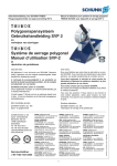
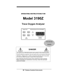
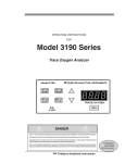
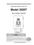
OPERATING INSTRUCTIONS FOR Model 3300PA Percent Oxygen Analyzer SERIES 3300 PERCENT OXYGEN SAMPLE SPAN Teledyne Analytical Instruments DANGER HIGHLY TOXIC AND OR FLAMMABLE LIQUIDS OR GASES MAY BE PRESENT IN THIS MONITORING SYSTEM. PERSONAL PROTECTIVE EQUIPMENT MAY BE REQUIRED WHEN SERVICING THIS SYSTEM. HAZARDOUS VOLTAGES EXIST ON CERTAIN COMPONENTS INTERNALLY WHICH MAY PERSIST FOR A TIME EVEN AFTER THE POWER IS TURNED OFF AND DISCONNECTED. ONLY AUTHORIZED PERSONNEL SHOULD CONDUCT MAINTENANCE AND/OR SERVICING. BEFORE CONDUCTING ANY MAINTENANCE OR SERVICING CONSULT WITH AUTHORIZED SUPERVISOR/ MANAGER. Teledyne Analytical Instruments P/N M69127 08/06/99 ECO # 99-0323 i Copyright © 1999 Teledyne Analytical Instruments All Rights Reserved. No part of this manual may be reproduced, transmitted, transcribed, stored in a retrieval system, or translated into any other language or computer language in whole or in part, in any form or by any means, whether it be electronic, mechanical, magnetic, optical, manual, or otherwise, without the prior written consent of Teledyne Analytical Instruments, 16830 Chestnut Street, City of Industry, CA 91749-1580. Warranty This equipment is sold subject to the mutual agreement that it is warranted by us free from defects of material and of construction, and that our liability shall be limited to replacing or repairing at our factory (without charge, except for transportation), or at customer plant at our option, any material or construction in which defects become apparent within one year from the date of shipment, except in cases where quotations or acknowledgements provide for a shorter period. Components manufactured by others bear the warranty of their manufacturer. This warranty does not cover defects caused by wear, accident, misuse, neglect or repairs other than those performed by Teledyne or an authorized service center. We assume no liability for direct or indirect damages of any kind and the purchaser by the acceptance of the equipment will assume all liability for any damage which may result from its use or misuse. We reserve the right to employ any suitable material in the manufacture of our apparatus, and to make any alterations in the dimensions, shape or weight of any parts, in so far as such alterations do not adversely affect our warranty. Important Notice This instrument provides measurement readings to its user, and serves as a tool by which valuable data can be gathered. The information provided by the instrument may assist the user in eliminating potential hazards caused by his process; however, it is essential that all personnel involved in the use of the instrument or its interface, with the process being measured, be properly trained in the process itself, as well as all instrumentation related to it. The safety of personnel is ultimately the responsibility of those who control process conditions. While this instrument may be able to provide early warning of imminent danger, it has no control over process conditions, and it can be misused. In particular, any alarm or control systems installed must be tested and understood, both as to how they operate and as to how they can be defeated. Any safeguards required such as locks, labels, or redundancy, must be provided by the user or specifically requested of Teledyne at the time the order is placed. Therefore, the purchaser must be aware of the hazardous process conditions. The purchaser is responsible for the training of personnel, for providing hazard warning methods and instrumentation per the appropriate standards, and for ensuring that hazard warning devices and instrumentation are maintained and operated properly. Teledyne Analytical Instruments (TAI), the manufacturer of this instrument, cannot accept responsibility for conditions beyond its knowledge and control. No statement expressed or implied by this document or any information disseminated by the manufacturer or its agents, is to be construed as a warranty of adequate safety control under the user’s process conditions. ii Teledyne Analytical Instruments Contents Introduction 1.1 1.2 1.3 1.4 Overview ........................................................................ 1-1 Main Features of the Analyzer ....................................... 1-1 Front Panel Description .................................................. 1-2 Rear Panel Description .................................................. 1-3 Operational Theory 2.1 Introduction .................................................................... 2-1 2.2 Micro-Fuel Cell Sensor .................................................. 2-1 2.2.1 Principles of Operation .......................................... 2-1 2.2.2 Anatomy of a Micro-Fuel Cell ................................. 2-2 2.2.3 Electrochemical Reactions .................................... 2-3 2.2.4 The Effect of Pressure............................................ 2-3 2.2.5 Calibration Characteristics ...................................... 2-4 2.3 Electronics ..................................................................... 2-5 2.3.1 General .................................................................. 2-5 2.3.2 Signal Processing .................................................. 2-5 Installation 3.1 Unpacking the Analyzer ................................................. 3-1 3.2 Location and Mounting .................................................. 3-2 3.2.1 Control Unit Installation.......................................... 3-2 3.2.2 External Probe Installation ..................................... 3-2 3.2.3 Installing the Micro-Fuel Cell ................................. 3-2 3.3 Electrical Connections ................................................... 3-3 3.4 Gas Connections ........................................................... 3-6 3.5 Installation Checklist ...................................................... 3-6 Operation 4.1 Introduction .................................................................... 4-1 4.2 Using the Function and Data Entry Buttons ................... 4-2 4.3 Setting the Analysis Ranges .......................................... 4-2 4.3.1 HI Range ............................................................... 4-2 4.3.2 LO Range .............................................................. 4-3 4.4 Setting the Alarm Setpoints............................................ 4-3 Teledyne Analytical Instruments iii 4.4.1 Alarm 1 .................................................................. 4-3 4.4.2 Alarm 2 .................................................................. 4-3 4.4.3 Sensor Fail Alarm .................................................. 4-4 4.5 Selecting a Fixed Range or Autoranging ....................... 4-4 4.6 Calibration ..................................................................... 4-4 Maintenance 5.1 Replacing the Fuse ........................................................ 5-1 5.2 Sensor Installation or Replacement ............................... 5-2 5.2.1 When to Replace a Sensor .................................... 5-2 5.2.2 Ordering and Handling of Spare Sensors .............. 5-3 5.2.3 Removing the Micro-Fuel Cell ............................... 5-3 5.2.4 Installing a Micro-Fuel Cell .................................... 5-3 5.2.5 Cell Warranty Conditions ....................................... 5-4 Appendix A.1 A.2 A.3 A.4 A.5 iv Specifications ................................................................ A-1 Spare Parts List ............................................................. A-2 Reference Drawing ........................................................ A-3 Miscellaneous ................................................................ A-3 Material Safety Data Sheet ............................................ A-3 Teledyne Analytical Instruments DANGER COMBUSTIBLE GAS USAGE WARNING This is a general purpose instrument designed for usage in a nonhazardous area. It is the customer's responsibility to ensure safety especially when combustible gases are being analyzed since the potential of gas leaks always exist. The customer should ensure that the principles of operating of this equipment is well understood by the user. Misuse of this product in any manner, tampering with its components, or unauthorized substitution of any component may adversely affect the safety of this instrument. Since the use of this instrument is beyond the control of Teledyne, no responsibility by Teledyne, its affiliates, and agents for damage or injury from misuse or neglect of this equipment is implied or assumed. Teledyne Analytical Instruments v This page left intentionally blank vi Teledyne Analytical Instruments Percent Oxygen Analyzer Introduction 1 Introduction 1.1 Overview The Teledyne Electronic Technologies Analytical Instruments (TETAI) Model 3300PA is a microprocessor-based percent oxygen analyzer for realtime measurement of the percent of oxygen in inert gases, or in a wide variety of gas mixtures. It features simple operation, fast response, and a compact, rugged construction. Typical applications of the Model 3300PA are monitoring nitrogen generators and inert gas blanketing applications. 1.2 Main Features of the Analyzer The main features of the analyzer include: • High resolution, accurate readings of oxygen content from 0-1 % through 0-25 %, with 0-100% range optional. Large, bright, lightemitting-diode meter readout. • Simple pushbutton controls. • Nylon cell holder. • Advanced Micro-Fuel Cell, for percent analysis, has a two year warranty and an expected lifetime of 3 years. • Unaffected by oxidizable gases. • Fast response and recovery time. • Microprocessor based electronics: 8-bit CMOS microprocessor with on-board RAM and 16 KB ROM. • Two user selectable ranges (from 0-1 % through 0-25 %) allow best match to users process and equipment. • Air-calibration range for convenient spanning at 20.9 %. Teledyne Analytical Instruments 1-1 1 Introduction • • • • • Model 3300PA Operator can select Autoranging, which allows the analyzer to automatically select the proper preset range for a given measurement, or he can lock the analyzer onto a single range. Two concentration alarms with adjustable setpoints. Sensor failure alarm. Three analog outputs: two for measurement (0–10 V dc, and negative ground 4–20 mA dc) and one for range identification (0-10 V dc). Compact and rugged Control Unit with flush-panel case. Designed for indoor use. 1.3 Front Panel Description All controls and displays except the power switch are accessible from the front panel. See Figure 1-1. The front panel has seven pushbutton membrane switches, a digital meter, and an alarm indicator LED for operating the analyzer. These features are described briefly here and in greater detail in Chapter 4, Operation. Figure 1-1: Front Panel Function Keys: Seven pushbutton membrane switches are used to select the function performed by the analyzer: • Set Alarm 1 Sets Alarm 1 Hi or Low, and the concentration at which alarm 1 activates. 1-2 Teledyne Analytical Instruments Percent Oxygen Analyzer • Introduction 1 Set Alarm 2 Sets the Alarm 2 Hi or Low, and the concentration to which alarm 2 activates. • Set HI Range Set the high analysis range for the instrument (up to 0-25 %). • Set LO Range Set the low analysis range for the instrument (down to 0-1 %). • Span Span calibrate the analyzer. Data Entry Keys: Two pushbutton membrane switches are used to manually change measurement parameters of the instrument as they are displayed on the LED meter readout: • Up Arrow Increment values of parameters upwards as they are displayed on the LED readout. • Down Arrow Increment values of parameters downwards as they are displayed on the LED readout. Digital LED Readout: The digital display is a LED device that produces large, bright, 7-segment numbers that are legible in any lighting environment. It has two functions: • Meter Readout: As the meter readout, it displays the oxygen concentration currently being measured. • Measurement Parameters Readout: It also displays userdefinable alarm setpoints, ranges, and span calibration point when they are being checked or changed. 1.4 Rear Panel Description The rear panel contains the electrical input and output connectors. The connectors are described briefly here and in detail in the Installation chapter of this manual. Figure 1-2 Rear Panel Teledyne Analytical Instruments 1-3 1 Introduction 1-4 Model 3300PA • Power Connection • Analog Outputs • Alarm Connections • Sensor Connector 100–240 V ac, at 50/60 Hz. The connector housing includes the fuse holder and the power switch. Fuse Holder: Replacing the fuse is described in Chapter 5, Maintenance. I/O Power Switch: Turns the instrument power ON (1) or OFF (0). 0–10 V dc concentration output. 0–10 V dc range ID (or optional overrange) output. 4–20 mA dc concentration output, negative ground. Alarm 1, Alarm 2, and Sensor Failure Alarm connections. Internal Sampling System, Sensor Connector. Teledyne Analytical Instruments Percent Oxygen Analyzer Operational Theory 2 Operational Theory 2.1 Introduction The analyzer is composed of two subsystems: 1. Analysis Unit with Micro-Fuel Cell Sensor 2. Control Unit with Signal Processing, Display and Controls The Analysis Unit is designed to accept the sample gas and direct it to the sensitive surface of the Micro-Fuel Cell sensor. The Micro-Fuel Cell is an electrochemical galvanic device that translates the amount of oxygen present in the sample into an electrical current. The Control Unit processes the sensor output and translates it into electrical concentration, range, and alarm outputs, and a percent oxygen meter readout. It contains a microcontroller that manages all signal processing, input/output, and display functions for the analyzer. 2.2 Micro-Fuel Cell Sensor 2.2.1 Principles of Operation The oxygen sensor used in the Model 3300PA is a Micro-Fuel Cell designed and manufactured by TAI. It is a sealed, disposable electrochemical transducer. The active components of the Micro-Fuel Cell are a cathode, an anode, and the aqueous KOH electrolyte in which they are immersed. The cell converts the energy from a chemical reaction into an electrical potential that can produce a current in an external electrical circuit. Its action is similar to that of a battery. There is, however, an important difference in the operation of a battery as compared to the Micro-Fuel Cell: In the battery, all reactants are stored within the cell, whereas in the Micro-Fuel Cell, one of the reactants (oxygen) comes from outside the device as a constituent of the sample gas being analyzed. The Teledyne Analytical Instruments 2-1 2 Operational Theory Model 3300PA Micro-Fuel Cell is therefore a hybrid between a battery and a true fuel cell. (All of the reactants are stored externally in a true fuel cell.) 2.2.2 Anatomy of a Micro-Fuel Cell The Micro-Fuel Cell is made of extremely inert plastic (which can be placed confidently in practically any environment or sample stream). It is effectively sealed, though one end is permeable to oxygen in the sample gas. At the permeable end a screen retains a diffusion membrane through which the oxygen passes into the cell. At the other end of the cell is a connector, and a temperature compensation network (resistors and thermistor) on a printed circuit board. Refer to Figure 2-1, Basic Elements of a Micro-Fuel Cell, which illustrates the following internal description. Electrical Connector C ircuit B oard w ith tem perature com pensation network. Anode C athode Teflon M em brane Screen C lam p Figure 2-1. Basic Elements of a Micro-Fuel Cell (not to scale) At the sensing end of the cell is a diffusion membrane, whose thickness is very accurately controlled. Near the diffusion membrane lies the oxygen sensing element—the cathode. The anode structure is larger than the cathode. It is made of lead and is designed to maximize the amount of metal available for chemical reaction. 2-2 Teledyne Analytical Instruments Percent Oxygen Analyzer Operational Theory 2 The space between the active elements is filled by a structure saturated with electrolyte. Cathode and anode are wet by this common pool. They each have a conductor connecting them, through some electrical circuitry, to one of the external contacts in the connector receptacle, which is on the top of the cell. 2.2.3 Electrochemical Reactions The sample gas diffuses through the Teflon membrane. Any oxygen in the sample gas is reduced on the surface of the cathode by the following HALF REACTION: O2 + 2H2O + 4e– → 4OH– (cathode) (Four electrons combine with one oxygen molecule—in the presence of water from the electrolyte—to produce four hydroxyl ions.) When the oxygen is reduced at the cathode, lead is simultaneously oxidized at the anode by the following HALF REACTION: 2(Pb + 2OH–) → 2(Pb+2 + H2O) + 4e– (anode) (Two electrons are transferred for each atom of lead that is oxidized. TWO ANODE REACTIONS balance one cathode reaction to transfer four electrons.) The electrons released at the surface of the anode flow to the cathode surface when an external electrical path is provided. The current is proportional to the amount of oxygen reaching the cathode. It is measured and used to determine the oxygen concentration in the gas mixture. The overall reaction for the fuel cell is the SUM of the half reactions above, or: 2Pb + O2 → 2PbO (These reactions will hold as long as no gaseous components capable of oxidizing lead are present in the sample. The only likely components are the halogens—iodine, bromine, chlorine and fluorine.) The output of the fuel cell is limited by (1) the amount of oxygen in the cell at the time and (2) the amount of stored anode material. In the absence of oxygen, no current is generated. 2.2.4 The Effect of Pressure In order to state the amount of oxygen present in the sample as a percentage of the gas mixture, it is necessary that the sample diffuse into the cell under constant pressure. Teledyne Analytical Instruments 2-3 2 Operational Theory Model 3300PA If the pressure changes, the rate that oxygen reaches the cathode through the diffusing membrane will also increase. The electron transfer, and therefore the external current, will increase, even though the proportion of oxygen has not changed. Fortunately, Dalton's Law confirms that every gas in a mixture contributes the same pressure to the mixture that it would exert if it were alone in the same amount in that same volume. This means that as long as the total pressure of the sample remains constant, the mixture can change, but the diffusion of the oxygen will be affected only by the concentration of the oxygen. For this reason, the sample system supplying sample gas to the cell should be designed to keep the pressure on the diffusion membrane constant. 2.2.5 Calibration Characteristics Given that the total pressure of the sample gas at the surface of the MicroFuel Cell input is constant, a convenient characteristic of the cell is that the current produced in an external circuit of constant impedance is directly proportional to the rate at which oxygen molecules reach the cathode, and this rate is directly proportional to the concentration of oxygen in the gaseous mixture. In other words it has a linear characteristic curve, as shown in Figure 2-2. Measuring circuits do not have to compensate for nonlinearities. Figure 2-2. Characteristic Input/Output Curve for a Micro-Fuel Cell In addition, since there is zero output in the absence oxygen, the characteristic curve has an absolute zero. The cell itself does not need to be zeroed. 2-4 Teledyne Analytical Instruments Percent Oxygen Analyzer 2.3 Operational Theory 2 Electronics 2.3.1 General The signal processing uses an Intel microcontroller with on-board RAM and ROM to control all signal processing, input/output, and display functions for the analyzer. System power is supplied from a universal power supply module designed to be compatible with most international power sources. The power supply circuitry is on the Power Supply PCB, which is mounted vertically, just behind the rear panel of the Control Unit. The signal processing electronics including the sensor amplifier, microcontroller, analog to digital, and digital to analog converters are located on the Main PCB, which is mounted vertically, just behind the front panel of the Control Unit. 2.3.2 Signal Processing Figure 2-3 is a block diagram of the signal processing electronics described below. Millivolt Potput M FC Microamp Output TE M PE RATU RE CO M PE NS AT ION NET W ORK ON S ENSO R P CB S ENSO R A M PLIFIE R ADC E –I CON V 4–20 m A dc Concentration 0–10 V dc I-22 Sensor DAC RAN GE ID M ICRO CO NT RO LLER K EY BO ARD DIS P LAY RELAYS A LAR M S RELAYS A LAR M S Figure 2-3: Block Diagram of the Signal Processing Electronics Teledyne Analytical Instruments 2-5 2 Operational Theory Model 3300PA In the presence of oxygen the cell generates a current. This current flows through an internal thermistor compensation network. The output of the sensor is converted to voltage in the millivolt range. This output is fed to a voltage amplifier. The internal thermistor network provides temperature compensation of the sensor output. The resistance of the network changes with temperature, compensating for the changes of the microfuel cell output to temperature. The output from the sensor amplifier is sent to an analog to digital converter (ADC), and the resulting digital concentration signal is sent to the microcontroller. The digital concentration signal along with input from the front panel buttons (KEYBOARD) is processed by the microcontroller, and appropriate output signals are directed to the display and alarm relays. The same digital information is also sent to a 12-bit digital to analog converter (DAC) that produces the 0-10 V dc analog concentration signal and the 0-10 V dc analog range ID output. A current to voltage converter (E–I CONV) produces the 4-20 mA dc analog concentration signal. 2-6 Teledyne Analytical Instruments Percent Oxygen Analyzer Installation 3 Installation Overvoltage Category II Installation of the analyzer includes: 1. Unpacking the system. 2. Mounting the Control Unit to a 19" Rack. 3. Installing the Micro-Fuel Cell. 4. Making the electrical connections. 5. Making the gas connections. 6. Testing the installation. CAUTIONS: Read this chapter in its entirety before installing the units. For indoor use only. The Sample must be free of entrained solids or water. However, a high humidity sample is ideal, since it will prevent water loss from the cell electrolyte. The Micro-Fuel Cell sensor electrolyte is caustic. Do not attempt to open it. Leaking or exhausted cells should be disposed of in accordance with local regulations. Refer to the Material Safety Data Sheet in the Appendix. Any damage or scarring of the delicate permeable membrane on the sensing end of the cell will require cell replacement. Prevent contact with membrane by any solid object. 3.1 Unpacking the Analyzer As soon as you receive the instrument, carefully unpack and inspect Control Unit, and any included accessories for damage. Immediately report any damage to the shipping agent. The analyzer is shipped with all the materials you need to install and prepare the system for operation. CAUTION: Do not disturb the integrity of the cell package until the cell is to actually be used. If the cell package is punctured and air is permitted to enter, cell-life will be compromised. Teledyne Analytical Instruments 3-1 3 Installation 3.2 Model 3300PA Location and Mounting 3.2.1 Control Unit Installation The 3300PA Control Unit is designed to be rack mounted in a general purpose, indoor area, away from moisture and the elements. The unit should be installed at viewing level in a sheltered area. Refer to the Outline diagram D-69220 for the physical dimensions of the analyzer. 3.2.2 Installing the Micro-Fuel Cell A Micro-Fuel Cell is included as a separate item. It must be installed prior to instrument use. Also, once it is expended, or if the instrument has been idle for a lengthy period, the Micro-Fuel Cell will need to be replaced. To install or replace the Micro-Fuel Cell, follow the procedures in Chapter 5, Maintenance. 3.3 Electrical Connections Figure 3-1 shows the Model 3300PB rear panel. For detailed pinouts, see the wiring/interconnection drawings in the Drawings section at the rear of this manual. Figure 3-1 Electrical Connectors for AC Control Unit 3-2 Teledyne Analytical Instruments Percent Oxygen Analyzer Installation 3 Primary Input Power: The power cord receptacle, fuse block and Power switch are located in the same assembly. A 6-foot, standard AC power cord is supplied with the Control Unit. Insert the female plug end of the power cord into the power cord receptacle. The universal power supply allows direct connection to any 100-240 VAC, 50/60Hz power source. The fuse block, to the right of the power cord receptacle, accepts two 3AG, 0.5 A, time-lag (T) fuse. (See Fuse Replacement in chapter 5, Maintenance.) The Power switch is located on the right-hand end of the power source input receptacle assembly. Analog Outputs: There are three DC output signal connectors with screw terminals on the panel. There are two wires per output with the polarity noted. See Figure 3-3. The outputs are: 0–10 V % Range: Voltage rises with increasing oxygen concentration, from 0 V at 0 percent oxygen to 10 V at full scale percent oxygen. (Full scale = 100% of programmed range.) 0–10 V Range ID: 03.33 V = Low Range, 06.66 V = High Range, 10 V = Air Cal Range. 4–20 mA % Range: Current increases with increasing oxygen concentration, from 4 mA at 0 percent oxygen to 20 mA at full scale percent oxygen. (Full scale = 100% of programmed range.) Alarm Relays: The three alarm-circuit connectors are screw terminals for making connections to internal alarm relay contacts. There is one set of contacts for each type of alarm. Contacts are Form C, with normally open and normally closed contact connections capable of switching up to 0.5 ampere at 125 VAC into a resistive load (2A for 30 VDC). The alarm relay circuits are designed for failsafe operation, meaning the relays are energized during normal operation. If power fails the relays deenergize (alarms activated). The contact connections are indicated diagrammatically on the rear panel as Normally Closed, Common, and Normally Open. Figure 3-2 explains how these act in failsafe operation. Alarm 1 and Alarm 2 can both be configured as either HI or LO. A HI alarm will activate when concentration is above threshold, while a LO alarm will activate when concentration is below threshold. Teledyne Analytical Instruments 3-3 3 Installation Model 3300PA Figure 3-2: Contact ID for FAILSAFE Relay Operation The specific descriptions for each type of alarm are as follows: Alarm #1 Programmable as high or low alarm. Can be set anywhere between 0 and 25 %. Alarm #2 Programmable as high or low alarm. Can be set anywhere from 0 to 25 %. Sensor Fail Actuates when the output of the Micro-Fuel Cell sensor falls below the acceptable level (0.05% O2). CAUTION: There could be hazardous voltage at the alarms terminals, even when power is removed from the instrument. Internal Sensor Wiring: The receptacle for the analysis unit cable is located in the lower left-hand corner of the rear panel. The 6-pin polarized connector is keyed to fit only one way into the receptacle. Do not force it in. The other end of the cable have two terminal connectors. This should be connected to the header on the top of the sensor. 3.4 Gas Connections The standard Model 3300PA has two inlets and one outlet fixture only. Calibration gasses can be connected into the "Span" inlet. The two inlets and one outlet are 1/8 inch brass fittings. A selector valve is provided to feed the analysis unit with either sample or gas. A flowmeter and a flow controller valve are part of the system and will assist in setting the flow of the gas. Sample flow should be adjusted to 2 SCFH. The sample vent connection should not restrict the sample flow. The sensor is designed to operate at 3-4 Teledyne Analytical Instruments Percent Oxygen Analyzer Installation 3 atmospheric pressure. Restricting the sample vent line will result in pressurizing the sensor and altering the O2 reading. The pressure required will depend on the sampling system. When venting into a constant pressure, such as the atmosphere, controlling input pressure is simple. If you are venting into a system of varying pressure, then some form of pressure regulation is required. Figure 3-3: Piping Diagram (standard piping diagram for positive pressure service) 3.4.1 Vacuum Service Option For vacuum service plumbing reference figure 3-4. The vacuum service option is recommended for applications in which the sample source is not pressurized. The customer must supply a pump and bypass system to complete the sample system. The sample inlet and outlet pressure must be maintained at a constant pressure for proper performance. If the sample inlet or vent pressure will not be held constant during the process, a pressure regulator must be used to regulate the pressure across the cell. Adjust the flow rate on a vacuum service system as follows: Select Sample with the three-way control valve and open the flow control valve on the analyzer to full flow (located on the analyzer flow meter). Open the pump bypass valve, and turn on the pump. Readjust the Teledyne Analytical Instruments 3-5 3 Installation Model 3300PA pump by-pass valve to limit the maximum flow rate to full scale on the flowmeter with the flowmeter valve fully open. Adjust the analyzer flow control valve (flowmeter valve) to a flow-rate of approximately 2 SCFH). Select Span and verify that the span and Sample gas are at different pressures. The calibration accuracy will be adversely affected if the Span and Sample gases are at differing pressures. If the span gas is provided from pressurized source, a control valve must be added between the analyzer and the span gas source. This valve is used to adjust the span flow rate to match the sample flow rate. Do not adjust the span flow rate with the flow control valve located on the analyzer for units with vacuum service options. Customer Supplied Parts Figure 3-3: Piping Diagram for Vacuum Service Option 3.5 Installation Checklist Before connecting the instrument to the power source and turning it on, make sure you have: • Correctly installed the Sample and Exhaust gas lines • Opened the isolation valves • Checked for leaks • Set the sample pressure to 5–10 psig, nominal (for non-vacuum service units) • Set the flow Once the above checks have been made, you can connect to the power source. The instrument is now ready for operation. 3-6 Teledyne Analytical Instruments Percent Oxygen Analyzer Operation 4 Operation 4.1 Introduction Once the analyzer has been mounted, the gas lines connected and the electrical connections made, the Analyzer can be configured for your application. This involves setting the system parameters: • Defining the user selectable analysis ranges. • Setting alarm setpoints. • Calibrating the instrument. All of these functions are performed via the front panel controls, shown in Figure 4-1. Analyzing for the percent oxygen level in the gas passing through the cell block is the default mode of operation. As long as no front panel buttons are being pressed the Analyzer is analyzing. Figure 4-1: Front Panel Controls and Indicators Teledyne Analytical Instruments 4-1 4 Operation 4.2 Model 3300PA Using the Function and Data Entry Buttons When no buttons on the Analyzer are being pressed, the instrument is in the Analyze mode. It is monitoring the percent of oxygen in the sample gas that is flowing through the Remote Probe. When one of the Function Buttons is being pressed, the Analyzer is in the Setup mode or the Calibration mode. The 4 Setup function buttons on the analyzer are: • SET ALARM 1 • SET ALARM 2 • SET HI RANGE • SET LO RANGE The Calibration mode button is: • SPAN The Data Entry buttons (∆ and ∇) increment the values displayed on the PERCENT OXYGEN meter while one of the Function buttons is being held down. • ∆ : Increments the displayed value upwards. • ∇ : Increments the displayed value downwards. Any of the functions can be selected at any time by holding down the appropriate button. Each function will be described in the following sections. Although the operator can use any function at any time, the order chosen in this manual is appropriate for an initial setup. 4.3 Setting the Analysis Ranges The two user definable analysis ranges are both capable of being adjusted for from 0-1% to 0-25% oxygen concentration. Whatever values are selected, the analyzer automatically switches from the LO range to the HI range when the oxygen concentration reaches 100% of the LO range fullscale value, and it switches back to the LO range when the oxygen concentration reaches 85% of the LO range fullscale value Note: 4-2 The HI Range setpoint MUST be set at a higher concentration percentage than the LO Range setpoint. Teledyne Analytical Instruments Percent Oxygen Analyzer Operation 4 4.3.1 HI Range Setting the HI Range fullscale value defines the LEAST sensitive analysis range to be used. To set the HI Range: 1. Press the SET HI RANGE Function button once. 2. Immediately (within 5 seconds) press either the ∆ or ∇ button to raise or lower the displayed value, as required, until the display reads the desired fullscale percent concentration. 4.3.2 LO Range Setting the LO Range fullscale value defines the MOST sensitive range to be used. To set the LO Range: 1. Press the SET LO RANGE Function button once. 2. Immediately (within 5 seconds) press either the ∆ or ∇ button to raise or lower the displayed value, as required, until the display reads the desired fullscale percent concentration. 4.4 Setting the Alarm Setpoints The alarm setpoints can be adjusted over the full range of the analyzer (0-25% oxygen content). They are set as a percent of oxygen content, so that an alarm set to indicate 9.6 on the display will activate at 9.6% O2 on any O2 range. 4.4.1 Set Alarm 1 Alarm 1 can be set either as a high or low alarm. To configure this alarm to your preferences: 1. Press the SET ALARM 1 function button once. 2. The display will flash either HI or LO depending on what the alarm was configured in the last time. If the alarm configuration must be changed, use the Up or Down keys to toggle the alarm from HI to LO or viceversa (if within 5 seconds no key is pressed, the instrument will return to the sample mode and display oxygen concentration). 3. To change the setting at which the alarm will be actuated, press the SET ALARM 1 function button once more. The alarm setpoint will flash on the LED display. Press either the Up or Down keys to raise or lower the displayed value, as required, Teledyne Analytical Instruments 4-3 4 Operation Model 3300PA until the display reads the desired percent concentration. (if within 5 seconds no key is pressed, the instrument will return to the sample mode and display oxygen concentration). After setting the value wait for the unit to time out of this mode (approximately 5 seconds) and return to displaying oxygen concentration. 4.4.2 Set Alarm 2 Alarm 2 can be set either as a high or low alarm. To configure this alarm to your preferences: 1. Press the SET ALARM 2 function button once. 2. The display will flash either HI or LO depending on what the alarm was configured in the last time. If the alarm configuration must be changed, use the Up or Down keys to toggle the alarm from HI to LO or viceversa (if within 5 seconds no key is pressed, the instrument will return to the sample mode and display oxygen concentration). 3. To change the setting at which the alarm will be actuated, press the SET ALARM 2 function button once more. The alarm setpoint will flash on the LED display. Press either the Up or Down keys to raise or lower the displayed value, as required, until the display reads the desired percent concentration. (if within 5 seconds no key is pressed, the instrument will return to the sample mode and display oxygen concentration) After setting the value wait for the unit to time out of this mode (approximately 5 seconds) and return to displaying oxygen concentration. 4.4.3 Sensor Fail Alarm The SENSOR FAIL alarm is factory set to a reading less than 0.05% O2. Should this alarm trigger the ALARM Indicator below the SET Function buttons will blink, and the alarm relay contact dedicated to this function will change state. 4-4 Teledyne Analytical Instruments Percent Oxygen Analyzer 4.5 Operation 4 Selecting a Fixed Range or Autoranging The Model 3300PA can operate in fixed high, fixed low, or autoranging mode. To change modes: 1. Press and then release the SET HI RANGE and the SET LO RANGE buttons simultaneously. 2. Immediately (within 5 seconds) press either the ∆ or ∇ button until Auto, Lo, or Hi displays on the LCD, as desired. After about three seconds, the analyzer resumes monitoring in the selected range mode. 4.6 Calibration Preliminary—If not already done: Power up the Analyzer and allow the LED reading to stabilize. Set the Alarm setpoints and the fullscale ranges to the desired values. 3300PA SpanProcedure: 1. Press the SPAN button once. Note: The numeric LED starts flashing and will continue to flash for five minutes before timing-out. During this five minutes interval, the LED will continue to track gas through the analyzer. 2. Flow span gas of a known oxygen concentration into the analyzer. The analyzer will begin to track the span gas. Note: The alarms will not change state during span calibration. 3. When the meter stabilizes, use the UP/DOWN arrows to adjust the analyzer span value to the exact percent O2 concentration in the span gas. Note: When an arrow button is first pressed, the LED begins flashing slightly more rapidly and no longer tracks the span gas. Instead, it responds to the UP/DOWN keystrokes. Note: While the LED is flashing slightly more rapidly, the SPAN routine will time-out in five seconds (instead of five minutes), if no further keystrokes are entered. 4. When the span value is set to the known concentration of O2 in the span gas, stop pressing the keys and wait for five seconds. Teledyne Analytical Instruments 4-5 4 Operation Note: Model 3300PA When you stop pressing the UP/DOWN keys, the rapid flashing will cease and the new span value will be acquired by the analyzer after five seconds. The alarms will only be nonresponsive for 60 seconds. This timeframe allows you to reintroduce sample gas into the analyzer. 5. Immediately flow sample into the analyzer. Supplementary Information If, during the Span Procedure, you pressed the SPAN button by mistake, you must wait five minutes for the analyzer to resume analisis or you can press the UP button and then the DOWN button. (Pressing the UP and DOWN buttons causes the analyzer to time-out in five seconds instead of five minutes). If during the span procedure, you press the RANGE or ALARM buttons: - either the range or alarm routine will be activated. - any changes to span will be rejected. - the 60 second alarm delay will not occur, i.e., the alarms will be responsive immediately. CAUTION: 4-6 TET/AI considers the action of pressing the ALARM or RANGE buttons to be at your (the user’s) discretion and NOT under guarantee of alarm protection. Teledyne Analytical Instruments Percent Oxygen Analyzer Maintenance 5 Maintenance Overvoltage Category II Aside from normal cleaning and checking for leaks at the gas connections, the Model 3300PA should not require any maintenance beyond replacement of expended Micro-Fuel Cells, and perhaps a blown fuse. Routine maintenance includes occasional recalibration, as described in chapter 4, Operation. 5.1 Replacing the Fuse Remove Power to Unit before replacing the fuse. When a fuse blows, check first to determine the cause, then replace the fuse using the following procedure: 1. Disconnect the AC power and place the power switch located on the rear panel in the O position. Remove the power cord from the receptacle. 2. The fuse receptacle is located in the power cord receptacle assembly in the upper left-hand corner of the rear panel. See Figure 5-1. Fuse Figure 5-1: AC Fuse Replacement 3. Insert a small flat-blade screwdriver into the slot in the receptacle wall nearest the fuse and gently pry open the fuse receptacle. The Teledyne Analytical Instruments 5-1 5 Maintenance Model 3300PA fuse holder will slide out. There are two fuses in use and are visible in the clip. 4. Remove the bad fuse and replace it with a 5x20mm 0.5 A, 250 VAC, IEC time lag (T) fuse (P /N F1128). 5. Replace the fuse holder into its receptacle, pushing in firmly until it clicks. 5.2 Sensor Installation or Replacement 5.2.1 When to Replace a Sensor The Micro-Fuel Cell typically provide almost constant output through their useful life, and then fall off sharply towards zero at the end. You will find that very little adjustment will be required to keep the analyzer calibrated properly during the duration of a given cell’s useful life. If the sample being analyzed has a low oxygen concentration, cell failure will probably be indicated by the inability to properly calibrate the analyzer. If large adjustments are required to calibrate the instrument, or calibration cannot be achieved within the range of the ∆∇ buttons, the cell may need replacing. Read the section Cell Warranty Conditions, below, before replacing the cell. In addition, if the front panel Percent Oxygen Meter displays “00.0” when the unit is plugged in, and the power switch is in the ON position, the sensor needs to be replaced. IMPORTANT: After replacing the Micro-Fuel Cell, the analyzer must be recalibrated. See Calibration in chapter 4. 5.2.2 Ordering and Handling of Spare Sensors To have a replacement cell available when it is needed, TBE/AI recommends that one spare cell be purchased shortly after the instrument is placed in service, and each time the cell is replaced. CAUTION: Do not stockpile cells. The warranty period starts on the day of shipment. For best results, order a new spare cell when the current spare is installed. The spare cell should be carefully stored in an area that is not subject to large variations in ambient temperature (75° F nominal), and in such a way as to eliminate the possibility of incurring damage. CAUTION: Do not disturb the integrity of the cell package until the cell is to actually be used. If the cell package is punctured and air is permit- 5-2 Teledyne Analytical Instruments Percent Oxygen Analyzer Maintenance 5 ted to enter, cell-life will be compromised. WARNING: The sensor used in the Model 3300PA uses electrolytes which contain substances that are extremely harmful if touched, swallowed, or inhaled. Avoid contact with ANY fluid or powder in or around the unit. What may appear to be plain water could contain one of these toxic substances. In case of eye contact, immediately flush eyes with water for at least 15 minutes. Call physician. (See Appendix, Material Safety Data Sheet—MSDS). 5.2.3 Removing the Micro-Fuel Cell To remove a spent or damaged Micro-Fuel Cell: 1. Disconnect the Power Source from the Unit. 2. Open Sensor Housing door on the front panel. 3. Unplug the connector from the spent cell. 4. Remove the spent cell by unscrewing it, counterclockwise, from the cell block. 5. Dispose of the cell in a safe manner, and in accordance with local laws. 5.2.4 Installing a Micro-Fuel Cell To install a new Micro-Fuel Cell: Teledyne Analytical Instruments 5-3 5 Maintenance Model 3300PA CAUTION: Do not scratch, puncture, or damage the sensing membrane of the Micro-Fuel Cell sensor. Damage to the membrane will require replacement of the sensor. 1. Disconnect the Power Source from the Unit. 2. Remove the new Micro-Fuel Cell from its protective bag, being careful not to lose the O-ring at the base of the threaded portion of the cell. 3. Open Sensor Housing door on the front panel. 4. Replace the cell on the cell holder by screwing it clockwise into the cell block until it is held firmly in the socket. 5. Insert the cell block electrical connector plug into the socket in the sensor. 5.2.5 Cell Warranty Conditions The Class I-22 Micro-Fuel cell is used in the Model 3300PA. This cell is a long life cell and is warranted for 2 years (under specified operating conditions—see Appendix) from the date of shipment. Note any Addenda attached to the front of this manual for special information applying to your instrument. With regard to spare cells, warranty period begins on the date of shipment. The customer should stock only one spare cell per instrument at a time. Do not attempt to stockpile spare cells. If a cell was working satisfactorily, but ceases to function before the warranty period expires, the customer will receive credit toward the purchase of a new cell. If you have a warranty claim, you must return the cell in question to the factory for evaluation. If it is determined that failure is due to faulty workmanship or material, the cell will be replaced at no cost to the customer. NOTE: Evidence of damage due to tampering or mishandling will render the cell warranty null and void. 5-4 Teledyne Analytical Instruments Percent Oxygen Analyzer Appendix Appendix A.1 Specifications Ranges: Signal Output: Range ID: Display: Alarms: System Operating Temp: Accuracy: Response Time: System Power Requirements: System Enclosure: Sensor Type: 0-3 % and 0-10 % oxygen (Standard Ranges), and 0-25 % (nominal) Calibration Range. User selectable % Ranges can be set between 1% and 25 % oxygen (optional 100% range). Voltage: 0–10 V dc, negative ground Current: 4-20 mA, negative ground 0-10 V dc. Light emitting diode display. Two customer selectable high or low fully adjustable alarms. One cell failure alarm. Alarm relays form "C" contacts, dry contacts rated at 2A for 30VDC, 0.5A for 115VAC. 0-50 °C ±2% of full scale at constant temperature ±5% of full scale through operating temp. range once temp. equilibrium is reached. (At 3 % and higher user defined ranges.) 90% in less than 8 seconds at 25 °C. AC (100-240 VAC, 50/60Hz), 10W. Rack mount with handles. Dimensions (Approx.) 19 W x 5 H x 5 D. Micro Fuel Cell Class I-22. Teledyne Analytical Instruments A-1 Appendix Model 3300PA A.2 Spare Parts List QTY. 1 1 1 1 2 1 IMPORTANT: P/N C-65220E C-65220F C-64586C C-44611-I-22 F-1128 F-274 DESCRIPTION PC Board, Main PC Board, Main for 0-100% range. PC Board, Power Supply, AC Version Micro-Fuel Cell, I-22 Fuse (AC), ½A, 250 VAC, IEC Type T Flowmeter 0.3-3.0 SCFH Orders for replacement parts should include the part number and the model and serial number of the system for which the parts are intended. Send orders to: TELEDYNE ELECTRONIC TECHNOLOGIES Analytical Instruments 16830 Chestnut Street City of Industry, CA 91749-1580 Telephone: (626) 934-1500 TWX: (910) 584-1887 TDYANYL COID Fax: (626) 961-2538 Web: www.teledyne-ai.com or your local representative. A-2 Teledyne Analytical Instruments Percent Oxygen Analyzer Appendix A.3 Reference Drawing D-69127 Final Assembly (and interconnection diagram) D-69220 Outline Diagram A.4 Miscellaneous The symbol: ~ is used on the rear panel of the model 3300PA to signify volts alternating current (V ac). NOTE: The MSDS on this material is available upon request through the Teledyne Environmental, Health and Safety Coordinator. Contact at (626) 934-1592 Teledyne Analytical Instruments A-3 Appendix A-4 Model 3300PA Teledyne Analytical Instruments