1
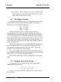
Trace Oxygen Analyzer
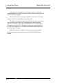
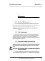
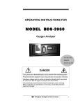
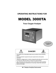
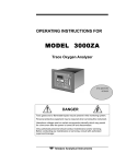
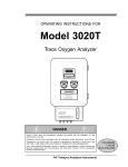
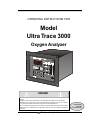
OPERATING INSTRUCTIONS FOR
Model
Ultra Trace 3000
Oxygen Analyzer
SET FL
OW
DANGER
HIGHLY TOXIC AND OR FLAMMABLE LIQUIDS OR GASES MAY BE PRESENT IN THIS MONITORING
SYSTEM.
PERSONAL PROTECTIVE EQUIPMENT MAY BE REQUIRED WHEN SERVICING THIS SYSTEM.
HAZARDOUS VOLTAGES EXIST ON CERTAIN COMPONENTS INTERNALLY WHICH MAY PERSIST
FOR A TIME EVEN AFTER THE POWER IS TURNED OFF AND DISCONNECTED.
ONLY AUTHORIZED PERSONNEL SHOULD CONDUCT MAINTENANCE AND/OR SERVICING. BEFORE
CONDUCTING ANY MAINTENANCE OR SERVICING CONSULT WITH AUTHORIZED SUPERVISOR/
MANAGER.
P/N M70946
12/10/99
ECO # 99-0483
Teledyne Analytical Instruments
i
Model Ultra Tace 3000
Copyright © 1999 Teledyne Analytical Instruments
All Rights Reserved. No part of this manual may be reproduced, transmitted, transcribed, stored in a retrieval system, or translated into any other language or computer
language in whole or in part, in any form or by any means, whether it be electronic,
mechanical, magnetic, optical, manual, or otherwise, without the prior written consent of
Teledyne Analytical Instruments, 16830 Chestnut Street, City of Industry, CA 91749-1580.
Warranty
This equipment is sold subject to the mutual agreement that it is warranted by us free
from defects of material and of construction, and that our liability shall be limited to
replacing or repairing at our factory (without charge, except for transportation), or at
customer plant at our option, any material or construction in which defects become
apparent within one year from the date of shipment, except in cases where quotations or
acknowledgements provide for a shorter period. Components manufactured by others bear
the warranty of their manufacturer. This warranty does not cover defects caused by wear,
accident, misuse, neglect or repairs other than those performed by Teledyne or an authorized service center. We assume no liability for direct or indirect damages of any kind and
the purchaser by the acceptance of the equipment will assume all liability for any damage
which may result from its use or misuse.
We reserve the right to employ any suitable material in the manufacture of our
apparatus, and to make any alterations in the dimensions, shape or weight of any parts, in
so far as such alterations do not adversely affect our warranty.
Important Notice
This instrument provides measurement readings to its user, and serves as a tool by
which valuable data can be gathered. The information provided by the instrument may
assist the user in eliminating potential hazards caused by his process; however, it is
essential that all personnel involved in the use of the instrument or its interface, with the
process being measured, be properly trained in the process itself, as well as all instrumentation related to it.
The safety of personnel is ultimately the responsibility of those who control process
conditions. While this instrument may be able to provide early warning of imminent danger,
it has no control over process conditions, and it can be misused. In particular, any alarm or
control systems installed must be tested and understood, both as to how they operate and
as to how they can be defeated. Any safeguards required such as locks, labels, or redundancy, must be provided by the user or specifically requested of Teledyne at the time the
order is placed.
Therefore, the purchaser must be aware of the hazardous process conditions. The
purchaser is responsible for the training of personnel, for providing hazard warning
methods and instrumentation per the appropriate standards, and for ensuring that hazard
warning devices and instrumentation are maintained and operated properly.
Teledyne Analytical Instruments, the manufacturer of this instrument, cannot
accept responsibility for conditions beyond its knowledge and control. No statement
expressed or implied by this document or any information disseminated by the manufacturer or its agents, is to be construed as a warranty of adequate safety control under the
user’s process conditions.
ii
Teledyne Analytical Instruments
Trace Oxygen Analyzer
Specific Model Information
The instrument for which this manual was supplied may incorporate one or
more options not supplied in the standard instrument. Commonly available
options are listed below, with check boxes. Any that are incorporated in the
instrument for which this manual is supplied are indicated by a check mark in the
box.
Instrument Serial Number: _______________________
Options Included in the Instrument with the Above Serial Number:
G Ultra Trace 3000-V: Instrument configured for Vacuum Service
G 19" Rack Mnt: The 19" Relay Rack Mount units are available with one
Ultra Trace 3000 series analyzers installed in a standard
19" panel and ready to mount in a standard rack.
Teledyne Analytical Instruments
iii
Model Ultra Tace 3000
Table of Contents
1 Introduction
1.1
1.2
1.3
1.4
1.5
1.6
Overview ........................................................................ 1-1
Typical Applications ....................................................... 1-1
Main Features of the Analyzer ....................................... 1-1
Model Designations ....................................................... 1-2
Front Panel (Operator Interface) ..................................... 1-3
Rear Panel (Equipment Interface) .................................. 1-5
2 Operational Theory
2.1 Introduction .................................................................... 2-1
2.2 Micro-Fuel Cell Sensor .................................................. 2-1
2.2.1 Principles of Operation ............................................ 2-1
2.2.2 Anatomy of a Micro-Fuel Cell .................................. 2-2
2.2.3 Electrochemical Reactions ...................................... 2-3
2.2.4 The Effect of Pressure.............................................. 2-4
2.2.5 Calibration Characteristics ...................................... 2-4
2.2.6 TEC Cooling System ............................................... 2-4
2.3 Sample System .............................................................. 2-5
2.4 Electronics and Signal Processing ................................ 2-8
3 Installation
3.1 Unpacking the Analyzer ................................................. 3-1
3.2 Mounting the Analyzer ................................................... 3-1
3.3 Rear Panel Connections ................................................ 3-3
3.3.1 Gas Connections ................................................... 3-3
3.3.2 Electrical Connections ........................................... 3-4
3.3.2.1 Primary Input Power ....................................... 3-4
3.3.2.2 50-pin Interface Connector ............................. 3-5
3.3.3 Remote Probe Connector ...................................... 3-8
3.4 Installing the Micro-Fuel Cell ......................................... 3-10
3.5 Testing the System ......................................................... 3-10
4 Operation
4.1 Introduction .................................................................... 4-1
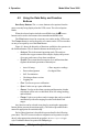
4.2 Using the Data Entry and Function Buttons ................... 4-2
4.3 The System Function ..................................................... 4-3
4.3.1 Tracking the O2 Readings during CAl & Alarm ....... 4-4
4.3.2 Setting up an Auto-Cal ........................................... 4-5
4.3.3 Password Protection .............................................. 4-6
4.3.3.1 Entering the Password ................................... 4-7
iv
Teledyne Analytical Instruments
Trace Oxygen Analyzer
4.3.3.2 Installing or Changing the Password ............. 4-8
4.3.4 Logout .................................................................... 4-9
4.3.5 System Self-Diagnostic Test .................................. 4-9
4.3.6 Version Screen ...................................................... 4-10
4.3.7 Filter Function ........................................................ 4-11
4.4 Calibration of the Analyzer ............................................. 4-11
4.4.1 Zero Cal ................................................................. 4-11
4.4.1.1 Auto Mode Zeroing ........................................ 4-12
4.4.1.2 Manual Mode Zeroing .................................... 4-13
4.4.1.3 Cell Failure .................................................... 4-13
4.4.2 Span Cal ................................................................ 4-14
4.4.2.1 Auto Mode Spanning ..................................... 4-14
4.4.2.2 Manual Mode Spanning................................. 4-15
4.4.3 Span Failure .......................................................... 4-16
4.5 Switching of Sample Streams ........................................ 4-17
4.5.1 Special notes on hydrogen gas stream .................. 4-17
4.6 The Alarms Function ...................................................... 4-17
4.7 The Range Function ...................................................... 4-20
4.7.1 Setting the Analog Output Ranges......................... 4-20
4.7.2 Fixed Range Analysis............................................ 4-21
4.8 The Analyze Function .................................................... 4-23
4.9 Signal Output ................................................................. 4-23
Maintenance
5.1 Routine Maintenance ..................................................... 5-1
5.2 Cell Replacement .......................................................... 5-1
5.2.1 Storing and Handling Replacement Cells ............... 5-1
5.2.2 When to Replace a Cell ........................................... 5-2
5.2.3 Removing the Micro-Fuel Cell ................................. 5-2
5.2.4 Installing a New Micro-Fuel Cell .............................. 5-4
5.2.5 Cell Warranty ........................................................... 5-4
5.3 Fuse Replacement......................................................... 5-5
5.4 System Self Diagnostic Test ........................................... 5-5
5.5 Major Internal Components ............................................ 5-6
5.6 Cleaning ........................................................................ 5-7
5.7 Troubleshooting ............................................................. 5-8
Appendix
A-1
A-2
A-3
A-4
A-5
Model Ultra Tace 3000 Specifications ............................ A-1
Recommended 2-Year Spare Parts List ......................... A-3
Drawing List ................................................................... A-4
19-Inch Relay Rack Panel Mount ................................... A-4
Application Notes on Pressures and Flow ..................... A-5
Teledyne Analytical Instruments
v
Model Ultra Tace 3000
DANGER
COMBUSTIBLE GAS USAGE WARNING
This is a general purpose instrument designed for use in a
nonhazardous area. It is the customer's responsibility to ensure
safety especially when combustible gases are being analyzed
since the potential of gas leaks always exist.
The customer should ensure that the principles of operation of
this equipment is well understood by the user. Misuse of this
product in any manner, tampering with its components, or unauthorized substitution of any component may adversely affect
the safety of this instrument.
Since the use of this instrument is beyond the control of
Teledyne, no responsibility by Teledyne, its affiliates, and agents
for damage or injury from misuse or neglect of this equipment is
implied or assumed.
vi
Teledyne Analytical Instruments
Ultra Trace Oxygen Analyzer
Introduction 1
Introduction
1.1
Overview
The Teledyne Analytical Instruments Model 3000 Ultra Trace Oxygen
Analyzer is a versatile microprocessor-based instrument for detecting oxygen
at the parts-per-billion (ppb) level in a variety of gases. This manual covers
the Model Ultra Trace 3000 General Purpose flush-panel and/or rack-mount
units only. These units are for indoor use in a nonhazardous environment.
1.2
Typical Applications
A few typical applications of the Model Ultra Trace 3000 are:
• Monitoring inert gas blanketing
• Air separation and liquefaction
• Chemical reaction monitoring
• Semiconductor manufacturing
• Petrochemical process control
• Quality assurance
• Gas analysis certification.
1.3
Main Features of the Analyzer
The Model 3000 Ultra Trace Oxygen Analyzer is sophisticated yet
simple to use. The main features of the analyzer include:
•
A 2-line alphanumeric vacuum fluorescent display (VFD) screen,
driven by microprocessor electronics, that continuously prompts
and informs the operator.
•
High resolution, accurate readings of oxygen content from low
ppm levels through 25%. Large, bright, meter readout.
•
Stainless steel cell block (wetted surfaces).
Teledyne Analytical Instruments
1-1
1 Introduction
Model Ultra Trace 3000
•
Advanced Micro-Fuel Cell, designed for trace analysis, has a 0250 ppb low range with less than a 100 ppb offset and six
months warranty and an expected lifetime of one year.
•
Versatile analysis over a wide range of applications.
•
Microprocessor based electronics: 8-bit CMOS microprocessor
with 32 kB RAM and 128 kB ROM.
•
Three user definable output ranges (from 0-250 ppb through 01000 ppm) allow best match to users process and equipment, plus
a fixed 1000 ppm over range.
•
Auto Ranging allows analyzer to automatically select the proper
preset range for a given measurement. Manual override allows
the user to lock onto a specific range of interest.
•
Two adjustable concentration alarms and a system failure alarm.
•
Extensive self-diagnostic testing, at startup and on demand, with
continuous power-supply monitoring.
•
Two way RFI protection.
•
RS-232 serial digital port for use with a computer or other digital
communication device.
•
Four analog outputs: two for measurement (0–1 V dc and
Isolated 4–20 mA dc) and two for range identification.
•
Convenient and versatile, steel, flush-panel or rack-mountable
case with slide-out electronics drawer.
1.4
Model Designations
Ultra Trace 3000:
Standard model for sample under pressure
Ultra Trace 3000-V: Instrument configured for Vacuum Service
1-2
Teledyne Analytical Instruments
Ultra Trace Oxygen Analyzer
1.5
Introduction 1
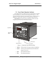
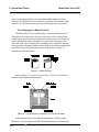
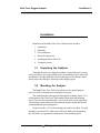
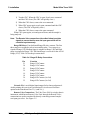
Front Panel (Operator Interface)
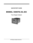
The standard Ultra Trace 3000 is housed in a rugged metal case with all
controls and displays accessible from the front panel. See Figure 1-1. The
front panel has thirteen buttons for operating the analyzer, a digital meter, an
alphanumeric display, and a window for viewing the sample flowmeter.
Function Keys: Six touch-sensitive membrane switches are used to
change the specific function performed by the analyzer:
Door Latch
Digital Meter
Alphanumeric
Display
SET FL
OW
Sample System
Flow Indicator
Standby Switch
Data Entry Buttons
Function Buttons
Figure 1-1: Model Ultra Trace 3000 Front Panel
•
Analyze
Perform analysis for oxygen content of a sample gas.
•
System
Perform system-related tasks (described in detail in
chapter 4, Operation.).
•
Span
Span calibrate the analyzer.
•
Zero
Zero calibrate the analyzer.
Teledyne Analytical Instruments
1-3
1 Introduction
Model Ultra Trace 3000
•
Alarms
Set the alarm setpoints and attributes.
•
Range
Set up the 3 user definable ranges for the instrument.
Data Entry Keys: Six touch-sensitive membrane switches are used to
input data to the instrument via the alphanumeric VFD display:
•
Left & Right Arrows
Select between functions currently
displayed on the VFD screen.
•
Up & Down Arrows
Increment or decrement values of
functions currently displayed.
•
Enter
•
Escape Moves VFD display back to the previous screen in a
series. If none remains, returns to the Analyze screen.
Moves VFD display on to the next screen in a series. If
none remains, returns to the Analyze screen.
Digital Meter Display: The meter display is a Light Emitting Diode
(LED) device that produces large, bright, 7-segment numbers that are legible
in any lighting. It produces a continuous readout from 0-999 ppb and then
switches to a continuous ppm readout from 0-9999.9 ppm. It is accurate
across all analysis ranges without the discontinuity inherent in analog range
switching.
Alphanumeric Interface Screen: The VFD screen is an easy-to-use
interface from operator to analyzer. It displays values, options, and messages
that give the operator immediate feedback.
NeedleValve: To adjust flow of gas sample
Flowmeter: Monitors the flow of gas past the sensor. Readout is 0.2 to
2.4 standard liters per minute (SLPM) of nitrogen
Standby Button: The Standby turns off the display and outputs,
but circuitry is still operating.
CAUTION: The power cable must be unplugged to fully
disconnect power from the instrument. When
chassis is exposed or when access door is open
and power cable is connected, use extra care to
avoid contact with live electrical circuits .
Access Door: For access to the Micro-Fuel Cell, the front panel
swings open when the latch in the upper right corner of the panel is pressed
1-4
Teledyne Analytical Instruments
Ultra Trace Oxygen Analyzer
Introduction 1
all the way in with a narrow gauge tool. Accessing the main circuit board
requires unfastening rear panel screws and sliding the unit out of the case.
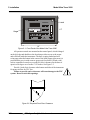
1.6
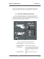
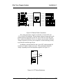
Rear Panel (Equipment Interface)
The rear panel, shown in Figure 1-2, contains the gas and electrical
connectors for external inlets and outlets. Some of those depicted are optional and may not appear on your instrument. The connectors are described
briefly here and in detail in chapter 3 Installation.
T el e d y n e A n a ly tic a l I n str u m e n ts
Figure 1-2: Model Ultra Trace 3000 Rear Panel
•
Power Connection
Universal AC power source.
•
Gas Inlet and Outlet
One inlet and one exhaust out.
•
Analog Outputs
0–1 V dc oxygen concentration plus 0-1
V dc range ID, and isolated 4–20 mA dc
oxygen concentration plus 4-20 mA dc
range ID.
•
Alarm Connections
2 concentration alarms and 1 system
alarm.
Teledyne Analytical Instruments
1-5
1 Introduction
Model Ultra Trace 3000
•
RS-232 Port
Serial digital concentration signal output
and control input.
•
Remote Probe
Used in the Ultra Trace3000 for
controlling external solenoid valves
only.
•
Remote Span/Zero
Digital inputs allow external control of
analyzer calibration.
•
Calibration Contact
To notify external equipment that
instrument is being calibrated and
readings are not monitoring sample.
•
Range ID Contacts
Four separate, dedicated, range relay
contacts. Low, Medium, High, Cal.
•
Network I/O
Serial digital communications for local
network access. For future expansion.
Not implemented at this printing.
Note: If you require highly accurate Auto-Cal timing, use external
Auto-Cal control where possible. The internal clock in the
Model Ultra Trace 3000 is accurate to 2-3 %. Accordingly,
internally scheduled calibrations can vary 2-3 % per day.
1-6
Teledyne Analytical Instruments
Ultra Trace Oxygen Analyzer
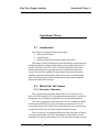
Operational Theory 2
Operational Theory
2.1
Introduction
The analyzer is composed of three subsystems:
1. Micro-fuel Cell Sensor
2. Sample System
3. Electronic Signal Processing, Display and Control
The sample system is designed to accept the sample gas and transport it
through the analyzer without contaminating or altering the sample prior to
analysis. The Micro-fuel Cell is an electrochemical galvanic device that
translates the amount of oxygen present in the sample into an electrical
current. The electronic signal processing, display and control subsystem
simplifies operation of the analyzer and accurately processes the sampled
data. The microprocessor controls all signal processing, input/output and
display functions for the analyzer.
2.2
Micro-Fuel Cell Sensor
2.2.1 Principles of Operation
The oxygen sensor used in the Model Ultra Trace 3000 series is a
Micro-fuel Cell, Model B-2CXL designed and manufactured by Analytical
Instruments. It is a sealed plastic disposable electrochemical transducer.
The active components of the Micro-fuel Cell are a cathode, an anode,
and the aqueous KOH electrolyte in which they are immersed. The cell
converts the energy from a chemical reaction into an electrical current in an
external electrical circuit. Its action is similar to that of a battery.
There is, however, an important difference in the operation of a battery
as compared to the Micro-fuel Cell: In the battery, all reactants are stored
within the cell, whereas in the Micro-fuel Cell, one of the reactants (oxygen)
Teledyne Analytical Instruments
2-1
2 Operational Theory
Model Ultra Trace 3000
comes from outside the device as a constituent of the sample gas being
analyzed. The Micro-Fuel Cell is therefore a hybrid between a battery and a
true fuel cell. (All of the reactants are stored externally in a true fuel cell.)
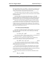
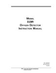
2.2.2 Anatomy of a Micro-Fuel Cell
The Micro-Fuel Cell is a cylinder only 1¼ inches in diameter and 1¼
inches thick. It is made of an extremely inert plastic, which can be placed
confidently in practically any environment or sample stream. It is effectively
sealed, although one end is permeable to oxygen in the sample gas. The
other end of the cell is a contact plate consisting of two concentric foil rings.
The rings mate with spring-loaded contacts in the sensor block assembly and
provide the electrical connection to the rest of the analyzer. Figure 2-1
illustrates the external features.
Figure 2-1: Micro-fuel Cell
Refer to Figure 2-2, Cross Section of a Micro-Fuel Cell, which illustrates the following internal description.
Figure 2-2. Cross Section of a Micro-Fuel Cell (not to scale)
At the top end of the cell is a diffusion membrane of Teflon, whose
thickness is very accurately controlled. Beneath the diffusion membrane lies
2-2
Teledyne Analytical Instruments
Ultra Trace Oxygen Analyzer
Operational Theory 2
the oxygen sensing element—the cathode—with a surface area almost 4 cm2.
The cathode has many perforations to ensure sufficient wetting of the upper
surface with electrolyte, and it is plated with an inert metal.
The anode structure is below the cathode. It is made of lead and has a
proprietary design which is meant to maximize the amount of metal available
for chemical reaction.
At the rear of the cell, just below the anode structure, is a flexible
membrane designed to accommodate the internal volume changes that occur
throughout the life of the cell. This flexibility assures that the sensing membrane remains in its proper position, keeping the electrical output constant.
The entire space between the diffusion membrane, above the cathode,
and the flexible rear membrane, beneath the anode, is filled with electrolyte.
Cathode and anode are submerged in this common pool. They each have a
conductor connecting them to one of the external contact rings on the contact
plate, which is on the bottom of the cell.
2.2.3 Electrochemical Reactions
The sample gas diffuses through the Teflon membrane. Any oxygen in
the sample gas is reduced on the surface of the cathode by the following
HALF REACTION:
O2 + 2H2O + 4e– → 4OH–
(cathode)
(Four electrons combine with one oxygen molecule—in the presence of
water from the electrolyte—to produce four hydroxyl ions.)
When the oxygen is reduced at the cathode, lead is simultaneously
oxidized at the anode by the following HALF REACTION:
Pb + 2OH– → Pb+2 + H2O + 2e–
(anode)
(Two electrons are transferred for each atom of lead that is oxidized.
Therefore it takes two of the above anode reactions to balance one cathode
reaction and transfer four electrons.)
The electrons released at the surface of the anode flow to the cathode
surface when an external electrical path is provided. The current is proportional to the amount of oxygen reaching the cathode. It is measured and used
to determine the oxygen concentration in the gas mixture.
The overall reaction for the fuel cell is the SUM of the half reactions
above, or:
2Pb + O2 → 2PbO
Teledyne Analytical Instruments
2-3
2 Operational Theory
Model Ultra Trace 3000
(These reactions are specific to oxygen as long as no gaseous components
capable of oxidizing lead—such as iodine, bromine, chlorine and fluorine—are
present in the sample.)
In the absence of oxygen, no current is generated.
2.2.4 The Effect of Pressure
In order to state the amount of oxygen present in the sample in ppb or
parts-per-million of the gas mixture, it is necessary that the sample diffuse into
the cell under constant pressure.
If the total pressure increases, the rate that oxygen reaches the cathode
through the diffusing membrane will also increase. The electron transfer, and
therefore the external current, will increase, even though the oxygen concentration of the sample has not changed. It is therefore important that the sample
pressure at the fuel cell (usually vent pressure) remain relatively constant
between calibrations.
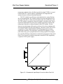
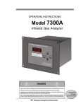
2.2.5 Calibration Characteristics
Given that the total pressure of the sample gas on the surface of the
Micro-Fuel Cell input is constant, a convenient characteristic of the cell is that
the current produced in an external circuit is directly proportional to the rate at
which oxygen molecules reach the cathode, and this rate is directly proportional to the concentration of oxygen in the gaseous mixture. In other words it
has a linear characteristic curve, as shown in Figure 2-3. Measuring circuits do
not have to compensate for nonlinearities.
In addition, since there is zero output in the absence of oxygen, the
characteristic curve has close to an absolute zero (less than ± 0.1 ppm oxygen).
Depending upon the application, zeroing may still be used to compensate for
the combined zero offsets of the cell and the electronics.
2.2.6 TEC Cooling System
Ultra Trace 3000 analyzers include an advance Thermal Electric
Cooler (TEC) system. This system enhances the performance of the Micro-fuel
Cell by cooling it and regulating its operating temperature. The TEC system
includes a TEC module, a temperature control PCB, a separate power supply,
a thermistor, and a special insulated cellblock. The system is used to regulate
the cell temperature at 11 degrees C. Operating the Micro-fuel Cell at a low
2-4
Teledyne Analytical Instruments
Ultra Trace Oxygen Analyzer
Operational Theory 2
temperature minimizes the cell offset (typically less than 75 PPB). A second
benefit of the TEC system is that by regulating the cell temperature the
analyzer becomes tolerant of thermal transients.
The TEC module is a solid-state semiconductor heat – pump. Passing
DC current through the TEC module produces heat flow though the device.
One side of the device will become hot and the other side will become cold.
The TEC module is attached to a heat-sink which is cooled by a fan. This is
required to maintain the hot side at an acceptable temperature. The hot side
temperature limits the overall performance of the TEC module. The fan
draws air into the bottom of the analyzer, this air is forced over the heat sink
and exits through the left side of the analyzer. The power for the TEC device
is supplied by a Pulse Width Modulated (PWM) proportional switching
temperature controller. The temperature controller PCB supplies a 12 volt
pulse whose duty cycle is proportional to the cooling required. The temperature controller PCB uses a thermistor to monitor the temperature of the of cell
block. Power for the fan, and the temperature controller PCB is supplied by
a separate 12VDC power supply.
Figure 2-3. Characteristic Input/Output Curve for a Micro-Fuel Cell
Teledyne Analytical Instruments
2-5
2 Operational Theory
2.3
Model Ultra Trace 3000
Sample System
The sample system delivers gases to the Micro-Fuel Cell sensor from
the analyzer rear panel inlet. Depending on the mode of operation either
sample or calibration gas is delivered.
The Model Ultra Trace 3000 sample system is designed and fabricated
to ensure that the oxygen concentration of the gas is not altered as it travels
through the sample system.
The sample system for the standard instrument incorporates 1/4" VCR
for sample inlet and outlet tube connections at the rear panel. The sample or
calibration gas that flows through the system is monitored by a flowmeter
downstream from the cell. Figure 2-4 shows the piping layout and flow
diagram for the standard model.
Figure 2-4: Piping Layout
2-6
Teledyne Analytical Instruments
Ultra Trace Oxygen Analyzer
Operational Theory 2
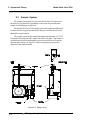
Figure 2-5: Flow Diagram-Sample Under Pressure
-Standard Model Ultra Trace 3000
-Do not exceed 10" Hg Vacuum-
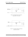
Figure 2-5-1: Flow Diagram-Sample at Zero Pressure
-Model Ultra Trace 3000-V
Teledyne Analytical Instruments
2-7
2 Operational Theory
Model Ultra Trace 3000
Figure 2-5 is the flow diagram for the sampling system. In the standard
instrument, calibration gases can be connected directly to the Sample In port
by teeing to the port with appropriate valves.
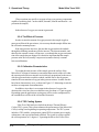
2.4
Electronics and Signal Processing
The Model Ultra Trace 3000 Oxygen Analyzer uses an 8031 microcontroller with 32 kB of RAM and 128 kB of ROM to control all signal processing, input/output, and display functions for the analyzer. System power
is supplied from a universal power supply module designed to be compatible
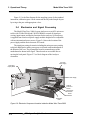
with any international power source. Figure 2-6 shows the location of the
power supply and the main electronic PC boards.
The signal processing electronics including the microprocessor, analog
to digital, and digital to analog converters are located on the motherboard at
the bottom of the case. The preamplifier board is mounted on top of the
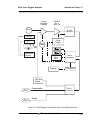
motherboard as shown in the figure. These boards are accessible after removing the back panel. Figure 2-7 is a block diagram of the Analyzer
electronics.
Universal
Power Supply
Front Panel
Display Board
TEC Power Supply
Slide-out
Electronics
Drawer
Temperature
Controller
Board
Motherboard
Preamplifier
PCB
Figure 2-6: Electronic Component Location Inside the Model Ultra Trace 3000
2-8
Teledyne Analytical Instruments
Ultra Trace Oxygen Analyzer
Current
to Voltage
Amplifier
Operational Theory 2
Second
Stage
Amplifier
Sensor
A to D
Converter
Thermistor
TEC
Auto
Range
Power
Supply
HEAT
SINK
FAN
Temperature
Controller
System
Failure
Alarm
Displays
MicroProcessor
Processing
Self Test
Signal
0-1 V
4-20 mA
0-1 V
4-20 mA
Concentration
D to A
Converter
Range
Figure 2-7: Block Diagram of the Model Ultra Trace 3000 Electronics
Teledyne Analytical Instruments
2-9
2 Operational Theory
Model Ultra Trace 3000
In the presence of oxygen the cell generates a current. A current to
voltage amplifier converts this current to a voltage, which is further amplified
in the second stage amplifier.
The output from the second stage amplifier is sent to an 18 bit analog
to digital converter controlled by the microprocessor.
The digital concentration signal along with input from the control panel
is processed by the microprocessor, and appropriate control signals are
directed to the display, alarms and communications port. The same digital
information is also sent to a 12 bit digital to analog converter that produces
the 4-20 mA dc and the 0-1 V dc analog concentration signal outputs, and
the analog range ID outputs.
Signals from the power supply are also monitored, and through the
microprocessor, the system failure alarm is activated if a malfunction is
detected.
2-10
Teledyne Analytical Instruments
Ultra Trace Oxygen Analyzer
Installation 3
Installation
Installation of the Model Ultra Trace 3000 Analyzer includes:
1.
2.
3.
4.
5.
6.
Unpacking
Mounting
Gas connections
Electrical connections
Installing the Micro-Fuel Cell
Testing the system.
3.1
Unpacking the Analyzer
Although the analyzer is shipped complete, certain of the parts, such as
fuses and sensors, are wrapped separately to be installed on site as part of the
installation. Carefully unpack the analyzer and inspect it for damage. Immediately report any damage or shortages to the shipping agent.
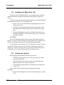
3.2
Mounting the Analyzer
The Model Ultra Trace 3000 is for indoor use in a general purpose
area. It is NOT for hazardous environments of any type.
The standard model is designed for flush panel mounting. Figure 3-1 is
an illustration of the Ultra Trace 3000 standard front panel and mounting
bezel. There are four mounting holes—one in each corner of the rigid frame.
The drawings section in the rear of this manual contains outline dimensions
and mounting hole spacing diagrams.
On special order, a 19" rack-mounting panel can be provided. For rack
mounting, one Ultra Trace 3000 series analyzer is flush-panel mounted on
the rack panel. See Appendix for dimensions of the mounting panel.
Teledyne Analytical Instruments
3-1
3 Installation
Model Ultra Trace 3000
Latch
ULTRA TRACE 3000
ULTRA TRACE ANALYZER
Analyze
System
Span
Zero
Alarms
Range
2.0
1.0
Hinge
Enter
Escape
Set Flow
6.7”
Standby
10”
Figure 3-1: Front Panel of the Model Ultra Trace 3000
All operator controls are mounted on the control panel, which is hinged
on the left edge and doubles as the door that provides access to the sensor
and cell block inside the instrument. The door is spring loaded and will
swing open when the button in the center of the latch (upper right corner) is
pressed all the way in with a narrow gauge tool (less than 0.18 inch wide),
such as a small hex wrench or screwdriver Allow clearance for the door to
open in a 90-degree arc of radius 7.125 inches. See Figure 3-2.
Provide 1 inch of air clearance at the bottom and sides of the instrument
for proper air flow for TEC fun.
Failure to provide such a clearance will cause damage to the TEC
system. Do not restrict this openings.
Figure 3-2: Required Front Door Clearance
3-2
Teledyne Analytical Instruments
Ultra Trace Oxygen Analyzer
3.3
Installation 3
Rear Panel Connections
Figure 3-3 shows the Model Ultra Trace 3000 rear panel. There are
ports for gas inlet and outlet, power, communication, and both digital and
analog concentration output.
Te le d y n e A n aly tic a l In s tru m e n ts
Figure 3-3: Rear Panel of the Model Ultra Trace 3000
3.3.1 Gas Connections
The unit is manufactured with 1/4 inch VCR fittings. For a safe connection:
SAMPLE IN: In the standard model, gas connections are made at the
SAMPLE IN and EXHAUST OUT connections. Calibration gases must be
Tee'd into the Sample inlet with appropriate valves. A VCR fitting is provided for the inlet connection.
The inlet gas pressure should be reasonably regulated. Pressures between 1 and 50 psig are acceptable as long as the pressure, once established,
will keep the front panel flowmeter reading in an acceptable range (0.5 to 2.0
SLPM). For non-pressurized sample or very low pressure, (less than 1 psig)
vacuum service plumbing is recommended. (See next section: Vacuum
Service).
Teledyne Analytical Instruments
3-3
3 Installation
Model Ultra Trace 3000
If greater sample flow is required for improved response time, install a
bypass in the sampling system upstream of the analyzer input.
VACUUM SERVICE: If the sample pressure is at atmospheric or
very low pressure, the instrument must be ordered with the vacuum service
option. This will ensure that the flow control valve is located on the exhaust
side of the Micro-Fuel Cell.
EXHAUST OUT: Exhaust connections must be consistent with the
hazard level of the constituent gases. Check Local, State, and Federal laws,
and ensure that the exhaust stream vents to an appropriately controlled area,
if required.
3.3.2 Electrical Connections
For safe connections, no uninsulated wiring should be able to come in
contact with fingers, tools or clothing during normal operation.
CAUTION: Use Shielded Cables. Also, use plugs that provide
excellent EMI/RFI protection. The plug case must be
connected to the cable shield, and it must be tightly
fastened to the analyzer with its fastening screws.
Ultimately, it is the installer who ensures that the
connections provide adequate EMI/RFI sielding.
3.3.2.1
Primary Input Power
The power cord receptacle and fuse block are located in the same
assembly. Insert the power cord into the power cord receptacle.
CAUTION: Power is applied to the instrument's circuitry as
long as the instrument is connected to the power
source. The red
switch on the front panel is for
switching power on or off to the displays and outputs only.
The universal power supply requires a 85–250 V ac, 47-63 Hz power
source.
Fuse Installation: The fuse block, at the right of the power cord
receptacle, accepts US or European size fuses. A jumper replaces the fuse in
whichever fuse receptacle is not used. Fuses are not installed at the factory.
Be sure to install the proper fuse as part of installation. (See Fuse Replacement in chapter 5, maintenance.)
3-4
Teledyne Analytical Instruments
Ultra Trace Oxygen Analyzer
3.3.2.2
Installation 3
50-Pin Equipment Interface Connector
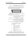
Figure 3-4 shows the pin layout of the Equipment Interface connector.
The arrangement is shown as seen when the viewer faces the rear panel of
the analyzer. The pin numbers for each input/output function are given
where each function is described in the paragraphs below.
Figure 3-4: Equipment Interface Connector Pin Arrangement
Analog Outputs: There are four DC output signal pins—two pins per
output. For polarity, see Table 3-1. The outputs are:
0–1 V dc % of Range: Voltage rises linearly with increasing oxygen, from
0 V at 0 ppm to 1 V at full scale ppm. (Full scale =
100% of programmable range.)
0–1 V dc Range ID:
0.25 V = Low Range, 0.5 V = Medium Range,
0.75 V = High Range, 1 V = Air Cal Range.
4–20 mA dc % Range: Current increases linearly with increasing oxygen,
from 4 mA at 0 ppm to 20 mA at full scale ppm.
(Full scale = 100% of programmable range.)
4–20 mA dc Range ID: 8 mA = Low Range, 12 mA = Medium Range, 16
mA = High Range, 20 mA = Air Cal Range.
Table 3-1: Analog Output Connections
Pin
Function
3
+ Range ID, 4-20 mA, floating
4
– Range ID, 4-20 mA, floating
5
+ % Range, 4-20 mA, floating
6
– % Range, 4-20 mA, floating
8
+ Range ID, 0-1 V dc
23
– Range ID, 0-1 V dc, negative ground
24
+ % Range, 0-1 V dc
7
– % Range, 0-1 V dc, negative ground
Alarm Relays: The nine alarm-circuit connector pins connect to the
internal alarm relay contacts. Each set of three pins provides one set of Form
C relay contacts. Each relay has both normally open and normally closed
Teledyne Analytical Instruments
3-5
3 Installation
Model Ultra Trace 3000
contact connections. The contact connections are shown in Table 3-2. They
are capable of switching up to 3 amperes at 250 V ac into a resistive load.
The connectors are:
Threshold Alarm 1:
• Can be configured as high (actuates when concentration is above threshold), or low (actuates when
concentration is below threshold).
• Can be configured as failsafe or nonfailsafe.
• Can be configured as latching or nonlatching.
• Can be configured out (defeated).
Threshold Alarm 2:
• Can be configured as high (actuates when concentration is above threshold), or low (actuates when
concentration is below threshold).
• Can be configured as failsafe or nonfailsafe.
• Can be configured as latching or nonlatching.
• Can be configured out (defeated).
System Alarm:
Actuates when DC power supplied to circuits is
unacceptable in one or more parameters. Permanently
configured as failsafe and latching. Cannot be defeated. Actuates if self test fails.
(Reset by pressing
button to remove power. Then
press
again and any other button EXCEPT
System to resume.
Further detail can be found in chapter 4, section 4-5.
Table 3-2: Alarm Relay Contact Pins
Pin
45
28
46
42
44
43
36
20
37
Contact
Threshold Alarm 1, normally closed contact
Threshold Alarm 1, moving contact
Threshold Alarm 1, normally open contact
Threshold Alarm 2, normally closed contact
Threshold Alarm 2, moving contact
Threshold Alarm 2, normally open contact
System Alarm, normally closed contact
System Alarm, moving contact
System Alarm, normally open contact
Digital Remote Cal Inputs: Accept 0 V (off) or 24 V dc (on) inputs
for remote control of calibration. (See Remote Calibration Protocol below.)
See Table 3-3 for pin connections.
3-6
Teledyne Analytical Instruments
Ultra Trace Oxygen Analyzer
Installation 3
Zero:
Floating input. 5 to 24 V input across the + and – pins puts
the analyzer into the Zero mode. Either side may be
grounded at the source of the signal. 0 to 1 volt across the
terminals allows Zero mode to terminate when done. A
synchronous signal must open and close the external zero
valve appropriately. See Remote Probe Connector. (The –C
option internal valves operate automatically.)
Span:
Floating input. 5 to 24 V input across the + and – pins puts
the analyzer into the Span mode. Either side may be
grounded at the source of the signal. 0 to 1 volt across the
terminals allows Span mode to terminate when done. A
synchronous signal must open and close external span valve
appropriately. See Figure 3-5 Remote Probe Connector. (The
–C option internal valves operate automatically.)
Cal Contact: This relay contact is closed while analyzer is spanning
and/or zeroing. (See Remote Calibration Protocol below.)
Table 3-3: Remote Calibration Connections
Pin
9
11
10
12
40
41
Function
+ Remote Zero
– Remote Zero
+ Remote Span
– Remote Span
Cal Contact
Cal Contact
Remote Calibration Protocol: To properly time the Digital Remote
Cal Inputs to the Model Ultra Trace 3000 Analyzer, the customer's controller
must monitor the Cal Relay Contact.
When the contact is OPEN, the analyzer is analyzing, the Remote Cal
Inputs are being polled, and a zero or span command can be sent.
When the contact is CLOSED, the analyzer is already calibrating. It
will ignore your request to calibrate, and it will not remember that request.
Once a zero or span command is sent, and acknowledged (contact
closes), release it. If the command is continued until after the zero or span is
complete, the calibration will repeat and the Cal Relay Contact (CRC) will
close again.
For example:
Teledyne Analytical Instruments
3-7
3 Installation
Model Ultra Trace 3000
1) Test the CRC. When the CRC is open, Send a zero command
until the CRC closes (The CRC will quickly close.)
2) When the CRC closes, remove the zero command.
3) When CRC opens again, send a span command until the CRC
closes. (The CRC will quickly close.)
4) When the CRC closes, remove the span command.
When CRC opens again, zero and span are done, and the sample is
being analyzed.
Note: The Remote Valve connections (described below) provides
signals to ensure that the zero and span gas valves will be
controlled synchronously.
Range ID Relays: Four dedicated Range ID relay contacts. The first
three ranges are assigned to relays in ascending order—Low range is assigned to Range 1 ID, Medium range is assigned to Range 2 ID, and High
range is assigned to Range 3 ID. The fourth range is reserved for the Air Cal
Range (25%). Table 3-4 lists the pin connections.
Table 3-4: Range ID Relay Connections
Pin
21
38
22
39
19
18
34
35
Function
Range 1 ID Contact
Range 1 ID Contact
Range 2 ID Contact
Range 2 ID Contact
Range 3 ID Contact
Range 3 ID Contact
Range 4 ID Contact (Air Cal)
Range 4 ID Contact (Air Cal)
Network I/O: A serial digital input/output for local network protocol.
At this printing, this port is not yet functional. It is to be used for future
options to the instrument. Pins 13 (+) and 29 (–).
Remote Valve Connections: The Ultra Trace 3000 is a single-chassis
instrument, which has no Remote Valve Unit. Instead, the Remote Valve
connections are used as a method for directly controlling external sample/
zero/span gas valves. See Figure 3-5.
3-8
Teledyne Analytical Instruments
Ultra Trace Oxygen Analyzer
Installation 3
Figure 3-5: Remote Probe Connections
The voltage from these outputs is nominally 0 V for the OFF and
15 V dc for the ON conditions. The maximum combined current that can be
pulled from these output lines is 100 mA. (If two lines are ON at the same
time, each must be limited to 50 mA, etc.) If more current and/or a different
voltage is required, use a relay, power amplifier, or other matching circuitry
to provide the actual driving current.
In addition, each individual line has a series FET with a nominal ON
resistance of 5 ohms (9 ohms worst case). This can limit the obtainable
voltage, depending on the load impedance applied. See Figure 3-6.
Figure 3-6: FET Series Resistance
Teledyne Analytical Instruments
3-9
3 Installation
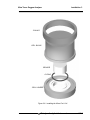
3.4
Model Ultra Trace 3000
Installing the Micro-Fuel Cell
The Micro-Fuel Cell, Model B-2CXL is not installed in the cell block
when the instrument is shipped. Install it before the analyzer is placed in
service.
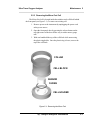
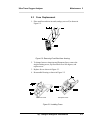
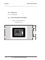
The Micro-Fuel cell is located inside the stainless steel cell block behind
the front panel (see Figure 3-8). To install the cell:
1. Remove power to the instrument by unplugging the power cord
at the power source.
2. Open the front panel door by pressing the release button on the
top right corner of the door all the way in with a narrow gauge
tool.
3. With one hand hold the top of the cell block while unscrewing
the plastic ring holder. Once the plastic ring is loose, remove the
top of the cell block.
CAUTION:
The cell is shipped separately inside two bags filled with oxygen-free
inert gas. Extreme care must be taken to ensure that the cell is exposed to air
for the very minimum amount of time, including during installation.
As an example, an air exposure of 3 to 5 minutes may require 24 hours
or longer before the cell recovers to less than 0.5 ppm on an oxygen free
sample gas. On the other hand, if the air exposure is limited to less than 10
seconds, the recovery time will be reduced to two hours, or less.
3.5
Testing the System
Before plugging the instrument into the power source:
•
Check the integrity and accuracy of the gas connections. Make
sure there are no leaks.
• Check the integrity and accuracy of the electrical connections.
Make sure there are no exposed conductors
• Check that inlet sample pressure is within the accepted range (se
section 3.3.1).
Power up the system, and test it by performing the following
operations:
1. Repeat the Self-Diagnostic Test as described in chapter 4, section
4.3.5.
3-10
Teledyne Analytical Instruments
Ultra Trace Oxygen Analyzer
Installation 3
COLLAR
CELL BLOCK
SENSOR
O-RING
CELL HOLDER
Figure 3-8: Installing the Micro-Fuel Cell
Teledyne Analytical Instruments
3-11
3 Installation
Model Ultra Trace 3000
IMPORTANT: `
3-12
In the event of loss of flow through the analyzer, if
the vent is vented to a location of high oxygen
content, oxygen will back diffuse through the vent
line and in most cases quickly saturate the cell with
oxygen which can then require a quite long purge
down time for the sensor when then exposed to low
oxygen concentrations. In the event that flow is to
be interrupted into the analyzer, it is suggested that
the user do one of the following:
1.
Bag the sensor in nitrogen during this time
2.
Install a shut off valve on the vent port of the analyzer or somewhere within the users sample system.
Teledyne Analytical Instruments
Ultra Trace Oxygen Analyzer
Operation 4
Operation
4.1
Introduction
Once the analyzer has been installed, it can be configured for your
application. To do this you will:
•
•
•
•
Set system parameters:
• Establish a security password, if desired, requiring Operator
to log in.
• Establish and start an automatic calibration cycle, if desired.
Calibrate the instrument.
Define the three user selectable analysis ranges, then choose
autoranging or select a fixed range of analysis, as required.
Set alarm setpoints, and modes of alarm operation (latching,
failsafe, etc).
Before you configure your Ultra Trace 3000, these default values are in
effect:
Ranges: LO = 250ppb ppm, MED = 1 ppm, HI = 10 ppm.
Auto Ranging: ON
Alarm Relays: Defeated, Alarm 1 at10.000 ppm, Alarm 2 at 1.000
ppm HI, Not failsafe, Not latching.
Zero: Auto, every 0 days at 0 hours.
Span: Auto, at 008.00 ppm, every 0 days at 0 hours.
If you choose not to use password protection, the default password is
automatically displayed on the password screen when you start up, and you
simply press Enter for access to all functions of the analyzer.
Teledyne Analytical Instruments
4-1
4 Operation
Model Ultra Trace 3000
4.2
Using the Data Entry and Function
Buttons
Data Entry Buttons: The < > arrow buttons select options from the
menu currently being displayed on the VFD screen. The selected option
blinks.
When the selected option includes a modifiable item, the ∆ ∇ arrow
buttons can be used to increment or decrement that modifiable item.
The Enter button is used to accept any new entries on the VFD screen.
The Escape button is used to abort any new entries on the VFD screen that
are not yet accepted by use of the Enter button.
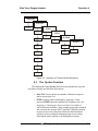
Figure 4-1 shows the hierarchy of functions available to the operator via
the function buttons. The six function buttons on the analyzer are:
• Analyze. This is the normal operating mode. The analyzer
monitors the oxygen content of the sample, displays the percent
of oxygen, and warns of any alarm conditions.
• System. The system function consists of six subfunctions that
regulate the internal operations of the analyzer:
•
•
•
•
•
•
•
•
•
Auto-Cal setup
Password assignment
Self -Test initiation
Checking software version
Logging out.
• Show negative readings
• Set digital filter
Zero. Used to set up a zero calibration.
Span. Used to set up a span calibration.
Alarms. Used to set the alarm setpoints and determine whether
each alarm will be active or defeated, HI or LO acting, latching,
and/or failsafe.
Range. Used to set up three analysis ranges that can be switched
automatically with auto-ranging or used as individual fixed
ranges.
Any function can be selected at any time by pressing the appropriate
button (unless password restrictions apply). The order as presented in this
manual is appropriate for an initial setup.
Each of these functions is described in greater detail in the following
procedures. The VFD screen text that accompanies each operation is reproduced, at the appropriate point in the procedure, in a Monospaced type
style. Pushbutton names are printed in Oblique type.
4-2
Teledyne Analytical Instruments
Ultra Trace Oxygen Analyzer
Operation 4
ANALYZE
SYSTEM
Perform Oxygen
Analysis of
the Sample
SPAN
TRAK/HLD
ZERO
Set Instrument
Span
Perform
Self-Diagnostic
Test
Initiate
Automatic
Calibration
ALARMS
Set Instrument
Zero
RANGSet Alarm
Setpoints
Set Password
Confrigure Mode
of Alarm
Operation
Define Analysis
Ranges
Logout
Neg
Filter
Figure 4-1: Hierarchy of Functions and Subfunctions
4.3
The System Function
The subfuctions of the System function are described below. Specific
procedures for their use follow the descriptions:
•
•
Auto-Cal: Used to define an automatic calibration sequence
and/or start an Auto-Cal.
PSWD: Security can be established by choosing a 5 digit
password (PSWD) from the standard ASCII character set. (See
Installing or Changing the Password, below, for a table of
ASCII characters available.) Once a unique password is assigned
and activated, the operator MUST enter the UNIQUE password
to gain access to set-up functions which alter the instrument's
operation, such as setting the instrument span or zero setting,
adjusting the alarm setpoints, or defining analysis ranges.
Teledyne Analytical Instruments
4-3
4 Operation
•
•
•
•
•
•
•
Model Ultra Trace 3000
After a password is assigned, the operator must log out to
activate it. Until then, anyone can continue to operate the
instrument without entering the new password.
Only one password can be defined. Before a unique password
is assigned, the system assigns TETAI by default. This allows
access to anyone. After a unique password is assigned, to defeat
the security, the password must be changed back to TETAI.
Logout: Logging out prevents unauthorized tampering with
analyzer settings.
More: Select and enter More to get a new screen with
additional subfunctions listed.
SelfTest: The instrument performs a self-diagnostic test to
check the integrity of the power supply, output boards and
amplifiers.
Version: Displays Manufacturer, Model, and Software Version
of instrument.
Neg: The operator selects whether display can show negative
oxygen readings or not.
TRAK/HLD: The operator sets whether the instrument analog
outputs track the concentration change during calibration and sets
a time delay for the concentration alarms after calibration.
Filter: This is to set the response time of the digital filter in the
LO range.
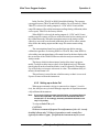
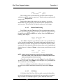
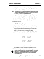
4.3.1 Tracking the Oxygen Readings during Calibration
and Alarm delay
The user has the option of setting the preferenc as to whether the analog
outputs track the display readings during calibration or not. To set the preference, press the System key once and the first System menu will appear in the
VFD display:
TRAK/HLD Auto-Cal
PSWD Logout More
TRAK/HLD should be blinking. To enter this system menu press the
Enter key once:
Output Sttng: TRACK
Alarm Dly: 10 min
Or
Output Sttng: HOLD
Alarm Dly: 10 min
4-4
Teledyne Analytical Instruments
Ultra Trace Oxygen Analyzer
Operation 4
In the first line, TRACK or HOLD should be blinking. The operator
can toggle between TRACK and HOLD with the Up or Down keys. When
TRACK is selected, the analog outputs (0-1 VDC and 4-20 ma) and the
range ID contacts will track the instrument readings during calibration (either
zero or span). TRACK is the factory default.
When HOLD is selected, the analog outputs (0-1 VDC and 4-20 ma)
and the range ID contacts will freeze on their last state before entering one of
the calibration modes. When the instrument returns to the Analyze mode,
either by a successful or an aborted calibration, there will be a three-minute
delay before the analog outputs and the range ID contacts start tracking
again.
The concentration alarms freeze on their last state before entering
calibration regardless of selecting HOLD or TRACK. But, when HOLD is
selected the concentration alarms will remain frozen for the time displayed in
the second line of the TRAK/HLD menu after the analyzer returns to the
Analyze mode.
The factory default is three minutes, but the delay time is programmable. To adjust to delay time use the Left or Right arrow keys. When the
time displayed on the second line blinks, it can be adjusted by Pressing the
Up or Down keys to increase or decrease its value. The minimum delay is 1
minute, the maximum is 30.
This preference is stored in non-volatile memory so that it is recovered
if power is removed from the instrument.
4.3.2 Setting up an Auto-Cal
When proper automatic valving is connected (see chapter 3, installation), the Analyzer can cycle itself through a sequence of steps that automatically calibrates the instrument.
Note:
If you require highly accurate Auto-Cal timing, use external Auto-Cal
control where possible. The internal clock in the Model 3000-XL is
acurate to 2-3 %. Accordingly, internally scheduled calibrations can
vary 2-3 % per day.
To setup an AutoCal cycle:
CAUTION:
We do not recommend frequent Zero adjustments of the cell. A newly
installed cell may take 7-10 days of operation to reach a steady Zero
(typically less than 0.2 ppm). If required, the instrument may be zeroed
Teledyne Analytical Instruments
4-5
4 Operation
Model Ultra Trace 3000
after this initial stabilizing period and may be checked again after a additional 7-10 day frequency of zero adjustment is at the discretion of the user
(once a month is suggested).
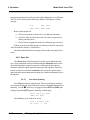
Choose System from the Function buttons. The LCD will display five
subfunctions.
TRAK/HLD Auto—Cal
PSWD Logout More
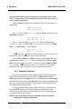
Use < > arrows to blink Auto—Cal, and press Enter. A new screen for
Span/Zero set appears.
Span OFF Nxt:
Zero OFF Nxt:
0d 0h
0d 0h
Press < > arrows to blink Span (or Zero), then press Enter again.
(You won’t be able to set OFF to ON if a zero interval is entered.) A Span
Every ... (or Zero Every ...) screen appears.
Span Every 0 d
Start 0 h from now
Use ∆∇ arrows to set an interval value, then use < > arrows to move to
the start-time value. Use ∆ ∇ arrows to set a start-time value.
To turn ON the Span and/or Zero cycles (to activate Auto-Cal): Press
System again, choose Auto—Cal, and press Enter again. When the Span/
Zero values screen appears, use the < > arrows to blink the Span (or Zero)
OFF/ON field. Use ∆ ∇ arrows to set the OFF/ON field to ON. You can now
turn these fields ON because there is a nonzero span interval defined.
4.3.3 Password Protection
If a password is assigned, then setting the following system parameters
can be done only after the password is entered: span and zero settings,
alarm setpoints, analysis range definitions, switching between autoranging
and manual override, setting up an auto-cal, and assigning a new password.
However, the instrument can still be used for analysis or for initiating a selftest without entering the password.
If you have decided not to employ password security, use the default
password TETAI. This password will be displayed automatically by the
microprocessor. The operator just presses the Enter key to be allowed total
access to the instrument’s features.
NOTE: If you use password security, it is advisable to keep a copy of the
password in a separate, safe location.
4-6
Teledyne Analytical Instruments
Ultra Trace Oxygen Analyzer
4.3.3.1
Operation 4
Entering the Password
To install a new password or change a previously installed password,
you must key in and ENTER the old password first. If the default password
is in effect, pressing the ENTER button will enter the default TETAI password for you.
Press System to enter the System mode.
TRAK/HLD Auto—Cal
PSWD Logout More
Use the < > arrow keys to scroll the blinking over to PSWD, and press
Enter to select the password function. Either the default TETAI password or
AAAAA place holders for an existing password will appear on screen depending on whether or not a password has been previously installed.
T E T A I
Enter PWD
or
A A A A A
Enter PWD
The screen prompts you to enter the current password. If you are not
using password protection, press Enter to accept TETAI as the default password. If a password has been previously installed, enter the password using
the < > arrow keys to scroll back and forth between letters, and the ∆ ∇
arrow keys to change the letters to the proper password. Press Enter to enter
the password.
If the password is accepted, the screen will indicate that the password
restrictions have been removed and you have clearance to proceed.
PSWD Restrictions
Removed
In a few seconds, you will be given the opportunity to change this
password or keep it and go on.
Change Password?
<ENT>=Yes
<ESC>=No
Press Escape to move on, or proceed as in Changing the Password,
below.
Teledyne Analytical Instruments
4-7
4 Operation
Model Ultra Trace 3000
4.3.3.2
Installing or Changing the Password
If you want to install a password, or change an existing password,
proceed as above in Entering the Password. When you are given the opportunity to change the password:
Change Password?
<ENT>=Yes
<ESC>=No
Press Enter to change the password (either the default TETAI or the
previously assigned password), or press Escape to keep the existing password and move on.
If you chose Enter to change the password, the password assignment
screen appears.
T E T A I
<ENT> To Proceed
or
A A A A A
<ENT> To Proceed
Enter the password using the < > arrow keys to move back and forth
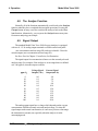
between the existing password letters, and the ∆ ∇ arrow keys to change the
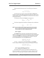
letters to the new password. The full set of 94 characters available for password use are shown in the table below.
Characters Available for Password Definition:
A
K
U
_
i
s
}
)
3
=
B
L
V
`
j
t
→
*
4
>
C
M
W
a
k
u
!
+
5
?
D
N
X
b
l
v
"
'
6
@
E
O
Y
c
m
w
#
7
F
P
Z
d
n
x
$
.
8
G
Q
[
e
o
y
%
/
9
H
R
¥
f
p
z
&
0
:
I
S
]
g
q
{
'
1
;
When you have finished typing the new password, press Enter. A
verification screen appears. The screen will prompt you to retype your
password for verification.
A A A A A
Retype PWD To Verify
4-8
Teledyne Analytical Instruments
J
T
^
h
r
|
(
2
<
Ultra Trace Oxygen Analyzer
Operation 4
Wait a moment for the entry screen. You will be given clearance to
proceed.
A A A A A
<ENT> TO Proceed
Use the arrow keys to retype your password and press Enter when
finished. Your password will be stored in the microprocessor and the system
will immediately switch to the Analyze screen, and you now have access to
all instrument functions.
If all alarms are defeated, the Analyze screen appears as:
0.0
Range:
ppm
Anlz
0 — 100
If an alarm is tripped, the second line will change to show which alarm
it is:
0.0
AL—1
ppm
Anlz
NOTE: If you log off the system using the logout function in the system
menu, you will now be required to re-enter the password to gain
access to Span, Zero, Alarm, and Range functions.
4.3.4 Logout
The Logout function provides a convenient means of leaving the
analyzer in a password protected mode without having to shut the instrument
off. By entering Logout, you effectively log off the instrument leaving the
system protected against use until the password is reentered. To log out,
press the System button to enter the System function.
TRAK/HLD Auto—Cal
PSWD Logout More
Use the < > arrow keys to position the blinking over the Logout
function, and press Enter to Log out. The screen will display the message:
Protected Until
Password Reentered
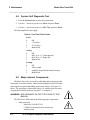
4.3.5 System Self-Diagnostic Test
The Model 3000 has a built-in self-diagnostic testing routine. Preprogrammed signals are sent through the power supply, output board and
sensor circuit. The return signal is analyzed, and at the end of the test the
Teledyne Analytical Instruments
4-9
4 Operation
Model Ultra Trace 3000
status of each function is displayed on the screen, either as OK or as a number between 1 and 3. (See System Self Diagnostic Test in chapter 5 for
number code.)
The self diagnostics are run automatically by the analyzer whenever the
instrument is turned on, but the test can also be run by the operator at will.
To initiate a self diagnostic test during operation:
Press the System button to start the System function.
TRAK/HLD Auto—Cal
PSWD Logout More
Use the < > arrow keys to blink More, then press Enter.
Version Self—Test
Neg-N
Filter-5
Use the < > arrow keys again to move the blinking to the SelfTest
function. The screen will follow the running of the diagnostic.
RUNNING DIAGNOSTIC
Testing Preamp — 83
During preamp testing there is a countdown in the lower right corner of
the screen. When the testing is complete, the results are displayed.
Power: OK
Preamp: 3
Analog: OK
The module is functioning properly if it is followed by OK. A number
indicates a problem in a specific area of the instrument. Refer to Chapter 5
Maintenance and Troubleshooting for number-code information. The results
screen alternates for a time with:
Press Any Key
To Continue...
Then the analyzer returns to the initial System screen.
4.3.6 Version Screen
Move the < > arrow key to More and press Enter. With Version
blinking, press Enter. The screen displays the manufacturer, model, and
software version information.
4-10
Teledyne Analytical Instruments
Ultra Trace Oxygen Analyzer
Operation 4
4.3.7 Filter Function
The response time on the most sensitive range (ppb range) is user
definable from approximately 1-60 minutes. The adjustable filter allows the
user to tune the response of the analyzer to best balance sensor noise and
response time requirements. The factory default setting is 5 minutes. The
actual response time will depend on the user’s sample system (the length and
size the tubing of tubing as well as the sample flow rate).
The filter setting can be accessed by selecting SYSTEM on the keypad
followed by MORE on the display with the <> keys. The filter function is
then selected and changed using the arrow keys. Press ENTER and ANALYZE to return to analyze mode.
In the event of an over-range condition, the filter rate will automatically
switch to a faster setting (approximately 45 sec. response time) for the
duration of the over-range or upset condition. This feature allows the analyzer to quickly respond to and track an upset condition.
4.4
Calibration of the Analyzer
The analyzer must be calibrated prior to its use. For most applications
where the desired range of measurement is 0 to 10 ppm, or less we
recommend the analyzer be calibrated using a span gas as detailed below:
Span Gas Calibration
Before the cell is ready for calibration, it must be purged with sample
gas to a low oxygen level preferably below 0.1 ppm. However, if the
oxygen contact of the sample gas is higher than 0.1 ppm, a zero gas such as
nitrogen with oxygen level below 0.1 ppm may be required.
The recommended span gas concentration is between 7.0 to 9.0 ppm
oxygen in nitrogen, and will require calibration be performed in the 0-10
ppm analyzer range.
4.4.1 Zero Cal
The B-2CXL cell has a zero offset of less than 0.1 ppm oxygen. Normally, the offset slowly decreases during the first 7 to 10 days of operation,
and is expected to reach a steady value after this time.
Teledyne Analytical Instruments
4-11
4 Operation
Model Ultra Trace 3000
Generally, the value of the zero offset is part of the oxygen reading of
the sample gas as shown by the analyzer readout. As an example, a reading
of 0.5 ppm oxygen may include 0.4 ppm oxygen in the sample gas and a 0.1
ppm zero offset.
The determination of the zero offset requires the use of oxygen free gas
to the analyzer. We recommend the use of nitrogen gas with a scrubber to
assure oxygen levels below 20 ppb.
The user may decide to eliminate the zero offset for improved accuracy. If so desired the analyzer is equipped to provide this function. However, we do not recommend carying out the cal zero during the first 10 days
of the operation of the cell.
The Zero button on the front panel is used to enter the zero calibration
function. Zero calibration can be performed in either the automatic or manual
mode. In the automatic mode, an internal algorithm compares consecutive
readings from the sensor to determine when the output is within the acceptable range for zero. In the manual mode, the operator determines when the
reading is within the acceptable range for zero. Make sure the zero gas is
connected to the instrument. If you get a CELL FAILURE message skip to
section 4.4.1.3.
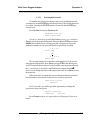
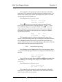
4.4.1.1
Auto Mode Zeroing
Press Zero to enter the zero function mode. The screen allows you to
select whether the zero calibration is to be performed automatically or manually. Use the ∆∇ arrow keys to toggle between AUTO and MAN zero settling. Stop when AUTO appears, blinking, on the display.
Zero: Settling: AUTO
<ENT> To Begin
Press Enter to begin zeroing.
####
PPM
Slope=####
Zero
ppm/s
The beginning zero level is shown in the upper left corner of the display. As the zero reading settles, the screen displays and updates information
on Slope (unless the Slope starts within the acceptable zero range and does
not need to settle further).
Then, and whenever Slope is less than 0.08 for at least 3 minutes,
instead of Slope you will see a countdown: 5 Left, 4 Left, and so fourth.
These are five steps in the zeroing process that the system must complete,
AFTER settling, before it can go back to Analyze.
4-12
Teledyne Analytical Instruments
Ultra Trace Oxygen Analyzer
Operation 4
####
PPM
4 Left=###
Zero
ppm/s
The zeroing process will automatically conclude when the output is
within the acceptable range for a good zero. Then the analyzer automatically
returns to the Analyze mode.
Because the reading of the slope is not very sensitive, it is recommended that zero gas be purging a few minutes before starting the Auto
mode zeroing. This will ensure cell stability on the new Zero settings.
4.4.1.2
Manual Mode Zeroing
Press Zero to enter the Zero function. The screen that appears allows
you to select between automatic or manual zero calibration. Use the ∆∇ keys
to toggle between AUTO and MAN zero settling. Stop when MAN appears,
blinking, on the display.
Zero: Settling: Man
<ENT> To Begin
Press Enter to begin the zero calibration. After a few seconds the first
of five zeroing screens appears. The number in the upper left hand corner is
the first-stage zero offset. The microprocessor samples the output at a predetermined rate. It calculates the differences between successive samplings and
displays the rate of change as Slope= a value in parts per million per second
(ppm/s).
####
ppm
Slope=####
Zero
ppm/s
NOTE: It takes several seconds for the true Slope value to display. Wait
about 10 seconds. Then, wait until Slope is sufficiently close to zero
before pressing Enter to finish zeroing .
Generally, you have a good zero when Slope is less than 0.05 ppm/s
for about 30 seconds. When Slope is close enough to zero, press Enter. In a
few seconds, the screen will update.
Once zero settling is completed, the information is stored in the
microprocessor, and the instrument automatically returns to the Analyze
mode.
4.4.1.3
Cell Failure
Cell failure in the Ultra Trace 3000 is usually associated with inability
to zero the instrument down to a satisfactorily low ppm reading corresponding to a current of 2 nanoamps (approx. 1 ppm). When this occurs, the
Teledyne Analytical Instruments
4-13
4 Operation
Model Ultra Trace 3000
instrument returns back to analyzer mode without taking the zero calibration.
The Ultra Trace 3000 system alarm trips, and the LCD displays a failure
message.
#.#
ppm
Anlz
CELL FAIL/ ZERO HIGH
Before replacing the cell:
a. Check your span gas to make sure it is within specifications.
b. Check for leaks up-stream from the cell, where oxygen may be
leaking into the system.
c. Check if more purging time with Zero calibration gas is needed.
If there are no leaks and the span gas is within specification, replace the
cell as described in chapter 5, Maintenance.
The failure alarm and failure message will reset after entering the Zero
mode.
4.4.2 Span Cal
The Span button on the front panel is used to span calibrate the analyzer. Span calibration can be performed using the automatic mode, where
an internal algorithm compares consecutive readings from the sensor to
determine when the output matches the span gas concentration. Span calibration can also be performed in manual mode, where the operator determines when the span concentration reading is acceptable and manually exits
the function.
4.4.2.1
Auto Mode Spanning
Press Span to enter the span function. The screen that appears allows
you to select whether the span calibration is to be performed automatically or
manually. Use the ∆ ∇ arrow keys to toggle between AUTO and MAN span
settling. Stop when AUTO appears, blinking, on the display.
Span: Settling: AUTO
<ENT> For Next
Press Enter to move to the next screen.
Calib. Holding time
Cal hold: 5 min
4-14
Teledyne Analytical Instruments
Ultra Trace Oxygen Analyzer
Operation 4
This menu allows the operator to set the time the analyzer should be
held in the AUTO span mode, after the readings of the analyzer settle. Five
minutes is the default, but it could be adjusted anywhere from 1 to 60 minutes by using the UP or DOWN keys.
Press Enter to move to the next screen.
Span Val: 008.00 ppm
<ENT>Span <UP>Mod #
Use the ∆ ∇ arrow keys to enter the oxygen-concentration mode
(999.99 ppm is maximum value of span gas allowed). Use the < > arrow
keys to blink the digit you are going to modify. Use the ∆∇ arrow keys
again to change the value of the selected digit. When you have finished
typing in the concentration of the span gas you are using, press Enter to
begin the Span calibration.
####
ppm
Slope=####
Span
ppm/s
The beginning span value is shown in the upper left corner of the
display. As the span reading settles, the screen displays and updates information on Slope. Spanning automatically ends when the span output corresponds, within tolerance, to the value of the span gas concentration. Then the
instrument automatically returns to the analyze mode.
4.4.2.2
Manual Mode Spanning
Press Span to start the Span function. The screen that appears allows
you to select whether the span calibration is to be performed automatically or
manually.
Span: Settling:MAN
<ENT> For Next
Use the ∆∇ keys to toggle between AUTO and MAN span settling. Stop
when MAN appears, blinking, on the display. Press Enter to move to the
next screen.
Press Enter to move to the next screen.
Calib. Holding time
Cal hold: 5 min
This menu allows the operator to set the time the analyzer should be
held in the AUTO span mode. It does not have any effect in the MANual
mode. Just press Enter key to continue.
Teledyne Analytical Instruments
4-15
4 Operation
Model Ultra Trace 3000
Span Val: 008.00ppm
<ENT>Span <UP>Mod #
Press ∆ (<UP>) to permit modification (Mod #) of span value.
Use the arrow keys to enter the oxygen concentration of the span gas
you are using (999.99 is maximum value of span gas). The < > arrows
choose the digit, and the ∆∇ arrows choose the value of the digit.
Press Enter to enter the span value into the system and begin the span
calibration.
Once the span has begun, the microprocessor samples the output at a
predetermined rate. It calculates the difference between successive samplings
and displays this difference as a Slope on the screen. It takes several seconds
for the first Slope value to display. Slope indicates the rate of change of the
Span reading. It is a sensitive indicator of stability.
####
Slope=####
%
Span
ppm/s
When the Span value displayed on the screen is sufficiently stable,
press Enter. (Generally, when the Span reading changes by 1 % or less of
the full scale of the range being calibrated, for a period of ten minutes it is
sufficiently stable.) Once Enter is pressed, the Span reading changes to the
correct value. The instrument then automatically enters the Analyze function.
4.4.3
Span Failure
The analyzer checks the output of the cell at the end of the span. If the
raw output of the cell is less than 0.5 uA/ppm O2, the span will not be
accepted. The analyzer will return to the previous calibration values, trigger
the System Alarm, and display in the VFD:
Span Failed!!
This message will be shown for five seconds and the instrument shall
return to the Analyze mode. In the upper right hand corner of the VFD
display “FCAL” will be shown. This message flag will help the operator
troubleshoot in case calibration was initiated remotely. To reset the alarm
and the flag message, the analyzer must be properly spanned.
A trace cell is unlikely to fail span. As explained before, when the
sensor reaches the end of its useful life, the zero offset begins to rise until the
analyzer finds the zero unsatisfactory. Nevertheless, feeding the wrong span
4-16
Teledyne Analytical Instruments
Ultra Trace Oxygen Analyzer
Operation 4
gas or electronics failure could set this feature off at the end of the span.
Consider this before replacing the cell.
4.5
Switching of Sample Streams
The Model Ultra Trace 3000 may be used to monitor more than one
type of sample gas, such as nitrogen and helium, or two streams of nitrogen
containing low (less than 1 ppm) and high (500 to 1000 ppm) concentrations
of oxygen.
For these applications, we recommend the following parameters and
conditions be followed:
1. While switching streams, such as between nitrogen and helium, both
the gas streams must be made to flow continuosly even through only one
stream is going through the analyzer at one time. Failure to do so may result
in spikes in output when the dead-ended stream is switched in. For more
discussion of this, read the Technical Bulletin - TB00001, dated 3-98. This
Bulletin is available upon request from TATAI.
2. The analyzer is capable of handling the switching of streams without
effecting the sensitivity of the cell. This switching of streams between
nitrogen and helium will not require SPAN adjustment. However, care must
be taken to keep sample flow rates in the desired levels, as the flowmeter is
calibrated for air and nitrogen streams only.
3. The analyzer can withstand repeated switching of streams between
low oxygen levels of less than 1 ppm and high oxygen levels of 5000 to
1000 ppm. Again, care must be taken to ensure proper and continuous flows
at all times.
4.5.1
Special Notes on Hydrogen Gas Stream
The standard oxygen cell, Model B-2CXL, though tested in nitrogen
gas streams is expected to perform well in hydrogen streams. However, for
certain applications such as continuous monitoring of very low levels of
oxygen in hydrogen, the user may request cells that have been specifically
tested in hydrogen streams. Consult Teledyne for further details.
4.6
The Alarms Function
The Model Ultra Trace 3000 is equipped with 2 fully adjustable concentration alarms and a system failure alarm. Each alarm has a relay with a
Teledyne Analytical Instruments
4-17
4 Operation
Model Ultra Trace 3000
set of form “C" contacts rated for 3 amperes resistive load at 250 V ac. See
Figure 3-5 in Chapter 3, Installation and/or the Interconnection Diagram
included at the back of this manual for relay terminal connections.
The system failure alarm has a fixed configuration as described in
chapter 3 Installation.
The concentration alarms can be configured from the front panel as
either high or low alarms by the operator. The alarm modes can be set as
latching or non-latching, and either failsafe or non-failsafe, or, they can be
defeated altogether. The setpoints for the alarms are also established using
this function.
Decide how your alarms should be configured. The choice will depend
upon your process. Consider the following four points:
1. Which if any of the alarms are to be high alarms and which if any
are to be low alarms?
Setting an alarm as HIGH triggers the alarm when the oxygen
concentration rises above the setpoint. Setting an alarm as LOW
triggers the alarm when the oxygen concentration falls below the
setpoint.
Decide whether you want the alarms to be set as:
• Both high (high and high-high) alarms, or
• One high and one low alarm, or
• Both low (low and low-low) alarms.
2. Are either or both of the alarms to be configured as failsafe?
In failsafe mode, the alarm relay de-energizes in an alarm
condition. For non-failsafe operation, the relay is energized in an
alarm condition. You can set either or both of the concentration
alarms to operate in failsafe or non-failsafe mode.
3. Are either of the alarms to be latching?
In latching mode, once the alarm or alarms trigger, they will
remain in the alarm mode even if process conditions revert back
to non-alarm conditions. This mode requires an alarm to be
recognized before it can be reset. In the non-latching mode, the
alarm status will terminate when process conditions revert to nonalarm conditions.
4. Are either of the alarms to be defeated?
The defeat alarm mode is incorporated into the alarm circuit so
that maintenance can be performed under conditions which
would normally activate the alarms.
4-18
Teledyne Analytical Instruments
Ultra Trace Oxygen Analyzer
Operation 4
The defeat function can also be used to reset a latched alarm.
(See procedures, below.)
If you are using password protection, you will need to enter your
password to access the alarm functions. Follow the instructions in section
4.3.3 to enter your password. Once you have clearance to proceed, enter the
Alarm function.
Press the Alarm button on the front panel to enter the Alarm function.
Make sure that AL1 is blinking.
AL—1
AL—2
Choose Alarm
Set up alarm 1 by moving the blinking over to AL–1 using the < >
arrow keys. Then press Enter to move to the next screen.
AL—1 10.000
Dft—N Fs—N
ppm HI
Ltch—N
Five parameters can be changed on this screen:
• Value of the alarm setpoint, AL–1 #### ppm (oxygen);
value can be set from 0 to 999 ppb + 1.000-1000.00 ppm.
• Out-of-range direction, HI or LO
• Defeated? Dft–Y/N (Yes/No)
• Failsafe? Fs–Y/N (Yes/No)
• Latching? Ltch–Y/N (Yes/No).
• To define the setpoint, use the < > arrow keys to move the
blinking over to AL–1 ####. Then use the ∆∇ arrow keys to
change the number. Holding down the key speeds up the
incrementing or decrementing. (Remember, the setpoint units are
ppm O2.)
• To set the other parameters use the < > arrow keys to move the
blinking over to the desired parameter. Then use the ∆∇ arrow
keys to change the parameter.
• Once the parameters for alarm 1 have been set, press Alarms
again, and repeat this procedure for alarm 2 (AL–2).
• To reset a latched alarm, go to Dft and then press either ∆ two
times or ∇ two times. (Toggle it to Y and then back to N.)
–OR –
Go to Ltch and then press either ∆ two times or ∇ two times.
(Toggle it to N and back to Y.
Teledyne Analytical Instruments
4-19
4 Operation
Model Ultra Trace 3000
Alarm Hysterisis: There is alarm hysterisis to prevent chatter of the
alarm contacts. It is set to 0.2 ppm for alarms set above 1 ppm,
and 10 ppb for alarms set below 1 ppm.
4.7
The Range Function
The Range function allows the operator to program up to three concentration ranges to correlate with the DC analog outputs. If no ranges are
defined by the user, the instrument defaults to:
Low = 0–250 ppb
Med = 0–1 ppm
High = 0–10 ppm.
The Model Ultra Trace 3000 is set at the factory to default to
autoranging. In this mode, the microprocessor automatically responds to
concentration changes by switching ranges for optimum readout sensitivity.
If the current range limits are exceeded, the instrument will automatically
shift to the next higher range. If the concentration falls to below 90% of full
scale of the next lower range, the instrument will switch to that range. A
corresponding shift in the DC percent-of-range output, and in the range ID
outputs, will be noticed.
The autoranging feature can be overridden so that analog output stays
on a fixed range regardless of the oxygen concentration detected. If the
concentration exceeds the upper limit of the range, the DC output will
saturate at 1 V dc (20 mA at the current output).
However, the digital readout and the RS-232 output of the concentration are unaffected by the fixed range. They continue to read accurately with
full precision. See Front Panel description in Chapter 1.
The automatic fourth range is always 0-1000 ppm and is not programmable.
4.7.1 Setting the Analog Output Ranges
To set the ranges, enter the range function mode by pressing the
Range button on the front panel.
L—250 ppb
M—1 ppm
H—10 ppm Mode—AUTO
Use the < > arrow keys to blink the range to be set: low (L), medium
(M), or high (H).
4-20
Teledyne Analytical Instruments
Ultra Trace Oxygen Analyzer
Operation 4
Use the ∆∇ arrow keys to enter the upper value of the range (all ranges
begin at 0). Repeat for each range you want to set. Press Enter to accept the
values and return to Analyze mode. (See note below.)
Note:
The ranges must be increasing from low to high, for example, if range
1 is set as 0–500 ppb and range 2 is set as 0–10 ppm, range 3 cannot
be set as 0– 5 ppm since it is lower than range 2.
Ranges, and alarms, are set in ppb or ppm units depending on concentration. All concentration-data outputs change from ppb units to ppm when
the concentration is above 1.0 ppm. Range Low (L) is always a ppb range
and cannot be set higher than 1000 ppb nor lower than 10 ppb. Ranges
medium (M) and High (H) can only be set in ppm. The Medium (M) range
can be set between 1 and 10 ppm, while the high (H) range can be set
between 10 and 1000 ppm.
4.7.2 Fixed Range Analysis
The autoranging mode of the instrument can be overridden, forcing the
analyzer DC outputs to stay in a single predetermined range.
To switch from autoranging to fixed range analysis, enter the range
function by pressing the Range button on the front panel.
Use the < > arrow keys to move the blinking over AUTO.
Use the ∆∇ arrow keys to switch from AUTO to FX/L, FX/M, or FX/H to
set the instrument on the desired fixed range (low, medium, or high).
L—250ppb
H—10 ppm
M—1 ppm
Mode—FX/L
or
L—250 ppb
H—10 ppm
M—1 ppm
Mode—FX/M
or
L—250 ppb
H—10 ppm
M—1 ppm
Mode—FX/H
Press Escape to re-enter the Analyze mode using the fixed range.
NOTE: When performing analysis on a fixed range, if the oxygen concentration rises above the upper limit (or default value) as established by the
operator for that particular range, the output saturates at 1 V dc (or 20
mA). However, the digital readout and the RS-232 output continue to
read the true value of the oxygen concentration regardless of the
analog output range.
Teledyne Analytical Instruments
4-21
4 Operation
4.8
Model Ultra Trace 3000
The Analyze Function
Normally, all of the functions automatically switch back to the Analyze
function when they have completed their assigned operations. Pressing the
Escape button in many cases also switches the analyzer back to the Analyze function. Alternatively, you can press the Analyze button at any time
to return to analyzing your sample.
4.9
Signal Output
The standard Model Ultra Trace 3000 Oxygen Analyzer is equipped
with two 0–1 V dc analog output terminals accessible on the back panel
(one concentration and one range ID), and two isolated 4–20 mA dc
current outputs (one concentration and one range ID).
See Rear Panel in Chapter 3, Installation, for illustration.
The signal output for concentration is linear over the currently selected
analysis range. For example, if the analyzer is set on range that was defined
as 0–100 ppm O2, then the output would be:
ppm O2
Voltage Signal
Output (V dc)
0
10
20
30
40
50
60
70
80
90
100
0.0
0.1
0.2
0.3
0.4
0.5
0.6
0.7
0.8
0.9
1.0
Current Signal
Output (mA dc)
4.0
5.6
7.2
8.8
10.4
12.0
13.6
15.2
16.8
18.4
20.0
The analog output signal has a voltage which depends on the oxygen
concentration AND the currently activated analysis range. To relate the
signal output to the actual concentration, it is necessary to know what range
the instrument is currently on, especially when the analyzer is in the
autoranging mode.
4-22
Teledyne Analytical Instruments
Ultra Trace Oxygen Analyzer
Operation 4
To provide an indication of the range, a second pair of analog output
terminals are used. They generate a steady preset voltage (or current when
using the current outputs) to represent a particular range. The following table
gives the range ID output for each analysis range:
Range
LO
Voltage (V)
0.25
Current (mA)
8
MED
0.50
12
HI
0.75
16
(0-1000ppm)
1.00
20
Teledyne Analytical Instruments
4-23
4 Operation
4-24
Model Ultra Trace 3000
Teledyne Analytical Instruments
Ultra Trace Oxygen Analyzer
Maintenance 5
Maintenance
5.1
Routine Maintenance
Aside from normal cleaning and checking for leaks at the gas connections, routine maintenance is limited to replacing Micro-Fuel cells and fuses,
and recalibration. For recalibration, see Section 4.4 Calibration.
WARNING: SEE WARNINGS ON THE TITLE PAGE OF THIS
MANUAL.
5.2
Cell Replacement
The B-2CXL Micro-Fuel Cell is a sealed electrochemical transducer
with no electrolyte to change or electrodes to clean. When the cell reaches
the end of its useful life, it is replaced. The spent fuel cell should be discarded according to local regulations. This section describes fuel cell care as
well as when and how to replace it.
5.2.1 Storing and Handling Replacement Cells
To have a replacement cell available when it is needed, TAI recommends that one spare cell be purchased 9-10 months after commissioning the
Ultra Trace 3000, or shortly before the end of the cell's one year warranty
period.
CAUTION: Do not stockpile cells. The warranty period starts on
the day of shipment.
The spare cell should be carefully stored in an area that is not subject to
large variations in ambient temperature (75 °F nominal) or to rough handling.
Teledyne Analytical Instruments
5-1
5 Maintenance
Model Ultra Trace 3000
WARNING: THE SENSOR USED IN THE MODEL 3000 TRACE
OXYGEN ANALYZER USES ELECTROLYTES
WHICH CONTAIN TOXIC SUBSTANCES, MAINLY
LEAD AND POTASSIUM HYDROXIDE, THAT CAN
BE HARMFUL IF TOUCHED, SWALLOWED, OR
INHALED. AVOID CONTACT WITH ANY FLUID OR
POWDER IN OR AROUND THE UNIT. WHAT MAY
APPEAR TO BE PLAIN WATER COULD CONTAIN
ONE OF THESE TOXIC SUBSTANCES. IN CASE OF
EYE CONTACT, IMMEDIATELY FLUSH EYES WITH
WATER FOR AT LEAST 15 MINUTES. CALL PHYSICIAN. (SEE APPENDIX, MATERIAL SAFETY DATA
SHEET.)
CAUTION: Do not disturb the integrity of the cell package until
the cell is to actually be used. If the cell package is
punctured and air is permitted to enter, the cell will
require an excessively long time to reach zero after
installation (1-2 weeks!).
5.2.2 When to Replace a Cell
Cell failure in the Ultra Trace 3000 is usually characterized by a
significant increase in the zero offset of more than 1.0 ppm (2 nanoamps
sensor output approximately) oxygen or the inability to calibrate the sensor.
When this occurs, the Ultra Trace 3000 will still Zero but the system alarm
trips, and the LCD displays a failure message.
#.#
ppm
Anlz
CELL FAIL/ ZERO HIGH
Before replacing the cell:
a. Check your span and zero gas to make sure it is within
specifications.
b. Check for leaks up-stream from the cell, where oxygen may be
leaking into the system.
c. Check if more purging time with zero calibration gas is needed.
If there are no leaks and the span gas is within specification, replace the
cell.
The failure alarm and the failure message will reset after re-entering the
zero mode again.
5-2
Teledyne Analytical Instruments
Ultra Trace Oxygen Analyzer
Maintenance 5
5.2.3 Removing the Micro-Fuel Cell
The Micro-Fuel cell is located inside the stainless steel cell block behind
the front panel (see Figure 5-1). To remove an existing cell:
1. Remove power to the instrument by unplugging the power cord
at the power source.
2. Open the front panel door by pressing the release button on the
top right corner of the door all the way in with a narrow gauge
tool.
3. With one hand hold the top of the cell block while unscrewing
the plastic ring holder. Once the plastic ring is loose, remove the
top of the cell block.
COLLAR
CELL BLOCK
SENSOR
O-RING
CELL HOLDER
Figure 5-1: Removing the Micro-Fuel
Teledyne Analytical Instruments
5-3
5 Maintenance
Model Ultra Trace 3000
5.2.4 Installing a New Micro-Fuel Cell
Before installing a new cell, check the O-ring in the base of the cell
holder. Replace if worn or damaged.
1. Verify that the 0-ring is properly located.
2. Place the cell on cell holder with the screen side facing down.
3. Place the cell block on top of the cell holder.
4. Hold the cell block with one hand and rotate the collar clockwise.
5. To determine if the assembly is fully seated, rotate the cell block
slightly.
6. When fully seated, the cell block can be rotated with three fingers
but considerable drag will be felt.
5.2.5 Cell Warranty
The Class B-2CXL Micro-Fuel cell is used in the Model Ultra Trace
3000. This cell is warranted for 6 months from the date of shipment. Note
any Addenda attached to the front of this manual for special information
applying to your instrument.
With regard to spare cells, warranty period begins on the date of shipment. The customer should purchase only one spare cell (per section 5.2.1).
Do not attempt to stockpile spare cells.
The B-2CXL cell is not designed for applications where CO2 is a
major component in the sample, however concentrations of 1,000 ppm or
less will not adversely effect the cell performance. Consult TAI for the
appropriate cell for measuring trace oxygen in the presence of CO2.
If a cell was working satisfactorily, but ceases to function before the
warranty period expires, the customer will receive credit toward the purchase
of a new cell.
If you have a warranty claim, you must return the cell in question to the
factory for evaluation. If it is determined that failure is due to faulty workmanship or material, the cell will be replaced at no cost to you.
Note: Evidence of damage due to tampering or mishandling will
render the cell warranty null and void.
5-4
Teledyne Analytical Instruments
Ultra Trace Oxygen Analyzer
5.3
Maintenance 5
Fuse Replacement
1. Place small screwdriver in notch, and pry cover off, as shown in
Figure 5-2.
Figure 5-2: Removing Fuse Block from Housing
2. To change between American and European fuses, remove the
single retaining screw, flip Fuse Block over 180 degrees, and
replace screw.
3. Replace fuse as shown in Figure 5-3.
4. Reassemble Housing as shown in Figure 5-2.
American Fuses
European Fuses
Figure 5-3: Installing Fuses
Teledyne Analytical Instruments
5-5
5 Maintenance
5.4
Model Ultra Trace 3000
System Self Diagnostic Test
1. Press the System button to enter the system mode.
2. Use the < > arrow keys to move to More, and press Enter.
3. Use the < > arrow keys to move to Self-Test, and press Enter.
The following failure codes apply:
Table 5-1: Self Test Failure Codes
Power
0
1
2
3
OK
5 V Failure
15 V Failure
Both Failed
Analog
0
1
2
3
OK
DAC A (0–1 V Concentration)
DAC B (0–1 V Range ID)
Both Failed
Preamp
0
1
2
3
5.5
OK
Zero too high
Amplifier output doesn't match test input
Both Failed
Major Internal Components
The Micro-Fuel cell is accessed by unlatching and swinging open the
front panel, as described earlier. Other internal components are accessed by
removing the rear panel and sliding out the entire chassis. See Figure 5-4,
below. The gas piping is illustrated in Figure 2-4, and the major electronic
components locations are shown in Figure 2-5, in chapter 2.
WARNING: SEE WARNINGS ON THE TITLE PAGE OF THIS
MANUAL.
The Ultra Trace 3000 contains the following major components:
• Analysis Section
Micro Fuel Cell (B-2CXL)
Cell block with stainless steel wetted parts
Sample system
5-6
Teledyne Analytical Instruments
Ultra Trace Oxygen Analyzer
•
•
•
•
•
•
Maintenance 5
TEC cooler assembly
Power Supplys
Microprocessor
Displays
5 digit LED meter
2 line, 20 character, alphanumeric, VFD display
RS-232 Communications Port.
TEC temperature controller PCB
See the drawings in the Drawings section in back of this manual
for details.
X
X
X
X
X
Te le d y n e A n aly tic a l In s tru m e n ts
X
X
X
X
X
Figure 5-4: Rear-Panel Screws
To detach the rear panel, remove only the 14 screws marked with an X.
5.6
Cleaning
If instrument is unmounted at time of cleaning, disconnect the instrument from the power source. Close and latch the front-panel access door.
Clean outside surfaces with a soft cloth dampened slightly with plain clean
water. Do not use any harsh solvents such as paint thinner or benzene.
For panel-mounted instruments, clean the front panel as prescribed in
the above paragraph. DO NOT wipe front panel while the instrument is
controlling your process.
Teledyne Analytical Instruments
5-7
5 Maintenance
5.7
Model Ultra Trace 3000
Troubleshooting
Problem:
Erratic readings of the Oxygen concentration as reported by the analyzer.
Possible Cause:
The analyzer may have been calibrated in an inaccurate fashion.
Solution:
Turn the analyzer off, then turn back on again. Press the System key when
prompted by the analyzer "Press System for default Values". This will
return the analyzer to its default settings in calibration and zero values. If
erratic behavior continues clean sensor contacts or replace the sensor.
Possible Cause:
Atmospheric Oxygen may be diffusing in through the vent and affecting the
oxygen level which the sensor sees.
Solution:
Increase flow rate and/or length or vent tubing in order to dilute or minimize
the diffusion of oxygen from the vent back to the sensor.
Problem:
Inaccurate zero operation (i.e. the user has zeroed the analyzer accidentally
on gas much higher than one would normally use for a zero gas).
Solution:
Turn the analyzer off, then back on again. Press the System key when
prompted by the analyzer "Press System for default Values". This will
return the analyzer to its default settings in calibration and zero values. Now
proceed to carefully calibrate and zero the analyzer.
5-8
Teledyne Analytical Instruments
Ultra Trace Oxygen Analyzer
Appendix
Appendix
A-1
Specifications
Packaging: General Purpose
• Flush panel mount (Standard).
• Relay rack mount. Contains one
instrumentsin one 19" relay rack mountable
plate (Optional).
Sensor: Teledyne B-2CXL trace analysis Micro-Fuel
Cell.
Cell Block: 316 stainless steel.
Sample System: All wetted parts of 316 stainless steel.
90 % Response Time: Less than 30 seconds at 25 °C (77 °F) on 10
ppm range.
120 seconds on 250 ppb range, programmable
response in ppb range.
Ranges: Three user definable ranges from 0–250 ppb to
0–1,000 ppm, plus over range of 0-1,000 ppm.
Autoranging with range ID output.
Alarms: One system-failure alarm contact to detect
power failure or sensor-zero and span failure.
Two adjustable concentration threshold alarm
contacts with fully programmable setpoints.
Displays: 2-line by 20-character, VFD screen, and one 5
digit LED display.
Digital Interface: Full duplex RS-232 communications port.
Teledyne Analytical Instruments
A-1
Appendix
Model Ultra Trace 3000
Power: Universal power supply 85-250 V ac, at
47-63 Hz.
Operating Temperature: 5-40 °C
Accuracy: ±2% of full scale for all ranges except 0-250
ppb range, at constant temperature.
For 0-250 ppb range accuracy is as follows:
±5 ppb at constant temperature.
±10 ppb over temperature variation of 20° 30°C.
±15 ppb over temperature variation of 15° 35°C.
All accuracy specifications are contingent
upon the completion of zero ans span calibration.
All accuracy is established at constant pressure and equilibrium has been established.
Analog outputs: 0-1 V dc percent-of-range,
0-1 V dc range ID.
4-20 mA dc (isolated) percent-of-range,
4-20 mA dc (isolated) range ID.
Dimensions: 19 cm high, 24.9 cm wide, 31 cm deep (6.96
in high, 8.7 in wide, 12.2 in deep).
A-2
Teledyne Analytical Instruments
Ultra Trace Oxygen Analyzer
Appendix
A-2 Recommended 2-Year Spare Parts List
QTY.
PART NUMBER
DESCRIPTION
1
CP2037
TEC Cooler
1
C65507
Back Panel Board
1
C62371-B
Front Panel Board
1
C71410
Preamplifier Board (Instruction)
1
C70941
TEC Controller PCB
1
C62365-A
Main Computer Board
3
F9
Fuse, 1A, 250V 3AG Slow Blow
3
F1275
Fuse, 1A, 250V 5x20mm (European)
Slow Blow
1
O286
O-ring
1
C6689-B2CXL
Micro-Fuel Cell (do not store for more
than 6 months)
1
CP1798
50 pin D-sub interface connector
1
F1498
Fan
50
CP1799
Pins for CP1798 connector
A minimum charge is applicable to spare parts orders.
Note:
Orders for replacement parts should include the part number (if
available) and the model and serial number of the instrument for
which the parts are intended.
Orders should be sent to:
Teledyne Analytical Instruments
16830 Chestnut Street
City of Industry, CA 91749-1580
Phone (626) 934-1500, Fax (626) 961-2538
TWX (910) 584-1887 TDYANYL COID
Web: www.teledyne-ai.com
or your local representative.
Teledyne Analytical Instruments
A-3
Appendix
Model Ultra Trace 3000
A-3 Drawing List
B-71228
Piping Diagram
A-4 19-inch Relay Rack Panel Mount
Figure A-1: Single 19" Rack Mounts
A-4
Teledyne Analytical Instruments
8.72
5.75
(dimensions in mm)
Ultra Trace Oxygen Analyzer
A-5
Appendix
Ultra Trace 3000 SERIES ANALYZERS
APPLICATION NOTES ON
PRESSURES AND FLOW RECOMMENDATIONS
3000 series analyzers require reasonably regulated sample pressures.
While the 3000 analyzers are not sensitive to variations of incoming pressure
(provided they are properly vented to atmospheric pressure) The pressure must
be maintained as to provide a useable flow rate trough the analyzer. Any line
attached to sample vent should be 1/4 or larger in diameter.
FLOW RATE RECOMMENDATIONS:
A usable flow rate for a 3000 series analyzer is one which can be
measured on the flowmeter. This is basically 0.5 - 2.0 SLPM . The optimum
flow rate is 1 SLPM (mid scale). Note: response time is dependent on flow
rate, a low flow rate will result in slow response to O2 changes in the sample
stream. The span flow rate should be the approximately same as the sample flow
rate.
CELL PRESSURE CONCERNS:
The sensors used in 3000 series analyzers are optimized to function at
atmospheric pressure. At pressures other than atmospheric the diffusion rate of
O2 will be different than optimum value. Higher pressures will produce faster O2
diffusion rates resulting in higher O2 reading and shorter cell life. To use a 3000
series analyzer at a cell pressure other than atmospheric, the analyzer must be
calibrated with a known calibration gas at the new cell pressure to adjust for the
different diffusion rate. Cell pressures below 2/3 atmospheric are not
recommended because they tend to cause excessive internal expansion which
may result in seal failure.
For operation at cell pressures other than atmospheric care must be
taken not to change the sample pressure rapidly or cell damage may occur. For
cell pressures above atmospheric, caution must be exercised to avoid over
pressuring the cell holder.
FLOW CONTROL VALVE:
All 3000 series analyzers have a flow control device. This device is a
needle valve, and serves two functions in the sample path. The first function is to
limit the flow rate of the sample through the analyzer. The needle valve is chosen
to operate over a specific range of pressures and provide a useable flow rate
over that range.
The second function that the needle valve provides is a pressure drop.
This device is selected to provide the only significant pressure drop in the
sample path.
Teledyne Analytical Instruments
A-5
Appendix
Model Ultra Trace 3000
BY-PASS:
To improve the system response, a by-pass can be added to increase
the sample flow rate to the analyzer by a factor of ten. A by-pass provides a
sample flow path around the analyzer of 2 - 18 SCFH. typically.
CONVERSIONS:
1 PSI
1 SCFH
NOTE:
A-6
=
=
2.04 INCHES OF MERCURY (in. Hg.)
0.476 SLPM
The MSDS on this material is available upon request
through the Teledyne Environmental, Health and
Safety Coordinator. Contact at (626) 934-1592
Teledyne Analytical Instruments