1
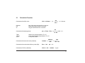
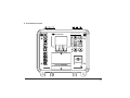
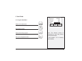
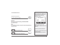
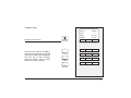
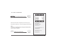
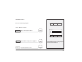
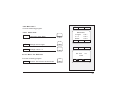
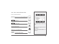
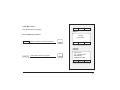
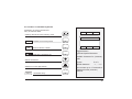
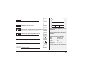
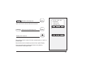
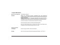
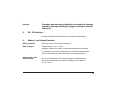
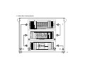
PEM 9002
Portable Emissions Monitor
(US - Version, V1.0)
16830 Chestnut Street City of Industry,
California 91748, USA
TEL: 626-934-1500
TOLL FREE: 888-789-8168
FAX: 626-934-1651
www.teledyne-ai.com
WARRANTY SUMMARY
Teledyne warrants that the products it manufactures will be free from defects
in materials and workmanship for a period of one year from the date of delivery
from factory.
If a product proves defective within the respective period, Teledyne will provide
repair or replacement as described in the complete warranty statement.
To arrange for service or obtain a copy of the complete warranty statement,
please contact your nearst Teledyne distributor.
EXCEPT AS PROVIDED IN THIS SUMMARY OR THE APPLICABLE
WARRANTY STATEMENT, TELEDYNE MAKES NO WARRANTY OF
ANY KIND, EXPRESS OR IMPLIED,INCLUDING WITHOUT LIMITATION THE IMPLIED WARRANTIES OR MERCHANTABILITY AND
FITNESS FOR A PARTICULAR PURPOSE. IN NO EVENT SHALL
TELEDYNE BE LIABLE FOR INDIRECT, SPECIAL OR CONSEQUENTIAL DAMAGES.
Table of Contents
1
2
2.1
Page
Product Description............................... .2
Physical Data..........................................5
Calculation Formulae ............................. 6
3
Technical Data ........................................7
4
Front Panel Overview ...........................10
5
Keypad Functions .................................11
6
User Guide ...........................................12
6.1
6.2
6.3
6.4
6.5
Program Start Menu ..............................12
Calibration Menu ...................................13
Fuel Selection .......................................14
Additional Functions/Meas. Program....15
Draft Measurement ...............................16
6.6
6.6.1
6.6.1.1
6.6.1.2
Menu Lines............................................17
Menu Line 1...........................................18
Menu - Info Box.....................................19
Menu - Time and Date...........................20
6.6.2 Menu Line 2...........................................21
6.6.2.1 Menu - Graphic .....................................21
Page
6.6.2.2 Menu - Core Of Waste Gas Flow ..........22
6.6.2.3 Menu - CO Purge System (manual)........22
6.6.3
6.6.3.1
6.6.3.2
6.6.3.3
Menu Line 3 ..........................................23
Menu - Units ..........................................23
Menu - O2-Ref.......................................23
Menu - Add. Data...................................24
6.6.4
6.6.4.1
6.6.4.2
6.6.4.3
6.6.4.4
Menu Line 4 .........................................25
Memory Functions.................................25
Menu - Create memory blocks ...............29
Menu - Delete memory data...................32
Printing the Measured Values ................34
6.7
Configuration Menu ..............................35
6.8
Entering the Company Address ............37
7
System Maintenance ............................38
8
RS 232 Interface ...................................39
9
Battery / Line Power Operation..............39
10
Loading Paper ......................................42
11
11.1
Waste Gas Cleaning System .................43
Filters And Other Cleaner Parts..............44
1
1.
Product Description
The Gas Analysis Computer is a multiple -function analyzer with integrated calculating functions.
Measurements are in accordance with the general regulations set forth by the BIMSchV (German
Regulations concerning the protection against harmful effects on the environment) at all kinds of
combustion plants within the framework of the monitoring of exhaust systems.
a) Measurement and calculation parameters for monitoring exhaust systems and for determining
the efficiency of combustion plants:
Measured Values:
T.Gas
T.Room
O2
CO
NO
SO2
Draft
Waste or flue gas temperature
Air or ambient temperature
Oxygen content
Carbon monoxide
Nitrogen monoxide (Option)
Sulphur dioxide (Option)
Draft or Pressure
°F or °C
°F or °C
% Volume
ppm - mg/m³ - mg/kWh
ppm - mg/m³ - mg/kWh
ppm - mg/m³ - mg/kWh
inches of H2O (iWC)
Calculated Values:
CO2
CO 0%
Effi.
Ex.air
Losses
NOx
T.Diff
Carbon dioxide
Carbon monoxide, undiluted
Combustion efficiency
Excess air value
Waste gas losses
Nitrogen oxides (optional)
Differential temperature (TG-TA)
% Volume
ppm
%
%
ppm - mg/m³ - mg/kWh
°F or °C
2
b) Measuring Procedure
Temperature Measurem.: K-type thermocouple (NiCr-Ni) for waste or flue gas temperature
K-type thermocouple (NiCr-Ni) for air or ambient temperature.
O2-Measurement :
Electrochemical measuring cell.
CO-Measurement :
Electrochemical measuring cell.
Draft Measurement :
Piezo-resistive principle with internal temperature compensation.
Measuring Duration:
Short-term memory measurements of max. 60 minutes are possible, followed by
a new calibration phase with ambient air.
Waste Gas Measurement : Via an external water separator and filter, the waste gas is fed to the sensors by
means of a gas feed pump. The pump capacity during the feeding phase is
approx. 0.8 l/min.
Sensor Calibration:
60 seconds after switching on the instrument.
CO Concentration:
CO sensor with H2 compensation, measuring range 0 - 4.000 ppm. Cutoff
threshold at 4.000 ppm for sensor protection via separate flush pump.
The remaining measuring values are not affected. The instrument is switched on
again at a value of 1.600 ppm.
Waste Gas Sampling:
By means of a waste gas sampling probe with retainer cone.
3
c) Instrument Description
Electrical Supply:
NiCad battery 6V/4.0 Ah, external charger.
Display:
With backlight; alphanumeric and graphic display.
4 lines of 16 characters each, plus menu line.
Computer Interface:
RS 232.
Printer Interface:
Pin Printer (Normal Paper).
Printer:
External infrared thermo-paper printer.
Memory:
100 memory blocks
Adm. Operating Temp.:
+ 40 °F to + 104 °F (+ 5°C to + 40°C).
Adm. Storage Temp.:
-22 °F to + 140 °F (- 30°C to + 50 °C).
Mech. Dimensions:
10.6” x 9.6” x 6.9” (270 x 245 x 175 mm).
Weight:
8.0 lbs (3,8 kg).
Standard Version:
Instrument, battery charger, combined flue gas temperature
probe / watertrap and hose assembly with measuring cone,
ambient air temperature sensor, carrying case and manual.
4
2.
Physical Data
Measuring ranges:
CO
0 ... 4.000 ppm
CO-0%
0 ... 9.999 ppm
O2
0 ... 20,9 % Volume
T.Gas
+ 32 °F to + 1.850 °F (0 °C ... + 1.000 °C)
T.Room
-5 °F to + 212 °F (- 20 °C ... +100 °C)
Draft/Pressure
± 60 inches of H2O (± 150.0 hPa)
CO2
0,0 ... CO2 max % Volume
Losses
0 ... 100%
Efficiency
100 ... 0%
Excess air
1 ... 99.999.
NO x, NO
0 ... 2.000 ppm
SO 2, NO
0 ... 2.000 ppm
CO High
0 ... 1.0 % Volume (10.000 ppm)
(General Specifications)
Optional:
5
2.1
Calculation Formulae
Calculation of the CO2 value:
CO2max:
O2:
21:
O2
( 1 - ------- )
20.9
in % Volume
Max. CO2-value (fuel-specific) in % Volume.
Measured oxygen content in % Volume.
Oxygen content of the air in % Volume.
Calculation of the waste gas loss:
T.Gas:
T.Room:
A2, B:
CO2 = CO2max *
A2
qA = ( T.Gas - T.Air ) * (---------- + B)
21 - O2
in %
Waste / flue gas temperature in °F or °C.
Combustion / ambient temperature in °F or °C.
Fuel-specific factors.
Calculation of the excess air value (Lambda):
20.9
CO2max
Lambda = - ----------- = -----------CO2
20.9 - O2
Calculation of the combustion efficiency value (Eta):
Eta = 100 - qA
Calculation of CO 0% (undiluted):
CO0% = CO * Lambda
in %
in ppm
6
3.
Technical Data
Waste or Flue Gas Temperature Measurement
Sensor:
K-type thermocouple
Range:
+32 °F to 1.850 °F (0 to + 1.000 °C)
Resolution:
0.1 °F or °C
± 2°F / ± 1°C (0 to + 400 °C)
Accuracy:
± 0.5 % of reading (up to 1.000 °C)
Combustion Air or Ambient Temperature Measurement
Sensor:
K-type thermocouple
Range:
-5 °F to + 212 °F (- 20 to + 100 °C)
Resolution:
0.1 °F or °C
Accuracy:
± 2°F / ± 1°C (0 to + 100 °C)
± 6°F / ± 3°C (-20.0 to 0.0 °C)
Draft or Pressure Measurement
Sensor:
Range:
Resolution:
Accuracy:
Piezoresistive pressure sensor
± 60 in. H2O or ± 150 hPa
0.01 in. H2O or hPa
± 0.08 in.H2O or ± 0.02 hPa (up to ± 8.0 in. H2Oor ± 2.00 hPa)
± 1 % of reading (up to ± 80.0 in. H2O or ± 20.0 hPa)
± 3 % of reading (above ± 80.0 in. H2O or ± 20.0 hPa)
7
Oxygen (O2) Measurement
Range:
Accuracy:
Resolution:
Sensor:
Response time (T97):
0 to 20.9 % Volume
± 0.2 % Volume
0.1 % Volume
Electro-chemical cell
< 70 sec
Carbon dioxide (CO2) Calculation
Calculated from O2 measurement
Range:
Accuracy:
Resolution:
Response time (T97):
0 to CO2 max.
± 0.2 % Volume
0.1 % Volume
< 70 sec
Carbon monoxide (CO) Measurement (with H2 compensation)
Range:
0 to 4.000 ppm
± 5 ppm (up to 150 ppm)
Accuracy:
± 5 % of reading (up to 4.000 ppm)
Resolution:
1 ppm
Sensor:
Electro-chemical cell
Response time (T90):
< 60 sec
8
Options
Nitrogen monoxide (NO) Measurement
Range:
Accuracy:
Resolution:
Sensor:
Response time (T90):
0 to 2.000 ppm
± 5 ppm (up to 150 ppm)
± 5 % of reading (up to 2.000 ppm)
1 ppm
Electro-chemical cell
< 60 sec
CO Measurement (without H2 compensation)
Range:
0 ... 1.0 % Volume (10.000 ppm)
Resolution:
0.01 % Volume
Sensor:
Electro-chemical cell
Response time (T90):
< 60 sec
Sulphur dioxide (SO2) Measurement
Range:
Accuracy:
Resolution:
Sensor:
Response time (T90):
0 to 2.000 ppm
± 5 ppm (up to 150 ppm)
± 5 % of reading (up to 2.000 ppm)
1 ppm
Electro-chemical cell
< 60 sec
9
4 Front Panel Overview
R
S
2
3
2
Portable Emissions Monitor
TELEDYNE
R
E
S
E
T
G
A
S
C
H
A
R
G
E
ENTER
T
A
m
b
T
G
a
s
mbar
hPa
START
STOP
O
U
T
S1
S2
S3
PAPER
ON/OFF
G
a
s
P
1
P
2
A
I
R
PEM 9002
10
5 Keypad Functions
0/I
START
STOP
On / Off
S1
Start Measurements
Gas Feed Pump On / Off
Fuel Selection
Scroll Key
to
S3
Soft Keys
Scroll Measurements
mbar
hPa
ENTER
Start Draft Measurement
Backlight On / Off
Confirm in Memory Mode
11
6 User Guide
Measure
Memory
Config.
Batt:
6.1 Program Start Menu
Switch on the instrument
0/I
S1
<START>
<S1>
<S2>
S2
S3
START
STOP
Start Measurements
Calls up the memory program
Call up the Configuration Menu
S1
Note: The battery status is
determined by how many battery
symbols that are dark.
S2
7 dark symbols = 70 % of battery
power capacity
12
6.2 Calibration Menu
Note: Do not place probe - Leave in ambient air
until the unit is finished with the calibration phase.
Autozero
60 sec
DO NOT PLACE
PROBE
Batt:
Battery symbols:
empty
full
Possible Error Messages:
Note: Any errors that occur during calibration are
displayed on the information line.
Low Batt
Batt empty
T-Room Sensor ?
T-Gas Sensor ?
O2 Sensor defect
O2 Sens. Service
CO - Sensor ?
CO - Sensor defect
CO - val. overflow
NO - Sensor ?
NO - Sensor defect
NO - val. Overflow
13
6.3 Fuel Selection
Select fuel menu
FUEL SELECTION
No. 2 Oil
Natural Gas
Propane
Scroll through list to select fuel be usedl
List of possible fuels:
No. 2 Fuel Oil
S1
S2
S3
Northsea gas
Natural Gas
No. 6 Fuel Oil
Propane
No. 4 Fuel Oil
Butane
Confirm selected fuel
Within the measuring program, all measured
values can be displayed by scrolling down
(the values are viewed 4 at a time)
ENTER
O2
CO
CO2
Looses
Hold
20.9 %
0 ppm
0.0 %
----- %
Zoom
Info
14
6.4 Additional Functions of the Measuring Program
Fuel Selection
Gas Feed Pump
Display Illumination
Change Fuel Selection
START
STOP
ENTER
Gas Pump On / Off
Backlight On / Off
15
6.5 Draft Measurement
Start draft measurement
from the measuring program:
Before pressing the mbar/hPa key,
pull the air tube off the instrument!
The draft sensor is calibrated
(0.00 InW or hPa).
mbar
hPa
Draft Measurem.
T.Gas
Draft
Attention:
No pressure values Exceeding ± 60 inches of H2O
(± 150 hPa mbar)!
Hold
Note:
For draft Measurement, connect air tube to the positive (+)
connector only.
415.4 °F
0.00 InW
Return
Carefully replace the air tube.
Wait until the measured value has
stabilized.
Record the measured draft value.
Hold
Hold measured values
S1
Return
Terminate draft measurement
S3
This value is stored with the current
measuring values.
The measuring mode is continued.
16
6.6 Menu Lines
CO 0%
Ex.air
T.Gas
T.Room
Display next menu line
The menu line makes it possible to
operate the instrument in a fast and
easy way. Pressing the appropriate
soft key (S1 to S3) accesses
submenu directly and/or allows
direct execution of a function.
0 ppm
----71.3 °F
71.4 °F
Hold
Zoom
Info
Hold
Zoom
Info
S1
Graphic
S2
max.Draft CO-Protect
Unit
O2-ref.
Add.Data
Hold
Memory
Print
S3
17
6.6.1 Menu Line 1
Hold
Zoom
Info
The recorded measured values are
displayed in inverse letters.
Hold
Zoom
Intermediate storage of measured values
Enlarged display of measured values
S1
20.9
Next
O2
Return
S2
Hold
Zoom
Info
Print
Or
Info
Opens the Information Box
Note: The information Box displays the current status of
battery, the selected fuel type (including CO2 max value)
S3
No.2 Oil
CO2max 15.6
O2Ref. 3.0
Batt:
Sensor Time&Date Return
and the O2 reference value for converting units.
18
6.6.1.1 Menu: Information Box
Sensor Time&Date Return
Sensor
Sensor values (Info just for service)
S1
O2 Sensor
CO Sensor
H2 Sensor
NO Sensor
75 %
0%
0%
0%
Return
Momentary Sensor failure or degrading can be solved by longer
Sensor Status:
flush periods in ambient air or / and by exchanging the filter elements.
O2 reading: > 50 %
O2 Sensor OK
Note:
If the failure or degrading keeps occuring and cannot be fixed,
please contact the supplier!
Return
CO & H2 reading: 0 to + 1 %
CO Sensor OK
NO reading: 0 to +1 %
Back to the Information Box
S3
NO Sensor OK
19
6.6.1.2 Menu: Time and Date
Hold
Info
Zoom
From Informations Menu
Time&Date
Sensor Time&Date Return
Call up time and date
S2
Edit.time
Set current time
S1
Edit.date
Set current date
S2
Change numerical value
Advance to the next digit position
Return
Terminate editing function
Time:
Date:
10:53:25
19:07:01
Edit.time Edit.date
Return
Cursor flashes: OK to key in
your entry.
ENTER
S3
20
6.6.2 Menu Line 2
From the measuring program:
Graphic Max.Draft CO-protect
6.6.2.1 Menu: Graphic
Graphic
Call up the Graphics Menu
S1
20.9 %.
O2
Effi.
----- %
Hold
Hold
Return
Intermediate storage of the graphics
Terminate graphics menu
S1
Return
Intermediate storage of the graphics
and all measured values.
S3
21
6.6.2.2 Menu: Core of waste gas flow (Max. Draft)
From the measuring program:
max.Draft
Enter Max. Draft Menu
S2
The menu: 'Max. Draft’ provides a graphic
display of such tendencies as rising or falling
temperatures, which are indicated by
oscillations of the bar graph. As soon as the
temperature has stabilized the bar graph
appears in the center of the display.
Note: If necessary, intermediate storage of
measured values is possible as follows:
Hold
Return
Intermediate storage of measured values
Max. Draught det.
+
T.Gas
125.5 °F
O2
20.9 %
Hold
S1
Return
All measured value will be stored in
the intermediate storage.
Terminate Max. Draft menu
S3
When the over-range value of 4.000
ppm has been reached the CO flush
pump is switched on automatically.
6.6.2.3 Menu: CO Purge System (manual)
CO-Protect
CO Flush pumps On / Off
S3
22
6.6.3 Menu Line 3
Unit
From the measuring program:
6.6.3.1 Menu: Units
Unit
Call up the 'Units' Menu
S1
Change units to mg/m³
S2
Change units to ° C
Add.Data
Dimensions
in mg/m³
< S1 >
in ° C
< S2 >
Break
< S3 >
S1
S1
O2-ref.
S2
S3
O2-ref.
Add.Data
S1
Unit
S2
O2 - Ref.
Enter
6.6.3.2 Menu: O2 - Reference
3.0
From the measuring program:
ABC abc 0123 /-+.
S2
Confirm O2 reference and terminate
Return
S2
23
6.6.3.3 Menu: Additional Data (add. Data)
From the measuring program:
Add.Data Calls up menu for entering additional data
Select
Select Line
Unit
S2
smoke-no.
Oilderivate
T.boiler:
Change Value
Add.Data
.-.-.
....
0 °F
S2
Edit
Edit
O2-ref.
S1
Select
Return
The selected option is shown in a
frame.
Change numerical value
A flashing cursor appears at the first
entry position.
Advance to the next digit position
Return
Terminate editing function
ENTER
Select between Yes and No for oil
derivatives.
S3
24
6.6.4 Menu Line 4
Hold
Memory
From the Measuring Program:
Print
Case 1:
6.6.4.1 Memory Functions
No Files
are existend
Hold
Interm. storage of measured values
S1
New File
Edit.Text
Return
Case 2:
Example:
Memory
Calls up the memory program
S2
Memory 3
No. 123-456-789
Bill Oldman
96969 New York
New File
Edit.text
Return
25
Case 1: No memory blocks created.
NewFile
Create new memory block
S1
No Files
are existend
Creates a memory block with additional data (e.g.
type of combustion plant, customer address etc.)
see Section 6.6.4.2, page 29.
Return
New file
Confirm memory block generation.
S3
Edit. text
Return
Memory block (without
customer data) is created
Calls up the next memory menu
Save
Stores measured values
Measurement is stored in the
previously generated memory block.
S3
26
Case 2: Memory blocks already exist.
(Please refer to Section 6.6.4.2 "Create Memory Blocks")
Memory 1
No.
Scrolls existing memory blocks
Display
Save
Stores measured values in the selected block
S2
Save
Return
Intermediately stored measured
values are now stored in the
selected memory block!
27
Other Memory Functions
Note: If memory blocks exist, stored data can be
accessed as follows:
Scrolls existing memory blocks
Display
Views selected memory blocks
S1
Memory 3
No. 123-456-789
Bill Oldman
9696 New York
Display
Save
Return
Scrolls measuring data in the memory
Grafic
Print
Return
Graphics display of measured values
S1
Prints the stored measurement
S2
Terminates the View function
S3
Time:
14:23:07
Date:
27.07.01
No.
123-456-789
Natural Gas
Graphic
Print
Return
28
6.6.4.2 Menu: Create Memory Blocks
Generation of memory blocks and
entry of customer data
New File
Edit.text
Return
Select
Return
Calls up other lines of the memory menu.
Nr:
New File
Edit
0123 /-+.
Creates new memory block.
S1
Enter customer number
S1
Selects the character set
S2
Edit
Toggles between
figures and special characters
Available characters for (customer)
code:
Selects characters
Figures:
Special characters:
Advances to next digit position
Return
Terminates entry
ENTER
0 to 9
-+.,:*></
You can enter up to 13 consecutive
characters into the (customer)
code line.
S3
29
No.:
Select
Edit
Selects the next entry line
S2
Switches on the entry mode
S1
ABC abc Character set: Capitalization/Small Initial Letters
0123 /-+. Character set: Figures/Special Characters
S1
S2
Selects Characters
Advances to the next digit position
ENTER
Edit
Select
Return
Toggles between capitalization and
small letters.
Toggles between figures and special
characters.
Available selection of characters:
Letters:
a to z, ä, ö, ü, ß
Letters:
A to Z, Ä, Ö. Ü
Figures:
0 to 9
Special
characters:
-+.,:*></
Up to 16 characters can be entered
consecutively.
Return
Terminates entry.
S3
30
Select
Selects the next entry line.
S2
Up to four lines of customer data can be entered.
Return
Returns to the measuring menu.
No.123 - 456 - 789
Bill Oldman
1450 1st Ave
1234 New York
Edit
Select
Return
Display
Save
Return
S3
Display next menu line
The memory block is saved for later measurements or until it is
deleted again.
Stored values can be viewed by means of menu point 'Display
New measured values can be stored in the memory block by
mean means of menu point 'Save'.
31
6.6.4.3 Menu: Delete Memory Data
Del.measur. Delete all
Return
Calls up other memory menus
Selects the block to be deleted
Del.measur.
Deletes the measurement
S1
Deletes block incl. additional data
S1
Deletes measurement only
S2
Abort
S3
Delete file
meas. only
< S1 >
< S2 >
Break
< S3 >
Del.measur. Delete all
Return
32
Delete all
Clears all memories
S2
Deletes all
S1
Attention: All memories inlcuding additional data will be deleted!
Delete all
meas. only
< S1 >
< S2 >
Break
< S3 >
Del.measur. Delete all
Return
Deletes measurements only
S2
Abort
S3
Terminates memory function
S3
Return
Returns to measuring menu.
33
6.6.4.4 Printing the Measured Values
Direct printout from the measurement:
Print
Printout of current measuring values
S3
T.Gas
qA
O2
CO/H2
Hold
362 °F
13%
4,3%
12 ppm
Memory
Print
Printout of intermediately stored values:
Hold
Print
Intermediate storage of measured values
S1
Printout of measured values
S3
34
6.7 Configuration Menu
Measure
Memory
Config.
Batt:
From the Program Start Menu:
Call up the Configuration Menu
<START>
<S1>
<S2>
S2
S1
S2
S3
Changing the Configuration Data:
Sound
Switches the acoustic signal On / Off
Illumination
Sets the time interval for the display back light
Stores the configuration data
Aborts the Configuration Menu
S1
S2
ENTER
Sound
Illum.off
Save
Continue
Yes
0
<E>
<Start>
Auto-off Illumination Reset
Adjustable display illumination
from 0 - 90 seconds
in increments of 5 seconds.
START
STOP
35
From the Configuration Menu
Auto-off
Reset
Resets all instrument parameters
S3
Attention: Confirming Reset with ENTER cancels all
instrument settings. All memory blocks are deleted.
Confirm Reset
Aborts the Reset routine
Illumination Reset
Delete Memory
prog. keys reset
press <E>
Break
S3
S1
S2
S3
Returns to the Measuring Mode.
ENTER
S3
36
6.8 Entering the Company Address
From the Program Start Menu:
Call up the Configuration Menu
Sound
Illum. off
Save
Continue
Yes
0
<E>
<Start>
From the Configuration Menu:
Sound Illumination Reset
Call up Address Entry
Edit
Switch on the Entry Mode
S1
Entry of letters, figures and special characters
as in the memory mode (Section 6.6.4.2).
Select
Return
Advance to the next line.
Terminate Address Entry
Edit. Printerheader
COMPANY
Address
Phone-No.
Edit
Select
Return
S2
S3
The entered or corrected company
address is now saved
and will always appear on the
printout of measuring data.
37
7. System Maintenance
Waste Gas Cleaning System:
See drawing on page 42.
Attention:
Empty the condensate reservoir completely after each measuring
operation. Water residues within the measuring instrument will destroy the
pumps and sensors!
Damage of the filter and / or improperly fitted filter will greatly decrease o
eliminate the filter function and will eventually destroy pumps and sensors.
Check the microfilter for contaminations and replace as necessary.
If the pump capacity is reduced, exchange the diaphragm filter.
Make sure that threaded parts are straight when placed on and tighten them
moderately. Ensure sufficient sealing by means of O-rings.
Plug-type elements
and flanges:
Remove any gas residues. Grease with Vaseline.
Storage:
Store in a cool and dry environment at a temperature of approx. 60 °F (20 °C).
38
Damages:
8.
Guarantee and warranty obligations do not apply to damages
caused by improper handling, negligence and grave external
influences.
RS - 232 Interface
Provides connections for special Service and Data Communications.
9.
Battery / Line Voltage Operation
Battery operation:
Maximum 36 hours of continuous measuring.
Battery charger:
External charger 110 V~/ 60 Hz.
Intelligent monitoring by means of instrument-integrated microcontroller
To maintain the service life and performance of the NiCad battery, please
observe the instructions under 'Information on charging the battery'.
Status display of the
storage battery:
Shown on the bottom line of the display during the calibration phase.
During the measurement, the status of the battery can be read from
The 'Info' Menu.
39
Information on Charging the Battery
PEM9002 is equipped with an NiCad storage battery. The service life and capacity of the battery are considerably
affected by the way the instrument is charged and used. In order to make the handling safer, the instrument has a
load management unit.
If an NiCad battery is, for example, always charged from 80% to 100% and never run down to the final discharge
voltage, it will lose some of its capacity. This is called the 'memory effect' , i.e. the battery remembers to what
extent it is run down.
A part of this memory effect is suppressed in the PEM9002 in that the battery cannot be recharged until it has
dropped below 60%.
Constant overcharging, too, has adverse effects on the NiCad battery. In order to prevent this, the charged
capacity, the voltage and the temperature of the battery are monitored in the PEM9002.
When predefined limits are exceeded, the charging process is interrupted. After the appropriate parameters
have been neutralized the charging process is automatically restarted again.
The service life of the NiCad battery can be significantly reduced when the instrument is operated at
temperatures below 40 °F (5°C).
The graphic charge-level indicator of the PEM9002 (10 battery symbols), which appears in the one-line status
display during the calibration phase, helps the user estimate correctly the capacity of the battery. The instrument
continuously measures the incoming and outgoing current during operation and charging. Under normal
operating conditions, the instrument should be operated until the battery is completely run down. When this
advice is followed, the actual capacity of the NiCad battery will definitely be shown on the display.
40
Storing the instrument is only recommended if the NiCad battery is fully charged. If the instrument has to be
stored for a prolonged time (approx. 2 weeks or longer) it is recommended to leave the instrument connected to
the charger. The same applies to low-level discharge of the battery: leave the instrument connected to the
charger for a longer period (up to 12 hours).
If the instrument is operated at temperatures exceeding the admissible temperature range, if the NiCad battery is
older, or if incomplete charging cycles (charging/discharging) are performed, it is possible that the display no
longer corresponds to the current status of the battery.
In this case the display is corrected as follows: discharge the battery by switching on until the instrument switches
off automatically. After that, connect the instrument to the associated charger and wait until the end of the
charging period (max. 4 hours). When the charging process is completed, the PEM9002 switches off
automatically.
Used or Dead Battery
For replacement of a Used or Dead battery, the analyzer has to sent back to the supplier / manufacturer.
41
10. Loading Paper
paper emerges.
the red buttom until
into slot, hold down
While pushing paper
Printer Compartment Door
2 x Screw (M3x6)
Printer Ribbon
Paper
42
11. Waste Gas Cleaning System
o
p
e
n
o
p
e
n
fine filter
particel filterelement
dry filtrate
GAS
output
level
max
level
max
water trap
GAS
input
43
11.1
PEM 9002 - Filters and other cleaner parts
11
10 09 08 02 07
04 02
14
06
03
02 05
12 02
05
14
13 02
03
02 01
Replacement Parts(Part No.): 20594 (01) / 20370 (02) / 20596 (03) / 22049 (04) / 21954 (05) / 21779 (06) /
20919 (07) / 20592 (08) / 20921 (09) / 20365 (10) / 20591 (11) / 21955 (12) / 22017 (13) / 21427 (14)
Maintenance:
- Empty the condensate reservoir after each measuring operation.
- Check the microfilter for contaminations and change as necessary.
- If the pump capacity decreases, change the hydrophob filter.
Attention! Damaging the filter or inserting it incorrectly will lead to invalid results!
Grease all tight or stiff parts with vaseline.
44