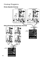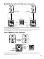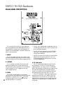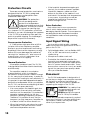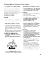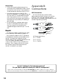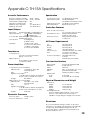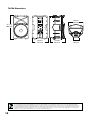
1
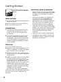
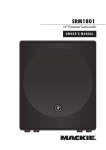
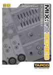
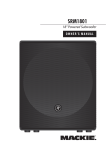
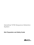
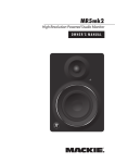
5)"
owner’s manual
CAUTION
AVIS
RISK OF ELECTRIC SHOCK
DO NOT OPEN
RISQUE DE CHOC ELECTRIQUE
NE PAS OUVRIR
CAUTION: TO REDUCE THE RISK OF ELECTRIC SHOCK
DO NOT REMOVE COVER (OR BACK)
NO USER-SERVICEABLE PARTS INSIDE
REFER SERVICING TO QUALIFIED PERSONNEL
ATTENTION: POUR EVITER LES RISQUES DE CHOC
ELECTRIQUE, NE PAS ENLEVER LE COUVERCLE. AUCUN
ENTRETIEN DE PIECES INTERIEURES PAR L'USAGER. CONFIER
L'ENTRETIEN AU PERSONNEL QUALIFIE.
AVIS: POUR EVITER LES RISQUES D'INCENDIE OU
D'ELECTROCUTION, N'EXPOSEZ PAS CET ARTICLE
A LA PLUIE OU A L'HUMIDITE
The lightning flash with arrowhead symbol within an equilateral
triangle is intended to alert the user to the presence of uninsulated
“dangerous voltage” within the product’s enclosure that may be
of sufficient magnitude to constitute a risk of electric shock to persons.
Le symbole éclair avec point de flèche à l'intérieur d'un triangle
équilatéral est utilisé pour alerter l'utilisateur de la présence à
l'intérieur du coffret de “voltage dangereux” non isolé d'ampleur
suffisante pour constituer un risque d'éléctrocution.
The exclamation point within an equilateral triangle is intended to
alert the user of the presence of important operating and maintenance
(servicing) instructions in the literature accompanying the appliance.
Le point d'exclamation à l'intérieur d'un triangle équilatéral est
employé pour alerter les utilisateurs de la présence d'instructions
importantes pour le fonctionnement et l'entretien (service) dans le
livret d'instruction accompagnant l'appareil.
SAFETY INSTRUCTIONS
1. 2. 3. 4. 5. 6. 7. Read these instructions.
Keep these instructions.
Heed all warnings.
Follow all instructions.
Do not use this apparatus near water.
Clean only with a dry cloth.
Do not block any ventilation openings. Install in accordance
with the manufacturer’s instructions.
8. Do not install near any heat sources such as radiators, heat
registers, stoves, or other apparatus (including amplifiers) that
produce heat.
9. Do not defeat the safety purpose of the polarized or
grounding-type plug. A polarized plug has two blades with
one wider than the other. A grounding-type plug has two
blades and a third grounding prong. The wide blade or
the third prong are provided for your safety. If the provided
plug does not fit into your outlet, consult an electrician for
replacement of the obsolete outlet.
10. Protect the power cord from being walked on or pinched
particularly at plugs, convenience receptacles, and the point
where they exit from the apparatus.
11. Only use attachments/accessories specified by the
manufacturer.
12. Use only with a cart, stand, tripod, bracket, or table specified
by the manufacturer, or sold with the apparatus. When a
cart is used, use caution when moving the cart/apparatus
combination to avoid injury from tip-over.
13. Unplug this apparatus during lightning storms or when unused
for long periods of time.
14. Refer all servicing to qualified service personnel. Servicing
is required when the apparatus has been damaged in any
way, such as when the power-supply cord or plug has been
damaged, liquid has been spilled or objects have fallen into
the apparatus, the apparatus has been exposed to rain or
moisture, does not operate normally, or has been dropped.
PORTABLE CART WARNING
Carts and stands - The
Component should be used
only with a cart or stand
that is recommended by
the manufacturer.
A Component and cart
combination should be
moved with care. Quick
stops, excessive force, and
uneven surfaces may cause
the Component and cart
combination to overturn.
15. This apparatus shall not be exposed to dripping or splashing,
and no object filled with liquids, such as vases, shall be
placed on the apparatus.
16. This apparatus has been designed with Class-I construction
and must be connected to a mains socket outlet with a
protective earthing connection (the third grounding prong).
17. The MAINS plug or an appliance coupler is used as the
disconnect device, so the disconnect device shall remain
readily operable.
18. This apparatus has been equipped with a double-pole AC
mains power switch. This switch is located on the rear panel
and should remain readily accessible to the user.
19. NOTE: This equipment has been tested and found to comply
with the limits for a Class B digital device, pursuant to part
15 of the FCC Rules. These limits are designed to provide
reasonable protection against harmful interference in a
residential installation. This equipment generates, uses, and
can radiate radio frequency energy and, if not installed and
used in accordance with the instructions, may cause harmful
interference to radio communications. However, there is no
guarantee that interference will not occur in a particular
installation. If this equipment does cause harmful interference
to radio or television reception, which can be determined by
turning the equipment off and on, the user is encouraged to
try to correct the interference by one or more of the following
measures:
• Reorient or relocate the receiving antenna.
• Increase the separation between the equipment and
the receiver.
• Connect the equipment into an outlet on a circuit
different from that to which the receiver is connected.
• Consult the dealer or an experienced radio/TV
technician for help.
CAUTION: Changes or modifications to this device not
expressly approved by LOUD Technologies Inc. could void the
user's authority to operate the equipment under FCC rules.
20. This apparatus does not exceed the Class A/Class B
(whichever is applicable) limits for radio noise emissions
from digital apparatus as set out in the radio interference
regulations of the Canadian Department of Communications.
ATTENTION —Le présent appareil numérique n’émet pas de bruits
radioélectriques dépassant las limites applicables aux appareils numériques
de class A/de class B (selon le cas) prescrites dans le règlement sur le
brouillage radioélectrique édicté par les ministere des communications du
Canada.
21. Exposure to extremely high noise levels may cause permanent
hearing loss. Individuals vary considerably in susceptibility to
noise-induced hearing loss, but nearly everyone will lose some
hearing if exposed to sufficiently intense noise for a period of
time. The U.S. Government’s Occupational Safety and Health
Administration (OSHA) has specified the permissible noise level
exposures shown in the following chart.
According to OSHA, any exposure in excess of these
permissible limits could result in some hearing loss. To ensure
against potentially dangerous exposure to high sound
pressure levels, it is recommended that all persons exposed to
equipment capable of producing high sound pressure levels
use hearing protectors while the equipment is in operation.
Ear plugs or protectors in the ear canals or over the ears must
be worn when operating the equipment in order to prevent
permanent hearing loss if exposure is in excess of the limits set
forth here:
Duration Per Day Sound Level dBA,
In Hours
Slow Response
8
6
4
3
2
1.5
1
0.5 0.25 or less
Typical
Example
90
Packed garage concert
92
95
VW Bus Peace Train
97
100
Cranked psychedelic tunes
102
105
High speed chase on C.H.I.P.s
110
Loudest parts at a Heavy Metal concert
115
WARNING — To reduce the risk of fire
or electric shock, do not expose this
appliance to rain or moisture.
Contents
SAFETY INSTRUCTIONS................................................2
Introduction................................................................5
Hookup Diagrams......................................................6
TAPCO TH-15A Features ...........................................8
REAR PANEL DESCRIPTION........................................8
1. INPUT.............................................................8
2. OUTPUT . .......................................................8
3. LEVEL ............................................................8
4. OL Indicator.................................................8
5. HIGH EQ........................................................9
6. MID EQ..........................................................9
7. MID FREQ......................................................9
8. LOW EQ.........................................................9
9. DIRECT/EQ Switch . .....................................9
10. POWER Switch..............................................9
11. Line Cord Socket and Fuse........................9
Protection Circuits...................................................10
Input Signal Wiring...................................................10
Placement................................................................10
Appendix A: Service Information...........................11
Appendix B: Connections .....................................12
Appendix C: TH-15A Specifications.......................13
TAPCO LIMITED WARRANTY.....................................15
Don’t forget to visit our website at www.tapcoworld.com
for more information about this and other TAPCO products.
What me, read a manual?
Before you begin, please make sure you read the Safety Instructions on page 2 and
Getting Started on page 4.
Your new TAPCO® TH-15A active loudspeakers are designed to set up quickly and
operate easily. We know it’s often seen as a sign of weakness to read a manual, along with
asking for directions when lost, but we hope you will read the rest of the manual, at least
while nobody is looking.
It is important to keep your receipt in a safe place, and not a bad idea to write your
product information here for future reference (i.e., insurance claims, tech support, return
authorization, etc.).
Product Serial #:
Purchased at:
Date of purchase:
Part No. SW0621 Rev. E 08/08
©2006-2008 LOUD Technologies Inc. All Rights Reserved.
Getting Started
The following steps will help
you set up your loudspeakers
quickly.
INITIAL SETTINGS:
1. Turn the LEVEL control on the rear panel
all the way down.
2. Set the DIRECT/EQ switch out (DIRECT).
3. Turn the POWER switch OFF.
CONNECTIONS:
1. Connect the line-level signal from your
mixer (or other signal source) to the
IN jack on the TH-15A rear panel (XLR
connector).
2. Connect the supplied AC power cord
to the IEC socket on the back of the
loudspeaker. Plug the other end into an
AC outlet properly configured with the
correct voltage as indicated just below
the IEC socket.
TURN IT ON:
1. Turn the POWER switch ON.
2. Start your signal source (tape deck, CD,
DAW, or whatever), but leave the master
level control on your mixer down.
3. Slowly turn up the LEVEL control on the
TH-15A to the “U” (unity gain) mark at the
center position.
4. Adjust the master volume on your mixer
to a comfortably loud listening level. If
the volume from the speakers gets really
loud, really fast, try turning down the
LEVEL control on the TH-15As a bit. If the
speakers don’t get loud enough, turn
up the LEVEL control to achieve a good
balance of master volume control and
loudness from the speaker.
Now that you have your loudspeakers
working, it’s time to hunker down and read
the rest of this manual…especially the
following:
ADDITIONAL TIDBITS OF WIDSDOM:
• Never listen to loud music for prolonged
periods. Please see the Safety Instructions
on page 2 for information on hearing
protection.
• When you shut down your equipment,
turn off the TH-15A loudspeakers first
to prevent thumps and other noises
generated by any upstream equipment
from coming out the speakers. When
powering up, turn on the TH-15As last.
• Save the shipping boxes and packing
materials! You may need them someday.
Besides, your cat will love playing in them
and jumping out at you unexpectedly.
Remember to pretend like you are
surprised!
• Save your sales receipt in a safe place.
• Record the serial number in the space
provided on page 3, along with where
and when you bought it.
Introduction
Thank you for choosing the TAPCO TH-15A active loudspeakers. The TAPCO product
line hails back to the days of TAPCO Corporation, Greg Mackie’s first company. TAPCO
revolutionized the audio industry back in 1969 with the very first 6-channel mixer specifically
designed for keyboards and rock ‘n’ roll. In essence, TAPCO redefined the price/
performance ratio and made high-quality professional audio equipment accessible to
virtually anyone. Today, TAPCO shares the same ideals, and is backed by the world-class
engineering and manufacturing horsepower of LOUD Technologies.
The TH-15A active loudspeakers are packed with features and designed to produce
transparent and uncolored sound for PA systems and sound reinforcement. The two-way
bass reflex (ported) design provides an amazingly flat frequency response from 40 Hz to
20 kHz. These versatile compact loudspeakers can be used in a variety of applications,
and when combined with the TAPCO TH-18s active subwoofers, they form an amazing
system. The durable, lightweight enclosure is designed with a socket in the bottom for polemounting on a stand or with the TAPCO TH-18s. In addition, the TH-15A loudspeakers can be
placed on their side for use as floor monitors.
There are many benefits to integrating an active crossover, power amplifiers, and drivers
into a single cabinet, and we’ve taken full advantage of these benefits in the design of the
TH-15A.
• The crossover point is designed so that the high and low-frequency drivers are fed only
the frequencies that they are best able to reproduce.
• The amplifiers are designed to provide maximum acoustic output from the speakers, yet
minimize the danger of speaker damage due to overdriving.
• The length of the connecting wires between the amplifier outputs and the drivers are
kept to an absolute minimum so the damping factor of the amplifier isn’t compromised
by the resistance of long speaker cables.
• The acoustic sum of the outputs from the two drivers are optimized electronically, as well
as physically, so the amplitude response is unity and the phase difference is minimal.
In short, all the complex interconnected components in the system are designed to work
in harmony with each other to produce the best possible sound.
Here’s a quick look at all the features packed into the TH-15A loudspeakers:
• Flat frequency response (–10 dB, 40 Hz to
20 kHz)
• Balanced Mic/Line XLR input and thru
connectors
• 1” high-frequency compression driver
• 24 dB/octave crossover at 3 kHz
• 15” low-frequency woofer
• Adjustable input level control
• Convenient portable design, with
integrated handles in both sides and top
• LF equalization provides ±15 dB at 80 Hz
and below
• Ported, bass reflex design for enhanced
bass performance
• MF equalization provides ±15 dB with
sweepable frequency from 100 Hz to 8 kHz
• 99 watt HF and 298 watt LF power
amplifiers (peak)
• Low-frequency over-excursion protection
• HF equalization provides ±15 dB at 12 kHz
and above
• High-strength lightweight cabinet
constructed of polypropylene
• EQ bypass (DIRECT) switch
• High-density adiabatic fiberfill absorbs
internal reflections
• Pole-mount socket
• Rear panel power switch
Hookup Diagrams
Stereo Speaker Hookup
TH-15A ACTIVE LOUDSPEAKER
TH-15A ACTIVE LOUDSPEAKER
EQ
U
EQ
U
HIGH
12kHz
-15
HIGH
12kHz
DIRECT
EQ
+15
-15
MID
FREQ
100
POWER
-15
U
MID
FREQ
8k
U
100
POWER
OL
MID
LEVEL
+15
-15
U
LOW
80Hz
O
-15
8k
U
OL
MID
LEVEL
+15
U
U
LOW
80Hz
O
+15
OUT
DIRECT
EQ
+15
-15
MAX
IN
+15
MAX
OUT
IN
Daisy-Chaining Two Speakers Per Side
TH-15A
Left
Line-Level
Output
TH-15A
EQ
EQ
U
U
HIGH
12kHz
-15
HIGH
12kHz
DIRECT
EQ
+15
-15
+15
MID
FREQ
100
POWER
-15
MID
FREQ
8k
U
U
100
POWER
OL
MID
LEVEL
+15
-15
U
LOW
80Hz
O
-15
DIRECT
EQ
Right
Line-Level
Output
U
U
8k
+15
1
-15
MAX
1
1
MAX
IN
L
L
(MON0)
2
Mixer or
Preamplifier
MIC
INPUT
MIC
INPUT
MIC
INPUT
MIC
INPUT
BAL/UNBAL
BAL/UNBAL
BAL/UNBAL
BAL/UNBAL
AUX SEND
AUX RETURN
(MONO)
LINE
LINE
LINE
BAL
OR
UNBAL
R
0
GAIN
75Hz
EQ
U
0
GAIN
75Hz
2
EQ
U
HIGH
ECHO
SPRING
STAGE
-15
U
+15
75Hz
EQ
U
HIGH
12kHz
U
+15
75Hz
EQ
U
HIGH
12kHz
-15
GAIN
4
U
+15
+4
-10
5
6
EQ
U
HIGH
12kHz
-15
LINE
U
+15
U
HIGH
12kHz
-15
7
8
U
+15
FLANGER
ROTARY
-15
U
13
STUDIO
12
16
1
9
8
2
3
4
5
11
CHORUS+REV
6
10
HALL
FX
INPUT
LEVEL
12kHz
CATHEDRAL
CHORUS
THEATER
HIGH
12kHz
-15
+4
-10
EQ
14
STEREO DELAY
FLANGER+REV
LINE
15
ECHO+REV
ROOM
0
GAIN
3
FOOTSW
INTERNAL EFFECTS
R
TREMOLD
0
PHANTOM
48V
OUT
CD/TAPE
INPUT/OUTPUT
L
BAL
OR
UNBAL
LINE
R
IN
FX RETURN
(MONO)
L
1
POWER
PHONES
R
R
FX
+15
OUT
L
1
MON
U
80Hz
IN
1
LEVEL
LOW
O
OUT
OL
MID
+15
7
VARIATIONS
FX
BYPASS
FX OL
+15
MAX
CONTROL ROOM
MID
MID
2.5kHz
-15
+15
+15
+15
MON
TH-15A
L
R
L
MUTE
HIGH
12kHz
-15
10
HIGH
U
12kHz
-15
DIRECT
EQ
-15
U
100
POWER
OL
MID
LEVEL
+15
-15
U
LOW
O
80Hz
-15
+15
IN
Left
Line-Level
Output
1
1
1
Right
Line-Level
Output
L
1
L
L
MON
(MON0)
2
MIC
INPUT
MIC
INPUT
MIC
INPUT
BAL/UNBAL
BAL/UNBAL
BAL/UNBAL
AUX SEND
AUX RETURN
(MONO)
LINE
LINE
LINE
BAL
OR
UNBAL
R
0
GAIN
75Hz
EQ
U
0
GAIN
75Hz
2
EQ
U
HIGH
ECHO
SPRING
STAGE
-15
U
+15
75Hz
EQ
U
HIGH
12kHz
U
+15
75Hz
EQ
U
HIGH
12kHz
-15
GAIN
4
U
+15
+4
-10
5
6
EQ
U
HIGH
12kHz
-15
LINE
U
+15
U
HIGH
12kHz
-15
7
8
U
+15
FLANGER
ROTARY
-15
U
13
STUDIO
12
16
1
9
8
2
3
4
5
11
CHORUS+REV
6
10
HALL
FX
INPUT
LEVEL
12kHz
CATHEDRAL
CHORUS
THEATER
HIGH
12kHz
-15
+4
-10
EQ
14
STEREO DELAY
FLANGER+REV
LINE
15
ECHO+REV
ROOM
0
GAIN
3
FOOTSW
INTERNAL EFFECTS
R
TREMOLD
0
PHANTOM
48V
OUT
CD/TAPE
INPUT/OUTPUT
L
BAL
OR
UNBAL
LINE
R
IN
FX RETURN
(MONO)
L
1
POWER
PHONES
R
R
FX
MIC
INPUT
BAL/UNBAL
7
VARIATIONS
FX
BYPASS
FX OL
+15
MAX
CONTROL ROOM
MID
MID
2.5kHz
-15
+15
+15
+15
MON
R
L
MUTE
R
OL
10
OL
L
U
SOLO
R
10
OL
L
U
SOLO
OL
R
U
SOLO
+15
FX
+2
0
RTRN
TO
AUX 1
SOLO
L
R
-2
-5
+15
+15
3
7
8
-20
0dB = 0dBu
ALT
MUTE
LEVEL
SET
+5
MAIN
ALT 3-4
RETURN
2
FX
+15
BAL
ALT
4
MAIN
MIX
ALT
3/4
dB
10
5
SOLO
MON
+15
+10
U
2
FX
+15
5
6
10
SOLO
MODE
RUDE SOLO
PRE
2
ALT
3/4
dB
5
AUX
RETURN
1
+15
U
PRE
BAL
MUTE
4
ALT
3/4
dB
5
TAPE TO
MAIN
MAX
CTRL ROOM/
PHONES
CLIP
FX
+15
MUTE
3
ALT
3/4
dB
5
U
R
MUTE
2
ALT
3/4
10
ALT
3-4
MASTER
AUX SEND
U
MON
+15
2
PAN
CD/
TAPE
SOURCE SELECT
1
U
PRE
FX
+15
MAIN
MIX
AUX
SEND
MON
+15
2
PAN
L
MUTE
1
ALT
3/4
80Hz
+15
U
1
U
PRE
FX
+15
LOW
-15
AUX
SEND
MON
+15
2
PAN
PFL
AFL
+15
U
80Hz
+15
U
1
U
PRE
FX
+15
2.5kHz
-15
LOW
-15
AUX
SEND
MON
+15
2
PAN
+15
U
80Hz
+15
U
1
U
PRE
FX
+15
MID
2.5kHz
-15
LOW
-15
AUX
SEND
MON
+15
dB
+15
U
1
U
+15
U
80Hz
-15
AUX
SEND
U
MID
2.5kHz
-15
LOW
80Hz
-15
1
L
+15
U
LOW
80Hz
AUX
SEND
MID
2.5kHz
-15
U
LOW
+15
U
OL
dB
10
5
U
SOLO
OL
U
SOLO
dB
dB
5
5
10
5
10
U
SOLO
dB
10
5
U
U
dB
10
5
U
5
5
5
5
5
5
5
5
5
5
10
10
10
10
10
10
10
10
10
10
OO
MID
2.5kHz
-15
U
-15
20
20
20
20
20
20
20
20
20
20
30
30
30
30
30
30
30
30
30
30
40
50
60
OO
40
50
60
OO
40
50
60
OO
40
50
60
OO
40
50
60
OO
40
50
60
OO
40
50
60
40
50
60
OO
40
50
60
OO
40
50
60
OO
LEVEL
+15
U
LOW
+15
OUT
Thru
OL
MID
80Hz
-15
MAX
Thru
1
U
8k
O
OUT
Mixer or
Preamplifier
U
MAX
IN
R
L
U
SOLO
R
10
OL
U
SOLO
R
OL
L
U
R
+2
0
-2
-5
+15
+15
-20
0dB = 0dBu
ALT
3
7
8
LEVEL
SET
+5
MAIN
ALT 3-4
RTRN
TO
AUX 1
SOLO
ALT
4
MAIN
MIX
ALT
3/4
dB
10
5
SOLO
+15
FX
RETURN
2
FX
+15
BAL
MUTE
5
6
10
SOLO
U
2
FX
+15
ALT
3/4
dB
5
+10
PRE
2
MUTE
4
ALT
3/4
dB
MON
+15
+15
U
PRE
BAL
L
MUTE
3
OL
5
CLIP
FX
+15
SOLO
MODE
RUDE SOLO
OL
dB
10
5
U
SOLO
OL
U
SOLO
dB
dB
5
5
10
5
10
U
SOLO
dB
10
5
U
U
dB
10
5
U
5
5
5
5
5
5
5
5
5
10
10
10
10
10
10
10
10
10
MID
FREQ
8k
U
10
AUX
RETURN
5
OO
100
L
ALT
3/4
dB
TAPE TO
MAIN
MAX
CTRL ROOM/
PHONES
1
10
+15
MID
FREQ
POWER
OL
ALT
3-4
MASTER
AUX SEND
U
MON
+15
2
PAN
CD/
TAPE
SOURCE SELECT
1
U
PRE
FX
+15
MAIN
MIX
AUX
SEND
MON
+15
2
PAN
MUTE
2
ALT
3/4
dB
5
DIRECT
EQ
+15
R
MUTE
1
ALT
3/4
EQ
U
80Hz
+15
U
1
U
PRE
FX
+15
LOW
-15
AUX
SEND
MON
+15
2
PAN
PFL
AFL
+15
U
80Hz
+15
U
1
U
PRE
FX
+15
2.5kHz
-15
LOW
-15
AUX
SEND
MON
+15
2
PAN
+15
U
80Hz
+15
U
1
U
PRE
FX
+15
MID
2.5kHz
-15
LOW
-15
AUX
SEND
MON
+15
EQ
+15
U
1
U
+15
U
80Hz
-15
AUX
SEND
U
MID
2.5kHz
-15
LOW
80Hz
-15
1
U
+15
U
LOW
80Hz
AUX
SEND
MID
2.5kHz
-15
U
LOW
+15
U
TH-15A
MID
2.5kHz
-15
U
-15
20
20
20
20
20
20
20
20
20
20
30
30
30
30
30
30
30
30
30
30
40
50
60
OO
40
50
60
OO
40
50
60
OO
40
50
60
OO
40
50
60
OO
40
50
60
OO
40
50
60
40
50
60
OO
40
50
60
OO
40
50
60
OO
Main PA System with two TH-18s active subwoofers
TH-15A
TH-15A
ACTIVE SOUND
REINFORCEMENT LOUDSPEAKER
ACTIVE SOUND
REINFORCEMENT LOUDSPEAKER
EQ
EQ
HIGH
HIGH
12kHz
-15
100
POWER
-15
12kHz
DIRECT
EQ
+15
U
U
-15
8k
100
POWER
OL
MID
LEVEL
+15
-15
U
LOW
80Hz
O
-15
U
8k
LEVEL
U
LOW
+15
MAX
OUT
IN
Left Main
Powered Loudspeaker
(TAPCO TH-15A)
Right Main
Powered Loudspeaker
(TAPCO TH-15A)
Full-Range
Output
Mixing Console
(TAPCO MIX260FX shown)
Pole Mount
Pole Mount
OL
U
MAX
L
L
R
R
R
SERIAL NUMBER
WARNING: TO REDUCE THE RISK OF FIRE OR ELECTRIC
SHOCK, DO NOT EXPOSE THIS EQUIPMENT TO RAIN OR
MOISTURE. DO NOT REMOVE COVER. NO USER SERVICEABLE
PARTS INSIDE. REFER SERVICING TO QUALIFIED PERSONNEL.
AVIS: RISQUE DE CHOC ELECTRIQUE — NE PAS OUVRIR
POLARITY
ACTIVE SOUND
REINFORCEMENT SUBWOOFER
NORMAL
REV 180
L
DESIGNED IN WOODINVILLE, WA, USA • MANUFACTURED IN CHINA •
FABRIQUE EN CHINE • COPYRIGHT ©2007 •
THE FOLLOWING ARE TRADEMARKS OR REGISTERED TRADEMARKS
OF LOUD TECH. INC.: "TAPCO" • PATENT PENDING
OL
U
MAX
POLARITY
ACTIVE SOUND
REINFORCEMENT SUBWOOFER
OL
MID
+15
80Hz
-15
MAX
IN
Full-Range
Output
DIRECT
EQ
+15
U
O
+15
OUT
From Mixer
Right Output
1
2
3
4
5
6
7
8
9
10
11
12
SUB
1
SUB
2
MAIN
MIX
From Mixer
Left Output
THIS DEVICE COMPLIES WITH PART 15 OF THE FCC RULES FOR THE
U.S. AND ICES-003, FOR CANADA. OPERATION IS SUBJECT TO THE
FOLLOWING TWO CONDITIONS: (1) THIS DEVICE MAY NOT CAUSE
HARMFUL INTERFERENCE, AND
(2) THIS DEVICE MUST ACCEPT ANY INTERFERENCE RECEIVED,
INCLUDING INTERFERENCE THAT MAY CAUSE UNDESIRED OPERATION.
L
L
R
R
R
DESIGNED IN WOODINVILLE, WA, USA • MANUFACTURED IN CHINA •
FABRIQUE EN CHINE • COPYRIGHT ©2007 •
THE FOLLOWING ARE TRADEMARKS OR REGISTERED TRADEMARKS
OF LOUD TECH. INC.: "TAPCO" • PATENT PENDING
MANUFACTURING DATE
SERIAL NUMBER
POWER
Active Subwoofer
(TAPCO TH-18s)
FUSE: T10A AC250V
NORMAL
REV 180
L
WARNING: TO REDUCE THE RISK OF FIRE OR ELECTRIC
SHOCK, DO NOT EXPOSE THIS EQUIPMENT TO RAIN OR
MOISTURE. DO NOT REMOVE COVER. NO USER SERVICEABLE
PARTS INSIDE. REFER SERVICING TO QUALIFIED PERSONNEL.
AVIS: RISQUE DE CHOC ELECTRIQUE — NE PAS OUVRIR
THIS DEVICE COMPLIES WITH PART 15 OF THE FCC RULES FOR THE
U.S. AND ICES-003, FOR CANADA. OPERATION IS SUBJECT TO THE
FOLLOWING TWO CONDITIONS: (1) THIS DEVICE MAY NOT CAUSE
HARMFUL INTERFERENCE, AND
(2) THIS DEVICE MUST ACCEPT ANY INTERFERENCE RECEIVED,
INCLUDING INTERFERENCE THAT MAY CAUSE UNDESIRED OPERATION.
MANUFACTURING DATE
POWER
Active Subwoofer
(TAPCO TH-18s)
FUSE: T10A AC250V
The left and right line-level outputs from a mixer feed the inputs of two TAPCO TH-18s subwoofers. The full-range
line-level outputs of the subwoofers feed the inputs of the TH-15A loudspeakers, so these play the full range in
stereo, and the subs provide bass reinforcement.
Alternatively, you can use the high-pass line-level outputs of the subwoofers to feed the loudspeakers, then the
subs will handle all the lows, while the TH-15A loudspeakers handle the mids and highs.
Using one TH-18s active subwoofer
TH-15A
TH-15A
ACTIVE SOUND
REINFORCEMENT LOUDSPEAKER
ACTIVE SOUND
REINFORCEMENT LOUDSPEAKER
EQ
HIGH
12kHz
-15
100
POWER
-15
DIRECT
EQ
+15
U
U
8k
OL
MID
LEVEL
+15
U
LOW
80Hz
O
-15
+15
OUT
MAX
IN
Left and Right Main
Powered Loudspeakers
(TAPCO TH-15A)
EQ
HIGH
12kHz
-15
100
POWER
-15
DIRECT
EQ
+15
U
U
8k
OL
MID
LEVEL
+15
U
LOW
80Hz
O
-15
+15
OUT
MAX
IN
OL
U
MAX
POLARITY
ACTIVE SOUND
REINFORCEMENT SUBWOOFER
Full-Range
Output
L
L
R
R
R
DESIGNED IN WOODINVILLE, WA, USA • MANUFACTURED IN CHINA •
FABRIQUE EN CHINE • COPYRIGHT ©2007 •
THE FOLLOWING ARE TRADEMARKS OR REGISTERED TRADEMARKS
OF LOUD TECH. INC.: "TAPCO" • PATENT PENDING
SERIAL NUMBER
POWER
Active Subwoofer
(TAPCO TH-18s)
FUSE: T10A AC250V
NORMAL
REV 180
L
WARNING: TO REDUCE THE RISK OF FIRE OR ELECTRIC
SHOCK, DO NOT EXPOSE THIS EQUIPMENT TO RAIN OR
MOISTURE. DO NOT REMOVE COVER. NO USER SERVICEABLE
PARTS INSIDE. REFER SERVICING TO QUALIFIED PERSONNEL.
AVIS: RISQUE DE CHOC ELECTRIQUE — NE PAS OUVRIR
From Mixer
Left and Right
Outputs
1
2
3
4
5
6
7
8
9
10
11
12
SUB
1
SUB
2
MAIN
MIX
THIS DEVICE COMPLIES WITH PART 15 OF THE FCC RULES FOR THE
U.S. AND ICES-003, FOR CANADA. OPERATION IS SUBJECT TO THE
FOLLOWING TWO CONDITIONS: (1) THIS DEVICE MAY NOT CAUSE
HARMFUL INTERFERENCE, AND
(2) THIS DEVICE MUST ACCEPT ANY INTERFERENCE RECEIVED,
INCLUDING INTERFERENCE THAT MAY CAUSE UNDESIRED OPERATION.
MANUFACTURING DATE
Mixing Console
(TAPCO MIX260FX shown)
The left and right line-level outputs from a mixer feed the inputs of a TH-18s active subwoofer. The full-range linelevel outputs of the subwoofer feed the inputs of the TH-15A loudspeakers, so these play the full range in stereo,
and the sub provides bass reinforcement.
TAPCO TH-15A Features
REAR PANEL DESCRIPTION
TH-15A
ACTIVE SOUND
REINFORCEMENT LOUDSPEAKER
EQ
U
5
-15
7
100
-15
10
8
9
DIRECT
EQ
+15
MID
FREQ
POWER
O
HIGH
12kHz
U
U
8k
OL
MID
6 LEVEL
+15
LOW
80Hz
-15
+15
OUT
4
U
MAX
3
IN
11
2
This is where you connect your signal to
the loudspeaker and make adjustments to
the frequency response of the speaker to
match the loudspeaker’s location and your
room’s environment.
1. INPUT
• The TH-15A is designed to operate with a
+4 dBu signal when the LEVEL control is at
the U (center) position.
• The TH-15A can accept up to a +20 dBu
signal by turning down the INPUT LEVEL
control accordingly.
This is a female XLR-type connector that
accepts a balanced mic or line-level signal
from a mixing console or other signal source.
• NEVER connect the output of an amplifier
directly to the input of the TH-15A. This
could damage the active input circuitry
of the loudspeaker.
2. OUTPUT
4. OL Indicator
This is a male XLR-type connector that
produces exactly the same signal that is
connected to the input jack. Use it to daisychain several TH-15A’s together off the
same signal source.
The OL (overload) indicator lights when
the amplifiers in the TH-15A are near the
clipping point. It is okay if the OL indicator
blinks occasionally, because this means that
the transient peaks are just reaching the
maximum output of the amplifiers and you
are getting the most from your TH-15As.
3. LEVEL
1
The LEVEL control adjusts the overall
signal level at the input to the built-in power
amplifiers. It ranges from Off ( ) to MAX
(maximum gain), with unity gain at the
center position (12 o’clock).
If the OL indicator is blinking frequently or
lighting continuously, turn down the LEVEL
control [3] on the TH15A or turn down the
signal at it source (e.g., the mixing console)
until the OL indicator blinks occasionally or
not at all.
5. HIGH EQ
10. POWER Switch
This control gives you up to 15 dB boost
or cut above 12 kHz, and it is also flat
at the center position (U). Use it to add
sizzle to cymbals, and an overall sense of
transparency or edge to the keyboards,
vocals, guitar, and bacon frying. Turn it
down a little to reduce sibilance, or to hide
tape hiss.
Use this switch to turn the active
loudspeakers on and off. The indicating
LED above the POWER switch lights when
the POWER switch is on and AC power is
available at the linecord socket. A second
power indicator is located on the front of
the cabinet.
6. MID EQ
This is a midrange EQ control that
provides 15 dB of boost or cut centered at
any frequency between 100 Hz and 8 kHz.
The MID EQ circuit is flat (no boost or cut)
at the center position. This frequency range
includes most vocals (male at the lower end
of the range and female at the upper end
of the range), and the fundamentals and
harmonics for many instruments.
11. Line Cord Socket and Fuse
Connect the detachable line cord to
this IEC socket securely, and plug the other
end into your AC outlet. Make sure the
AC power is matched to the AC power
indicated on the rear panel (under the IEC
socket).
The fuse is located behind the fuse cover,
at the bottom of the IEC socket. See the
“Troubleshooting” section on page 9 for
information about replacing the fuse.
7. MID FREQ
This knob ranges from 100 Hz
to 8 kHz and determines the center
frequency for the MID EQ filter. This allows
you to zero in on the precise narrow band of
frequencies you want to have affected by
the MID EQ.
8. LOW EQ
This control gives you up to
15 dB of boost or cut below 80 Hz.
The circuit is flat (no boost or cut) at the
center position. This frequency range
represents the punch in bass drums, bass
guitar, fat synth patches, and some really
serious male singers.
9. DIRECT/EQ Switch
This switch allows you to bypass the EQ
section. When the switch is out (DIRECT), the
EQ section is bypassed and the EQ knobs
have no effect on the signal. When the
switch is pushed in (EQ), the EQ controls can
be used to tailor the frequency response of
the TH-15As.
Protection Circuits
There are several protection mechanisms
designed into the TH-15A to safeguard
the loudspeakers and amplifiers from
inadvertent damage.
CAUTION: The protection
circuits are designed to
protect the loudspeakers
under reasonable and sensible
conditions. Should you choose
to ignore the warning signs
(i.e., frequent OL LED indications, excessive
distortion), you can still damage the speakers
in the TH-15A by overdriving them past the
point of amplifier clipping. Such damage is
beyond the scope of the warranty.
Overexcursion Protection
A 12 dB/octave high-pass filter at 40 Hz
just prior to the low-frequency amplifier
prevents very low frequencies from being
amplified. Excessive low-frequency energy
below 40 Hz can damage the woofer by
causing it to “bottom out,” also known as
overexcursion, which is equivalent to a
mechanical form of clipping.
Thermal Protection
All amplifiers produce heat. The TH-15A
is designed to be efficient both electrically
and thermally.
The amplifier module is mounted on
a large heatsink, which is cooled by
convection where cool air is drawn through
it’s fins, carrying the heat away. In order for
this convection cooling to work efficiently, it
is important to provide adequate airspace
behind the loudspeaker. When you position
the TH-15A, we recommend leaving at least
six inches of air space behind it.
• If for some reason the heatsink gets too
hot, a built-in thermal switch activates
and turns off the amplifier. This protection
operates independently for the lowfrequency and high-frequency amplifiers.
Therefore, it is possible for only the low
frequency or high frequency amplifier to
shut down while the other remains on.
• When the heatsink cools down to a safe
temperature, the thermal switch resets
and normal operation resumes.
10
• If the heatsink temperature again gets
too hot, the shutdown process repeats.
Should this happen, make sure that
airflow to the rear of the cabinet is not
restricted. If the ambient air temperature
is very warm, try pointing a small fan
toward the heatsink to increase the
airflow through the fins.
Driver Protection
Each driver has its own compression
circuit, which helps protect them from
damaging transient peaks. The compressors
are designed to be transparent and are
not noticeable under normal operating
conditions.
Input Signal Wiring
You should use high-quality, shielded
cable to connect the signal source to the IN
jack on the TH-15A.
• Foil shielded cables, such as Belden 8451,
8761, or 9501 are commonly used for
studio wiring.
• Microphone cables work well.
• The better the shield, the better the
immunity from externally induced noise
(like EMI and RFI). Route the cable away
from AC power cords and outlets. These
are common sources for hum in an audio
signal. You can purchase quality cables
from your Mackie dealer.
Placement
The TH-15A loudspeaker is designed to sit
on the floor or stage. It can be pole-mounted
via the built-in socket on the bottom of
the cabinet. Be sure the pole is capable of
supporting the weight of the TH-15A.
WARNING: The cabinet has
no rigging points and is not
suitable for rigging.
NEVER attempt to suspend
the TH-15A by its handles.
As with any powered components, protect
them from moisture. If you are setting them
up outdoors, make sure they are under
cover if you expect rain.
Appendix A: Service Information
If you think your TAPCO product has a
problem, please check out the following
troubleshooting tips and do your best to
confirm the problem. Visit the “Talk To Us”
section of our website (www.tapcoworld.
com) to contact our technical support
heroes and get some ideas. You may find
the answer to the problem without having
to send your TAPCO product away.
Troubleshooting
No Power
• Our favorite question: Is it plugged in?
• Make sure the line cord is securely seated
in the line cord socket and plugged all
the way into the AC outlet.
• Make sure the AC outlet is live (check
with a tester or lamp).
• Is the POWER switch in the ON position?
• Are the power LEDs on the front and rear
panel illuminated? If not, make sure the
AC outlet is live. If so, refer to “No Sound”
below.
• If the power LEDs are not illuminated, and
you are certain that the AC outlet is live,
it is possible the fuse has blown.
To remove and replace the fuse:
1. Disconnect the power cord from the
IEC socket.
2. Remove the fuse drawer by prying it
open with a small screwdriver. It will slide
all the way out.
FUSE
3. Remove the fuse and replace it with
an equivalent-type fuse.
115 VAC unit: 6 amp slo-blo (T6AL/250 V)
230 VAC unit: 3.15 amp slo-blo (T3.15AL/250 V)
4. Replace the fuse drawer by pushing it
all the way back into the IEC socket.
If two fuses blow in a row, then something
is very wrong. See the “Repair” section on
the next page to find out what to do.
No Sound
• Are the power LEDs on the front and rear
panel illuminated?
• Is the LEVEL control turned up?
• Is the signal source turned up? Make sure
the signal level from the mixing console
(or whatever device immediately
precedes the loudspeaker) is high
enough to produce sound.
• If it’s a stereo pair, try switching them
around. For example, if a left speaker is
presumed dead, switch the left and right
cords at the speakers. If the problem
switches sides, it’s not the TH-15A. It could
be a bad cable, or no signal from the
mixer.
Bad Sound
• Is the input connector plugged
completely into the IN jack?
• Is something connected to the OUT jack?
Try unplugging it. If the sound improves,
whatever was plugged into the OUT jack
may have affected the signal.
• Is it loud and distorted? Reduce the signal
level at the mixer.
• If possible, listen to the signal source with
headphones plugged into the preamp
stage. If it sounds bad there, it’s not the
loudspeaker.
• Too much bass or not enough bass?
Move around the room and see if the
bass response changes. It’s possible your
listening position coincides with a room
mode where the low frequencies either
become exaggerated or nulled. If so, try
moving the loudspeakers to a different
position, or moving your listening position.
11
Noise/Hum
• Check the signal cable between the
mixer and the loudspeaker. Make sure all
connections are secure. These problems
usually produce crackling noises or hum.
• If you are using two or more TH-15A
active loudspeakers, try plugging them all
into the same AC outlet panel or outlet
strip. The purpose for this is to connect
them all to the same earth ground point
and reduce the possibility of creating a
ground loop.
Appendix B:
Connections
XLR Connectors
XLR connectors are used to make
balanced input and through connections
to the TH-15A. They are wired as follows,
according to standards specified by the AES
(Audio Engineering Society).
2
SHIELD
• If connecting an unbalanced output
to the TH-15A balanced input, make
sure the shield is connected to the
unbalanced ground and to pin 1 of the
XLR.
HOT
COLD
SHIELD
COLD 3
HOT
Repair
1
3
1
2
1
For warranty repair or replacement, refer
to the warranty information on page 15.
Non-warranty repair for TAPCO products
is available at a factory-authorized service
center. To locate your nearest service
center, call our Tech Support department at
1-877-827-2669, Monday-Friday,
7 am to 5 pm Pacific Time, to explain the
problem. Tech Support will tell you where
the nearest factory-authorized service
center is located in your area.
3
COLD
2
XLR Balanced Wiring
Pin 1 = Shield
Pin 2 = Hot (+)
Pin 3 = Cold (–)
SHIELD
HOT
Lonely? Looking for that special someone?
Do you have a question about your TAPCO loudspeaker?
Please call our Technical Support chaps at 1-877-827-2669, Monday to Friday, from 7 AM to 5 PM PST.
After hours, visit www.tapcoworld.com and look under Talk To Us, or e-mail us at [email protected]
12
Appendix C: TH-15A Specifications
Acoustic Performance
Frequency Range (–10 dB): Frequency Response (–3 dB): Horizontal Coverage Angle:
Vertical Coverage Angle:
Maximum SPL Long-Term: Maximum SPL Peak:
Equalization
40 Hz – 20 kHz
50 Hz – 18.5 kHz
90º
60º
113 dB SPL @ 1m
116 dB SPL @ 1m
Input/Output
Input Type: Female XLR Balanced/Unbalanced
Input Impedance: 20 k balanced bridging;
10 k unbalanced
Loop-through:Male XLR Balanced/Unbalanced
(parallel with input)
Level Control:
Rotating knob
0 dB at center
Sensitivity:
+4 dBu for full output
(Level Control @ Center)
–36 dBu for full output
(Level Control @ Max)
Transducers
Low Frequency:
15 in/381 mm with steel frame,
paper cone woofer
High Frequency:
Horn-loaded 1 in/25 mm exit
compression driver
Power Amplifiers
Low Frequency Power Amplifier
Rated Power:
150 watts, 8 ohm load
298 watts peak
THD:
<0.1%
Signal-to-Noise Ratio:
> –94 dB, 20 Hz to 20 kHz, unweighted,
referenced to 138 watts into 8 ohms
Design:
BTL Class D
High Frequency Power Amplifier
Rated Power:
50 watts, 4 ohm load
99 watts peak
THD:
<0.1 %
Signal-to-Noise Ratio:
> –97 dB, 20 Hz to 20 kHz, unweighted,
referenced to 50 watts into 4 ohms
Design:
Class AB
Electronic Crossover
Crossover Type: 24 dB/octave
Crossover Frequency: 3 kHz
Low Frequency EQ: Mid Frequency EQ:
High Frequency EQ: Direct/EQ Switch:
±15 dB @ 80 Hz, shelving
±15 dB, bandpass,
sweepable from100 Hz to 8 kHz
±15 dB @ 12 kHz, shelving
Bypasses EQ section
Protection Features
Over-excursion Protection:
Second-order sub-sonic filter
Thermal Protection:
Independent amplifier shutdown, auto reset
Driver Protection:
Independent HF and LF compressors
AC Power Requirements
US: Europe: Korea: Japan: AC Connector: Fuse:
Power Consumption:
120 VAC, 60 Hz
240 VAC, 50 Hz
220 VAC, 60 Hz
100 VAC, 50/60 Hz
3-pin IEC 250 VAC, 20 A male
115 VAC: T 6 AL/250 V
230 VAC: T 3.15 AL/250 V
320 watts with music,
loud mix
20 watts quiescent (idle)
Construction Features
Basic Design:
Material:
Finish:
Handles:
Grille:
Display LEDs
Front:
Rear:
Asymmetrical Trapezoidal
Polypropylene
Textured
One on each side, one on top
Perforated metal with weather-resistant coating
Power ON
Power ON, OL (overload)
Physical Dimensions and Weight
Dimensions
Height: 27.1 in/689 mm
Width: 16.8 in/427 mm
Depth: 15.8 in/401 mm
Weight: 36 lb/16.3 kg
Mounting Methods:
Pole-mountable via the built-in socket on the bottom of the cabinet. Be sure the pole is capable of supporting the weight of the TH-15A.
Disclaimer
Since we are always striving to make our products
better by incorporating new and improved materials,
components, and manufacturing methods, we
reserve the right to change these specifications at
any time without notice.
13
TH-15A Dimensions
16.8 in/
427 mm
27.1 in/
689 mm
O
16.8 in/
427 mm
15.8 in/
401 mm
6.1 in/
155 mm
Correct Disposal of this product: This symbol indicates that this product should not be disposed of with your household waste, according to the WEEE
Directive (2002/96/EC) and your national law. This product should be handed over to an authorized collection site for recycling waste electrical and
electronic equipment (EEE). Improper handling of this type of waste could have a possible negative impact on the environment and human health due
to potentially hazardous substances that are generally associated with EEE. At the same time, your cooperation in the correct disposal of this product will
contribute to the effective usage of natural resources. For more information about where you can drop off your waste equipment for recycling, please
contact your local city office, waste authority, or your household waste disposal service.
14
TAPCO LIMITED WARRANTY
A. LOUD Technologies Inc. warrants all materials, workmanship
and proper operation of this product for a period of one
year from the original date of purchase. You may purchase
an additional 24-month Extended Warranty (for a total of
36 months of coverage). Visit our website and follow the
“Register It” links for details (www.tapcoworld.com). If any
defects are found in the materials or workmanship or if the
product fails to function properly during the applicable
warranty period, LOUD Technologies, at its option, will
repair or replace the product. This warranty applies only to
equipment sold and delivered within the U.S. and Canada
by LOUD Technologies Inc. or its authorized dealers.
B. For faster processing, please register online, or you can mail
in the product registration card.
C. Unauthorized service, repairs, or modification of TAPCO
products will void this warranty. To obtain repairs or
replacement under warranty, you must have a copy of your
sales receipt from the authorized TAPCO dealer where you
purchased the product. It is necessary to establish purchase
date and determine whether your TAPCO product is within
the warranty period.
D. To obtain warranty repair or replacement:
1. Call TAPCO Technical Support at 877/827-2669, 7 AM
to 5 PM Monday through Friday (Pacific Time) to get
authorization for repair or replacement. Alternately, go
to the TAPCO website, click “Talk To Us,” and follow the
instructions for reporting a warranty issue and submitting a
request for an advance replacement.
2. Advance Replacement: TAPCO will ship a replacement
unit to you along with an invoice for the suggested retail
price of the replacement unit. You must return the defective
unit immediately to cancel the invoice. If you do not return
the defective unit within 30 days, you must pay the full
amount stated in the invoice to satisfy your debt.
3. Repair: When you call TAPCO Technical Support, explain
the problem and obtain a Service Request Number. Have
your TAPCO product’s serial number ready. You must
have a Service Request Number before you can obtain
factory-authorized service.
• Pack the product in its original shipping carton. Also include
a note explaining exactly how to duplicate the problem, a
copy of the sales receipt with price and date showing, your
daytime phone number and return street address (no P.O.
boxes or route numbers, please!), and the Service Request
Number. If we cannot duplicate the problem or establish
the starting date of your Limited Warranty, we may, at our
option, charge for service time and parts.
• Ship the product in its original shipping carton, freight
prepaid to the authorized service center. Write the Service
Request Number in BIG PRINT on top of the box. The
address of your closest authorized service center will be
given to you by Technical Support, or it may be obtained
from our website. Once it’s repaired, the authorized service
center will ship it back by ground shipping, pre-paid (if it
qualified as a warranty repair).
Note: Under the terms of the warranty, you must ship or
drop-off the unit to an authorized service center. The return
ground shipment is covered for those units deemed by us to
be under warranty.
Note: You must have a sales receipt from an authorized
TAPCO dealer for your unit to be considered for warranty
repair.
IMPORTANT: Make sure that the Service Request
Number is plainly written on the shipping carton.
No receipt, no warranty service.
E. LOUD Technologies reserves the right to inspect any
products that may be the subject of any warranty
claims before repair or replacement is carried out. LOUD
Technologies may, at our option, require proof of the original
date of purchase in the form of a dated copy of the original
dealer’s invoice or sales receipt. Final determination of
warranty coverage lies solely with LOUD Technologies.
F. Any products returned to one of the LOUD Technologies
factory-authorized service centers, and deemed eligible
for repair or replacement under the terms of this warranty
will be repaired or replaced. LOUD Technologies and its
authorized service centers may use refurbished parts for
repair or replacement of any product. Products returned
to LOUD Technologies that do not meet the terms of this
Warranty will not be repaired unless payment is received
for labor, materials, return freight, and insurance. Products
repaired under warranty will be returned freight prepaid by
LOUD Technologies to any location within the boundaries of
the USA or Canada.
G. LOUD Technologies warrants all repairs performed for
90 days or for the remainder of the warranty period. This
warranty does not extend to damage resulting from
improper installation, misuse, neglect or abuse, or to
exterior appearance. This warranty is recognized only if the
inspection seals and serial number on the unit have not
been defaced or removed.
H. LOUD Technologies assumes no responsibility for the
timeliness of repairs performed by an authorized service
center.
I. This warranty is extended to the original purchaser.
This warranty may be transferred to anyone who may
subsequently purchase this product within the applicable
warranty period for a nominal fee (extended warranties
are not transferable). A copy of the original sales receipt is
required to obtain warranty repairs or replacement.
J. This is your sole warranty. LOUD Technologies does not
authorize any third party, including any dealer or sales
representative, to assume any liability on behalf of
LOUD Technologies or to make any warranty for LOUD
Technologies Inc.
K. THE WARRANTY GIVEN ON THIS PAGE IS THE SOLE WARRANTY
GIVEN BY LOUD TECHNOLOGIES INC. AND IS IN LIEU OF ALL
OTHER WARRANTIES, EXPRESS AND IMPLIED, INCLUDING
THE WARRANTIES OF MERCHANTABILITY AND FITNESS FOR A
PARTICULAR PURPOSE. THE WARRANTY GIVEN ON THIS PAGE
SHALL BE STRICTLY LIMITED IN DURATION TO ONE YEAR FROM
THE DATE OF ORIGINAL PURCHASE FROM AN AUTHORIZED
TAPCO DEALER. UPON EXPIRATION OF THE APPLICABLE
WARRANTY PERIOD, LOUD TECHNOLOGIES INC. SHALL
HAVE NO FURTHER WARRANTY OBLIGATION OF ANY KIND.
LOUD TECHNOLOGIES INC. SHALL NOT BE LIABLE FOR ANY
INCIDENTAL, SPECIAL, OR CONSEQUENTIAL DAMAGES THAT
MAY RESULT FROM ANY DEFECT IN THE TAPCO PRODUCT OR
ANY WARRANTY CLAIM. Some states do not allow exclusion
or limitation of incidental, special, or consequential
damages or a limitation on how long warranties last, so
some of the above limitations and exclusions may not apply
to you. This warranty provides specific legal rights and you
may have other rights, which vary from state to state.
Please keep your sales receipt in a safe place.
15