1
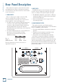
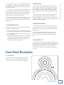
MR5mk2 High Resolution Powered Studio Monitor OWNER’S MANUAL MR5mk2 Important Safety Instructions 18. This apparatus has been equipped with a rocker-style AC mains power switch. This switch is located on the rear panel and should remain readily accessible to the user. 1. Read these instructions. 2. Keep these instructions. 3. Heed all warnings. 19. The MAINS plug or an appliance coupler is used as the disconnect device, so the disconnect device shall remain readily operable. 4. Follow all instructions. 5. Do not use this apparatus near water. 6. Clean only with a dry cloth. 7. Do not block any ventilation openings. Install in accordance with the manufacturer’s instructions. 8. Do not install near any heat sources such as radiators, heat registers, stoves, or other apparatus (including amplifiers) that produce heat. 9. Do not defeat the safety purpose of the polarized or grounding-type plug. A polarized plug has two blades with one wider than the other. A grounding-type plug has two blades and a third grounding prong. The wide blade or the third prong are provided for your safety. If the provided plug does not fit into your outlet, consult an electrician for replacement of the obsolete outlet. 10. Protect the power cord from being walked on or pinched particularly at plugs, convenience receptacles, and the point where they exit from the apparatus. 11. Only use attachments/accessories specified by the manufacturer. 12. Use only with a cart, stand, tripod, bracket, or table specified by the manufacturer, or sold with the apparatus. When a cart is used, use caution when moving the cart/apparatus combination to avoid injury from tip-over. PORTABLE CART WARNING 13. Unplug this apparatus during lightning storms or when unused for long periods of time. 14. Refer all servicing to qualified service personnel. Servicing is required when the apparatus has been damaged in any way, such as powersupply cord or plug is damaged, liquid has been spilled or objects have fallen into the apparatus, the apparatus has been exposed to rain or moisture, does not operate normally, or has been dropped. 15. This apparatus shall not be exposed to dripping or splashing, and no object filled with liquids, such as vases or beer glasses, shall be placed on the apparatus. 16. Do not overload wall outlets and extension cords as this can result in a risk of fire or electric shock. 17. This apparatus has been designed with Class-I construction and must be connected to a mains socket outlet with a protective earthing connection (the third grounding prong). CAUTION AVIS RISK OF ELECTRIC SHOCK. DO NOT OPEN RISQUE DE CHOC ELECTRIQUE. NE PAS OUVRIR CAUTION: TO REDUCE THE RISK OF ELECTRIC SHOCK DO NOT REMOVE COVER (OR BACK) NO USER-SERVICEABLE PARTS INSIDE. REFER SERVICING TO QUALIFIED PERSONNEL ATTENTION: POUR EVITER LES RISQUES DE CHOC ELECTRIQUE, NE PAS ENLEVER LE COUVERCLE. AUCUN ENTRETIEN DE PIECES INTERIEURES PAR L'USAGER. CONFIER L'ENTRETIEN AU PERSONNEL QUALIFIE. AVIS: POUR EVITER LES RISQUES D'INCENDIE OU D'ELECTROCUTION, N'EXPOSEZ PAS CET ARTICLE A LA PLUIE OU A L'HUMIDITE The lightning flash with arrowhead symbol within an equilateral triangle is intended to alert the user to the presence of uninsulated "dangerous voltage" within the product's enclosure, that may be of sufficient magnitude to constitute a risk of electric shock to persons. Le symbole éclair avec point de flèche à l'intérieur d'un triangle équilatéral est utilisé pour alerter l'utilisateur de la présence à l'intérieur du coffret de "voltage dangereux" non isolé d'ampleur suffisante pour constituer un risque d'éléctrocution. The exclamation point within an equilateral triangle is intended to alert the user of the presence of important operating and maintenance (servicing) instructions in the literature accompanying the appliance. Le point d'exclamation à l'intérieur d'un triangle équilatéral est employé pour alerter les utilisateurs de la présence d'instructions importantes pour le fonctionnement et l'entretien (service) dans le livret d'instruction accompagnant l'appareil. 2 MR5mk2 20.NOTE: This equipment has been tested and found to comply with the limits for a Class B digital device, pursuant to part 15 of the FCC Rules. These limits are designed to provide reasonable protection against harmful interference in a residential installation. This equipment generates, uses, and can radiate radio frequency energy and, if not installed and used in accordance with the instructions, may cause harmful interference to radio communications. However, there is no guarantee that interference will not occur in a particular installation. If this equipment does cause harmful interference to radio or television reception, which can be determined by turning the equipment off and on, the user is encouraged to try to correct the interference by one or more of the following measures: • Reorient or relocate the receiving antenna. • Increase the separation between the equipment and the receiver. • Connect the equipment into an outlet on a circuit different from that to which the receiver is connected. • Consult the dealer or an experienced radio/TV technician for help. CAUTION: Changes or modifications to this device not expressly approved by LOUD Technologies Inc. could void the user's authority to operate the equipment under FCC rules. 21. This apparatus does not exceed the Class A/Class B (whichever is applicable) limits for radio noise emissions from digital apparatus as set out in the radio interference regulations of the Canadian Department of Communications. ATTENTION — Le présent appareil numérique n’émet pas de bruits radioélectriques dépassant las limites applicables aux appareils numériques de class A/de class B (selon le cas) prescrites dans le réglement sur le brouillage radioélectrique édicté par les ministere des communications du Canada. 22. Exposure to extremely high noise levels may cause permanent hearing loss. Individuals vary considerably in susceptibility to noise-induced hearing loss, but nearly everyone will lose some hearing if exposed to sufficiently intense noise for a period of time. The U.S. Government’s Occupational Safety and Health Administration (OSHA) has specified the permissible noise level exposures shown in the following chart. According to OSHA, any exposure in excess of these permissible limits could result in some hearing loss. To ensure against potentially dangerous exposure to high sound pressure levels, it is recommended that all persons exposed to equipment capable of producing high sound pressure levels use hearing protectors while the equipment is in operation. Ear plugs or protectors in the ear canals or over the ears must be worn when operating the equipment in order to prevent permanent hearing loss if exposure is in excess of the limits set forth here: Duration, per day in hours 8 6 4 3 2 1.5 1 Sound Level dBA, Slow Response 90 92 95 97 100 102 105 0.5 110 0.25 or less 115 Typical Example Duo in small club Subway Train Very loud classical music The Ballard Mallard screaming at desTROYer about deadlines Loudest parts at a rock concert WARNING — To reduce the risk of fire or electric shock, do not expose this apparatus to rain or moisture. Contents • High-resolution, powered studio reference monitor IMPORTANT SAFETY INSTRUCTIONS................................................2 • Ultra-low distortion 5.25" woofer INTRODUCTION................................................................................4 • Long voice coil winding length allows high output with controlled low frequency performance • Optimally sized inverted dust cap stiffens cone for smooth response • Hyperbolic curved cone profile reduces severe cone resonances • High-output 1" silk dome tweeter • Neodymium magnet minimizes distortion and handles fast transients in dynamic source material • Ferro-fluid cooling protects against power compression • Acoustic absorption backing material provides smooth, reflection-free performance • Precision Class A/B amplification with Active protection circuits: 55W for LF / 30W for HF • Optimally sized custom waveguide provides seamless transition of HF and LF • Minimum-diffraction molded baffle imparts superior stereo imaging and depth • Adjustable HF and LF acoustic controls offer sonic tailoring to your mixing space • Flexible inputs include XLR, TRS and RCA connections • Magnetic shielding allows safe placement near computers and video monitors QUICK START............................................................................5 REAR PANEL DESCRIPTION ..............................................................6 1. SIGNAL INPUTS.................................................................6 2. INPUT LEVEL.....................................................................6 3. HIGH FREQUENCY FILTER..................................................6 4. LOW FREQ FILTER.............................................................7 5. POWER SWITCH...............................................................7 6. MAINS INPUT AND FUSE...................................................7 7. BASS REFLEX PORT...........................................................7 Owner’s Manual MR5mk2 Features FRONT PANEL DESCRIPTION.............................................................7 8. POWER INDICATOR..........................................................7 PROTECTION CIRCUITS.....................................................................8 OVEREXCURSION PROTECTION............................................8 THERMAL PROTECTION.........................................................8 INTEGRATED MAGNETIC SHIELDING......................................8 INPUT SIGNAL WIRING.........................................................8 CARE AND CLEANING.......................................................................8 APPENDIX A: SERVICE INFO.............................................................9 TROUBLESHOOTING..............................................................9 REPAIR................................................................................10 APPENDIX B: CONNECTORS............................................................11 APPENDIX C: TECHNICAL INFORMATION........................................12 MR5MK2 SPECIFICATIONS.....................................................12 MR5MK2 BLOCK DIAGRAM...................................................13 MR5MK2 LIMITED WARRANTY......................................................15 • Precisely tuned to work interchangeably with other MRmk2 monitors Don’t forget to visit our website at www.mackie.com for more information about this and other Mackie products. Correct disposal of this product. This symbol indicates that this product should not be disposed of with your household waste, according to the WEEE Directive (2002/96/EC) and your national law. This product should be handed over to an authorized collection site for recycling waste electrical and electronic equipment (EEE). Improper handling of this type of waste could have a possible negative impact on the environment and human health due to potentially hazardous substances that are generally associated with EEE. At the same time, your cooperation in the correct disposal of this product will contribute to the effective usage of natural resources. For more information about where you can drop off your waste equipment for recycling, please contact your local city office, waste authority, or your household waste disposal service. Part No. SW0893 Rev. B 05/11 ©2011 LOUD Technologies Inc. All Rights Reserved. Owner’s Manual 3 MR5mk2 Introduction The MR5mk2 Mackie Reference Monitor is the perfect solution for those ready to step up to a truly professional monitoring system. The completely re-voiced MR5mk2 features all-new high-end drivers and provides unmatched frequency response performance in its category. The MR5mk2’s precision Class A/B amplification (55W LF / 30W HF) offers class-leading power, tons of connection options and simple acoustic controls for room correction. Plus, an optimally sized custom waveguide and minimum-diffraction molded baffle work in concert to provide superior stereo imaging and depth. With unbelievable power, performance and clarity, the MR5mk2 stands alone in its class. Investments in Excellence... The MR5mk2s were designed by our expert loudspeaker and transducer engineering teams at Mackie and EAW. These compact studio monitors can be used in a variety of applications, including small project studios, surround sound editing, home theater playback, and desktop audio workstations (DAWs). High-frequency and low-frequency switches are provided on the rear panel to adjust the sound of the monitors to the characteristics of the room. Three types of input connectors are provided (XLR, 1/4-inch, and RCA), to interface with virtually any application you may have. The result? The MR5mk2 Studio Monitors are extremely accurate and versatile, with unique controls that allow you to fine-tune the sound to match your individual environment precisely. You’re gonna love these! What are they? The Advantages... The MR5mk2 Studio Monitors are two-way, bi-amplified, active monitors employing a bass reflex (ported) design for an extended low-frequency response. There are many benefits to integrating an active crossover, power amplifiers, and drivers into a single cabinet, and we’ve taken full advantage of these benefits in the design of the MR5mk2. • The crossover point is designed so that the high- and low-frequency drivers are fed only the frequencies they are best able to reproduce. • The amplifiers are designed to provide maximum acoustic output from the speakers, yet minimize the danger of speaker damage due to overdriving. 4 MR5mk2 • In addition, the amplifiers’ gain and frequency responses are individually hand-trimmed to compensate for typical manufacturing tolerances between the drivers and produce a smooth frequency response from 50 Hz to 20 kHz. • The connecting wires between the amplifier outputs and the drivers are kept to an absolute minimum, so the damping factor of the amplifier isn’t compromised by the resistance of long speaker cables. • The acoustic sum of the outputs from the two drivers are optimized electronically, as well as physically, so the amplitude response is unity and the phase difference is minimal. In short, all the complex interconnected components in the system are designed to work in harmony with each other to produce the best possible sound. All-New Transducers... The MR5mk2s feature a 5.25-inch high-precision, low-distortion woofer and a 1-inch neodymium silk dome tweeter. The high-frequency driver is mounted on a molded baffle/waveguide, which reduces diffraction and results in wide, controlled dispersion of high-frequency sounds. This widens the “sweet spot” and improves the time domain characteristics of the system. Precision Power Amplifiers... The low-frequency amplifier produces up to 55 watts continuous before clipping, while the high-frequency amplifier produces up to 30 watts continuous. Both amplifiers are Class A/B with power MOSFET outputs and active protection circuits. Cabinet Design... The cabinet is made of MDF with a textured matteblack finish. Internal bracing increases the strength and rigidity of the box. An open-cell adiabatic foam material fills the inside of the box to absorb internal reflections and dampen standing waves. We realize that you can’t wait to hook up your new Mackie MR5mk2 Studio Monitors and try them out. Nevertheless, please take the time to read this page NOW, and the rest can wait until you’re good and ready. 1. Turn the INPUT LEVEL [2] control on the back of the cabinet down (fully counterclockwise) before turning on the monitor for the first time. 2. Set the power switch [5] on the back panel off. This will prevent you from accidentally connecting a hot signal source to the monitor and getting a rude surprise. 3. Leave the High Freq [3] and Low Freq [4] Filter switches at their Normal positions. 4. Connect the line-level monitor signal from your mixer, preamp, or other signal source to the INPUT [1] jack on the MR5mk2 Studio Monitor (1⁄4-inch PHONE, XLR, or RCA). 5. Connect the supplied AC power cord to the IEC socket [6] on the back of the monitor. Plug the other end into an AC outlet properly configured with the voltage corresponding to the markings next to the IEC socket. 6. Start your signal source (tape deck, CD, DAW, or whatever), but leave the master volume control on your mixer or preamp down. 7. Turn on the power switch [5] on the MR5mk2. The power LED [8] on the front panel will illuminate. 8. Slowly turn up the INPUT LEVEL [2] control on the back of the monitor to its fully clockwise position (MAX). 9. Adjust the master volume on your mixer or preamp to a comfortably loud listening level. If the MR5mk2 gets loud really fast, turn down the INPUT LEVEL control to its center position (12 o’clock) to provide more volume control on your mixer or preamp. Enjoy the silky smooth highs and authoritative, commanding lows of the MR5mk2. Then read the rest of this manual. An Extremely Important Note on MR5mk2 Bass Response and Your Control Room. Your new MR5mk2s achieve their best bass response in a room that’s optimized for bass reproduction. A lot of factors can conspire to thwart the MR5mk2s’ extended low frequency – including room shape, room volume and acoustical treatment. This is not a cop-out or an apology. It’s plain old physics in action. Luckily we’ve armed you with some compensating controls that you can use to optimize the frequency response of the speakers in your particular room. Consider the following: Owner’s Manual Quick Start Low-Frequency Response When you put your MR5mk2s in a corner or up against walls, their bass characteristics change. The apparent loudness of the low frequencies increases when the monitors are placed close to a wall, and even more so when they are placed in a corner. If you have placed the monitors away from the walls and corners and you would like to hear a little more bass, try setting the LOW FREQ FILTER [4] switch to the +2 dB position to provide a gentle boost to the low frequencies (below 100 Hz). If it’s still not enough bass, try the +4 dB position to provide a little more bass boost. High-Frequency Response The MR5mk2s are designed to provide a smooth frequency response throughout the mid and high range. Nevertheless, you may decide that you need a little more or a little less high frequencies in your monitors while you are mixing. The HIGH FREQ FILTER [3] switch provides a gentle boost or cut in the frequencies above 5 kHz. Remember that boosting the high frequencies in the monitors can result in a duller mix, while reducing the high frequencies can result in a brighter overall mix. Additional Tidbits of Wisdom • Never listen to loud music for prolonged periods. Please see the Safety Instructions on page 2 for information on hearing protection. • When you shut down your equipment, turn off the MR5mk2 studio monitors first to prevent thumps and other noises generated by any upstream equipment from coming out the speakers. When powering up, turn on the monitors last. • Save the shipping box! You may need it someday. • Save your sales receipt in a safe place. It’s your warranty! Owner’s Manual 5 MR5mk2 Rear Panel Description This is where the signal is connected to the monitor and adjustments are made to the frequency response of the speakers to match the monitor’s location and the room’s environment. 2. INPUT LEVEL 1. SIGNAL INPUTS • The MR5mk2 is designed to operate with a +4 dBu signal when the input level control is in the max position. In other words, wide open. • Refer to the Quick Start section on page 5 for the level-setting procedure. There are three types of input connectors: XLR, 1/4-inch, and RCA. Since all three of them are connected together electrically, do not connect more than one signal at a time to the input jacks. • The XLR connector and 1/4-inch TRS (tip-ring-sleeve) connector accept a balanced signal while the RCA connector accepts an unbalanced signal. A balanced signal provides better noise rejection and is the preferred method, especially if using a cable longer than 20 feet (6 meters). • The 1/4-inch TRS jack may also accept an unbalanced signal from a 1/4-inch TS (tip-sleeve) plug. The connectors are wired as follows (per the AES/IEC standard): XLR TRS RCA Hot (+) Cold (–) Shield (Ground) Pin 2 Pin 3 Pin 1 Tip Tip Ring — WARNING: Shield Shield AVIS: RISQUE DE CHOC ELECTRIQUE — NE PAS OUVRIR TO REDUCE THE RISK OF FIRE OR ELECTRIC SHOCK, DO NOT EXPOSE THIS EQUIPMENT TO RAIN OR MOISTURE. DO NOT REMOVE COVER. NO USER SERVICEABLE PARTS INSIDE. REFER SERVICING TO QUALIFIED PERSONNEL. SERIAL NUMBER For more information on these connectors, see Appendix B on page 11. REVISION The MR5mk2 expects a line-level signal at its input. Use this control to adjust the sensitivity of the input section according to the signal strength at its input. 3. HIGH FREQUENCY FILTER This switch tailors the overall high-frequency response by ±2 dB at 5 kHz and above. Leave this switch in the “0 (NORMAL)” position unless: • You want to subtly brighten or darken the sound of the speakers. • Perhaps you have hearing loss caused by too many nights in front of a double Marshall stack. • You just like to mix on the bright side or dull side. If the mixes consistently sound dull or dark when you listen elsewhere, this usually indicates that the monitors are too bright, relative to your normal hearing. A bit less high-frequency energy usually fixes this, and the mix may be forced in this direction by reducing the high-frequency output of the monitors by using the –2 dB position of the switch. THIS DEVICE COMPLIES WITH PART 15 OF THE FCC RULES FOR THE U.S. AND ICES-003, FOR CANADA. OPERATION IS SUBJECT TO THE FOLLOWING TWO CONDITIONS: (1) THIS DEVICE MAY NOT CAUSE HARMFUL INTERFERENCE, AND (2) THIS DEVICE MUST ACCEPT ANY INTERFERENCE RECEIVED, INCLUDING INTERFERENCE THAT MAY CAUSE UNDESIRED OPERATION. INPUT TRS (BALANCED) SETTINGS XLR RCA (BALANCED) (UNBALANCED) 1 3 4 HIGH FREQ FILTER INPUT –2dB +2dB 0 (NORMAL) LOW FREQ FILTER OFF MAX 2 LEVEL +2dB +4dB 0 (NORMAL) ON 6 CAUTION: REPLACE WITH THE SAME FUSE AND RATING. DISCONNECT SUPPLY CORD BEFORE CHANGING FUSE. 7 6 MR5mk2 5 It’s a real rush to mix really loud. But remember that the resulting mix only sounds good when you play it at least that loud. However strange it may sound, mixes made at lower levels sound even better when played loud, perhaps even a bit bigger than life. Get that sound level meter out. Decide what level to mix at and use the meter to help keep mixing at that level. Your ears will thank you, and your mixes will be better for it. 4. LOW FREQUENCY FILTER This switch tailors the overall low-frequency response by +2 dB or +4 dB at 100 Hz. • For most applications, use the “0 (NORMAL)” setting. This takes the equalization circuit out of the signal path. • If a little extra low-frequency output is necessary, use the +2 dB setting. • If even more low-frequency output is necessary, use the +4 dB setting. Remember how things work in reverse, so boosting the deep bass content on playback may actually decrease it in the final mix. 5. POWER SWITCH Switch up to turn the MR5mk2 on. Make sure the level control is down before you turn it on. When the power switch is turned on and the MR5mk2 is plugged into an AC outlet, the power LED on the front of the monitor lights up to let you know the MR5mk2 is ready to go. Press the bottom of this switch to put the speaker into standby mode. It will not function, but the circuits are still live. To remove AC power, either turn off the AC supply, or unplug the power cord from the speaker and the AC supply. Owner’s Manual Conversely, if the mixes are consistently too bright, then adding some additional high-frequency energy in the monitors satisfies your ears, and the resultant mix has less HF content. 6. MAINS INPUT AND FUSE Connect the power cord to this IEC socket securely, and plug the other end into a live AC outlet. Make sure the AC outlet has the correct voltage indicated next to the IEC socket. The fuse is located behind the fuse cover, at the bottom of the IEC socket. See the “Troubleshooting” section on page 9 for information about replacing the fuse. 7. BASS REFLEX PORT A bass reflex system uses the radiation from the rear of the woofer cone to extend the low-frequency response of the speaker. The size of the port is carefully designed with respect to the volume of the cabinet and the characteristics of the woofer to produce low-frequency extension. Front Panel Description 8. Power Indicator The power indicator lights up when the power switch [5] on the back of the MR5mk2 is turned on and AC power is available at the mains input [6]. 8 Owner’s Manual 7 MR5mk2 Protection Circuits There are several protection mechanisms designed into the MR5mk2 to safeguard the loudspeakers and amplifiers from inadvertent damage. CAUTION: The protection circuits are designed to prevent damage to the loudspeakers under reasonable and sensible conditions. Should you choose to ignore the warning signs (i.e., excessive distortion), you can still damage the speakers in the MR5mk2 by overdriving them. Such damage is beyond the scope of the warranty. Overexcursion Protection A 12 dB/octave high-pass filter at 50 Hz just prior to the low-frequency amplifier prevents very low frequencies from being amplified. Excessive low-frequency energy below 50 Hz can damage the woofer by causing it to “bottom out,” also known as overexcursion, which is equivalent to a mechanical form of clipping. Thermal Protection All amplifiers produce heat. The MR5mk2 is designed to be efficient both electrically and thermally. • If for some reason the heatsink gets too hot, a thermal switch activates and turns off the amplifier. This protection operates independently for the low-frequency and high-frequency amplifiers. Therefore, it is possible for only the low frequency or high frequency amplifier to shut down while the other remains on. • When the heatsink cools down to a safe temperature, the thermal switch resets and normal operation resumes. • If the heatsink temperature again gets too hot, the shutdown process repeats. Should this happen, make sure that airflow to the rear of the cabinet is not restricted. Integrated Magnetic Shielding The MR5mk2 contains drivers with large magnetic structures. The drivers’ magnets are shielded to help prevent the magnetic field from radiating out into the environment and playing havoc with computer monitors or TV screens. Unshielded speakers can cause distortion in both the shape and color of the picture if placed too close to a CRT (cathode ray tube). If you have a particularly sensitive computer monitor or TV screen, it may be necessary to move the speakers a few inches away. 8 MR5mk2 Input Signal Wiring You should use high-quality, shielded cable to connect the signal source to the signal input jack [1] on the MR5mk2. • For balanced signals, foil shielded cables, such as Belden 8451, 8761, or 9501 are commonly used for studio wiring. • Microphone cables work well for the XLR input. • The better the shield, the better the immunity from externally induced noise (like EMI and RFI). Route the cable away from AC power cords and outlets. These are common sources for hum in an audio signal. Wall warts and line lumps are especially insidious hum inducers! Quality cables may be purchased from Mackie dealers. • In certain home theater applications, it may be necessary to connect the speaker outputs from a stereo receiver to the inputs of the MR5mk2, if the receiver doesn’t have preamp outputs or other line-level output connections. CAUTION: Do not attempt to connect a speaker output directly to the input of the MR5mk2! Speaker levels are much higher than line levels and can damage the input circuitry in the MR5mk2. However, it is possible to insert a speaker-level to line-level signal attenuator between the receiver’s speaker output and the MR5mk2’s input. The local Mackie dealer should be able to assist, or you can build your own. Care and Cleaning Mackie Reference Studio Monitors will provide many years of reliable service if you follow these guidelines. • Avoid exposing the monitors to moisture. • Avoid exposure to extreme cold (below freezing temperatures). • Use a dry cloth to clean the cabinets. Only do this when the power is turned off. If you think your Mackie product has a problem, please check out the following troubleshooting tips and do your best to confirm the problem. Visit the Support section of our website (www.mackie.com/support) where you will find lots of useful information such as FAQs, and documentation. You may find the answer to the problem without having to send your Mackie product away. Troubleshooting No Power • Our favorite question: Is it plugged in? • Make sure the power cord is securely seated in the IEC socket [6] and plugged all the way into the AC outlet. • Make sure the AC outlet is live (check with a tester or lamp). • Is the power [5] switch on the rear panel in the ON position? • Is the power indicator [8] on the front panel illuminated? If not, make sure the AC outlet is live. If so, refer to “No Sound” below. • If the power indicator is not illuminated, and you are certain that the AC outlet is live, it is possible the fuse has blown. To remove and replace the fuse: 1. Disconnect the power cord from the IEC socket. 2. Remove the fuse drawer by prying it open with a small screwdriver. It will slide all the way out. FUSE 3. Remove the fuse and replace it with an equivalent-type fuse. 115 VAC unit: 1.6 amp slo-blo (T 1.6 AL/250V) 230 VAC unit: 800 milliamp slo-blo (T 800 mAL/250V) 4. Replace the fuse drawer by pushing it all the way back into the IEC socket. If two fuses blow in a row, then something is very wrong. See the “Repair” section on the next page to find out how to proceed. No Sound • Is the power indicator [8] on the front panel illuminated? If not, refer to “No Power” above. • Is the input level [2] control turned up? • Is the signal source turned up? Make sure the signal level from the mixing console (or whatever device immediately precedes the studio monitor) is high enough to produce sound. • If it’s a stereo pair, try switching them around. For example, if a left output is presumed dead, switch the left and right cords at the monitor end. If the problem switches sides, it’s not the monitor. It could be a bad cable, or no signal from the mixer. Owner’s Manual Appendix A: Service Information Bad Sound • Is the input connector plugged completely into the jack? If using a 1⁄4" plug, make sure it is plugged all the way in. • Is it loud and distorted? Reduce the signal level at the mixer. • If possible, listen to the signal source with headphones plugged into the preamp stage. If it sounds bad there, it’s not the monitor. • Too much bass or not enough bass? Move around the room and see if the bass response changes. It’s possible your listening position coincides with a room mode where the low frequencies either become exaggerated or nulled. If so, try moving the monitors to a different position, or moving your listening position. Noise/Hum/Buzz • Check the signal cable between the mixer and the monitor. Make sure all connections are secure. These problems usually produce crackling noises, hum, or buzz. • If connecting an unbalanced output to the MR5mk2 balanced input, make sure the shield is connected to the unbalanced ground of the source and to pins 1 and 3 of the XLR. • If a CATV cable is connected to the system, try disconnecting it. If the hum goes away, call your cable carrier to check for proper grounding of the cable. • Make sure the signal cable is not routed near AC cables, power transformers, or other EMI sources (including wall warts and line lumps!). These sources usually produce hum. • Is there a light dimmer or other triac-based device on the same AC circuit as the monitor? Dimmers cause buzzing noises. Use an AC line filter or plug the monitor into a different AC circuit. • Excessive hiss is an indication of an incorrect gain setting somewhere before the speaker. • If possible, listen to the signal source with headphones plugged in. If it sounds noisy there, it’s not the monitor. Owner’s Manual 9 MR5mk2 Repair For warranty service, please refer to the warranty information on page 15. Non-warranty service for Mackie products is available at a factory-authorized service center. To locate your nearest service center, visit www.mackie.com, click “Support” and select “Locate a Service Center.” If you do not have access to our website, please call our Tech Support department at 1-800-898-3211 (normal business hours, Pacific Time), to explain the problem. They will tell you where the nearest factory-authorized service center is located in your area. Service for Mackie products living outside the United States can be obtained through local dealers or distributors. Need help with your new MR5mk2? • Visit www.mackie.com and click Support to find: FAQs, manuals, and addendums. • Email us at: [email protected]. • Telephone 1-800-898-3211 to speak with one of our splendid technical support representatives, (normal business hours, PST). 10 MR5mk2 XLR Connectors 1/4" TS Phone Plugs and Jacks XLR connectors are used to make balanced connections to the MR5mk2. They are wired as follows, according to standards specified by the AES (Audio Engineering Society). “TS” stands for Tip-Sleeve, the two connections available on a mono 1/4" phone jack or plug. They are used for unbalanced signals. It is okay to connect an unbalanced 1/4" phone plug into the 1/4" TRS phone jack on the MR5mk2. XLR Hot (+)Pin 2 Cold (–)Pin 3 Shield (Ground)Pin 1 1/4" TS Unbalanced Wiring: Hot (+) Tip Shield (Ground) Sleeve Owner’s Manual Appendix B: Connectors 2 SHIELD HOT SLEEVE TIP 1 SHIELD TIP TIP 1 3 COLD SLEEVE SLEEVE COLD 3 HOT 1 3 2 Unbalanced 1/4" Connectors SHIELD COLD 2 HOT Balanced XLR Connectors 1/4" TRS Phone Plugs and Jacks “TRS” stands for Tip-Ring-Sleeve, the three connections available on a stereo 1/4" or balanced phone jack or plug. TRS jacks and plugs are used to make balanced connections to the MR5mk2. 1/4" TRS Balanced Wiring: Hot (+) Tip Cold (–) Ring Shield (Ground) Sleeve RCA Plugs and Jacks RCA-type plugs (also known as phono plugs) and jacks are often used in home stereo and video equipment and in many other applications. They are unbalanced and electrically equivalent to a 1/4" TS phone plug. RCA Unbalanced Wiring: Hot (+) Tip Shield (Ground) Sleeve SLEEVE RING SLEEVE SLEEVE RING TIP TIP SLEEVE TIP RCA Unbalanced Connectors TIP RING TIP SLEEVE Balanced 1/4" Connectors Owner’s Manual 11 MR5mk2 Appendix C: Technical Information MR5mk2 Specifications Acoustic Performance AC Power Requirements Free Field Frequency Response: 50 Hz – 20 kHz US: Europe: Korea: Japan: Sound Pressure Level @ 1 meter, +4 dBu into Balanced Input: 104 dB SPL @ 1m Maximum SPL Per Pair: 116 dB SPL @ 1m Transducers Low Frequency: 5.25 in / 133 mm hyperbolic curved cone woofer High Frequency: Neodymium magnet driven 1 in / 25 mm silk dome tweeter 120 VAC, 60 Hz 240 VAC, 50 Hz 220 VAC, 60 Hz 100 VAC, 50/60 Hz Note: The MR5mk2 does not support multiple voltage configurations. Make sure the voltage rating for your particular model (as indicated on the rear panel near the IEC socket) corresponds with your local AC mains voltage. AC Connector: 3-pin IEC 250 VAC, 16 A male Fuse: 115 VAC: T 1.6AL/250 V 230 VAC: T 800 mAL/250 V Power Consumption: 75 watts with music, loud mix 10 watts quiescent (idle) Amplifiers Low Frequency Power: 55 watts, 4 Ω load, 110 watts peak High Frequency Power: 30 watts, 8 Ω load, 60 watts peak Type: Monolithic IC, Class AB with DMOS power stage Electronic Crossover Physical Dimensions and Weight Enclosure: 0.625 in / 15 mm thick MDF with 0.625 in / 15 mm MDF front panel Damping: Adiabatic batting Dimensions: Height: Width: Depth: Weight: 11.5 in / 292 mm 7.8 in / 197 mm 10.6 in / 269 mm 14.3 lb / 6.5 kg Crossover Type: 24 dB/octave Crossover Frequency: 3 kHz Sensitivity: +4 dBu at 300 Hz for full output Input Impedance: 20 kΩ, balanced bridging; 10 kΩ unbalanced Disclaimer Low Frequency EQ: +2 dB/+4 dB @ 100 Hz, shelving LOUD Technologies is always striving to improve our products by incorporating new and improved materials, components and manufacturing methods. Therefore, we reserve the right to change these specifications at any time without notice. High Frequency EQ: ±2 dB @ 5 kHz, shelving Equalization 7.8" / 197 mm MR5mk2 WEIGHT 14.3 lb / 6.5 kg 11.3" / 287 mm 10.6" / 269 mm 12 MR5mk2 RCA UNBALANCED LINE INPUT XLR BALANCED LINE INPUT HI-FREQUENCY POWER AMPLIFIER HIGH FREQ 1 CROSSOVER +2 dB 0 –2 dB 2 3 INPUT LEVEL +HI VDC HI-FREQ HI-FREQUENCY DRIVER TWEETER LO-FREQ 1/4" UNBALANCED LINE INPUT –HI VDC OVEREXCURSION PROTECT 34 Hz DARK SIDE OF THE MOON LO-FREQUENCY POWER AMPLIFIER LOW FREQ +HI VDC +4 dB +2 dB 0 LO-FREQUENCY DRIVER Owner’s Manual MR5mk2 Block Diagram WOOFER –HI VDC FUSE POWER POWER LED + HI VDC – TOROIDAL POWER TRANSFORMER + LO VDC – The following are trademarks or registered trademarks of LOUD Technologies Inc.: The Mackie logo, MR Series and the Running Man. This manual also contains names and marks of other companies which belong to those respective companies, and are hereby acknowledged. ©2011 LOUD Technologies Inc. All Rights Reserved. Owner’s Manual 13 MR5mk2 AVIS: RISQUE DE CHOC ELECTRIQUE — NE PAS OUVRIR WARNING: TO REDUCE THE RISK OF FIRE OR ELECTRIC SHOCK, DO NOT EXPOSE THIS EQUIPMENT TO RAIN OR MOISTURE. DO NOT REMOVE COVER. NO USER SERVICEABLE PARTS INSIDE. REFER SERVICING TO QUALIFIED PERSONNEL. SERIAL NUMBER THIS DEVICE COMPLIES WITH PART 15 OF THE FCC RULES FOR THE U.S. AND ICES-003, FOR CANADA. OPERATION IS SUBJECT TO THE FOLLOWING TWO CONDITIONS: (1) THIS DEVICE MAY NOT CAUSE HARMFUL INTERFERENCE, AND (2) THIS DEVICE MUST ACCEPT ANY INTERFERENCE RECEIVED, INCLUDING INTERFERENCE THAT MAY CAUSE UNDESIRED OPERATION. REVISION INPUT RCA (UNBALANCED) SETTINGS XLR (BALANCED) HIGH FREQ FILTER INPUT TRS (BALANCED) –2dB +2dB 0 (NORMAL) LOW FREQ FILTER OFF MAX LEVEL +2dB +4dB 0 (NORMAL) ON CAUTION: REPLACE WITH THE SAME FUSE AND RATING. DISCONNECT SUPPLY CORD BEFORE CHANGING FUSE. 14 MR5mk2 Please keep your sales receipt in a safe place. This Limited Product Warranty (“Product Warranty”) is provided by LOUD Technologies Inc. (“LOUD”) and is applicable to products purchased in the United States or Canada through a LOUD-authorized reseller or dealer. The Product Warranty will not extend to anyone other than the original purchaser of the product (hereinafter, “Customer,” “you” or “your”). For products purchased outside the U.S. or Canada, please visit www.mackie.com/warranty to find contact information for your local distributor, and information on any warranty coverage provided by the distributor in your local market. Owner’s Manual Mackie Limited Warranty LOUD warrants to Customer that the product will be free from defects in materials and workmanship under normal use during the Warranty Period. If the product fails to conform to the warranty then LOUD or its authorized service representative will at its option, either repair or replace any such nonconforming product, provided that Customer gives notice of the noncompliance within the Warranty Period to the Company at: www.mackie.com/support or by calling LOUD technical support at 1.800.898.3211 (tollfree in the U.S. and Canada) during normal business hours Pacific Time, excluding weekends or LOUD holidays. Please retain the original dated sales receipt as evidence of the date of purchase. You will need it to obtain any warranty service. For full terms and conditions, as well as the specific duration of the Warranty for this product, please visit www.mackie.com/warranty. The Product Warranty, together with your invoice or receipt, and the terms and conditions located at www.mackie.com/warranty constitutes the entire agreement, and supersedes any and all prior agreements between LOUD and Customer related to the subject matter hereof. No amendment, modification or waiver of any of the provisions of this Product Warranty will be valid unless set forth in a written instrument signed by the party to be bound thereby. Owner’s Manual 15 16220 Wood-Red Road NE • Woodinville, WA 98072 • USA United States and Canada: 800.898.3211 Europe, Asia, Central and South America: 425.487.4333 Middle East and Africa: 31.20.654.4000 Fax: 425.487.4337 • www.mackie.com E-mail: [email protected]