1
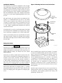
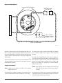
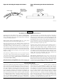
INSTALLATION AND MAINTENANCE INSTRUCTIONS
B524RB(A) and B224RB(A) Plug-in
Relay Detector Bases
A Division of Pittway
3825 Ohio Avenue, St. Charles, Illinois 60174
1-800-SENSOR2, FAX: 630-377-6495
For use with the following models:
B524RB: For use with any 500 Series detector
B224RB: For use with any 200 Series detector
Specifications
Base Diameter:
Base Height
B224RB:
B524RB:
Mounting:
Operating Temperature Range:
Operating Humidity Range:
Electrical Ratings
Operating Voltage:
Time Averaged Standby Ratings:
Relay Characteristics
Coil:
Contact Type:
Contact Relay
Resistive:
Inductive:
Set Time:
Reset Time:
6.2 inches (157 mm)
1.2 inches (31 mm)
1.4 inches (36 mm)
4-inch square box with or without plaster ring, Min Depth - 1.5 inches (13 mm)
4-inch octagon box, Min. depth - 1.5 inches (13 mm)
31/2-inch octagon box, Min. depth - 1.5 inches (13 mm)
0° to 49° C (32° to 120° F)
10% to 93% Relative Humidity (Non-condensing)
15 to 28 VDC
<500 µA @ 24 VDC
2 coil latching
1 Form C
2 A @ 30 VDC
0.3 A @ 110 VDC (with .35 PF or greater)
0.3 A @ 120 VAC (with .35 PF or greater)
1.0 A @ 30 VDC (with .6 PF or greater)
4 seconds minimum, 20 seconds maximum
1 second minimum, 8 seconds maximum
Before Installing
Please thoroughly read the system wiring and installation
manuals, and manual I56-407, Guide for Proper Use of System Smoke Detectors, which provides detailed information
on detector spacing, placement, zoning, and special applications. Copies of these manuals are available at no charge
from System Sensor. (For installation in Canada, refer to
CAN/ULC-S524, Standard for the Installation for Fire Alarm
Systems and CEC Part 1, Sec. 32.)
General Information
Form C latching relay contacts are included for the control
of an auxiliary function. The relay operates 12 seconds
(nominally) after activation of the sensor head remote annunciator output.
Mounting
The detector base mounts directly to 31/ 2- and 4-inch octagon and 4-inch square boxes, with or without a plaster
ring.
NOTICE: This manual should be left with the owner/user
of this equipment.
To mount, remove the decorative ring by rotating it in either direction to unhook the snaps. Then, separate the ring
from the base. Install the base on the box, using the screws
supplied with the junction box and the appropriate slots in
the base. Replace the decorative ring on the base and rotate it in either direction until the ring snaps in place (see
Figure 1).
IMPORTANT: The detector used with these bases must be
tested and maintained regularly following NFPA 72 requirements. The detectors should be cleaned at least once a year.
D450-16-01
1
I56-659-06
Installation Guidelines
All wiring must be installed in compliance with all applicable local codes and any special requirements of the local
authority having jurisdiction, using the proper wire sizes.
The conductors used to connect smoke detectors to control
panels and accessory devices should be color-coded to reduce the likelihood of wiring errors. Improper connections
can prevent a system from responding properly in the event
of a fire.
Figure 1. Mounting the base to an electrical box:
SNAP ON
DECORATIVE
RING
For signal wiring (the wiring between interconnected detectors), it is recommended that the wire be no smaller
than 18 gauge (1.0 square mm). However, wire sizes up to
12 gauge (3.3 square mm) can be used with the base. The
use of twisted pair wiring or shielded cable for the power
(+ and -) loop is recommended to minimize the effects of
electrical interference.
SCREWS (NOT
SUPPLIED)
If shielded cable is used, the shield connection to and from
the detector must be continuous by using wire nuts, crimping, or soldering, as appropriate, for a reliable connection.
DETECTOR
BASE
Alarm system control panels have specifications for allowable loop resistance. Consult the control panel specifications for the total loop resistance allowed before wiring the
detector loops.
BOX (NOT
SUPPLIED)
Wiring Instructions
A78-1175-21
WARNING
The base uses a latching relay that can change states if it is
subjected to mechanical shocks or jarring. As a result, even
though relay contacts are in the open state when the base is
shipped from the factory, the contacts may have closed
during shipment.
Wire the normally open (NO) line to terminal 2 (see Figure
2). Insert the normally closed (NC) line of the relay to terminal 1 and the relay common line to terminal 3. Wire the
communication lines in (+) and out (+)to terminal 4. Insert the communication line in (–) and out (–) to terminal
5. Terminal 6 is for shielded cable only (see Figure 2). If
shielded cable is used, the shield connection to and from
the detector must be continuous by using wire nuts,
crimping, or soldering to ensure a reliable connection. If
shielded cable is not used, leave terminal 6 in the screweddown position.
Connecting an auxiliary control circuit to closed relay contacts can cause an unexpected, and possibly dangerous, activation of that circuit. Therefore, do NOT connect an
auxiliary control circuit to the relay contacts (terminals 1,
2, and 3) before ensuring that the relay contacts are in their
open state. Ensure that the contacts are open by applying
power to the bases WITHOUT the sensor heads installed.
Make wiring connections by stripping about 3/8" (10 mm)
of insulation from the end of the wire. Then, slide the wire
under the clamping plate and tighten the clamping plate
screw.
D450-16-01
Check the zone wiring of all bases in the system before installing detector heads. This includes checking the wiring
for continuity, correct polarity, ground fault testing, and
performing a dielectric test.
2
I56-659-06
Figure 2. Wiring diagram:
TWISTED PAIR RECOMMENDED
LISTED COMPATIBLE CONTROL PANEL
OTHER INTELLIGENT
DEVICES
5
(–)
4
3
(+)
(COMMON)
(+)
(+)
(–)
(–)
6
(S)
2
(N.O.)
1
(N.C.)
3 RELAY COMMON
1 NORMALLY CLOSED
2 NORMALLY OPEN
CLASS A OPTIONAL WIRING
A78-1577-15
A label is affixed to the base for recording the zone, address, and type of detector being installed at the base location. This information is useful for setting the detector head
address and for verification of the sensor type required for
that location.
To activate this feature, break the tab from the detector
base as shown in Figure 3A (see page 4). Then, install the
detector.
To remove the detector from the base once the tamper-resist feature has been activated, insert a small-bladed screwdriver into the slot in the side of the base and push the
plastic lever away from the detector head (see Figure 3B,
page 4). This allows the detector to be rotated counterclockwise for removal.
Once all detector bases have been wired and mounted, and
the loop wiring has been checked, the detector heads may
be installed in the bases.
Tamper-resist Feature
NOTE: Head removal after the tamper-resist feature has
been activated first requires removal of the decorative ring.
NOTE: Do not use the tamper-resist feature if the removal
tool is to be used.
This detector base includes a tamper-resist feature that prevents its removal from the base without the use of a tool.
D450-16-01
The tamper-resist feature can be defeated by breaking and
removing the plastic lever from the base. However, this prevents the feature from being used again.
3
I56-659-06
Figure 3A. Activating the tamper-resist feature:
PLASTIC LEVER
Figure 3B. Removing the detector head from the
base:
BREAK TAB AT
DOTTED LINE BY
TWISTING TOWARD
CENTER OF BASE.
USE SMALL-BLADED
SCREWDRIVER TO
PUSH PLASTIC LEVER
IN DIRECTION OF
ARROW.
A78-1175-08
WARNING
The Limitations of Property Protection Smoke Detectors
smoldering type. This is to ensure that both can detect a wide range of
types of fires. Ionization detectors offer a broad range of fire sensing capability but they are somewhat better at detecting fast flaming fires than
slow smoldering fires. Photoelectric detectors sense smoldering fires better
than flaming fires which have little, if any, visible smoke. Because fires develop in different ways and are often unpredictable in their growth, neither type of detector is always best, and a given detector may not always
provide early warning of a specific type of fire.
The smoke detector used with this base is designed to activate and initiate emergency action, but will do so only when it is used in conjunction
with an authorized fire alarm system. This detector must be installed in
accordance with NFPA standard 72.
Smoke detectors will not work without power. AC or DC powered
smoke detectors will not work if the power supply is cut off.
Smoke detectors will not sense fires which start where smoke does not
reach the detectors. Smoldering fires typically do not generate a lot of
heat which is needed to drive the smoke up to the ceiling where the
smoke detector is usually located. For this reason, there may be large delays in detecting a smoldering fire with either an ionization type detector
or a photoelectric type detector. Either one of them may alarm only after
flaming has initiated which will generate the heat needed to drive the
smoke to the ceiling.
In general, detectors cannot be expected to provide warnings for fires resulting from inadequate fire protection practices, violent explosions, escaping gases which ignite, improper storage of flammable liquids like
cleaning solvents which ignite, other similar safety hazards, arson, smoking in bed, children playing with matches or lighters, etc. Smoke detectors
used in high air velocity conditions may have a delay in alarm due to dilution of smoke densities created by frequent and rapid air exchanges. Additionally, high air velocity environments may create increased dust
contamination, demanding more frequent maintenance.
Smoke from fires in chimneys, in walls, on roofs or on the other side of a
closed door(s) may not reach the smoke detector and alarm it. A detector
cannot detect a fire developing on another level of a building quickly or at
all. For these reasons, detectors shall be located on every level and in
every bedroom within a building.
Smoke detectors cannot last forever. Smoke detectors contain electronic
parts. Even though smoke detectors are made to last over 10 years, any
part can fail at any time. Therefore, smoke detectors shall be replaced after
being in service for 10 years. The smoke detector system that this detector
is used in must be tested regularly per NFPA 72. This smoke detector
should be cleaned regularly per NFPA 72 or at least once a year.
Smoke detectors have sensing limitations, too. Ionization detectors and
photoelectric detectors are required to pass fire tests of the flaming and
Three-Year Limited Warranty
System Sensor warrants its enclosed smoke detector base to be free from
defects in materials and workmanship under normal use and service for a
period of three years from date of manufacture. System Sensor makes no
other express warranty for this smoke detector base. No agent, representative, dealer, or employee of the Company has the authority to increase or
alter the obligations or limitations of this Warranty. The Company’s obligation of this Warranty shall be limited to the repair or replacement of any
part of the smoke detector base which is found to be defective in materials
or workmanship under normal use and service during the three year period commencing with the date of manufacture. After phoning System
Sensor’s toll free number 800-SENSOR2 (736-7672) for a Return Authorization number, send defective units postage prepaid to: System Sensor,
D450-16-01
Repair Department, RA #__________, 3825 Ohio Avenue, St. Charles, IL
60174. Please include a note describing the malfunction and suspected
cause of failure. The Company shall not be obligated to repair or replace
units which are found to be defective because of damage, unreasonable
use, modifications, or alterations occurring after the date of manufacture.
In no case shall the Company be liable for any consequential or incidental
damages for breach of this or any other Warranty, expressed or implied
whatsoever, even if the loss or damage is caused by the Company’s negligence or fault. Some states do not allow the exclusion or limitation of incidental or consequential damages, so the above limitation or exclusion may
not apply to you. This Warranty gives you specific legal rights, and you
may also have other rights which vary from state to state.
4
I56-659-06
© System Sensor 1998