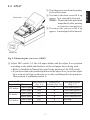
1
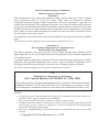
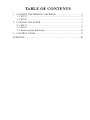
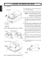
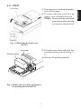
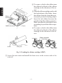
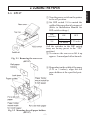
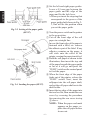
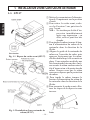
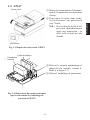
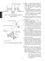
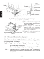
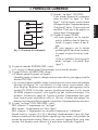
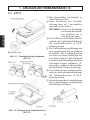
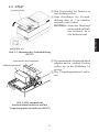
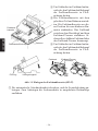
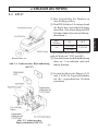
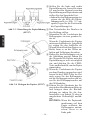
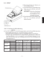
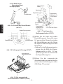
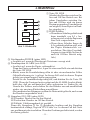
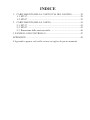
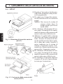
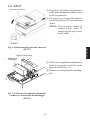
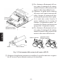
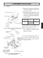
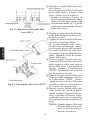
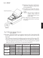
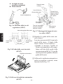
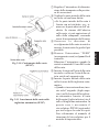
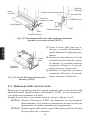
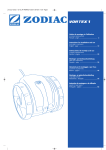
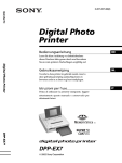
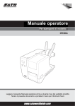
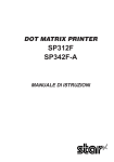
DOT MATRIX PRINTER
SP317/347F
USERS MANUAL
GUIDE D’UTILISATION
BEDIENUNGSANLEITUNG
MANUALE DI ISTRUZIONI
Federal Communications Commission
Radio Frequency Interference
Statement
This equipment has been tested and found to comply with the limits for a Class A digital
device, pursuant to Part 15 of the FCC Rules. These limits are designed to provide
reasonable protection against harmful interference when the equipment is operated in a
commercial environment. This equipment generates, uses, and can radiate radio frequency
energy and, if not installed and used in accordance with the instruction manual, may cause
harmful interference to radio communications. Operation of this equipment in a residential
area is likely to cause harmful interference in which case the user will be required to correct
the interference at his own expense.
For compliance with Federal Noise Interference Standard, this equipment requires a shielded
cable.
This statement will be applied only for the printers marketed in U.S.A.
Statement of
The Canadian Department of Communications
Radio Interference Regulations
This digital apparatus does not exceed the Class A limits for radio noise emissions from
digital apparatus set out in the Radio Interference Regulations of the Canadian Department
of Communications.
Le présent appareil numérique n’émet pas de bruits radioélectriques dépassant les limites
applicables aux appareils numériques de la classe A prescrites dans le Règlement sur le
brouillage radioélectrique édicté par le ministère des Communications du Canada.
The above statement applies only to printers marketed in Canada.
CE
Manufacturer’s Declaration of Conformity
(EC Council Directive 89/336/EEC of 3 May 1989)
This product has been designed and manufactured in accordance with the International
Standards EN50081-1/01.92 and EN50082-1/01.92 following the provisions of the
Electro Magnetic Compatibility Directive of the European Communities as of May 1989.
NOTICE
• All rights reserved. Reproduction of any part of this manual in any form whatsoever,
without STAR’s express permission is forbidden.
• The contents of this manual are subject to change without notice.
• All efforts have been made to ensure the accuracy of the contents of this manual at the
time of going to press. However, should any errors be detected, STAR would greatly
appreciate being informed of them.
• The above notwithstanding, STAR can assume no responsibility for any errors in this
manual.
©
Copyright 1996 Star Micronics Co., LTD.
TABLE OF CONTENTS
1. LOADING THE RIBBON CARTRIDGE .......................................... 2
1-1. SP317 ........................................................................................... 2
1-2. SP347 ........................................................................................... 3
2. LOADING THE PAPER ..................................................................... 5
2-1. SP317 ........................................................................................... 5
2-2. SP347 ........................................................................................... 7
2-3. Removing the Roll Paper ........................................................... 10
3. CONTROL PANEL .......................................................................... 11
APPENDIX ............................................................................................. 49
1. LOADING THE RIBBON CARTRIDGE
ENGLISH
1-1. SP317
1 Turn the power switch on the printer
to the off position.
2 To remove the front cover lift it up
approx. 3cm. and pull it forward.
NOTE: Do not touch the print head
immediately after printing
as it can be extremely hot.
3 To remove slack in the ribbon turn
the ribbon feed knob of the ribbon
cartridge in the direction of the arrow.
4 Align the ribbon cartridge guide with
the notched part of the frame. Insert
the ribbon cartridge from that position until you hear a locking sound.
Fig. 1-1 Removing the front cover (SP317)
Insert the ink ribbon between the
print head and the ribbon separator.
Make sure that the ink ribbon is not
protruding beyond the ribbon separator.
5 To remove slack in the ribbon turn
the ribbon feed knob of the ribbon
cartridge in the direction of the arrow.
6 To install the front cover reverse the
removal steps.
Fig. 1-2 Loading the ribbon cartridge (SP317)
–2–
1 Turn the power switch on the printer
to the off position.
2 To remove the front cover lift it up
approx. 3cm. and pull it forward.
NOTE: Do not touch the print head
immediately after printing
as it can be extremely hot.
Front cover
Power off
Fig. 1-3 Removing the front cover
(SP347)
3 Lift up the auto cutter and put it in a
vertical position, as shown in Fig. 14.
4 Remove the packing material.
Auto cutter
Packing material
Fig. 1-4 Raise the auto cutter and remove
the packing material (SP347)
–3–
ENGLISH
1-2. SP347
ENGLISH
Ribbon
cartridge
Frame
Ribbon feed knob
4 To remove slack in the ribbon turn
the ribbon feed knob of the ribbon
cartridge in the direction of the arrow.
5 Align the ribbon cartridge guide with
the notched part of the frame. Insert
the ribbon cartridge from that position until you hear a locking sound.
Insert the ink ribbon between the
print head and the ribbon separator.
Make sure that the ink ribbon is not
protruding beyond the ribbon separator.
6 To remove slack in the ribbon turn
the ribbon feed knob of the ribbon
cartridge in the direction of the arrow.
Ink ribbon
Guide
Lock part
Ribbon separator
Print head
OK
NO
Fig. 1-5 Loading the ribbon cartridge (SP347)
7 Lower the auto cutter and install the front cover in the reverse order of its
removal.
–4–
2-1. SP317
1 Turn the power switch on the printer
to the off position.
2 Set DIP switch 2-4 to match the
width of the paper that is being used.
(Refer to Installation Manual for
DIP switch settings.)
DIP
switches
ON
OFF
2-4
3.25 inches
3.0 inches
2.25 inches
(All the switches in the DIP switch
array are factory preset to the “ON”
position.)
3 To remove the rear cover lift it up
approx. 3cm and push it backwards.
Fig. 2-1 Removing the rear cover
(SP317)
4 Dependant on the width of the paper
(2.25 or 3 inches), align the roll
paper holders at the specified position .
Fig. 2-2 Mounting the roll paper holders
(SP317)
–5–
ENGLISH
2. LOADING THE PAPER
ENGLISH
5 Set the left and right paper guides.
Leave a 0.5 mm gap between the
paper guide and the edge of the
paper and fix the lock lever.
• When you insert the stop ring that
corresponds to the groove of the
paper guide shaft shown in Fig. 23, that will be the position when
you set the paper guide.
Fig. 2-3 Setting of the paper guide
(SP317)
Fig. 2-4 Loading the paper (SP317)
6 Turn the power switch on the printer
to the on position.
7 Cut off the front edge of the roll
paper in a straight line.
In case the front edge of the paper is
fastened with a label, etc. remove
the adhesive part of the label. If any
adhesive remains on the paper, it
will stick onto the roller of the
printer, causing the paper to misfeed.
8 Hold the roll paper as shown in the
illustration, then insert the top end
of the paper beneath the paper guide
as far as it will go and press the
“FEED” switch on the control panel
to feed the paper.
9 When the front edge of the paper
feeds out of the printer, release the
“FEED” switch. Next, insert the
rollpaper into the roll paper shaft,
and set the roll paper shaft on to the
shaft holder.
0 Insert the top edge of the paper into
the tear bar slot, then mount the rear
cover by reversing the procedure
for removing the rear cover in step
3 above.
NOTE: When the paper end mark
appears on the paper, replace the roll paper before
it runs out.
–6–
1 Turn the power switch on the printer
to the off position.
2 To remove the front cover lift it up
approx. 3cm. and pull it forward.
NOTE: Do not touch the print head
immediately after printing
as it can be extremely hot.
3 To remove the rear cover lift it up
approx. 3cm and push it backwards.
Rear cover
Power off
Fig. 2-5 Removing the rear cover (SP347)
4 Adjust DIP switch 2-4, the roll paper holder and the adjust lever position
according to the width and thickness of the roll paper that is being used.
• Refer to Installation Manual in regard to the position of the DIP switch.
• If you do not know the standard position of the adjust lever, lower the adjust
lever as far as it will go (on the rear cover side), and then pull it two positions.
That position is standard position A.
Paper
DIP switch 2-4
Adjust lever
(Fig. 4-1)
position (Fig. 2-6)
Paper width Thickness
1 sheet of paper
OFF
A
2.25 inches
Printer paper
OFF
B
1 sheet of paper
ON
A
3.0 inches
Printer paper
ON
B
1 sheet of paper
ON
A
3.25 inches
Printer paper
ON
B
–7–
Roll paper holder
(Fig. 2-7)
Used (Inner groove)
Used (Inner groove)
Used (Outer groove)
Used (Outer groove)
Not used
Not used
ENGLISH
2-2. SP347
A: One Sheet of paper
(standard position)
B: Copy paper
Roll paper
holders
ENGLISH
Lock lever
Paper guides
Adjust lever
Paper holder
mount notch
for 3-inch
paper
For 2.25-inch
paper
Paper holder
mount notch
for 3-inch
paper
Fig. 2-6 Position of the adjust lever
(SP347)
Paper guide shaft
Paper
guide
2.25 inch
3 inch
3.35 inch
For 2.25-inch
paper
Fig. 2-7 Mounting the roll paper
holders (SP347)
Paper
guide
Fig. 2-8 Roll paper guide (SP347)
5 Set the left and right paper guides.
Leave a 0.5 mm gap between the
paper guide and the edge of the
paper and fix the lock lever.
• When you insert the stop ring that
corresponds to the groove of the
paper guide shaft shown in Fig. 28, that will be the position when
you set the paper guide.
Auto cutter
6 Lift up the auto cutter and put it in a
vertical position, as shown in Fig. 29.
Fig. 2-9 Raise the auto cutter (SP347)
–8–
–9–
ENGLISH
7 Turn the power switch on the printer
to the on position.
8 Cut the tip of the roll paper in a
straight line.
• In case the front edge of the paper
is fastened with a label, etc., remove the adhesive part of the label. If any adhesive remains on
the paper, it will stick onto the
roller of the printer, causing the
paper to misfeed.
9 Observe the winding direction of
the roll paper and insert the paper
until it stops under the guide.
0 Press the FEED switch (paper feed)
on the control panel
Release the switch when the roll
paper has been fed out 10 cm from
the paper outlet.
Fig. 2-10 Loading the paper (SP347)
A Insert the roll paper shaft into the
paper roll and set it in the shaft
holder.
B Insert the tip of the roll paper in the
auto cutter paper slit.
• When using copying paper, insert
only the original (the upper paper)
into the slit of the auto cutter.
Insert the paper which is to be
copied (the lower paper) between
the platen and the auto cutter. In
Fig. 2-11 Insertion of the paper into the
this case, Rewinder PW300 (opauto cutter (SP347)
tion) will be necessary in order to
wind the paper that is copied. Refer to the user’s manual of the
rewinder for its setting method.
Auto cutter
ENGLISH
Lower
paper
Paper insertion
slit
Paper insetion
slit
Upper paper
Lower paper
Upper paper
Print head
Platen
Platen
Print head
Fig. 2-12 Insertion of the paper into the auto cutter
(When using copying paper) (SP347)
C Pull on the edge of the paper to
remove any slack and then lower the
auto cutter.
Paper
D Insert the paper through the front
outlet
cover paper outlet and then replace
the front cover by reversing the reAuto cutter
moval steps.
E To install the rear cover reverse the
removal steps.
Fig. 2-13 Paper outlet of the front cover
(SP347)
2-3. Removing the Roll Paper
Remove the rear cover then cut off the paper near the rear of the paper guide. Then
press the “FEED” switch to feed out the rest of the paper that is remaining in the
unit.
When the paper runs out, a buzzer will sound four times per cycle for two cycles.
NOTE 1. Press the “FEED” switch to remove the rest of the paper that is in
the printer. (If you remove the paper by hand, the paper could
wrinkle or slip causing it to jam.)
NOTE 2. When the paper end mark appears on the paper, replace the roll
paper before it runs out.
– 10 –
Fig. 3-1 Control panel
1 “ON LINE” switch
Switches the printer between “ON
LINE” and “OFF LINE”. Whenever the printer switches between
“ON LINE” and “OFF LINE”, the
buzzer gives one short beep (“ON
LINE” and “OFF LINE” switching
is possible only when the paper is
loaded in the printer.)
2 “FEED” switch
• When this switch is pressed and
then released within 0.5 sec., the
paper feeds one line.
• When this switch is depressed for
more than 0.5 sec., the paper feeds
continuously.
(The above paper feed operation
is possible for both “ON LINE”
and “OFF LINE” modes.)
3 “POWER” lamp (green LED)
• Lights when the power for the printer is on.
4 “ALARM” lamp (red LED)
• Lights when the paper is out.
If the paper is out, load a new roll then press the “ON LINE” switch.
• Flashes when the front cover is open or a mechanical error (motor lock etc.)
occurs. The buzzer will give one short beep followed by a long beep.
Mount the front cover properly and press the “ON LINE” switch. If the
buzzer still sounds and the “ALARM” lamp flashes, this signifies that a
mechanical error has occurred. Locate the cause of the error and turn the
power for the printer off and back on again to reset the printer.
(In case of a mechanical error, the data will not be cleared even if the power
is turned off.)
5 “ON LINE” lamp (green LED)
LED lit: Printer is ON LINE
LED off: Printer is OFF LINE
LED flashes: Validation printing mode is set.
When all lamps 3 to 5 light simultaneously and the buzzer sounds continuously, a CPU error has occurred. In case of a CPU error, turn off the power then
turn it on again. When turning off the power, the data will be cleared.
– 11 –
ENGLISH
3. CONTROL PANEL
TABLE DES MATIÈRES
1. INSTALLATION D’UNE CARTOUCHE DE RUBAN .................. 14
1-1. SP317 ......................................................................................... 14
1-2. SP347 ......................................................................................... 15
2. CHARGEMENT DU PAPIER .......................................................... 17
2-1. SP317 ......................................................................................... 17
2-2. SP347 ......................................................................................... 19
2-3. Enlèvement d’un rouleau de papier ........................................... 22
3. PANNEAU DE COMMANDE ......................................................... 23
APPENDICE ........................................................................................... 49
L’appendice n’est pas traduit.
– 13 –
1. INSTALLATION D’UNE CARTOUCHE DE RUBAN
1-1. SP317
FRANÇAIS
1 Mettez le commutateur d’alimentation de l’imprimante sur la position
d’arrêt.
2 Pour retirer le cache avant, soulevez-le d’environ 3 cm, puis tirez-le
vers l’avant.
N.B. : Ne touchez pas la tête d’impression immédiatement
après une impression ; en
effet, celle-ci peut être très
chaude.
3 Pour tendre le ruban, tournez le bouton d’alimentation du ruban de la
cartouche dans la direction de la
flèche.
4 Alignez le guide de la cartouche de
ruban sur l’encoche du cadre, puis
Fig. 1-1 Dépose du cache avant (SP317)
appuyez légèrement sur la cartouche de ruban afin qu’elle se mette en
place. Vous entendrez un déclic une
fois la cartouche bien en place. Insérez ensuite le ruban encreur entre la
tête d’impression et la protection du
ruban. Assurez-vous que le ruban
encreur ne dépasse pas la protection
du ruban.
5 Pour tendre le ruban, tournez le
bouton d’alimentation du ruban de
la cartouche dans la direction de la
flèche.
6 Pour remonter le cache avant, effectuez les étapes de la dépose en sens
inverse.
Fig. 1-2 Installation d’une cartouche de
ruban (SP317)
– 14 –
Cache avant
1 Mettez le commutateur d’alimentation de l’imprimante sur la position
d’arrêt.
2 Pour retirer le cache avant, soulevez-le d’environ 3 cm, puis tirez-le
vers l’avant.
N.B. : Ne touchez pas la tête d’impression immédiatement
après une impression ; en
effet, celle-ci peut être très
chaude.
Hors tension
Fig. 1-3 Dépose du cache avant (SP347)
Coupoir
Autoautomatique
cutter
Emballage de
protection
Packing
material
3 Relevez le coupoir automatique et
placez-le à la verticale, comme illustré à la figure 1-4.
4 Retirez l’emballage de protection.
Fig. 1-4 Relèvement du coupoir automatique et enlèvement de l’emballage de
protection (SP347)
– 15 –
FRANÇAIS
1-2. SP347
Cartouche
de ruban
FRANÇAIS
Bouton d’alimentation
du ruban
Cadre
4 Pour tendre le ruban, tournez le bouton d’alimentation du ruban de la
cartouche dans la direction de la
flèche.
5 Alignez le guide de la cartouche de
ruban sur l’encoche du cadre, puis
appuyez légèrement sur la cartouche de ruban afin qu’elle se mette en
place. Vous entendrez un déclic une
fois la cartouche bien en place. Insérez ensuite le ruban encreur entre la
tête d’impression et la protection du
ruban. Assurez-vous que le ruban
encreur ne dépasse pas la protection
du ruban.
6 Pour tendre le ruban, tournez le bouton d’alimentation du ruban de la
cartouche dans la direction de la
flèche.
Ruban encreur
Guide
Verrouillage
Protection
du ruban
Ribbon
separator
Tête
d’impression
Print
head
OK
NO
NON
Fig. 1-5 Installation d’une cartouche de ruban (SP347)
7 Rabaissez le coupoir automatique et replacez le cache avant en inversant les
étapes de sa dépose.
– 16 –
2. CHARGEMENT DU PAPIER
1 Mettez le commutateur d’alimentation de l’imprimante sur la position
d’arrêt.
2 Réglez l’interrupteur DIP 2-4 en
fonction de la largeur du papier utilisé. (Se référer au Manuel d’installation pour les réglages des
microrupteurs).
Interrupteurs
DIP
2-4
ON
OFF
3,25 pouces
2,25 pouces
3,0 pouces
(Chacun des interrupteurs DIP sont
préréglés sur la position “OUI”.)
3 Pour retirer le cache arrière, releFig. 2-1 Dépose du cache arrière (SP317)
vez-le d’environ 3 cm, puis repoussez-le vers l’arrière.
4 Insérez les attaches de rouleau de
papier dans les encoches correspondant à la largeur du papier utilisé
(2,25 ou 3 pouces).
Fig. 2-2 Montage des attaches pour
rouleau de papier (SP317)
– 17 –
FRANÇAIS
2-1. SP317
FRANÇAIS
5 Réglez la position des guides de
papier gauche et droit. Veillez à
laisser un espace de 0,5 mm entre
l’extrémité du guide et du papier,
puis bloquez le levier de
verrouillage.
• Pour régler la position des guides
de papier, placez les anneaux d’arrêt dans les espaces sur l’axe des
guides de papier qui correspondent à la largeur du papier à charger (voyez la figure 2-3).
Fig. 2-3 Positionnement des guides de
papier (SP317)
6 Mettez le commutateur d’alimentation de l’imprimante sur la position
de marche.
7 Coupez l’extrémité du papier en
veillant à couper droit.
Si l’extrémité du papier est fixée à
l’aide d’un adhésif, il convient de
l’éliminer. En effet, toute trace de
matière adhésive sur le papier que
vous insérez dans l’imprimante risque d’adhérer au rouleau d’impression et d’empêcher l’alimentation
correcte du papier.
8 Placez le rouleau de papier comme
illustré, puis insérez l’extrémité du
papier aussi loin que possible sous
le guide de papier et enfoncez ensuite la touche d’avance FEED du
panneau de commande afin de faire
avancer le papier.
9 Une fois que le papier ressort par la
fente de sortie de l’imprimante, relâchez la touche d’avance FEED.
Insérez ensuite l’axe pour rouleau
de papier dans le rouleau de papier,
Fig. 2-4 Chargement du papier (SP317)
puis mettez l’axe en place en le
fixant dans les encoches de maintien.
0 Insérez l’extrémité du papier dans
la fente de la barre de déchirage,
puis remettez le cache arrière en
place en inversant l’ordre de la dépose décrit au point 3 ci-avant.
N.B. : N’attendez pas que le rouleau soit épuisé avant de
remplacer le rouleau de papier ; remplacez-le dès que
la marque de fin de rouleau
est apparente.
– 18 –
1 Mettez le commutateur d’alimentation de l’imprimante sur la position
d’arrêt.
2 Pour retirer le cache avant, soulevez-le d’environ 3 cm, puis tirez-le
vers l’avant.
N.B. : Ne touchez pas la tête d’impression immédiatement
après une impression ; en
effet, celle-ci peut être très
chaude.
3 Pour retirer le cache arrière, relevez-le d’environ 3 cm, puis repoussez-le vers l’arrière.
Cache arrière
Hors tension
Fig. 2-5 Dépose du cache arrière (SP347)
4 Réglez l’interrupteur DIP 2-4, les attaches pour rouleau de papier et le levier
d’ajustement en fonction de la largeur et de l’épaisseur du rouleau de papier
utilisé.
• Les réglages des interrupteurs DIP sont expliqués dans le Guide d’installation.
• Pour trouver la position standard A du levier d’ajustement, abaissez celuici le plus possible (côté cache arrière), puis relevez-le de deux crans.
Papier
Largeur du papier Épaisseur
2,25 pouces
3,0 pouces
3,25 pouces
Interrupteur DIP 2-4
Position du levier
(Fig. 4-1)
d’ajustement (Fig. 2-6)
Attaches pour rouleau
de papier (Fig. 2-7)
1 feuille de papier
OFF
A
Utilisés (encoches intérieures)
Papier d’imprimante
OFF
B
Utilisés (encoches intérieures)
1 feuille de papier
ON
A
Utilisés (encoches extérieures)
Papier d’imprimante
ON
B
Utilisés (encoches extérieures)
1 feuille de papier
ON
A
Pas utilisés
Papier d’imprimante
ON
B
Pas utilisés
– 19 –
FRANÇAIS
2-2. SP347
A: Une feuille de papier
(position standard)
B: Papier de copie
Attaches pour
rouleau de papier
Levier de
verrouillage
Guides du papier
Levier d’ajustement
Encoche de
fixation pour
support de papier
de 3 pouces
FRANÇAIS
Pour papier de
2,25 pouces
Encoche de fixation
pour support de
papier de 3 pouces
Fig. 2-6 Positionnement du levier d’ajustement (SP347)
Axe de guides de papier
Guide de
papier
2,25 pouces
3 pouces
3,25 pouces
Guide de
papier
Fig. 2-8 Guide de rouleau de papier
(SP347)
Auto cutter
Coupoir
automatique
Pour papier de
2,25 pouces
Fig. 2-7 Fixation des attaches pour
rouleau de papier (SP347)
5 Réglez la position des guides de
papier gauche et droit. Veillez à
laisser un espace de 0,5 mm entre
l’extrémité du guide et du papier,
puis bloquez le levier de
verrouillage.
• Pour régler la position des guides
de papier, placez les anneaux d’arrêt dans les espaces sur l’axe des
guides de papier qui correspondent à la largeur du papier à charger (voyez la figure 2-8).
6 Relevez le coupoir automatique et
placez-le à la verticale, comme illustré à la figure 2-9.
Fig. 2-9 Relèvement du coupoir automatique (SP347)
– 20 –
– 21 –
FRANÇAIS
7 Mettez le commutateur d’alimentation de l’imprimante sur la position
de marche.
8 Coupez l’extrémité du papier en
veillant à couper droit.
• Si l’extrémité du papier est fixée à
l’aide d’un adhésif, il convient de
l’éliminer. En effet, toute trace de
matière adhésive sur le papier que
vous insérez dans l’imprimante
risque d’adhérer au rouleau et
d’empêcher l’alimentation correcte du papier.
9 Placez le rouleau de papier comme
illustré, puis insérez l’extrémité du
papier aussi loin que possible sous
le guide de papier.
0 Enfoncez ensuite la touche d’avance
FEED du panneau de commande.
Faire avancer le papier, de sorte
qu’il ressorte de 10 cm par la fente
Fig. 2-10 Chargement du papier (SP347)
de sortie de l’imprimante, puis relâchez la touche d’avance.
A Insérez ensuite l’axe pour rouleau
de papier dans le rouleau de papier,
puis mettez l’axe en place en le
fixant dans les encoches de maintien.
B Insérez l’extrémité du papier dans
la fente de la barre de déchirage.
• Quand vous employez du papier
de copie, insérez uniquement l’original (la première feuille de papier) dans la fente du coupoir autoFig. 2-11 Insertion du papier dans le
matique. Insérez le papier de cocoupoir automatique (SP347)
pie (la deuxième feuille de papier)
entre le cylindre et le coupoir automatique. Il est nécessaire d’installer une rebobineuse PW300 (vendue en option) afin de pouvoir
rebobiner le papier de copie. Consultez le guide de l’utilisateur de
la rebobineuse pour apprendre
comment faire rebobiner le papier
de copie.
Coupoir
automatique
Deuxième
feuille
Fente d’insertion
du papier
Fente d’insertion
du papier
Première feuille
Deuxième feuille
FRANÇAIS
Première feuille
Tête d’impression
Cylindre d’impression
Cylindre d’impression
Tête d’impression
Fig. 2-12 Insertion du papier dans le coupoir automatique
(avec papier de copie) (SP347)
C Tirez sur l’extrémité du papier afin
de tendre le papier, puis rabaisser le
coupoir automatique.
Fente de
D
Insérez le papier par la fente de
sortie du
papier
papier du cache avant, puis remettez le cache avant en place en inversant l’ordre de sa dépose.
Coupoir
automatique
E Replacez le cache arrière en inversant l’ordre de sa dépose.
Fig. 2-13 Fente de sortie du cache avant
(SP347)
2-3. Enlèvement d’un rouleau de papier
Retirer le cache arrière, puis coupez le papier juste derrière le guide de papier.
Enfoncez la touche d’avance FEED afin de faire sortir le reste du papier qui se
trouve toujours dans l’imprimante.
Quand tout le papier est sorti, deux cycles de quatre bips sonores retentissent.
N.B. 1 : Enfoncez la touche d’avance FEED pour éliminer le reste du papier
qui se trouve dans l’imprimante.
(Si vous retirez le papier à la main, celui-ci risque de se chiffonner
ou de se mettre de travers et de causer un bourrage.)
N.B. 2 : N’attendez pas que le rouleau soit épuisé avant de remplacer le
rouleau de papier ; remplacez-le dès que la marque de fin de rouleau
est apparente.
– 22 –
1 Touche “en ligne” ON LINE
Cette touche permet de commuter
entre les états “en ligne” et “hors
POWER
ligne”. Un bip sonore court retentit
3
à chaque fois que l’imprimante passe
ALARM
4
d’un état à l’autre. Vous ne pouvez
modifier l’état que si du papier est
5
chargé dans l’imprimante.
ON LINE
2 Touche d’avance FEED
1
• Si vous appuyez sur la touche,
FEED
puis la relâchez dans la demi-se2
conde, le papier avance d’une ligne.
• Si vous appuyez sur la touche
Fig. 3-1 Panneau de commande
pendant plus d’une demi-seconde,
le papier avance de façon continue.
(Cela est valable à la fois pour le
mode “en ligne” et le mode “hors
ligne”.)
3 Voyant de marche POWER (DEL verte)
• Ce voyant s’allume quand l’imprimante est en état de marche.
4 Voyant d’alerte ALARM (DEL rouge)
• S’allume quand le papier est épuisé.
Quand le papier est épuisé, charger un nouveau rouleau, puis appuyez sur la
touche ON LINE.
• Ce voyant clignote quand le cache avant est ouvert ou une erreur mécanique
(blocage de moteur, etc.) est détectée. Un bip sonore court retentit, suivi
d’un long bip. Replacez correctement le cache avant, puis appuyez sur la
touche ON LINE. Si les bips sonores retentissent toujours et si le voyant
ALARM clignote toujours, cela signifie qu’une erreur mécanique s’est
produite. Localisez la cause de l’erreur et mettez l’imprimante hors, puis
sous tension pour réinitialiser celle-ci. (En cas d’erreur mécanique, les
données ne sont pas effacées quand vous mettez l’imprimante hors tension.)
5 Voyant “en ligne” ON LINE (DEL verte)
DEL allumée : l’imprimante est “en ligne”
DEL éteinte : l’imprimante est “hors ligne”
DEL clignote : l’imprimante est en mode d’impression “validation”
Quand tous les voyants 3 à 5 s’allument simultanément et que des bips
sonores retentissent de façon répétée signifie qu’une erreur s’est produite au
niveau du processeur central. Dans ce cas, mettez l’appareil hors, puis sous
tension. Les données sont effacées à la mise hors tension de l’appareil.
– 23 –
FRANÇAIS
3. PANNEAU DE COMMANDE
INHALTSVERZEICHNIS
1. EINLEGEN DER FARBBANDKASSETTE ................................... 26
1-1. SP317 ......................................................................................... 26
1-2. SP347 ......................................................................................... 27
2. EINLEGEN DES PAPIERS .............................................................. 29
2-1. SP317 ......................................................................................... 29
2-2. SP347 ......................................................................................... 31
2-3. Entfernen des Rollenpapiers ...................................................... 34
3. BEDIENFELD .................................................................................. 35
ANHANG ................................................................................................ 49
Der Anhang erscheint nur im englischen Teil dieser Bedienungsanleitung
– 25 –
1. EINLEGEN DER FARBBANDKASSETTE
1-1. SP317
DEUTSCH
1 Den Netzschalter am Drucker in
Aus-Stellung stellen.
2 Zum Abnehmen der Frontabdeckung diese ca. 3 cm anheben,
und nach vorne ziehen.
HINWEIS: Nicht den Druckkopf
sofort nach dem Drukken berühren, da er
sehr heiß sein kann.
3 Um Schlaufen im Farbband aufzuwickeln, den Farbbandzuführknopf
der Farbbandkassette in Pfeilrichtung drehen.
4 Die Farbbandkassettenführung mit
dem eingekerbten Teil am Rahmen
ausrichten. Die Farbbandkassette
aus dieser Position eindrücken, bis
Abb. 1-1 Frontabdeckung abnehmen
sie hörbar einrastet. Das Farbband
(SP317)
zwischen dem Druckkopf und dem
Farbband-Trenner einführen. Sicherstellen, daßkein Farbband über
den Farbband-Trenner herausragt.
5 Um Schlaufen im Farbband aufzuwickeln, den Farbbandzuführknopf
der Farbbandkassette in Pfeilrichtung drehen.
6 Zum Anbringen der Frontabdeckung
die Ausbauschritte in umgekehrter
Reihenfolge ausführen.
Abb. 1-2 Einlegen der Farbbandkassette
(SP317)
– 26 –
1-2. SP347
Frontabdeckung
DEUTSCH
1 Den Netzschalter des Druckers in
Aus-Stellung stellen.
2 Zum Abnehmen der Frontabdeckung diese ca. 3 cm anheben,
und nach vorne ziehen.
HINWEIS: Nicht den Druckkopf
sofort nach dem Drukken berühren, da er
sehr heißsein kann.
Netzschalter aus
Abb. 1-3 Abnehmen der Frontabdeckung
(SP347)
3 Die automatische Abschneideinheit
anheben und in vertikale Position
stellen, wie in der Abbildung 1-4
gezeigt.
4 Das Verpackungsmaterial entfernen.
Auto
cutter
Automatische
Abscneideinheit
Packing material
Verpackungsmaterial
Abb. 1-4 Die automatische
Abschneideinheit anheben, und das
Verpackungsmaterial entfernen (SP347)
– 27 –
Farbbandkassette
DEUTSCH
Farbbandzuführknopf
Rahmen
4 Um Schlaufen im Farbband aufzuwickeln, den Farbbandzuführknopf
der Farbbandkassette in Pfeilrichtung drehen.
5 Die Farbbandkassette mit dem
gekerbten Teil am Rahmen ausrichten. Die Farbbandkassette aus dieser Position bis zum hörbaren Einrasten eindrücken. Das Farbband
zwischen dem Druckkopf und dem
Farbband-Trenner einführen. Sicherstellen, daßkein Farbband über
den Farbband-Trenner herausragt.
6 Um Schlaufen im Farbband aufzuwickeln, den Farbbandzuführknopf
der Farbbandkassette in Pfeilrichtung drehen.
Farbband
Führung
Farbband-Trenner
Ribbon separator
Druckkopf
Print head
OK
Verriegelungsteil
NO
NEIN
Abb. 1-5 Einlegen der Farbbandkassette (SP347)
7 Die automatische Abschneideinheit absenken, und die Frontabdeckung anbringen. Zum Anbringen die Ausbauschritte in umgekehrter Reihenfolge
ausführen.
– 28 –
2. EINLEGEN DES PAPIERS
2-1. SP317
DIPSchalter
ON
OFF
2-4
3,25 Zoll
3,0 Zoll
2,25 Zoll
(Alle Schalter in der DIP-Schalterleiste
sind ab Werk auf “ON” gestellt.)
3 Zum Entfernen der Rückabdeckung
diese ca. 3 cm anheben und nach
Abb. 2-1 Entfernen der Rückabdeckung
hinten drücken.
(SP317)
4 Je nach der Breite des Papiers (2,25
oder 3 Zoll) die Papierrollenhalter
auf die vorgeschriebene Position
ausrichten.
Abb. 2-2 Anbringen der
Papierrollenhalter (SP317)
– 29 –
DEUTSCH
1 Den Netzschalter des Druckers in
Aus-Stellung stellen.
2 Den DIP-Schalter 2-4 entsprechend
der Breite des verwendeten Papiers
einstellen. (Die Einstellung der DIP
Schalter finden Sie im Installationshandbuch.)
5 Stellen Sie die linke und rechte
Papierführung ein. Lassen Sie einen
0,5 mm breiten Abstand zwischen
Papierführung und Papierkante und
stellen Sie den Sperrhebel fest.
• Indem Sie den Sicherungsring einsetzen, der der Rille der Papierführungswelle in Abb. 2-3 entspricht, legen Sie die Position für
die Papierführung fest.
Abb. 2-3 Einstellung der Papierführung 6 Den Netzschalter des Druckers in
Ein-Stellung stellen.
(SP317)
DEUTSCH
7 Schneiden Sie die Vorderkante des
Rollenpapiers in einer geraden Linie ab.
Wenn die Vorderkante des Papiers
mit einem Aufkleber etc. festgeklebt
ist, ziehen Sie den Aufkleber ab.
Wenn Klebstoff auf dem Papier verbleibt, kann er an der Walze anhaften und Fehleinzug bewirken.
8 Halten Sie das Rollenpapier wie in
der Abbildung gezeigt, führen Sie
das Oberende des Papiers unter der
Papierführung so weit wie möglich
ein, und drücken Sie die FEEDTaste am Bedienfeld, um das Papier
einzuziehen.
9 Wenn die Vorderkante des Papiers
aus dem Drucker ausgegeben wird,
lassen Sie die FEED-Taste los. Danach setzen Sie das Rollenpapier
auf die Rollenpapierwalze und setzen Sie die Rollenpapierwalze auf
den Wellenhalter.
Abb. 2-4 Einlegen des Papiers (SP317) 0 Führen Sie die Oberkante des Papiers in den Abreißkantenschlitz ein,
und bringen dann die Rückabdeckung an, indem Sie die Ausbauschritte von Schritt 3 oben in
umgekehrter Reihenfolge ausführen.
HINWEIS: Wenn die Papierendmarkierung auf dem
Papier erscheint, das
Rollenpapier austauschen, bevor es zu
Ende geht.
– 30 –
1 Den Netzschalter des Druckers in
Aus-Stellung stellen.
2 Zum Entfernen der Frontabdeckung
diese ca. 3 cm anheben und nach
vorne ziehen.
HINWEIS: Nicht den Druckkopf
sofort nach dem Drukken berühren, da er
sehr heiß sein kann.
3 Zum Entfernen der Rückabdeckung
diese ca. 3 cm anheben und nach
hinten drücken.
Rückabdeckung
Netzschalter aus
Abb. 2-5 Abnehmen der Rückabdeckung
(SP347)
4 Den DIP-Schalter 2-4, den Rollenpapierhalter und die Einstellhebelposition
entsprechend der Breite des verwendeten Papiers einstellen.
• Die DIP-Schalterstellungen sind der Aufstellanleitung zu entnehmen.
• Wenn Sie die Normalposition des Einstellhebels nicht kennen, senken Sie
den Einstellhebel so weit wie möglich (an der Rückabdeckungsseite) ab,
und ziehen ihn dann um zwei Stellungen nach oben. Diese Stellung ist die
Normalposition A.
Papier
DIP-Schalter 2-4 Einstellhebel(Abb. 4-1) position (Abb. 2-6)
Papierbreite Dicke
1 Blatt Papier
OFF
A
2,25 Zoll
Druckerpapier
OFF
B
1 Blatt Papier
ON
A
3,0 Zoll
Druckerpapier
ON
B
1 Blatt Papier
ON
A
3,25 Zoll
Druckerpapier
ON
B
– 31 –
Rollenpapierhalter
(Abb. 2-7)
Verwendet (Innenrille)
Verwendet (Innenrille)
Verwendet (Außenrille)
Verwendet (Außenrille)
Nicht verwendet
Nicht verwendet
DEUTSCH
2-2. SP347
A: Ein Blatt Papier
(Normalposition)
B: Kopierpapier
Rollenpapierhalter
Sperrhebel
Papierführungen
Einstellhebel
PapierhalterHaltekerbe für
3-Zoll-Papier
Für 2,25-ZollPapier
DEUTSCH
Abb. 2-6 Position des Einstellhebels
(SP347)
PapierhalterHaltekerbe für
3-Zoll-Papier
Papierführungswelle
Für 2,25-Zoll-Papier
Abb. 2-7 Anbringen der
Rollenpapierhalter (SP347)
5 Stellen Sie die linke und rechte
Papierführung ein. Lassen Sie einen
2,25 Zoll
Papierführungen
Papierführungen 0,5 mm großen Abstand zwischen
3 Zoll
der Papierführung und der Kante
3,25 Zoll
des Papiers und befestigen Sie den
Sperrhebel.
• Indem Sie den Sicherungsring einsetzen, der der Rille der PapierAbb. 2-8 Rollenpapierführung (SP347)
führungswelle in Abb. 2-8 entspricht, legen Sie die Position für
Automatische
Auto
cutter
Abschneideinheit
die Papierführung fest.
6 Heben Sie die automatische
Abschneideinheit an, und stellen Sie
sie in senkrechte Stellung wie in der
Abbildung 2-9 gezeigt.
Abb. 2-9 Die automatische
Abschneideinheit anheben (SP347)
– 32 –
– 33 –
DEUTSCH
7 Den Netzschalter des Druckers in
Ein-Stellung stellen.
8 Schneiden Sie die Vorderkante des
Rollenpapiers in einer geraden Linie ab.
• Wenn die Vorderkante des Papiers mit einem Aufkleber etc.
festgeklebt ist, ziehen Sie den
Aufkleber ab. Wenn Klebstoff auf
dem Papier verbleibt, kann er an
der Walze anhaften und Fehleinzug bewirken.
9 Beachten Sie die Wickelrichtung
des Rollenpapiers, und setzen Sie
das Papier ein, bis es unter der Führung stoppt.
0 Drücken Sie die FEED-Taste
(Papiervorschub) am Bedienfeld.
Lassen Sie die Taste los, wenn das
Abb. 2-10 Papier einlegen (SP347)
Rollenpapier 10 cm aus dem Papierauslauf ausgegeben worden ist.
A Setzen Sie die Rollenpapierwelle in
die Papierrolle ein, und setzen Sie
diese in den Wellenhalter ein.
B Führen Sie die Oberkante des
Rollenpapiers in den Schlitz der
automatischen Abschneideinheit
ein.
• Bei Verwendung von Durchschlagpapier setzen Sie nur das
Originalpapier (obere Papier) in
den Schlitz in der automatischen
Abb. 2-11 Papier in die automatische
Abschneideinheit ein. Führen Sie
Abschneideinheit legen (SP347)
das Kopierpapier (das untere Papier) zwischen Druckwalze und
automatischer Abschneideinheit
ein. In diesem Fall ist der
Rückwickler PW300 Sonderzubehör erforderlich, um das
Durchschlagpapier aufzuwickeln.
Anbringen des Rückwicklers siehe seine Bedienungsanleitung.
Automatische
Abschneideinheit
Unteres
Papier
Papiereinführschlitz
Oberes Papier
Papiereinführschlitz
Unteres Papier
Oberes PapierI
Druckwalze
Druckkopf
Druckwalze
Druckkopf
DEUTSCH
Abb. 2-12 Einsetzen des Papiers in den automatischen Abschneider (bei Verwendung von Durchschlagpapier) (SP347)
C Ziehen Sie die Kante des Papierstau, um Schlaufen zu beseitigen,
und senken Sie dann die automatische Abschneideinheit ab.
D Führen Sie das Papier durch den
Papierauslaß Papierauslaß in der Frontabdeckung,
und setzen Sie dann die Frontabdeckung wieder auf, indem Sie die
Automatische
Ausbauschritte in umgekehrter ReiAbschneideinheit
henfolge ausführen.
E Zum Einbauen der Rückabdeckung
die Ausbauschritte in umgekehrter
Reihenfolge ausführen.
Abb. 2-13 Papierausla· an der Frontabdeckung (SP347)
2-3. Entfernen des Rollenpapiers
Nehmen Sie die Rückabdeckung ab, und schneiden Sie das Papier in der Nähe der
Papierführung ab. Dann drücken Sie die FEED-Taste, um den Rest des Papiers
auszugeben, der noch in der Einheit ist.
Wenn das Papier verbraucht ist, wird ein Tonsignal bestehend aus zweimal vier
Tönen ausgegeben.
HINWEIS 1. Durch Drücken der FEED-Taste wird der Rest des noch im
Drucker befindlichen Papiers ausgegeben. (Wenn Sie das
Papier mit der Hand entnehmen, kann es knittern oder
verrutschen und einen Papierstau bewirken.)
HINWEIS 2. Wenn die Papier-Verbraucht-Markierung auf dem Papier erscheint, tauschen Sie die Rolle aus, bevor das Papier ganz zu
Ende ist.
– 34 –
POWER
3
ALARM
4
5
ON LINE
1
FEED
2
Abb. 3-1 Bedienfeld
1 Taste ON LINE
Schaltet den Drucker zwischen Online und Off-line Betrieb um. Bei
jedem Umschalten zwischen Online und Off-line wird ein kurzer
Piepton ausgegeben (Umschalten ist
nur möglich, wenn Papier im Drukker eingelegt ist.)
2 FEED-Schalter
• Wenn dieser Schalter gedrückt und
dann innerhalb von 0,5 s losgelassen wird, wird das Papier um
eine Zeile vorgeschoben.
• Wenn dieser Schalter länger als
0,5 s gedrückt gehalten wird, wird
das Papier kontinuierlich vorgeschoben. (Der obige Vorschubvorgang ist sowohl im On-line als
auch im Off-line Betrieb möglich.)
3 Netzlämpchen POWER (grüne LED)
• Leuchtet auf, wenn der Drucker mit Netzstrom versorgt wird.
4 Warnlämpchen ALARM (rote LED)
• Leuchtet auf, wenn das Papier verbraucht ist.
Wenn das Papier verbraucht ist, legen Sie eine neue Rolle ein und drücken
die Taste ON LINE.
• Blinkt, wenn die Frontabdeckung offen ist oder ein mechanischer Fehler
(Motorblockierung etc.) vorliegt. In diesem Fall wird ein kurzer Piepton
gefolgt von einem langen Piepton ausgegeben.
Setzen Sie die Frontabdeckung richtig auf, und drücken Sie die Taste ON
LINE. Wenn das Tonsignal weiter ertönt und die ALARM-Leuchte blinkt,
heißt dies, daß ein mechanischer Fehler aufgetreten ist. Finden Sie die
Ursache des Fehlers, und schalten Sie den Drucker aus und anschließend
wieder ein, um einen Rückstellung auszuführen.
(Bei mechanischen Störungen werden die Daten nicht gelöscht, auch wenn
der Drucker ausgeschaltet wird.)
5 Lämpchen ON LINE (grüne LED)
LED leuchtet: Drucker im On-line-Betrieb
LED erloschen: Drucker im Off-line-Betrieb
LED blinkt: Validierungsdruck ist gewählt
Wenn alle Lämpchen 3 bis 5 gleichzeitig leuchten und der Signalton
kontinuierlich erklingt, liegt ein CPU-Fehler vor. In diesem Fall das Gerät
aus- und dann wieder einschalten. Wenn das Gerät ausgeschaltet wird, werden
die Daten gelöscht.
– 35 –
DEUTSCH
3. BEDIENFELD
INDICE
1. CARICAMENTO DELLA CARTUCCIA DEL NASTRO .............. 38
1-1. SP317 ......................................................................................... 38
1-2. SP347 ......................................................................................... 39
2. CARICAMENTO DELLA CARTA ................................................. 41
2-1. SP317 ......................................................................................... 41
2-2. SP347 ......................................................................................... 43
2-3. Rimozione della carta in rotolo .................................................. 46
3. PANNELLO DI CONTROLLO .......................................................... 47
APPENDICE ........................................................................................... 49
L’Appendice appare solo nella sezione in inglese di questo manuale.
– 37 –
1. CARICAMENTO DELLA CARTUCCIA DEL NASTRO
1-1. SP317
ITALIANO
1 Regolare l’interruttore di alimentazione della stampante sulla posizione di spegnimento.
2 Per rimuovere il coperchio anteriore sollevarlo di circa 3 cm e tirarlo in
avanti.
NOTA: Non toccare la testina di
stampa subito dopo la
stampa perché può essere
molto calda.
3 Per eliminare allentamenti del nastro girare la manopola di avanzamento del nastro sulla cartuccia del
nastro in direzione della freccia.
4 Allineare la guida della cartuccia
del nastro con la parte incassata del
Fig. 1-1 Rimozione del coperchio anteriore telaio. Inserire la cartuccia del nastro da quella posizione fino a quan(SP317)
do si sente uno scatto. Inserire il
nastro inchiostro tra la testina di
stampa e il separatore nastro. Assicurarsi che il nastro inchiostro non
sporga oltre il separatore nastro.
5 Per eliminare allentamenti nel nastro girare la manopola di avanzamento del nastro sulla cartuccia del
nastro in direzione della freccia.
6 Per installare il coperchio anteriore
eseguire all’inverso il procedimento usato per la rimozione.
Fig. 1-2 Caricamento della cartuccia del
nastro (SP317)
– 38 –
1-2. SP347
Coperchio anteriore
1 Regolare l’interruttore di alimentazione della stampante sulla posizione di spegnimento.
2 Per rimuovere il coperchio anteriore sollevarlo di circa 3 cm e tirarlo in
avanti.
NOTA: Non toccare la testina di
stampa subito dopo la
stampa perché può essere
molto calda.
Spegnere
ITALIANO
Fig. 1-3 Rimozione del coperchio anteriore
(SP347)
Taglierina
Auto automatica
cutter
Materiale di
imballaggio
Packing
material
3 Sollevare la taglierina automatica e
porla in posizione verticale, come
mostrato nella Fig. 1-4.
4 Rimuovere il materiale di imballaggio.
Fig. 1-4 Sollevare la taglierina automatica
e rimuovere il materiale di imballaggio
(SP347)
– 39 –
Cartuccia
del nastro
Manopola di avanzamento del nastro
Telaio
ITALIANO
4 Per eliminare allentamenti del nastro girare la manopola di avanzamento del nastro sulla cartuccia del
nastro in direzione della freccia.
5 Allineare la guida della cartuccia
del nastro con la parte incassata del
telaio. Inserire la cartuccia del nastro da quella posizione fino a quando si sente uno scatto. Inserire il
nastro inchiostro tra la testina di
stampa e il separatatore nastro. Assicurarsi che il nastro inchiostro non
sporga oltre il separatore nastro.
6 Per eliminare allentamenti nel nastro girare la manopola di avanzamento del nastro sulla cartuccia del
nastro in direzione della freccia.
Nastro inchiostro
Guida
Parte di blocco
Separatore
nastro
Ribbon
separator
Testina
stampa
Printdihead
OK
NO
Fig. 1-5 Caricamento della cartuccia del nastro (SP347)
7 Abbassare la taglierina automatica e installare il coperchio anteriore eseguendo all’inverso il procedimento usato per la rimozione.
– 40 –
2. CARICAMENTO DELLA CARTA
2-1. SP317
Interruttori
DIP
ON
OFF
2-4
3,25 pollici
3,0 pollici
2,25 pollici
(Tutti gli interruttori nel gruppo di interruttori DIP sono stati predisposti in
fabbrica sulla posizione “ON”.)
Fig. 2-1 Rimozione del coperchio posteriore 3 Per rimuovere il coperchio poste(SP317)
riore, sollevarlo di circa 3 cm e
spingerlo indietro.
4 A seconda della larghezza della carta (2,25 o 3 pollici), allineare i supporti della carta in rotolo alle posizioni specificate.
Fig. 2-2 Montaggio dei supporti per
carta in rotolo (SP317)
– 41 –
ITALIANO
1 Regolare l’interruttore di alimentazione della stampante sulla posizione di spegnimento.
2 Regolare l’interruttore DIP 2-4 in
base alla larghezza della carta usata.
(Consultare il Manuale di Installazione per le impostazioni degli interruttori DIP).
5 Regolare le guide della carta sinistra e destra.
Lasciare uno spazio di 0,5 mm tra la
guida della carta e il bordo della
carta e fissare la leva di blocco.
• Quando si inserisce l’anello di
fermo corrispondente alla scanalatura sull’asta delle guide della
carta mostrata nella Fig. 2-3, quella
sarà la posizione quando si fissa la
guida della carta.
Fig. 2-3 Regolazione delle guide della
carta (SP317)
6 Regolare l’interruttore di alimenta-
ITALIANO
zione della stampante sulla posizione di accensione.
7 Tagliare la parte iniziale della carta
in rotolo su una linea diritta.
Se la parte iniziale della carta è
fissata con un’etichetta, ecc., rimuovere la parte adesiva dell’etichetta.
Se rimane dell’adesivo sulla carta,
si può appiccicare al rullo della stampante, causando errori di avanzamento della carta.
8 Tenere il rotolo di carta come mostrato nell’illustrazione e inserire la
parte superiore della carta sotto la
guida della carta il pió possibile,
quindi premere l’interruttore
“FEED” sul pannello di controllo
per far avanzare la carta.
9 Quando la parte iniziale della carta
fuoriesce dalla stampante, rilasciare l’interruttore “FEED”. Inserire
quindi la carta sull’asta della carta
in rotolo e collocare l’asta della carFig. 2-4 Caricamento della carta (SP317)
ta in rotolo sul supporto asta.
0 Inserire la parte iniziale della carta
nella fessura del listello di taglio,
quindi montare il coperchio posteriore eseguendo all’inverso il procedimento usato per la rimozione
del coperchio posteriore al punto 3
sopra.
NOTA: Quando appare sulla carta
il segno di fine carta, sostituire il rotolo di carta prima che si esaurisca.
– 42 –
2-2. SP347
1 Regolare l’interruttore di alimentazione della stampante sulla posizione di spegnimento.
2 Per rimuovere il coperchio anteriore sollevarlo di circa 3 cm e tirarlo in
avanti.
NOTA: Non toccare la testina di
stampa subito dopo la
stampa perché può essere
molto calda.
3 Per rimuovere il coperchio posteriore sollevarlo di circa 3 cm e tirarlo indietro.
ITALIANO
Coperchio posteriore
Spegnere
Fig. 2-5 Rimozione del coperchio posteriore (SP347)
4 Regolare l’interruttore DIP 2-4, il supporto carta in rotolo e la posizione della
leva di regolazione in base alla larghezza e allo spessore del rotolo di carta
impiegato.
• Fare riferimento al manuale di installazione per la posizione dell’interruttore DIP.
• Se non si conosce la posizione standard della leva di regolazione, abbassare
la leva di regolazione il pió possibile (verso il coperchio posteriore) e quindi
tirarla in su di due scatti. Questa è la posizione standard A
Carta
Interruttore
Posizione leva di
DIP 2-4 (Fig. 4-1) regolazione (Fig. 2-6)
Larghezza carta Spessore
1 foglio di carta
OFF
A
2,25 pollici
Carta stampante
OFF
B
1 foglio di carta
ON
A
3,0 pollici
Carta stampante
ON
B
1 foglio di carta
ON
A
3,25 pollici
Carta stampante
ON
B
– 43 –
Supporto carta in rotolo
(Fig. 2-7)
Usato (scanalatura interna)
Usato (scanalatura interna)
Usato (scanalatura esterna)
Usato (scanalatura esterna)
Non usato
Non usato
A: Un foglio di carta
(posizione standard)
B: Carta carbone
Supporti carta
in rotolo
Leva di blocco
Guide della carta
Leva di regolazione
Tacca di montaggio supporto
carta per carta
da 3 pollici
Per carta da
2,25 pollici
Tacca di montaggio
supporto carta per
carta da 3 pollici
Fig. 2-6 Posizione della leva di
regolazione (SP347)
Asta della guida della carta
Per carta da
2,25 pollici
Fig. 2-7 Montaggio dei supporti carta
in rotolo (SP347)
ITALIANO
5 Regolare le guide della carta sinistra e destra.
Lasciare uno spazio di 0,5 mm tra la
2,25
pollici
Guide della
Guide della
3 pollici
guida della carta e il bordo della
carta
carta
3,25 pollici
carta e fissare la leva di blocco.
• Quando si inserisce l’anello di
fermo corrispondente alla scanalatura sull’asta delle guide della
Fig. 2-8 Guida della carta in rotolo
(SP347)
carta mostrata nella Fig. 2-8, quella
sarà la posizione quando si fissa la
Taglierina
automatica
Auto cutter
guida della carta.
6 Sollevare la taglierina automatica e
porla in posizione verticale, come
mostrato nella Fig. 2-9.
Fig. 2-9 Sollevare la taglierina automatica
(SP347)
– 44 –
– 45 –
ITALIANO
7 Regolare l’interruttore di alimentazione della stampante sulla posizione di accensione.
8 Tagliare la parte iniziale della carta
in rotolo su una linea diritta.
• Se la parte iniziale della carta è
fissata con un’etichetta, ecc., rimuovere la parte adesiva dell’etichetta. Se rimane dell’adesivo
sulla carta, si può appiccicare al
rullo della stampante, causando
errori di avanzamento della carta.
9 Osservare la direzione di
avvolgimento della carta in rotolo e
inserire la carta sotto la guida il pió
possibile.
0 Premere l’interruttore “FEED”
(avanzamento carta) sul pannello di
controllo.
Rilasciare l’interruttore quando la
Fig. 2-10 Caricamento della carta
carta è avanzata di 10 cm dall’uscita
(SP347)
della carta.
A Inserire la carta sull’asta della carta
in rotolo e collocare l’asta della carta in rotolo sul supporto asta.
B Inserire la parte iniziale della carta
nella fessura della taglierina automatica.
• Quando si usa carta carbone, inserire solo l’originale (foglio superiore) nella fessura della taglierina automatica. Inserire la carta
della copia (foglio inferiore) tra il
Fig. 2-11 Inserimento della carta nella
rullo e la taglierina automatica. In
taglierina automatica (SP347)
questo caso è necessario il
riavvolgitore PW300 (opzionale)
per riavvolgere la carta di copia.
Fare riferimento al manuale di
istruzioni del riavvolgitore per il
metodo di impostazione.
Taglierina
automatica
Carta
inferiore
Fessura di inserimento carta
Carta superiore
Fessura di
inserimento carta
Carta inferiore
Carta superiore
Testina di stampa
Rullo
Rullo
Testina di stampa
Fig. 2-12 Inserimento della carta nella taglierina automatica
(quando si usa carta carbone) (SP347)
ITALIANO
C Tirare il bordo della carta per rimuovere eventuali allentamenti e
quindi abbassare la taglierina automatica.
D
Inserire la carta attraverso l’uscita
Uscita
carta sul coperchio anteriore e quincarta
di rimettere il coperchio anteriore
eseguendo all’inverso il procediTaglierina
automatica
mento usato per la rimozione.
E Installare il coperchio posteriore
eseguendo all’inverso il procedimento usato per la rimozione.
Fig. 2-13 Uscita della carta sul coperchio
anteriore (SP347)
2-3. Rimozione della carta in rotolo
Rimuovere il coperchio posteriore e quindi tagliare la carta vicino al retro della
guida della carta. Quindi premere l’interruttore “FEED” per far fuoriuscire il
resto della carta rimanente nell’unità.
Quando la carta finisce, un cicalino suona 4 volte per ciclo per 2 cicli.
NOTA 1: Premere l’interruttore “FEED” per rimuovere la carta rimanente
nella stampante. (Se si rimuove manualmente la carta, la carta può
spiegazzarsi o scivolare causando un inceppamento.)
NOTA 2: Quando appare sulla carta il segno di fine carta, sostituire il rotolo
di carta prima che si esaurisca.
– 46 –
POWER
3
ALARM
4
5
ON LINE
1
FEED
2
Fig. 3-1 Pannello di controllo
1 Interruttore “ON LINE”
Alterna lo stato dello stampante tra
“ON LINE” e “OFF LINE”. Quando la stampante alterna tra “ON
LINE” e “OFF LINE”, il cicalino
emette un breve segnale acustico.
(la commutazione “ON LINE” e
“OFF LINE” è possibile solo quando la carta è caricata nella stampante.)
2 Interruttore “FEED”
• Quando questo interruttore viene
premuto per pió di mezzo secondo, la carta avanza continuamente.
(L’operazione di avanzamento
carta sopra descritta è possibile in
entrambi i modi “ON LINE” e
“OFF LINE”.)
3 Spia “POWER” (LED verde)
• Si illumina quando la stampante è accesa.
4 Spia “ALARM” (LED rosso)
• Si illumina quando la carta è esaurita.
Se la carta finisce, caricare un nuovo rotolo e quindi premere l’interruttore
“ON LINE”.
• Lampeggia quando il coperchio anteriore è aperto o quando si verifica un
errore meccanico (blocco del motore, ecc.). Il cicalino emette un segnale
acustico breve seguito da uno lungo.
Montare correttamente il coperchio anteriore e premere l’interruttore “ON
LINE”. Se il cicalino suona ancora e la spia “ALARM” lampeggia, vuol dire
che si è verificato un errore meccanico. Localizzare la causa dell’errore e
spegnere e riaccendere la stampante per inizializzarla.
(Nel caso di un errore meccanico, i dati non sono cancellati anche se si
spegne l’unità.)
5 Spia “ON LINE” (LED verde)
LED illuminato: La stampante è “ON LINE”.
LED spento: La stampante è “OFF LINE”.
LED lampeggiante: È selezionato il modo di stampa a convalida.
Quando tutte le spie da 3 a 5 si illumina contemporaneamente e il cicalino
suona continuamente, si è verificato un errore CPU. Nel caso di un errore CPU
spegnere la stampante e quindi riaccenderla. Quando si spegne la stampante
i dati sono cancellati.
– 47 –
ITALIANO
3. PANNELLO DI CONTROLLO
APPENDIX
Connectors and Signals (Serial Interface)
RS-232C
1
F-GND
I/O
direction
—
2
3
TXD
RXD
OUT
IN
Transmitted data
Received data
4
RTS
OUT
5
CTS
IN
Data transmission request signal. This
is always “SPACE” when the printer is
turned on.
This signal changes to “SPACE” when
host computer is ready to transmit data.
(In this instance, the printer does not
check this signal.)
6
7
N/C
S-GND
8
9-10
N/C
N/C
11
RCH
Signal name
—
Function
Frame ground
Not connected
Signal ground
Not connected
This pin is used when using the optional interface board.
OUT
This signal changes to “SPACE” when
the printer is ready to receive data. (The
signal line is same as pin 20.)
Not connected.
12
N/C
13
14
S-GND
FAULT
—
OUT
Signal ground
When a printer error occurs (such as
paper out, mechanical error, etc.), this
signal is set to “MARK”.
15
16
Multi-printer TXD
Multi-printer DTR
OUT
OUT
Diode coupled TXD
Diode coupled DTR
17 to 19
N/C
20
DTR
OUT
This pin is used when using the optional interface board.
Data terminal ready signal. When the
printer is ready to receive data, this
signal changes to “SPACE”.
21-22
23 to 25
N/C
N/C
Not connected
This pin is used when using the optional interface board.
Serial interface connector
– 49 –
APPENDIX
Pin no.
20 mA current loop (option)
Signal name
I/O
direction
Function
9
TTY TXDR
—
Indicates the ground side of the data
signal of 20 mA loop current.
Transmitted data of 20 mA current
loop.
10
TTY TXD
OUT
17
TTY TXDR
—
18
TTY RXDR
—
19
23
TTY RXD
TTY RXDR
IN
—
Received data of 20 mA current loop.
Indicates the ground side of the data
signal at 20mA loop current.
24
TTY TXD
OUT
25
TTY RXD
IN
Transmission data of 20 mA current
loop.
Reception data of 20 mA current loop.
Indicates the ground side of the data
signal of 20 mA loop current.
Indicates the ground side of the data
signal of 20 mA loop current.
RS-422A (option)
APPENDIX
Pin no.
Signal name
I/O
direction
Function
9
10
SD (+)
SD (–)
OUT
OUT
17
18
RD (+)
RD (–)
IN
IN
Received data
Received data
19
CS (+)
IN
23
CS (–)
IN
24
RS (+)
OUT
When the host computer is set to standby
for data transmission, this signal
changes to “SPACE”.
(In this instance, the printer does not
check the signal.)
When the host computer is set to standby
for data transmission, this signal
changes to “SPACE”.
(In this instance, the printer does not
check the signal.)
Data transmission request signal. When
the printer is ready to receive data, this
signal changes to “SPACE”.
25
RS (–)
OUT
– 50 –
Transmitted data
Transmitted data
Data transmission request signal. When
the printer is ready to receive data, this
signal changes to “SPACE”.
APPENDIX
Pin no.
Interface Connections (Serial Intefface)
Example of interface connections for an IBM PC
– 51 –
APPENDIX
The following is a basic example of interface connections. (For interface
connections, refer to the specifications for the respective interface.) An IBM PC
type serial port is shown in below.
Connectors and Signals (Parallel Interface)
1
Signal
Name
STROBE
IN
2-9
DATA1-8
IN
10
ACK
OUT
11
BUSY
OUT
12
18
19-30
31
PAPER
OUT
OUT
SELECTED OUT
N/C
SIGNAL
GND
CHASSIS
GND
+5VDC
GND
RESET
IN
32
ERROR
33
34
35
36
EXT GND
COMPULSION OUT
N/C
–
–
–
Pin No.
13
14-15
16
APPENDIX
17
IN/OUT
OUT
Function
Signals when data is ready to be read. Signal goes
from HIGH to LOW (for at least 0.5 microsec.)
when the data is available.
These signals provide the information of the first
to eighth bits of parallel data. Each signal is at
HIGH level for a logical 1 and at a LOW level for
a logical 0.
A 9 microsecond LOW pulse acknowledges receipt of the data.
When this signal goes to LOW, the printer is
ready to accept data. When the printer is in one of
the conditions below, “HIGH” is set.
1. Data is being entered.
2. Off line.
3. Error condition.
This signal is normally LOW. It will go to HIGH
if the printer runs out of paper.
This signal is HIGH when the printer is online.
Unused
Signal ground.
Chassis ground, isolated from logic ground.
+5VDC (Max 50 mA)
Twisted pair return the signal to ground level.
When this signal goes to LOW, the printer is reset
to its power-on condition.
This signal is normally HIGH. This signal goes to
LOW to signal that the printer cannot print due to
an error condition.
External ground.
Compulsion signal
Unused.
This signal is normally set to HIGH on the printer side.
This connector mates with an Amphenol
57-30360 connector
Parallel interface connector (printer side)
– 52 –
Peripheral Unit Drive Circuit
APPENDIX
[Drive output 24V, max. 1.0 A]
Drive circuit
– 53 –
Dot Alignment Adjust Mode
When the dot alignment adjust mode is entered, seven types of ruled lines are
printed with the print timing being shifted by half each time, and an asterisk (*)
is added at the currently specified position. To specify printing of a ruled line at
a position different from that marked with the asterisk, press the ONLINE or the
FEED button.
ONLINE:
Select the printing status one line above when pressed once.
FEED:
Select the printing status one line down when pressed once.
APPENDIX
– 54 –
To reset the printing status, meaning to return the specified position to the default
position (the fourth printing status from the top), press the FEED button while
holding down the ONLINE button.
APPENDIX
To exit the dot alignment adjust mode, press the ONLINE button, while holding
down the FEED button. The dot alignment adjust mode setting is stored in the
memory, a pattern using the selected setting, followed by “Adjust Completed” is
printed, and the mode returns to the online mode.
– 55 –
General Specifications
Printing method:
Print direction:
Number of head pins:
Number of print columns:
Character set:
Font configuration
Serial impact dot matrix
Bi-directional
9 × 2 (Twin head)
40 columns, 14.9 CPI
33 columns, 12.5 CPI
22 columns, 8.3 CPI
ASCII
Special characters
Block graphics
IBM special characters
IBM block graphics
KATAKANA
International characters
Download characters
5 × 9 or 7 × 9
APPENDIX
Paper width
3.25 inch (82.5 mm)
CPI
14.9 12.5
8.3
Number of columns 40
33
22
0.340 0.340 0.510
Dot space
×
×
×
(H × V mm)
0.353 0.353 0.353
Column spacing (mm) 1.70 2.04 3.06
1.32 1.66 2.34
Character size
×
×
×
(mm)
2.42 2.42 2.42
Total no. of dots 200
198
132
Print area (mm)
67.7 67.0 66.8
Left/Right margins 7.4/7.4 7.4/8.1 7.4/8.3
3.0 inch (76 mm)
14.9 12.5
8.3
40
33
22
0.340 0.340 0.510
×
×
×
0.353 0.353 0.353
1.70 2.04 3.06
1.32 1.66 2.34
×
×
×
2.42 2.42 2.42
200
198 132
67.7 67.0 66.8
4.2/4.2 4.2/4.8 4.2/5.0
– 56 –
96 (characters)
64
64
64
50
64
12
10
2.25 inch (57.5 mm)
14.9 12.5
8.3
28
23
15
0.340 0.340 0.510
×
×
×
0.353 0.353 0.353
1.70 2.04 3.06
1.32 1.66 2.34
×
×
×
2.42 2.42 2.42
140
138
90
47.3 46.6 45.4
5.1/5.1 5.1/5.8 5.1/7.0
Paper feed method:
Paper feed speed:
Paper specifications
Paper type:
Paper width:
Roll diameter:
Thickness
Internal diameter of roll:
Ink ribbon specifications
Ribbon type:
Color:
Ribbon material:
Ribbon life:
Interface:
Serial interface:
Parallel interface:
Data buffer:
Peripheral unit drive circuit:
Power Supply:
Approx. 5.53 lines per sec.
1/6-inch (initial setting), 1/8-inch, 1/12-inch,
n/72-inch, n/144-inch
Friction feed
Approx. 3 inches/sec.
Ordinary bond and carbonless copy paper
82.5 ±0.5 mm (3.25 inches)
76 ±0.5 mm (3.0 inches)
57.2 ±0.5 mm (2.25 inches)
85 mm (3.35 inches) max.
(single) 0.07 mm to 0.10 mm
(copies) Original + 1 copy (Max. 0.14 mm)
Original + 2 copies (Max. 0.2 mm)
However, paper that can be cut with the auto
cutter is one sheet of 0.06 – 0.085 mm
thickness.
12 ±1 mm
Note: The paper must not be glued to the core.
Cartridge cassette
Standard purple or optional black
Nylon (#40 denier)
Purple (standard) 6,000,000 characters
Black (option) 1,600,000 characters
RS-232C serial interface (standard)
20 mA current loop (option)
RS-422A (option)
Centronics compatible
Selectable between 1 K and 256 bytes
2 circuits (24 V, max. 1 A with a 1 circuit
compulsion switch)
AC120 V ±10 % 60 Hz (for US)
AC230 V –10 % ~ 240 V + 6 % 50/60 Hz
(for EU)
AC220 V ±10 % 50/60 Hz (for Hong Kong,
Korea)
– 57 –
APPENDIX
Print speed:
Line spacing:
AC power cable:
Power consumption:
Approx. 155 cm long
Max. 70 W Avg. 30 W (During continuous
printing of ASCII characters)
Ambient temperature/humidity
Operating temperature:
Operating humidity:
Storage temperature:
Storage humidity:
Mechanism reliability:
Print head life:
Auto-cutter reliability:
0°C to +50°C
10 % to 90 % RH (without condensation)
–20°C to +70°C
5 % to 95 % RH (at 40°C) without condensation.
5,000,000 lines MCBF (except head life and
auto cutter)
One hundred million characters
600,000 cut (MCBF) (SP347)
APPENDIX
Overall dimensions (mm) (SP317)
169 W × 330 D × 170 H (m)
Approx. 4.3 kg
– 58 –
169 W × 330 D × 176 H (mm)
Approx 4.6 kg
– 59 –
APPENDIX
Overall dimensions (mm) (SP347)
MEMO
P 1996.01
P 1996.03
OVERSEAS SUBSIDIARY COMPANIES
STAR MICRONICS AMERICA, INC.
70-D Ethel Road West, Piscataway, NJ 08854 U.S.A
Tel: (908) 572-9512, Telefax: (908) 572-5095,
Telex: 299766 STAR UR
STAR MICRONICS DEUTSCHLAND GMBH
Westerbachstraße 59, D-60489 Frankfurt/Main 90, Germany
Tel: 0697-89990, Telefax: 0697-81006, Telex: 417 5825 STAR D
HEAD OFFICE
STAR MICRONICS CO., LTD.
20-10 Nakayoshida, Shizuoka, 422 Japan
Tel: (054) 263-1115, Telefax: (054) 263-8714
STAR MICRONICS U.K. LTD.
Star House, Peregrine Business Park, Gomm Road,
High Wycombe, Bucks, HP13 7DL, UK
Tel: 01494-471111, Telefax: 0494-473333
Printed in Japan, 80870006