1
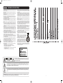
cm203_face.qxd
6/9/06
5:37 PM
Page 1
CM.203
DUAL TABLETOP CD PLAYER WITH MIXER
USER MANUAL
cm203_face.qxd
6/9/06
5:37 PM
Page 2
IMPORTANT SAFETY INSTRUCTIONS
1. Read Instructions – All the safety and operating instructions should be read before
this product is operated.
2. Retain Instructions – The safety and operating instructions should be retained for
future reference.
3. Heed Warnings – All warnings on the appliance and in the operating instructions
should be adhered to.
4. Follow Instructions – All operating and use instructions should be followed.
5. Water and Moisture – The appliance should not be used near water - for example, near a bathtub, washbowl, kitchen sink, laundry tub, in a wet basement, or
near a swimming pool, and the like.
6. Wall or Ceiling Mounting – The product should be mounted to a wall or ceiling only
as recommended by the manufacturer.
7. Heat – Appliance should be situated away from heat sources such as radiators,
heat registers, stoves, or other appliances (including amplifiers) that produce
heat.
8. Power Sources – This product should be operated only from the type of power
source indicated on the rating label. If you are not sure of the type of power supply to your home, consult your product dealer or local power company. For products intended to operate from battery power, or other sources, refer the operating instructions.
9. Grounding or Polarization – This product may be equipped with a polarized alternation-current line plug (a plug having one blade wider than the other). This plug
will fit into the power outlet only one way. This is a safety feature. If you are
unable to insert the plug fully into the outlet, try reversing the plug. If the plug
should still fail to fit, contact your electrician to replace your obsolete outlet. Do
not defeat the safety purpose of the polarized plug.
10. Power-Cord Protection –Power-supply cords should be routed so that they are
not likely to be walked on or pinched by items placed upon or against them, paying particular attention to the cord in correspondence of plugs, convenience
receptacles, and the point where they exit from the appliance.
11. Cleaning - The appliance should be cleaned only as recommended by the manufacturer. Clean by wiping with a cloth slightly damp with water. Avoid getting
water inside the appliance.
12. For AC line powered units - Before returning repaired unit to user, use an ohmmeter to measure from both AC plug blades to all exposed metallic parts. The
resistance should be more than 100,000 ohms
13. Non-use Periods –The power cord of the appliance should be unplugged from
the outlet when left unused for a long period of time.
14. Object and Liquid Entry – Care should be taken so that objects do not fall and
liquids are not spilled into the enclosure through openings
15. Damage Requiring Service – The appliance should be serviced by qualified service personnel when:
A. The power-supply cord or the plug has been damaged; or
B. Objects have fallen, or liquid has been spilled into the appliance; or
C. The appliance has been exposed to rain; or
D. The appliance does not appear to operate normally or exhibits a marked
change in performance; or
E. The appliance has been dropped, or the enclosure is damaged.
CAUTION
RISK OF ELECTRIC SHOCK
DO NOT OPEN
16. Servicing – Do not attempt any service to the appliance beyond that described
in the operating instructions. All other servicing should be referred to qualified
service personnel.
17. Ventilation – Slots and openings in the cabinet are provided for ventilation and
to ensure reliable operation of the product and to protect it from overheating, and
these openings must not be blocked or covered. The openings should never be
blocked by placing the product on a bed, sofa, rug, or other similar surface. This
product should not be placed in a built-in installation such as a bookcase or rack
unless proper ventilation is the manufacturer’s instructions have been adhered
to.
18. Attachments – do not use attachments not recommended by the manufacturer
as they may cause hazards.
19. Accessories – Do not place this product on an unstable cart, stand, tripod, bracket, or table. The product may fall, causing serious injury to a child or adult, and
serious damage to the product. Use only with a cart, stand, tripod, bracket, or
table recommended by the manufacturer, or sold with the product. Any mounting
of the product should follow the manufacturer’s instructions, and should use a
mounting accessory recommended by the manufacturer.
20. Lightning – For added protection for this product during a lightning storm, or
when it is left unattended and unused for long periods of time, unplug it from the
wall outlet and disconnect the antenna or cable system. This will prevent damage to the product due to lightning and power-line surges.
21. Replacement Parts – When replacement parts are required, be sure the service
technician has used replacement parts specified by the manufacturer or have
the same characteristics as the original part. Unauthorized substitutions may
result in fire, electric shock, or other hazards.
22. Safety Check – Upon completion of any service or repairs to
this product, ask the service technician to perform safety
checks to determine that the product is in proper operating
condition.
23.This product is in compliance with EU WEEE regulations.
Disposal of end of life product should not be treated as
municipal waste. Please refer to your local regulations for
instructions on proper disposal of this product.
24. Carts and Stands – The appliance should be used only with
a cart or stand that is recommended by the manufacturer. An
appliance and cart combination should be moved with care.
Quick stops, excessive force, and uneven surfaces may
cause the appliance and cart combination to overturn.
25. This device complies with Part 15 of the FCC Rules. Operation is subject to the
following two conditions: (1) this device may not cause harmful interference,
and (2) this device must accept any interference received, including interference
that may cause undesired operation.”
CAUTION: To reduce the risk of electric shock, do not remove any
cover. No user-serviceable parts inside. Refer servicing to qualified service personnel only.
The lightning flash with arrowhead symbol within the equilateral triangle is intended to alert the user
to the presence of un-insulated “dangerous voltage” within the product’s enclosure that may be of sufficient magnitude to constitute a risk of electric shock.
The exclamation point within the equilateral triangle is intended to alert the user to the presence of
important operation and maintenance (servicing) instructions in the literature accompanying this appliance.
CAUTION: To prevent electric shock, do not use this polarized plug with an extension cord, receptacle or other outlet unless the blades can be fully inserted to prevent blade exposure.
11
cm203_face.qxd
6/9/06
5:37 PM
Page 3
WARRANTY & RETURN POLICY
Warranty
Through Stanton’s authorized dealers around the World, Stanton, or one of Stanton’s authorized distributors outside the U.S., will, without charge, repair
or replace, at the sole discretion of the entity responsible for making the repair or providing the replacement, any Stanton merchandise proved defective
in material or workmanship for a period of one (1) year following the date of original purchase. Exceptions to this warranty are as noted below:
The warranty for mechanical parts which are subject to wear and tear are limited to the earlier to occur of thirty (30) days following the date of original
purchase or the following number of cycles: Faders - 15,000; Rotary potentiometers - 10,000; and Switches - 10,000.
Stanton will warrant all replacement parts and repairs for ninety (90) days from the date of original shipment. Repairs made necessary by reason of misuse, alteration, normal wear, or accident are not covered under this warranty.
Returns
Authorized Stanton dealers are only authorized to sell and distribute merchandise within a specific country. All goods requiring warranty repair or replacement must be returned (freight prepaid if not hand-delivered) to the authorized Stanton dealer from whom the merchandise was purchased and in the
same country where the merchandise was purchased. For purposes of purchases made via the Internet, the merchandise must be returned to the authorized Stanton dealer in the country where the authorized Stanton dealer which sold the merchandise to purchaser is located and not the authorized Stanton
dealer in the country where the purchaser is located or the country in which the merchandise was received. Any returns to a non-authorized dealer or to
an authorized Stanton dealer not in the same country as the merchandise was intended to be sold or as set forth above will void this warranty.
To initiate a warranty repair, you must contact the authorized Stanton dealer from whom you purchased the merchandise, and follow such authorized
Stanton dealer’s return policy.
Stanton assumes no risk and shall be subject to no liability for damages or loss resulting from the specific use or application made of the merchandise.
Stanton’s liability for any claim, whether based on breach of contract, negligence, infringement of any rights of any party, or product liability, and relating
to the merchandise shall not exceed the price received by Stanton from your purchase of such merchandise. In no event will Stanton be liable for any
special, incidental or consequential damages (including loss of use, loss of profit and claims of third parties) however caused, whether by the negl gence
of Stanton or otherwise. To the extent permitted by law and except as otherwise provided above, Stanton disclaims any express or implied warranties of
merchantability or fitness for a particular purpose.
The above warranty provides you with specific legal rights. You may also have additional rights, which are subject to variation from state to state and
country to country.
If there is a dispute regarding the warranty of merchandise that does not fall under the warranty conditions stated above, please include a written explanation with the merchandise when returned pursuant to the terms and conditions set forth herein.
Please register your product online at www.stantondj.com or mail your completed warranty card to:
Stanton Magnetics, Inc, 3000 SW 42 St. Hollywood, Florida 33312.
INTRODUCTION
The CM.203 is the perfect CD mixer for the DJ looking for simplicity backed by professional quality. This versatile unit features dual top loading CD players and built-in line inputs for your iPod® and other portable media devices so you can easily access a variety of music sources! The CM.203 makes it
easy to please the crowd in virtually any venue, from clubs, bars and restaurants to dance studios and mobile gigs.
FEATURES
CD Section:
Up to 8% pitch control with pitch bend
Fader start
Relay play
Mixer Section
2 line inputs to connect iPod®, other MP3 device or more CD players
Gain and 3 band EQ (+9/-26) per channel
User replaceable cross fader
1/4" mic input with volume control
Headphone output with cue pan
SETUP
Checking the Contents of Package
Check that the carton contains the following items:
(1) CM.203 CD Mixer
(2) Two (2) rack ears
(3) Eight (8) screws
(4) AC Power Cord
(5) Owner’s Manual (this book)
(6) RCA to mini-jack cable for iPod®, computers or other MP3 players or CD players
(7) Stanton product guide
***iPod® is a registered trademark for Apple Computer, Inc.
10
3
cm205_face.qxd
6/9/06
5:38 PM
Page 4
INSTALLING THE RACK EARS
• Installing the Rack Ears
:: STEP 1 ::
Place the unit upside down over a pad, pillow, or towel to avoid damaging the control surface.
SPECIFICATIONS
MIXER SECTION
FREQUENCY RESPONSE (Line to Master Output)
THD+N (Line)
S/N RATIO: REF TO MAX OUTPUT LEVEL (Dynamic Range)
Noise Floor (Line Input to Any Output) (Unbalanced Out)
CROSS TALK (Line to Line,Phono to Line,Line to Phono)
CHANNEL FADER KILL
CROSS FADER KILL
Channel EQ
20 Hz to 20 kHz +/- 2 dB
<0.01% at 1 kHz
>90 dB
< -85 dBV
< -85 dB @ 1 kHz
< -85 dB @ 1 kHz
< -75 dB @ 1 kHz
Hi
+9 dB, -16dB @13HZ
Mid +9 dB, -23dB @1HZ
Low +9 dB, -23dB @70HZ
CD SECTION
:: STEP 2 ::
Align the left rack ear with the screw holes as shown. Use 4 screws to lock the ear in place.
FREQUENCY RESPONSE (CD to Master Output)
THD+N WITH 20 KHZ LOW PASS FILTER
S/N RATIO:( ref Full-Scale)
20 Hz to 20 kHz +/- 2.0 dB
0.05% at 1 kHz
>85 dB
MICROPHONE
FREQUENCY RESPONSE (Mic to Master Output)
THD+N With 20 kHz Low Pass Filter
Mic EIN:
20 Hz to 20 kHz +/- 2.0 dB
0.05% at 1 kHz
>110 dBV
INPUT/OUTPUT
LINE INPUTS
MIC INPUT
MASTER OUTPUT
RECORD OUTPUT
HEADPHONE OUTPUT
:: STEP 3 ::
Repeat step 2 with the right rack ear. You can now turn the unit over.
2 x Stereo RCA -14 dBV/nominal input level 18 k Ohm unbalanced
1x TRS -54 dBV/nominal input level 10k Ohm Balanced
2x RCA unbalanced nominal load 10k Ohms
2x RCA unbalanced -10dBV into 10k ohm load
1x 1/4” Phone Jack Max Load 33 Ohms
1x 1/8” Mini Phone Jack
GENERAL
SYSTEM
DISC LOADING
DISPLAY
PITCH CONTROL RANGE
PITCH BEND
PITCH ACCURACY
Compact Disc Digital Audio
Top Loading
11 Digit LCD Display
Within +/- 8%
+/- 8%
+/-0.15%
PHYSICAL SPECIFICATIONS
DIMENSIONS
WEIGHT (UNIT)
OPERATING TEMPERATURE
STORAGE TEMPERATURE
POWER SOURCE
440 (W) x 266(D) x110.5(H) mm
4.4 Kgs.
0 ºC to 40 ºC
-20 ºC to 50 ºC
US: 120V, 60Hz, AC 23W
EU: 230V, 50Hz, AC 23W
UK: 240V, 50Hz, AC 23W
JPN:100V, 50/60Hz, AC 23W
AUS:240V, 50Hz, AC 23W
ARG:220V, 50Hz, AC 23W
REPLACEMENT PARTS
Contact your local reseller to order replacement parts.
4
9
cm203_face.qxd
6/9/06
5:37 PM
Page 5
REAR PANEL FUNCTIONS
QUICK SETUP DIAGRAM
33. POWER SWITCH – Turns unit off and on. Note*** Remember to turn
ALL volume levels down when turning on/off the unit.
34. AC INPUT – This is the connection for the supplied power cable.
Study this setup diagram. Make sure all faders are at "zero" and all devices are off. First, connect all input sources and processors. Next, connect your
microphone and monitor headphones. Finally, connect the stereo outputs to the power amplifier(s) and/or audio receivers. Additionally, you can connect
the REC output to any recording device such as a CD or DVD recorder. Plug your mixer into AC power. Now you are ready to switch everything on.
IMPORTANT: Always switch on your audio input sources such as turntables or CD players first, then your mixer, and finally any amplifiers. When turning
off, always reverse this operation by turning off amplifiers, then your mixer, and then input devices.
35. MASTER OUTPUT – Unbalanced RCA connectors controlled by the
Master level.
36. REC OUTPUT – Unbalanced RCA jacks used to send the output of
the program to any connected recording device.
37. LINE INPUTS – Unbalanced RCA jacks for connecting stereo audio
from line level sources such as CD players, DVD, MP3 players can be
connected using the included RCA cable.
NOTE: Plug mono audio sources into both Left and Right inputs using
a "Y" cable connector.
38. MIC INPUT – Insert your Microphone with 1/4 ” plug here.
8
5
cm203_face.qxd
6/9/06
5:37 PM
Page 6
CD PLAYER FUNCTIONS
LCD DISPLAY FUNCTIONS
16. FRAMES – The CD Player breaks down a second into 75 frames for
accurate cueing. This shows the frames elapsed or remaining
depending on mode setting.
17. TOTAL REMAIN – Displays the total remaining time for the entire
disc.
18. REMAIN – Displays the remaining time for the current track.
19. PITCH – Shows the percentage change in pitch.
20. TIME BAR – This bar gives a visual approximation of a track’s or
disc’s remaining time. This bar will begin to flash when a CD or a track
is ending.
21. SINGLE – Shows when the unit is set to play just one track at a time.
When this is not lit, the CD will play continuously through all tracks.
This function is controlled by the SING/CONT button.
13. TRACK – Shows the current track that the unit is playing.
14. MINUTES – Shows the minutes elapsed or remaining depending on
mode setting.
15. SECONDS – Shows the seconds elapsed or remaining depending on
mode setting.
MIXER FUNCTIONS
22. INPUT TOGGLE SWITCH – Switches the input source between the
internal CD decks and the line inputs.
23. CHANNEL GAIN –Adjusts the pre-fader volume for cleaner sound.
27
7. CUE – Used to recall and preview cue points. A new cue point is set
every time playback is resumed.
1. EJECT – Opens the CD door.
2. FADER START – You can use the crossfader to start and stop the CD
decks. The fader start switch activates the fader start feature. When in
the ON position, sliding the crossfader to either end will start the CD
on that side and pause the CD on the other side and return to the cue
point. Fader Start always starts from the cue point.
22
24. CHANNEL EQ – Adjusts the high, mid and low frequency levels of
each channel.
23
25. INPUT FADER – Controls individual source levels (channels) in the
mix.
8. SEARCH – Scans forward or back through the current track. This unit
features four scan speeds. Keep the or
button held for a few seconds to scan faster. Tap the button for frame search.
9. PLAY/PAUSE – Plays or pauses the CD. A new cue point is set every
time playback is resumed.
3. TIME – LCD display reads the time remaining or time elapsed, according to this button.
4. HEADPHONE INPUT – Insert either 1/8” or 1/4” plug for your headphones here.
10. PITCH BEND – Used to momentarily speed up or down the track. The
maximum pitch range is up to +/- 8% from pitch setting.
5. SGL/CTN – Switches between Single or Continuous play mode.
11. PITCH FADER – Used to speed up or slow down current track. The
maximum pitch range is up to +/-8%.
6. TRACK – Used to select the track to be played. The +10 button skips
10 tracks at a time.
12. LCD DISPLAY – Shows time (minutes, seconds, frame), and pitch
information.
26. REPLACEABLE CROSSFADER – Achieves clean transitions
between the two input channels. "Hard left" selects Channel 1. "Hard
right" selects Channel 2. With the crossfader centered, both channels
are live. Use the crossfader for fast and seamless fades from one
channel to the other.
Note: The crossfader is user replaceable in case of failure. Simply
unscrew the two large screws that hold it in place, lift it out and disconnect its cable. Re-attach the new crossfader and screw the
mounting plate back onto the unit - you’re back in business!
28
29
24
30
27. RELAY –Set both sides of the CD player to single mode on the control. When Disc 1 ends the CD player will automatically change to
Disc 2 and when Disc 2 ends it will return to Disc 1.
31
28. MIC INPUT GAIN – Adjusts the microphone input level.
29. MASTER LEVEL – Controls the overall output level.
25
30. HEADPHONE LEVEL – Adjusts the cue volume.
32
31. CHANNEL CUE SELECTOR – Used to route channel audio to your
headphones.
32. LEVEL INDICATORS – The dual LEDs indicators are used to indicate
the pre-fader level of channels 1 and 2.
26
6
7
cm203_face.qxd
6/9/06
5:37 PM
Page 5
REAR PANEL FUNCTIONS
QUICK SETUP DIAGRAM
33. POWER SWITCH – Turns unit off and on. Note*** Remember to turn
ALL volume levels down when turning on/off the unit.
34. AC INPUT – This is the connection for the supplied power cable.
Study this setup diagram. Make sure all faders are at "zero" and all devices are off. First, connect all input sources and processors. Next, connect your
microphone and monitor headphones. Finally, connect the stereo outputs to the power amplifier(s) and/or audio receivers. Additionally, you can connect
the REC output to any recording device such as a CD or DVD recorder. Plug your mixer into AC power. Now you are ready to switch everything on.
IMPORTANT: Always switch on your audio input sources such as turntables or CD players first, then your mixer, and finally any amplifiers. When turning
off, always reverse this operation by turning off amplifiers, then your mixer, and then input devices.
35. MASTER OUTPUT – Unbalanced RCA connectors controlled by the
Master level.
36. REC OUTPUT – Unbalanced RCA jacks used to send the output of
the program to any connected recording device.
37. LINE INPUTS – Unbalanced RCA jacks for connecting stereo audio
from line level sources such as CD players, DVD, MP3 players can be
connected using the included RCA cable.
NOTE: Plug mono audio sources into both Left and Right inputs using
a "Y" cable connector.
38. MIC INPUT – Insert your Microphone with 1/4 ” plug here.
8
5
cm205_face.qxd
6/9/06
5:38 PM
Page 4
INSTALLING THE RACK EARS
• Installing the Rack Ears
:: STEP 1 ::
Place the unit upside down over a pad, pillow, or towel to avoid damaging the control surface.
SPECIFICATIONS
MIXER SECTION
FREQUENCY RESPONSE (Line to Master Output)
THD+N (Line)
S/N RATIO: REF TO MAX OUTPUT LEVEL (Dynamic Range)
Noise Floor (Line Input to Any Output) (Unbalanced Out)
CROSS TALK (Line to Line,Phono to Line,Line to Phono)
CHANNEL FADER KILL
CROSS FADER KILL
Channel EQ
20 Hz to 20 kHz +/- 2 dB
<0.01% at 1 kHz
>90 dB
< -85 dBV
< -85 dB @ 1 kHz
< -85 dB @ 1 kHz
< -75 dB @ 1 kHz
Hi
+9 dB, -16dB @13HZ
Mid +9 dB, -23dB @1HZ
Low +9 dB, -23dB @70HZ
CD SECTION
:: STEP 2 ::
Align the left rack ear with the screw holes as shown. Use 4 screws to lock the ear in place.
FREQUENCY RESPONSE (CD to Master Output)
THD+N WITH 20 KHZ LOW PASS FILTER
S/N RATIO:( ref Full-Scale)
20 Hz to 20 kHz +/- 2.0 dB
0.05% at 1 kHz
>85 dB
MICROPHONE
FREQUENCY RESPONSE (Mic to Master Output)
THD+N With 20 kHz Low Pass Filter
Mic EIN:
20 Hz to 20 kHz +/- 2.0 dB
0.05% at 1 kHz
>110 dBV
INPUT/OUTPUT
LINE INPUTS
MIC INPUT
MASTER OUTPUT
RECORD OUTPUT
HEADPHONE OUTPUT
:: STEP 3 ::
Repeat step 2 with the right rack ear. You can now turn the unit over.
2 x Stereo RCA -14 dBV/nominal input level 18 k Ohm unbalanced
1x TRS -54 dBV/nominal input level 10k Ohm Balanced
2x RCA unbalanced nominal load 10k Ohms
2x RCA unbalanced -10dBV into 10k ohm load
1x 1/4” Phone Jack Max Load 33 Ohms
1x 1/8” Mini Phone Jack
GENERAL
SYSTEM
DISC LOADING
DISPLAY
PITCH CONTROL RANGE
PITCH BEND
PITCH ACCURACY
Compact Disc Digital Audio
Top Loading
11 Digit LCD Display
Within +/- 8%
+/- 8%
+/-0.15%
PHYSICAL SPECIFICATIONS
DIMENSIONS
WEIGHT (UNIT)
OPERATING TEMPERATURE
STORAGE TEMPERATURE
POWER SOURCE
440 (W) x 266(D) x110.5(H) mm
4.4 Kgs.
0 ºC to 40 ºC
-20 ºC to 50 ºC
US: 120V, 60Hz, AC 23W
EU: 230V, 50Hz, AC 23W
UK: 240V, 50Hz, AC 23W
JPN:100V, 50/60Hz, AC 23W
AUS:240V, 50Hz, AC 23W
ARG:220V, 50Hz, AC 23W
REPLACEMENT PARTS
Contact your local reseller to order replacement parts.
4
9
cm203_face.qxd
6/9/06
5:37 PM
Page 3
WARRANTY & RETURN POLICY
Warranty
Through Stanton’s authorized dealers around the World, Stanton, or one of Stanton’s authorized distributors outside the U.S., will, without charge, repair
or replace, at the sole discretion of the entity responsible for making the repair or providing the replacement, any Stanton merchandise proved defective
in material or workmanship for a period of one (1) year following the date of original purchase. Exceptions to this warranty are as noted below:
The warranty for mechanical parts which are subject to wear and tear are limited to the earlier to occur of thirty (30) days following the date of original
purchase or the following number of cycles: Faders - 15,000; Rotary potentiometers - 10,000; and Switches - 10,000.
Stanton will warrant all replacement parts and repairs for ninety (90) days from the date of original shipment. Repairs made necessary by reason of misuse, alteration, normal wear, or accident are not covered under this warranty.
Returns
Authorized Stanton dealers are only authorized to sell and distribute merchandise within a specific country. All goods requiring warranty repair or replacement must be returned (freight prepaid if not hand-delivered) to the authorized Stanton dealer from whom the merchandise was purchased and in the
same country where the merchandise was purchased. For purposes of purchases made via the Internet, the merchandise must be returned to the authorized Stanton dealer in the country where the authorized Stanton dealer which sold the merchandise to purchaser is located and not the authorized Stanton
dealer in the country where the purchaser is located or the country in which the merchandise was received. Any returns to a non-authorized dealer or to
an authorized Stanton dealer not in the same country as the merchandise was intended to be sold or as set forth above will void this warranty.
To initiate a warranty repair, you must contact the authorized Stanton dealer from whom you purchased the merchandise, and follow such authorized
Stanton dealer’s return policy.
Stanton assumes no risk and shall be subject to no liability for damages or loss resulting from the specific use or application made of the merchandise.
Stanton’s liability for any claim, whether based on breach of contract, negligence, infringement of any rights of any party, or product liability, and relating
to the merchandise shall not exceed the price received by Stanton from your purchase of such merchandise. In no event will Stanton be liable for any
special, incidental or consequential damages (including loss of use, loss of profit and claims of third parties) however caused, whether by the negl gence
of Stanton or otherwise. To the extent permitted by law and except as otherwise provided above, Stanton disclaims any express or implied warranties of
merchantability or fitness for a particular purpose.
The above warranty provides you with specific legal rights. You may also have additional rights, which are subject to variation from state to state and
country to country.
If there is a dispute regarding the warranty of merchandise that does not fall under the warranty conditions stated above, please include a written explanation with the merchandise when returned pursuant to the terms and conditions set forth herein.
Please register your product online at www.stantondj.com or mail your completed warranty card to:
Stanton Magnetics, Inc, 3000 SW 42 St. Hollywood, Florida 33312.
INTRODUCTION
The CM.203 is the perfect CD mixer for the DJ looking for simplicity backed by professional quality. This versatile unit features dual top loading CD players and built-in line inputs for your iPod® and other portable media devices so you can easily access a variety of music sources! The CM.203 makes it
easy to please the crowd in virtually any venue, from clubs, bars and restaurants to dance studios and mobile gigs.
FEATURES
CD Section:
Up to 8% pitch control with pitch bend
Fader start
Relay play
Mixer Section
2 line inputs to connect iPod®, other MP3 device or more CD players
Gain and 3 band EQ (+9/-26) per channel
User replaceable cross fader
1/4" mic input with volume control
Headphone output with cue pan
SETUP
Checking the Contents of Package
Check that the carton contains the following items:
(1) CM.203 CD Mixer
(2) Two (2) rack ears
(3) Eight (8) screws
(4) AC Power Cord
(5) Owner’s Manual (this book)
(6) RCA to mini-jack cable for iPod®, computers or other MP3 players or CD players
(7) Stanton product guide
***iPod® is a registered trademark for Apple Computer, Inc.
10
3