1
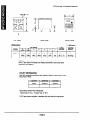
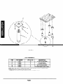
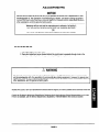
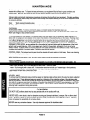
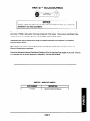
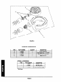
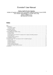
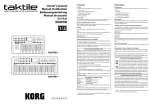
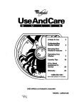
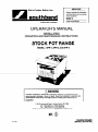
IMPORTANT
FOR FUTURE REFERENCE
Please complete this information
and retain this manual for the life
of the equipment.
MODEL #
SERIAL #
DATE PURCHASED
OPERATOR’S MANUAL
INSTALLATION
OPERATION AND MAINTENANCE
INSTRUCTIONS
STOCK POT RANGE
MODEL:
SPR-1, SPR-2, and SPR-3
Improper installation, adjustment, alteration, service, or maintenance can
cause property damage, injury or death. Read the installation, operation and
maintenance instructions thoroughly before installing and operating this
equipment.
1100
Old Honeycutt Road . Fuquay-Varina, NC 27526
4
Fax
(919)552-9161
(800) 625-6143
.(800)348-2558
l (919)
552-9798
Middleby Corp. Service Hot Line (800)238 8444 (after hours)
$18.00
COUNTER STEAMER
(MANUAL SECTION SR)
SAFETY PRECAUTIONS
Before installing and operating this equipment, be sure everyone involved in its operation is fully trained and aware of precautions. Accidents and problems can be caused by failure to follow fundamental rules and precautions.
The following symbols, found throughout this manual, alert you to potentially dangerous conditions to the operator, service
personnel, or to the equipment.
1A
DANGER
1A
WARNING]
1
This symbol warns of immediate hazards which will result in severe injury or death.
This symbol refers to a potential hazard or unsafe practice which could result in injury or
death.
This symbol refers to a potential hazard or unsafe practice which could result in injury,
product, or property damage.
1
NOTICE
1
This symbol refers to information that needs special attention or must be fully understood,
even though not dangerous.
POST IN PROMINENT LOCATION
The emergency telephone
gas odor is detected.
number of your gas supplier and instructions to follow if
A DANGER
EXPLOSION HAZARD
If a gas odor is detected, shut down equipment at the main shut-off valve.
Immediately call the emergency phone number of your gas supplier.
A FOR YOUR SAFETY
Do not store or use gasoline or other flammable vapors and liquids in the vicinity of
this or any other appliance.
I
Keep area around appliances
free and clear of combustibles.
n
! WARNING
Asphyxiation
can result from improper ventilation. Do not obstruct the flow of
combustion and ventilation air to and from your cooking equipment.
Be sure the Operators
Manual and important papers are given to the proper authority
to retain for future reference.
I
Congratulations!
You have purchased one of the finest pieces of heavy-duty
commercial
cooking equipment
on the market.
You will find that your new equipment, like ail Southbend equipment, has been designed and manufactured to meet the toughest standards in the industry. Each piece of Southbend equipment is carefully engineered and designs are verified through
laboratory tests and field installations. With proper care and field maintenance, you will experience years of reliable, troublefree operation. For best results, read this manual carefully.
RETAIN THIS MANUAL
FOR FUTURE
REFERENCE.
TABLE OF CONTENTS:
Safety Precautions.. ................................................................................................................
inside front cover
2
Specifications ...................................................................................................................................................
3-7
Installation .....................................................................................................................................................
6
Operation ..........................................................................................................................................................
Adjustments.. ...................................................................................................................................................
.9
Maintenance.. .................................................................................................................................................
10
Parts/Accessories.. ...................................................................................................................................
1 l-l 6
17
Warranty .........................................................................................................................................................
Location of serial and identification
plates:
The serial plate with all the specifications is located at the rear of the unit on back panel. Reference part number 1179452 in
parts section “main body components” of this manual. There is also a product identification plate that has only the model and
serial number attached to the front upper right comer of the valve control panel.
Read these instructions carefully before attempting installation. “Installation” and u Start Up” should be performed by a qualified installer. Unless the installation instructions for the above-described
Southbend product are followed and performed by a
qualified service technician (a person experienced in and knowledgeable
with the installation of commercial gas and/or electric cooking equipment) then the terms and conditions of the Manufacturer’s
Limited Warranty will be rendered void and no
warranty of any kind shall apply.
In the event you have questions concerning the installation, use, care, or service of the product, write to the Technical Service
Department, Southbend, 1100 Old Honeycutt Road., Fuquay-Varina,
North Carolina 27526.
NOTICE
This product
is intended
IMMEDIATELY
for commercial
INSPECT
use only; not for household
FOR SHIPPING
use.
DAMAGE
All containers should be examined for damage before and during unloading. The freight carrier has
responsibility
for its safe transit and delivery.
If damaged equipment
is received,
either
apparent or concealed, a claim must be made with the delivering carrier.
assumed
A) Apparent damage or loss must be noted on the freight bill at the time of delivery. The freight bill must
then be signed by the carrier representative (Driver). If the bill is not signed, the carrier may refuse
the claim. The carrier can supply the necessary forms.
B) A request for inspection must be made to the carrier within 15 days if there is concealed damage or
The carrier should arrange an inspecloss that is not apparent until after the equipment is uncrated.
tion. Be certain to hold all contents plus all packing material.
FbsthGada&&dtmLau
1100 Old Honeycutt
Road
Fuquay-Varina,
NC 27526
4
(919) 552-9161
f
i6OOj 346-2556
FAX(Q19)
625-6143
FAX(919)
552-9798
sout hbend
A MIDDLEBY COMPANY
PAGE 1
NOTE: Not for Scale.
For Dimensional
Purposes Only.
G
-+-
f
T
D
B
E
i
$
C
SIDE VIEW
TOP VIEW
FRONT VIEW
Dimensions:
( ) = Millimeters
NOTE: Above dimensions are for single Stock Pot Ranges. SPR-2 Double and
SPR-3 Triple Stock Pot Ranges are shipped assembled at factory and above
dimensions are different.
UTILITY
INFORMATION:
One 3/4” connection
tery of two or three.
required for each individual
Range or each range in a bat-
REQUIRED OPERATING PRESSURE:
Natural Gas 4” W.C.; Propane Gas 10” W.C.
A 314” gas pressure
regulator is standard
PAGE 2
with each stock pot range section.
NOTICE
Southbend reserves the right to change specifications and product design without notice. Such
revisions do not entitle the buyer to corresponding changes, improvements, additions, or replacements
for previously purchased equipment.
NOTICE
These procedures must be followed by qualified personnel or warranty will be void.
GENERAL:
NOTICE
The unit, when installed, must conform with local codes, or in the absence of local codes, with the
National Fuel Gas Code, ANSI 2223.1 -latest edition.
GAS CONNECTION:
The Serial Plate is located at the rear of the unit on the back panel. It indicates the type of gas the unit is equipped to
burn.
All Southbend equipment
on serial plate.
is adjusted at the factory but may need a finish adjustment once installed.
These models are design-certified
This appliance
Check type of gas
for operation on natural or propane gases.
should be connected ONLY to the type of gas for which it is equipped.
Add supply requirement, i.e. pipe size, pressure regulator infomation,
when all units on line are operating simultaneously.
operating pressure WC - natural and propane
An adequate gas supply is imperative. Undersized or low pressure lines will restrict the volume of gas required for satFluctuations of more than 25% on natural gas or 10% on propane gas will create problems and
isfactory performance.
affect burner operating characteristics.
A l/3” pressure tap is located on the manifold to measure the manifold pressure.
An adequate gas supply line to the unit should be no smaller than the I.D. of the pipe from the unit to which it is connected.
Purge the supply line to clean out dust, dirt, or other foreign matter before connecting the line to the unit.
All pipe joints and connections must be tested thoroughly for gas leaks. Use only soapy water for testing on all gases.
NEVER use an open flame to check for gas leaks. All connections must be checked for leaks after the unit has been
put into operation. Test pressure should not exceed l/4” W.C.
For Natural gas the regulator is set to deliver a 4” W.C. pressure to the manifold.
IO” W.C.
A!
This appliance
For Propane gas it is set to deliver
CAUflON
and its individual shutoff valve must be disconnected
from the gas supply piping sys-
tem during any pressure testing of that system at test pressures in excess of1/2 PSIG (3.45 KPA).
This appliance
must be isolated from the gas supply piping system by closing its individual manual
shutoff valve during any pressure testing of the gas supply piping system at test pressure equal to or
less than 112 PSIG (3.45KPA).
PAGE 3
If this equipment is being installed at over 2,000 feet altitude and was not specified on order, contact the appropriate
authorized Southbend Service Representative or the Southbend Service Department. Failure to install with proper orifice sizing will result in improper performance and may void the warranty.
NOTICE
If applicable, the vent line from the gas appliance pressure regulator should be installed to the outdoors
in accordance with local codes or, in the absence of local codes, with the National Fuel Gas Code, ANSI
2223. 1-latest edition.
CLEARANCES:
Minimum Clearances -- Inches (mm)
From Combustible
Construction
From Non-Combustible
Construction
8 inches
0
0
0
Back
Right Side
Left Side
Floor
NOTE: For use in noncombustible locations a.
All units must be installed in such a manner that the flow of combustion and ventilation air are not obstructed.
Provisions for an adequate air supply must be provided. Do not obstruct the front or rear of the unit, as combustion air
enters through this area. Be sure to inspect and clean the ventilation system according to the ventilation equipment
manufacturers instructions.
No additional clearance from the sides and back is required for service as the units are serviceable from the front.
DO NOT MOUNT ABOVE OTHER COOKING EQUIPMENT.
NOTICE
Local codes regarding installation vary greatly from one area to another. The National Fire
Protection Association,
Inc. states in its NFPA 96 latest edition that local codes are the “authority
having jurisdiction”
when it comes to installation requirements for equipment. Therefore,
installations should comply with all local codes.
EXHAUST FANS AND CANOPIES: c anopies are set over ranges, ovens, etc., for ventilation purposes. It is
recommended that a canopy extend 6” past the appliance and the bottom edge be located 6’6” from the floor. Filters
should be installed at an angle of 45 degrees or more from horizontal. This position prevents dripping grease and facilitates collecting the run-off grease in a drip pan, usually installed with a filter. A strong exhaust fan tends to create a
vacuum in the room and may interfere with burner performance or may extinguish pilot flames. Fresh air openings
approximately equal to the fan area will relieve such a vacuum.
WALL EXHAUST
FAN: The exhaust fan should be installed at least 2” above the vent opening at the top of the
unit.
In case of unsatisfactory performance on any appliance, check the appliance with the exhaust fan in the “OFF” position.
Do this only long enough to check equipment performance. Then turn hood back on and let it run to remove any
exhaust that may have accumulated during the test.
PAGE 4
I
NOTICE
I
Proper ventilation is the owner’s responsibility.
covered by warranty.
A
I
Any problem due to improper ventilation
I
will not be
I
WARNING
improper ventilation can result in personal injury or death. Ventilation which fails to properly remove
flue products can cause headaches, drowsiness, nausea, or could result in death.
LEVELING:
Unit must be level to assure maximum performance.
TO INSTALL
1. Remove
2. Shipped
Improper leveling may void warranty.
STOCK POT RANGE:
unit from packaging.
with every unit should be a leg package
containing four legs. Two of which will have flanges for bolting
them to the floor. These legs are to be installed on the rear of the unit. These are labeled (Item “E”) in figure 1.
The other adjustable legs are to be installed on the front of the unit.
3. Leg pads (Item “C”) in figure 1 have already been installed on the bottom of the unit. To install legs simply screw
legs into leg pads on bottom of unit.
4. Once the unit has been moved into position adjust front and rear adjusters in bottom of legs until unit is level.
Make sure unit is leveled front to back and side to side. It is very important that this unit be level.
5. Once the unit has been leveled attach the flanged feet to the floor using appropriate fasteners.
NOTICE
This unit MUST be attached to the floor by means of the flanged feet at the rear of the unit. Failure to
do so may create a tip hazard which could result in injury to the operator or damage to the unit. Failure
to install properly will void the manufacturer’s warranty.
PAGE 5
FIGURE 1
LEG ASSEMBLY
NOTE: Items A, B, and C are installed at the factory. items D and E are to be installed
Flanged feet (item E) must go on to the rear of the unit.
* 1179510 is a leg package consisting of 2 standard legs and 2 flanged legs.
PAGE 6
in field.
PERFORMANCE CHECK:
The following items should be checked within the first 30 days of operation
by a qualified
service technician.
1. Verify equipment is level.
2. Check ventilation.
3. Check timers, switches and motor for proper installation and operation.
4. Check for any damage to unit from shipping or installation.
5. Check for proper clearance from combustible
materials.
6. Verify proper type of gas
7. Verify gas supply and pressure (pressure regulator is already installed
at factory.)
8. Check gas connection and check for leaks.
It is common for new products to require a burn-off time to dry out insulation
PAGE 7
and metal cooking surfaces.
THEORY
TO LIGHT STANDING
OF OPERATION
PILOT:
1. Locate pilot adjustment screw. This is located between the burner valves and is accessable
through the slotted hole in the control panel.
2. Verify the gas supply line is connected and gas is being supplied to the unit.
3. Light pilot and verii that the pilot flame is approximately l/4 “ high.
4. If pilot is too low turn pilot adjustment screw counter clockwise to increase the pilot flame. If
pilot is too high turn pilot adjustment screw clockwise to lower pilot flame.
A CAUTION
To eliminate aas buildup which could result in exolosion:
In the event of main burner ignition failure, a five minute purge period with gas controls in the “off”
position must be observed prior to restablishing ignition source.
A DANGER
EXPLOSION HAZARD
In the event a gas odor is detected, shut down equipment at the main shut off valve. Immediately call
the emergency phone number of your gas supplier.
A WARNING
BURN OR EXPLOSION
HAZARD
Open burners must be installed a minimum of 16” from a deep fat fryer. Splatter of grease into an open
flame can result in fire. Splatter of water into grease can cause explosions and severe burns.
NOTE: Optional wok to be used on center ring burner Q&
PAGE 8
ADJUSTMENTS
NOTICE
Service work should be performed only by a qualified technician who is experienced in, and
knowledgeable of, the operation of commercial gas, electric, and steam cooking equipment.
Contact the Authorized Southbend Service Agency for reliable service, dependable advice or
other assistance, and for genuine factory parts.
Warranty will be void and the manufacturer is relieved of all liability if:
(A) Service work is performed by other than a qualified technician.
(B) Other than genuine Southbeni?eplacement
TO ADJUST
parts are installed.
PILOT
1. Open gas supply line shutoff valve.
2. Open pilot adjustment screw (located behind the control panel, accessable through a hole in the
control panel) until pilot flame is approximately
l/4” high above pilot hood.
A
Adjustments and service
and knowledgeable with,
confidence, contact your
other assistance, and for
WARNING
work may be performed only by a qualified technician who is experienced in,
the operation of commercial gas cooking equipment. However, to assure your
authorized Southbend service agency for reliable service, dependable advice or
genuine factory parts.
I
At least twice a year, have your Southbend
adjust the unit for maximum performance.
Authorized
Service Agency or another qualified service technician clean and
Consult the Southbend Authorized Parts/Service Distributor list for the Authorized Service Representative in your area.
If this is not available, call the Service Department at Southbend, l-800-348-2558 for their name and number.
PAGE 9
MAINTENANCE
Southbend equipment is sturdily constructed of the best materials and is designed to provide durable service when
treated with ordinary care. To expect the best performance, your equipment must be kept in good condition and
cleaned daily. Naturally, the periods for this care and cleaning depend on the amount and degree of use.
Following daily and periodic maintenance procedures will enhance the long-life of your equipment.
Climatic conditions
(salt air, seasonings, water quality) may require more thorough and frequent cleaning or the life of the equipment could
be adversely affected.
Daily:
Monthly:
Wash exposed cleanable areas.
Clean around burner air mixers, louvered panels, and pilots where grease or lint may have accumulated.
EXTERIOR:
STAINLESS STEEL: To remove normal dirt, grease, or product residue from stainless steel, use
ordinary soap and water (with or without detergent) applied with a sponge or cloth. Dry thoroughly
Never use vinegar or any corrosive cleaner.
with a clean cloth.
To remove grease and food splatter or condensed vapors that have baked onto the equipment, apply cleanser to a
damp cloth or sponge and rub cleanser on the metal in the direction of the polishing lines on the metal. Rubbing cleaners as gently as possible in the direction of the polished lines will not mar the finish of the stainless steel. NEVER RUB
in A CIRCULAR MOTION. Soil and burnt deposits which do not respond to the above procedure can usually be
removed by rubbing the surface with SCOTCH-BRITE scouring pads or STAINLESS scouring pads. DO NOT USE
ORDINARY STEEL WOOL, as any particles left on the surface will rust and further spoil the appearance of the finish.
NEVER USE A WIRE BRUSH, STEEL SCOURING PAD (EXCEPT STAINLESS), SCRAPER, FILE OR OTHER
STEEL TOOLS. Surfaces which are marred collect dirt more rapidly and become more difficult to clean. Marring also
increases the possibility of corrosive attack. Refinishing may then be required.
CONTROL PANEL: The textured control panel should be cleaned with warm water and mild soap.
solvents with a hydrocarbon base.
VENT SYSTEM:
Never use cleaning
At least twice a year, the unit’s venting system should be examined and cleaned.
DAILY CLEANING
Remove the pan supports and well cover. Wash separately in a sink with a mild detergent and warm water. Dry
thoroughly with a clean cloth.
Wash interior surfaces, with a mild detergent and warm water. Rinse with clean
water. Dry thoroughly with a clean cloth. If discoloration starts due to build up of seasonings or food products,
remove by using Scotch- Brite scouring pad. Then wash, rinse, and dry as above.
Wipe exterior surface with a clean damp cloth.
Return all cleaned parts to the unit, placing them in their proper positions.
HELPFUL HINT:
To remove heat tint: Darkened areas sometimes appear on stainless steel surfaces where the area has been subjected
to excessive heat. These darkened areas are caused by a thickening of the protective surface of the stainless steel
and are not harmful. Heat tint can normally be removed by the foregoing, but tint which does not respond to this procedure calls for a vigorous scouring in the direction of the polish lines using SCOTCH-BRITE
scouring pads, or a STAINLESS scouring pad in combination with a powdered cleaner. Heat tint action may be lessened by not applying or by
reducing heat to equipment during slack periods.
ACAUTION
DO NOT USE ordinary steel wool as any particles left on the surface will rust.
NEVER USE a wire brush, steel or abrasive scouring pad (except stainless), scraper, file or other steel
tools. Surfaces which are marred collect dirt more rapidly and become more difficult to clean. Marring
also increases the possibility of corrosive attack.
NEVER use any corrosive cleaner. Use only cleaners approved for stainless steel.
PAGE 10
NOTICE
INSTALLATION OF OTHER THAN GENUINE SOUTHBEND
WARRANTY ON THIS EQUIPMENT.
The serial plate with voltage, model, and serial information
PARTS WILL VOID THE
is located at the rear of the unit on the back panel.
of this manual. There is also an Identification
part number 1179452 in parts section “main body components”
mounted to the front of the upper right comer that will supply
Replacement
Refer to
Plate
model and serial number.
parts may be ordered either through a Southbend Authorized Parts Distributor or a Southbend
Authorized Service Agency.
When ordering parts, please supply the Model Number, Serial Number, Part Number, Description,
Electrical Characteristics
Consult the Southbend
Finish, and
as applicable.
Authorized
Parts/Service
is not available, call the Service Department
Distributor
at Southbend,
list for the Authorized Parts supplier in your area.
I-800-348-2558
MISCELLANEOUS
PART NUMBER
1177129
for same.
PARTS
DESCRIPTION
Operator’s/Technical
PAGE 11
Manual
If this list
FIGURE 2
MISCELLANEOUS
PARTS TO AlTACH
Refer to figure 2 for parts list below.
*
SPR-2 requires 3 per pair of units. SPR-3 requires 6 total.
PAGE 12
(2) SPR-1 UNITS
MAIN BODY COMPONENTS
Refer to figure 3 for parts list below.
R
1179467
1
Frame Grate
S
1179472
2
Filler Strip for Side Liner
T
1179519
1
Shield, Screw
1
Side Liner, Right
U
1179477
PAGE 13
H-
\ c
D
FIGURE
PAGE 14
3
FIGURE
4
GAS LINE ASSEMBLY
N
1160532
2
Knob
0
1179529
1
Pilot Bracket
* Includes all items in figure 4, except
items A, B, N, 0
PAGE 15
\
\\
\\
\\
\
\\
\
FIGURE 5
BURNER
OPTINAL
COMPONENTS
ACCESORIES:
ITEM
l
*
l
PART NUMBER
1179259
DESCRIPTION
Wok Ring, Tall
1179387
Wok Ring, Short
1179388
Wok Pan, use with rings
* Not Shown
PAGE 16
LIMITED WARRANTY
Southbend warrants that the equipment, as supplied by the factory to the original purchaser, is free from defects in materials
and workmanship.
Should any part thereof become defective as a result of normal use within the period and limits defined
below, then at the option of Southbend, such parts will be repaired or replaced by Southbend or its Authorized Service
Agency. This warranty is subject to the following conditions.
Repairs under this warranty are to be performed only by a Southbend Authorized Service Agency. Southbend cannot be
responsible for charges incurred or service performed by non-Southbend Authorized Service Agencies. In all cases the closest Southbend Authorized Service Agency must be used.
TIME PERIOD:
One year labor, one year parts effective from the date of original purchase.
require proof of purchase.
The authorized
service agency may at his option
Exceptions to standard warranty, effective within above limitations:
Glass Windows, Door Seals, Rubber Seals, Light Bulbs, Ceramic Bricks
Sight Glasses, Cathodic Descalers or Anodes, Broiler Briquettes and Drip Shields. . . . 90 days material and labor
Stainless Steel Fry Pot. . . . . . . . . . . . . . . . , . . . . . .4 years extended material warranty on fry pot only -- no labor
Stainless Steel Open Top Burners. . . . . . . . . . . . 4 years extended material warranty on burners only -- no labor
Pressure Steam Boiler Shell . . . . . . . . . . . , . . Prorated 4 years extended warranty on boiler shell only -- no labor
Boiler shells which have not been properly maintained will not be covered by warranty.
In all cases, parts covered by a five-year
warranty will be shipped FOB Factory after the first year.
EXCLUSIONS:
The following conditions are not covered by warranty:
Equipment failure relating to improper installation. Examples are: improper utility connection, improper utilities supply and
problems due to ventilation.
Equipment that has not been properly maintained. Examples are: calibration of controls, adjustments to pilots and burners, damage from improper cleaning, and water damage to controls.
Equipment that has not been used in an appropriate manner, or has been subject to misuse or misapplication,
neglect,
abuse, accident, damage during transit or delivery, fire flood, riot or act of God.
if the equipment has been changed, altered, modified or repaired by other than a qualified service technician during or after
the one-year limited warranty period, then the manufacturer shall not be liable for any damages to any person or to any property which may result from the use of the equipment thereafter.
Equipment failure caused by inadequate water quality is not covered under warranty. WATER QUALITY must not exceed the
following limits: Total Dissolved Solids (TDS) - 60 PPM (Parts Per Million). Hardness - 2 Grains or 35 PPM, pH Factor - 7.0 to
7.5. Water pressure 30 PSI minimum, 60 PSI maximum. Boiler maintenance is the responsibility of the owner and is not covered by warranty.
This warranty does not cover services performed at overtime or premium labor rates nor does Southbend assume any liability
for extended delays in replacing or repairing any items in the equipment beyond the control of Southbend, “Southbend shall
not be liable for consequential or special damages of any nature that may arise in connection with such product or part.”
Should service be required at times which normally involve overtime or premium labor rates, the owner shall be charged for
the difference between normal service rates and such premium rates.
This warranty only covers product shipped into the 48 contiguous United States and Hawaii.
for equipment located on any island not connected by roadway to the mainland.
This equipment
cation.
is intended for commercial
use only. Warranty is void if equipment
There will be no labor coverage
is installed in other than commercial
appli-
Warranty on all replacement parts which are replaced in the field by Southbend Authorized Service Agencies will be limited to
three months on labor, six months on materials (parts) effective from the date of installation. See LIMITED WARRANTY
REPLACEMENT
PARTS for conditions and limitations.
“THE FOREGOING WARRANTY IS IN LIEU OF ANY AND ALL OTHER WARRANTIES EXPRESSED OR IMPLIED INCLUDING ANY IMPLIED WARRANTY OF MERCHANTABILITY OR FITNESS, AND CONSTITUTES
THE ENTIRE LIABILITY OF
SOUTHBEND.
IN NO EVENT DOES THE LIMITED WARRANTY EXTEND BEYOND THE DURATION OF ONE YEAR
FROM THE EFFECTIVE DATE OF SAID WARRANTY.”
Consult the Southbend Authorized Parts/Service Distributor list for the Authorized Service Representative
If this list is not available, call the Service Department at Southbend, l-800-348-2558.
PAGE 17
in your area.
The@igoing wanmty is exclusiveand in lieu oftdl other warnexfmssd or implied 7hee are no irnpkc/ wanmties ofmetdmntabiky
-ffitness*a~~W-P=
m
Southbend, hereinafter referred to as the seller, warrants equipment manufactured by it to be
free from defects in material and workmanship for which it is responsible. The seller’s obligation under this warranty shall be limited to replacing or repairing such part. Such warranty
shall be limited to the original purchaser only and shall be effective for a period of one year
from date of original installation or 18 months from date of purchase, whichever is earlier: provided that the terms of payment have been fully met.
a
Normal maintenance functions, including lubrication, cleaning or customer abuse are not covered by this No Quibble Warranty.
m
The seller shall be responsible only for repairs or replacements of defective parts performed by
seller’s authorized service personnel. Authorized service agencies are located in principle
cities throughout the contiguous United States and Hawaii. This warranty is valid in the United
States and is void elsewhere unless the product is purchased through Middleby International
with warranty included.
m
The foregoing shall be the sellers sole and exclusive obligation and the buyers sole and
exclusive remedy for any action including breach of contract or negligence. In no event shall
the seller be liable for a sum in excess of the purchase price of the item. The seller shall not
be liable for any prospective or lost profits of the buyer.
m
This warranty is effective on Southbend equipment sold on, or after Feb. 15, 1996.
1100 Old Honeycutt Road
Fuquay-Varina,
NC 27526
4
(800) 348.2558
W (919) 5529161
Fax (800) 6256143
Fax (919) 5529798
A product with the Southbend name incorporates the best in durability
and low maintenance. We all recognize however, that replacement parts
and occasional professional service may be necessary to extend the
useful life of this unit. When service is needed, contact a Southbend
Authorized Service Agency, or your dealer. To avoid confusion, always
refer to the model number, serial number, and type of your unit.
BOUTHBEND
Certilication
No. FM25760
REGISTERED TO IS0 9001
CERTIFICATE
NO. A2062
Southbend Registered to IS0 9001
southbend
A MIDDLEBY
COMPANY
PART NUMBER 1177129
0 1995 SOUTHBEND
PRINTED
USA 10195 REV 06l96
1100 Old Honeycut!
Road
Fuquay-Varina,
NC 27526
4
(919) 552-9161
P
(800) 348-2558
FAX(919)
625-6143
FAX (919) 552-9799