1
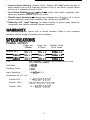
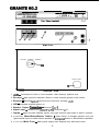
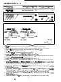
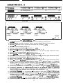
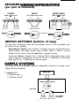
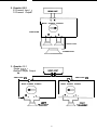
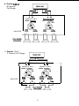
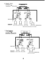
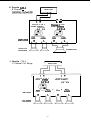
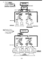
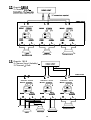
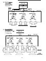
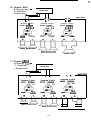
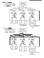
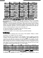
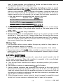
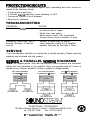
SOUNDSTREAM
Granite 60.2,
Granite 120.4 and
Granite 180.6
POWER
AMPLIFIERS
OWNER’S MANUAL &
INSTALLATION GUIDE
CONGRATULATlONS
You now own the Soundstream Granite Amplifier, the result of a unique design and
engineering philosophy.
To maximize the performance of your system, we recommend that you thoroughly
acquaint yourself with its capabilities and features. Please retain this manual and
your sales and installation receipts for future reference.
Soundstream amplifiers are the result of American craftsmanship and the highest
quality control standards, and if properly installed, should provide you with many
years of listening pleasure. Should your amplifier ever need service or replacement
due to theft, please record the following information, which will help protect your
investment.
Model
Serial Number
Dealer’s Name
Date of Purchase
Installation Shop
Installation Date
CAUTION!
Prolonged listening at high levels may result in hearing loss. Even though your new
Soundstream amplifier sounds better than anything you’ve ever heard, exercise
caution to prevent hearing damage.
DESlGN FEATURES
Handcrafted in the U.S.A. with mil-spec glass epoxy circuit boards, low-loss connections, gold plated input connectors, and metal film resistors.
Darlington High Current Discrete Output Topology - Soundstream’s “overbuild
ing” of the output section incorporates Darlington output devices sandwiched
between the circuit board and the heat sink in a design called ChassisinkTM to
ensure cool, efficient amplifier operation.
Mixed Mono Capable so you can simultaneously drive a stereo and mono load
(satellites and subwoofer).
2 Ohm Drive Ability - The Granite amplifiers are designed to drive loads all the
way down to 2 Ohms stereo and 4 Ohms bridged.
Built-in Staggered Asymmetrical Crossovers (Granite 120.4, Granite 180.6) Built-in electronic crossovers are designed to compensate for the acoustics of
the automobile environment. A high pass crossover (at 150 Hz @ 12 dB/octave)
and low pass crossover (at 75 Hz @ 12 dB/octave) allow you to drive a complete subwoofer and satellite system without the use of passive crossovers.
l
l
l
Internal Signal Routing (Granite 120.4, Granite 180.6) - Permits one pair of
signal cables to drive all 4 channels (Granite 120.4) or two pairs of signal cables
to drive all 6 channels (Granite 180.6).
Drive Delay Muted Tunum/off Circuit - a unique circuit which completely eliminates any amplifier-related turn-on/off noises.
Flexible Input Sensitivity - accepts input voltages from 100 mV to 2.5 V, which
permits maximum output from amplifier with virtually any source unit.
*“Balancing Act” Input Topology for added immunity to ground loops caused by
component and vehicle electrical system interaction.
Your Granite amplifier comes with a limited warranty. Refer to the enclosed
warranty card for length of warranty and conditions.
SPECIFlCATIONS
POWER OUTPUT
Power into
4 Ohms
Power into
2 Ohms
Bridged Power
into 4 Ohms
Granite 60.2
3Owx2
5Owx2
loowxl
Granite 120.4
3owx4
5owx4
lOOWx2
Granite 180.6
.3Owx6
50~x6
lOOwx3
THD
< O.l%, 20Hz-20kHz at rated power into 4 ohms
S/N Ratio
>90 dB
Damping Factor
>200
Input Sensitivity
100 mV - 2.5 V
Dimensions (W x D x H)
Granite 60.2
7” x &3/16” x 2-3/16”
Granite 120.4
95/8” x 83/16” x 2-3/16”
Granite 180.6
12” x 83/8” x 2-3/16”
2
GRANITE 60.2
Side View
MONO STEREO STEREO
o-
8
.
MAIN FUSE
9
-0
Underside View
1. +W - Connected to fuse or circuit breaker, then battery’s positive post.
2. Ground - Main ground connection. Bolt to a clean chassis ground in the vehicle.
3. Remote - Remote tumon input from the head unit. Accepts +12V.
4. LED - Indicates amplifier power on.
5. Speaker Output ConnectIons - Channels
(1
+2)
6. Input Level - Variable from 100mV to 2.5V (Channels 1 + 2).
7. Inputs - Right and Left Channel inputs; only right channel input used in “Mono” position.
8. [underside] Mono/Stereo/Stereo Switch - Select “Mono” for bridged operation (only use
right channel input) or either Stereo position for 2channel Stereo or Mixed Mono operation.
9. [underside] Main Fuse - Main power supply fuse. Replace only with same value.
3
GRANIlE120.4
.->A- --
5 ’
1
6
0’ -0‘ 7
-,--I
8
Side View
CflOnllOlS3UldA
Channets 1 and 2
MONO
r~~oi
twut
tnprt
twut
mm Right FKlm3u ficm3+4
MONO
tnpur
FmmRkJht
r STEREO 7
tnput
tnwt
Ffom1+2 Fmm3+4
1 5a
u
L-J Underside View
1. +I2V - Connected to fuse or circuit breaker, then battery’s positive post.
2. Ground - Main ground connection. Bolt to a clean chassis ground in the vehicle.
3. Remote - Remote turn-on input from the head unit. Accepts +12V.
4. LED - indicates amplifier power on.
5. Speaker Du@ut Connections - Channels (1 + 2 )
6. Input Level - Variable from 100mV to 2.W (Channels 1 + 2).
7. Inputs - Standard RCA style connectors (Channels I+ 2). Right channel only for mono.
8. Speaker Output Connections - (Channels 3 + 4)
9. Input Level -Variable from 1OOmV to 2.5V (Channels 3 + 4).
10. Inputs - Standard RCA style connectors (Channels 3 + 4). Right channel only for mono.
11. [underside]Channels 3 + 4 Mono/Stereo (input 3 + 4)/Stereo (input 3 + 4) Switch
MONO position for single channel operation (only right channel is active in Mono). Use
either STEREO input position with RCA inputs from Channels 3 + 4.
12. [underside] Channels 3 + 4 Cnwsover - Select either full range or high pass (150H2,
12dB/octave) operation.
13. [underside] Channels 1 + 2 Mono/Stereo (input 1 + 2) / Stereo (input 3 + 4) Switch
MONO position for single channel operation (only right channel is active in Mono). Use
“STEREO 1+2” for RCA inputs 1+2. Use “STEREO 3+4” for RCA input 3+4.
14. [underside] Channels 1 + 2 Crossover - Select either full range or low pass (75H2,
12dB/octave) operation.
15. [underside] Main Fuse - Main power supply fuse, replace only with same value.
4
0
GRANITE180.6
u
u
UndersIde View
u
1. +I2V - Connected to fuse or circuit breaker, then battery’s positive post.
2. Ground - Main ground connection. Bolt to a clean chassis ground in the vehicle.
3. Remote - Remote turn-on input from the head unit. Accepts +12V
4. LED - Indicates amplifier power on.
5. Speaker Output Connections - Channels (1 + 2 )
6. Input Level - Variable from 1OOmV to 2.5V (Channels 1 + 2).
7. Inputs - Standard RCA-type connectors (Channels 1 + 2). Use only right channel for mono.
8. Speaker Output Connections - (Channels 3 + 4)
9. input level - Variable from 100mV to 2.5V (Channels 3 + 4).
10. Inputs - Standard RCA-type connectors (Channels 3 +4). Use only right channel for mono.
11. Speaker Output Connections - (Channels 5 + 6)
12. Input Level -Variable from IOOmV to 2.5V (Channels 5 + 6).
13. Inputs - Standard RCAtype connectors (Channels 5 +6). Use only right channel for mono.
14. [underside] Channels 5 + 6 Mono/Stereo (input 5 + 6) / Stereo (input 3 + 4) Switch
MONO position for single channel operation. (Only right channel is active in Mono) Use
“STEREO 5+6” for RCA inputs 5+6. Use “STEREO 3+4” for input from RCAs 3+4.
15. [underside] Channels 5 + 6 Crossover - Full range or high pass (150Hz,12dB/octave).
16. [underside] Channels 3 + 4 Mono/Stereo (input 3 + 4) / Stereo (Input 3 + 4) Switch
MONO position for single channel operation. (Only right channel is active in Mono) Use
either STEREO input position with RCA inputs from Channels 3 + 4.
17. [undersidejchannels 3 + 4 Crossover - Full range or high pass (150Hz, 12dB/octave).
18. [underside] Channels 1 + 2 Mono/Stereo (input I+ 2) / Stereo (input 3 + 4) Switch
MONO position for single channel operation (only right channel is active in Mono). Use
“STEREO 1+2” for RCA inputs 1+2. Use ‘STEREO 3+4” for input from RCAs 3+4.
19. [unde&de]Chann& 1 + 2 Crossover - Full range or low pass (75Hz, 12dB/octave).
20. [underside] Main Fuse - Main power supply fuse, replace only with same value.
5
SPEAKER WBRlNG CONFlGlJRAVlONS
(per pair of channels)
STEREO
Use L & R inputs
STEREO
MONO
MIXED MONO
Use L & R inputs
Use Right input only
MONO @
S T E R E O MONO m STEREO
SWITCH SETTINGS (bottom of amp)
For each pair of’channels, there are two switches (one on 60.2) accessible from
the bottom of the amplifier.
Mono/Stereo Switch: Set to “Mono” to bridge one pair of channels into a
single channel. Only Right channel input is active. When in “Stereo,” a mono
channel can be driven using Left - & Right + speaker outputs.
Crossover Switch (Granite 120.4, Granite 180.6): Defeatable high or low
pass crossover. Frequencies are set at 150 Hz, 12 dB/octave on the high
pass and 75 Hz, 12 dB/octave on the low pass.
Following are several possible system configurations driven by a single or two
bridged Granite amplifiers.
HEAD UNIT
1. Granite 60.2
2 Channel Input /
2 Channel Output
J. R
MONO STEREO STEREO
0
AMPLIFIER
+‘I_
+.L _
FULL-RANGE
SPEAKERS
6
2. Granite 60.2
2 Channel Input /
3 Channel Output
]
1 MONO STEREO STEREO
AMPLIFIER
+B-
+L-
SATELLITES
SUBWOOFER
3. Granite 60.2
Single Input /
Bridged
Amps Output
_
I I
AMPLIFIER #l
I
-A
I-I
I. R
L
s
0
@
x
A*-
R
MONO STEREO STEREO
MONO STEREO STEREO
L
AMPLIFIER #2
*L_
LECT
FULL-RANGE
SPEAKER
SPEAKER
7
4. Granite 120.4
4 Channel
Full Range
Channels 3 and 4
MONO STEREO
ch8nnels 1 and 2
STEREO
MONO
AMPLIFIER
5. Granite 120.4
2 Channel Full Range
I
4.
R
I. R
Channels 3 and 4
MONO STEREO
33~
---1
Channels 1 and 2
MONO STEREO
G-z
“,S@
PASS
R?kE
@
R%k
l%!z
AMPLIFIER
+R-
+‘L_
+a_
I
8
+*L -
6. Granite 320.4
4 Channel Satellites/2 Subwoofers
HEAD UNIT
Channels 3 and 4
MONO STEREO
3J+i
Channels 1 and 2
MONO STEREO
15-Z
AMPLIFIER
SATELLITE
SPEAKERS
SUBWOOFERS
7. Granite 120.4
3 Channel Satellites/Subwoofer
L R
Channels 3 and 4
MONO FTERE?
3+4 3+4
Channels 1 and 2
MONO STEREO
13+4
AMPLIFIER
I
+=_
+‘_
SATELLITE
SPEAKERS
+=-
SUBWOOFER
9
8. Granite l20.4
2 Channel Satellites/Subwoofer
HEAD UNIT
“”
I. R
Chammlsl and2
M O N O STST
Channels 3 and 4
MONO STEREO
&i--z
1+2
3+4
AMPLlFlER
+=-
+L_
+R_
+L_
SATELLITE
SPEAKERS
SUBWOOFER
9. Granite 120.4
4 Channel Full Range
I
I
HEAD UNIT
Channels 3 and 4
MONO BTERECj
3+4 3+4
",G@
PASS
R?ii%E
Channels 1 and 2
MONO STEREO
l3+4
L
O
PASS
W
@
R%k
AMPLIFIER
+=-
+‘_
FULL-RANGE
SPEAKERS
10
+R_
+L_
10. Granite 120.4
2 Channel lrtput with
External Crossover Satellites/Subwoofer
I
1
I 1
High Pass
L
I
Low Pass
’
R
1
Channels3and4
MONO STEREO
R
Channels land
2
Sm
MONO
AMPLIFIER
SATELLITE
SPEAKERS
IA.. Granite 120.4
2 Channel Input 2 pair Satellites/
2 Subwoofer
HEAD UNIT
mr,
4. R
Channels3and4
MONO ST$T
3+4
Charm&land2
MONO STEREO
3+4
.a
R?i%E
PASS
G-z~
@
P%
R~iE
AMPLIFIER
+R-
+R-
+:‘ -
1
l2. Granite 180.6
2 Channel input Satellites/Subwoofer
[,r.,:,,]
Channels 5 and 6
+L_
+=-
I
I
+=_
+L_
I
I
+=_
+L_
I
I
~=vPc
SA;E,TE
RIGHT
SATELLITE
SUBWOOFER
fin
r\rl
R
L. R
13. Granite 180.6
4 Channel Input (fadable) 3 Channel + Sub
L
R
I.
AMPLIFIER
Channels S and 6
MONO STEREO
55-z
Channels 3 and 4
MONO STEREO
z-z4
..@
PASS
R?i%E
..“@
PASS
R%%E
Low@
PASS
R%tE
+=_
+=_
+=-
+‘_
+L_
Channels 1 and 2
MONO STEREO
;+2z-z
+L_
I
.
SUBWOOFER
RIGHT
12
14. Granite 180.6
Ti-iamp with
External 2-way
Crossover
HEAD UNIT
I I
sx-2
34ooHz
LowPass
34ooHz
b
Fl
c1m
AMPLIFIER
Channels 5 and 6
MONO STEREO
TWEETERS
MID-WOOFERS
SUBWOOFER
15. Grantte 180.6
2 Channel Input 6 Satellites/
3 Subwoofers
HEAD UNIT
mm
Channels 5 and 6
13
AMPLIFIER
16. Granite 280.6
4 Channel Input 4 Satellites/
Subwoofer
HEAD UNIT
I 1
AMPLIFIER
nl-8
mm
t R
L
Channels 5 and 6
M O N O ST5+6 3+4
Channels 3 and 4
MONO STEREO
3;44
Channels 1 and 2
M O N O S5
1+2 3+4
HIGH-FULL
RANGE
PAS!5
HIGH-FULL
PASS
RANGE
L
R
I?
LOW-FULL
RANGE
PASS
‘j
SUBWOOFER
17. Granite 180.6
4 Channel input 4 Satellites/
2 Subwoofers
Channels 5 and 6
“,Gi
MONO
BTERE?
PASS
+R-
R%%E
+L_
HEAD UNIT
yjAi&
Z-k
PASS
+‘_
+R_
~tK~
R%%E
PASS
+R_
+L_
FRONT SATELLITES
REAR SATELLITES
SUBWOOFERS
14
18. Granite l80.6
6 Channel Input using
External Crossover Front & Rear Satellites/
2 Subwoofers
Channels 5 end 6
Channels 3 and 4
Channels 1 and 2
19. Granite 180.6
6 Channel Input using
External Crossover/
Triamp Tweeters, Mid
Woofers, Subwoofers
HI& Pass
>3cwoNz
Channels 5 and 6
SUBWDOFERS
PASSIVE AND ELECTRONlC CROSSOyERS
Your Granite amplifier is capable of driving a complete subwoofer and satellite sys
tern in the Mixed Mono configuration. However, for the lowest distortion and the maximum output and sound quality, we recommend that you use electronic crossovers
and multiple channels of amplification, as provided in the Granite 120.4 and the
Granite 180.6.
If only two channels of your Granite amplifier are going to be used to drive a sub
woofer and satellite system, passive high and low pass crossovers will be necessary. Use the following charts to determine the values of the crossover components.
6 db/Octave Passive Crossover Chart
KfY L = high quality (DCR < 1 Ohm) inductor/coil
C = nonpolarized 50v (or greater) capacitor
6 dB/Octave Low Pass
6 dB/Octave High Pass
12db/Octave Passive Crossover Chart
KEY:
Ll = high quality (DCR < 1 Ohm) inductor/coil
Cl = non-polarized 5Ov (or greater) capacitor
12 dB/Octave Low Pass
12 dB/Octave High Pass
16
4 Ohms
2 Ohms
mEQ
Ll
8 Ohms
C l
Ll
C l
Ll
C l
80Hz
5.5mH
68Oj.lF
IlmH
33OpF
22mH
18O)lF
IOOHz
4.7mH
9.lmH
6.8mH
18mH
15OpF
3.3mH
56OpF
4OOcF
27OpF
130Hz
2OOpF
15mH
1OObF
200Hz
2.2mH
4.7mH
15OpF
9.lmH
75pF
260Hz
1.8mH
3OOpF
2OOpF
3.6mH
1OOpF
6.8mH
5OpF
400Hz
l.lmH
15OpF
2.2mH
33pF
0.75mH
1oopF
1.5mH
68pF
47~F
4.7mH
600Hz
3.0mH
26pF
800Hz
IOOOHz
0.5mH
0.47mH
68pF
l.OmH
33lF
2.0mH
15pF
0.9lmH
27pF
1.8mH
1200Hz.
0.33mH
5OpF
44pF
0.75mH
22pF
1.5mH
13~F
IlpF
1800Hz
0.27mH
3OpF
0.50mH
15pF
4000Hz
O.lOmH
15pF
0.22mH
6.8pF
l.OmH
0.47mH
6.8pF
3.3pF
AMPLIFIER LOCATiON AND MOUNTING
Soundstream Granite amplifiers employ highly efficient circuitry and a unique
ChassisinkTM design to maintain lower operating temperatures. When mounting the
amplifier, it should be securely attached to either a panel or to an amp board or
rack that is securely fastened to the vehicle, away from moisture, stray or moving
objects, and major electrical components (electrical motors, fuel pumps, etc.). To
provide adequate ventilation, mount the amplifier so that there are at least two
inches of freelycirculating air above and to the sides of it.
A. Using the amplifier as a template, mark the mounting surface.
B. Remove the amplifier and drill the holes.
C. Mount the amplifier to the surface using the provided hardware.
WIRING
You will need the following tools for the wiring of the amplifier: Phillips or slotted
screwdriver, wire strippers and wire crimpers.
When baring wires for connection to the amplifier, remove 3/8” to l/2” of the
insulation. For the speaker leads, use the supplied l/4” insulated female crimp
connectors and slide the connector onto the terminal on the amplifier. On the
power, ground and remote connections, loosen the screws on the terminal block,
slide the bared wire into the connector-and tighten the screw. Determine from the
chart below the minimum gauge power and ground wire required. Be sure to fuse
the amplifier positive power lead within 18” of the battery.
Amplifier
up to 70’
up to 20’
up to 75’
up to 5’
Granite 60.2
12 ga or larger
12 ga or larger
10 ga or larger 10 ga or larger
Granite 120.4
12 ga or larger
12 ga or larger
10 ga or larger 10 ga or larger
Granite 160.6
10 ga or larger
8 ga or larger
8 ga or larger
8 ga or larger
A. Carefully run the audio and remote turn-on cabIss to the amplifier.
B. Connect the speakers as shown in “Speaker Wiring Configurations.” Use at
17
least 16 gauge speaker wire, preferably a flexible multi-strand cable, such as
Soundstream Speaker 120 or Speaker 160.
C. Carefully run the positive power cable from the battery to a fuse or circuit
breaker and then to the amplilier. Connect the lead to the battery via either a
fuse or a circuit breaker within 18 inches of the battery. Leave the fuse out or
the circuit breaker off until the installation is otherwise finished. If the circuit
breaker cannot be shut off manually, do not make the final power connection to
it. See chart below for recommended fuse ratings to be used.
Amplifier
Amplifier Fuse Battery Fuse
Granite 60.2
15 A automotive
20A
Granite 120.4
25 A automotive
30 A
Granite 160.6
30 A automotive
30Ato50A
D. Run a ground cable for the amplifier and securely connect it to a solid chassis
ground on the vehicle. The ground cable should be the same gauge as the
power cable.
E. Double check each and every connection.
F. Reconnect the fuse or circuit breaker. Power up the system and the red LED
should be lit. There may be a 2-3 second delay from the time that the source
unit is turned on to the time that the LED on the amp turns on. This is normal.
Once the amplifier power LED is on and the source unit is playing, you should
have sound coming from the speakers.
Wiring Tips
l
l
l
Use grommets when running cables through any metal or sharp plastic to
prevent accidental shorting or shearing.
Be certain that the cables don’t interfere with normal operation of the vehicle.
Choose the location of the audii cables carefully to prevent interference with the
vehicle’s high current circuits and vehicle management systems (engine computers, relays, etc.).
LEVEL SEHlNG
The input levels are adjusted by means of a stereo level control located to the left
of the input connectors. When the amplifier is operated in the mono/bridged
mode, only the right channel input is active.
A. Turn the input level controls on the amp to minimum position (fully counterclockwise).
B. Set source unit volume to approximately 3/4 of full volume.
C. Adjust outboard crossover and processor level controls so the output level of
the processor/crossover equals the input level. To do this, you can plug the
head unit outputs directly into the amplifier and listen to one amp at a time (at
low levels) to establish a reference, then add the crossover or processor and
set its gains to match the reference.
D. While playing dynamic source material, slowly increase the amplifier’s input
level(s) until a near maximum undistorted level is heard in the system.
1 8
(continues on back cover)
PROTECTBON ClRClJmS
Your Granite amplifier is protected against both overheating and short circuits by
means of the following circuits:
l A main power supply fuse
l A fail-safe them-ral protection circuit activating at 85°C.
. Overcurrent Channel Circuit Breakers
l Short-circuit shutdown
TROUBLESHOOTING
PROBLEM
No Sound and LEDs are not lit
CAUSE
no power or ground at amp
no remote turn-on signal
blown fuse near battery
blown power supply fuse (accessible
through access cover on-bottom of amp)
l
l
l
l
Repeatedly blown amp fuse or
frequent activation of thermal
shut-off
l
l
l
speaker or leads may be shorted
verify adequate cooling of the amplifier
speaker load may be less than 2 Ohms
SERVICE
Your Soundstream amplifier is protected by a limited warranty. Please read the
warranty card enclosed with this product.
SERIES & PARALLEL WiRING DIAGRAMS
See the diagram below. Note that the manner in which speakers are connected
affects the load presented to the amplifier. Keep your speaker load at 2 ohms or
greater for any Granite amplifier (4 ohms or greater in Bridged Mode).
Two 4 Ohm Speakers
in PARALLEL = 2 Ohms
Two 4 Ohm Speakers
in SERIES = 8 Ohms
Two 8 Ohm Speakers
in PARALLEL = 4 Ohms
SOUNDSTREWl*
T
E
C
H
N
O
L
O
G
I
E
S
SOUNDSTREAM TECHNOLOGIES
120 Blue Ravine Road Folsom California 95630 USA
fax 916.351.0414
tel 916.351.1288
l
0 1993 - Tnhnologles
l
Fnnted m UsA
v5 , 520.93