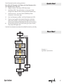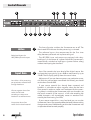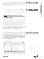
1
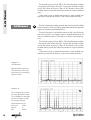
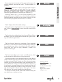
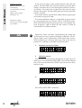
Manual
Spectralizer
Model 9631
Digital Harmonics Processor
SOUND PERFORMANCE LAB
SPECTRALIZER
MODEL 9631
Manual
by Hermann Gier and Paul White
Version 2.2 – 1/1999
The information in this document has been
carefully verified and is assumed to be correct.
However Sound Performance Laboratory (SPL)
reserves the right to modify the product
described in this manual at any time. Changes
without notice. This document is the property of
SPL and may not be copied or reproduced in
any manner, in part or full without the authorization of SPL.
Limitations of Liability:
In no event will SPL be liable for any damages,
including loss of data, lost profits, cost of cover
or other special, incidental, consequential or
indirect damages arising from the use of the
unit, however caused and on any theory of liability. This limitation will apply even if SPL or an
authorized dealer has been advised of the
possibility of such damage.
SPL electronics GmbH
P.O. Box 12 27
D- 41368 Niederkruechten, Germany
Phone: +49 - 21 63 / 9 83 40
Fax: +49 - 21 63 / 98 34 20
eMail: [email protected]
www.spl-electronics.com
© 1999 SPL electronics GmbH. All Rights Reserved.
Foreword
Thanks
Introduction
Operation Safety
Connections, installing Updates
Quick Start
Flow Chart
Control Elements
ACTIVE
INPUT GAIN
FREQUENCY
MIX
2ND HARMONIC
3RD HARMONIC
DENSITY
LC-DISPLAY
SOLO
KICK
PRESETS
INFO (Hardware dialogue)
OUTPUT PPM
Specifications
Warranty
3
3
4
5
6
7
7
Contents
8
8
9
9
9
10
11
11
11
11
11
12
15
16
17
Dear customer,
Thank you for the confidence you have shown towards SPL
electronics GmbH by purchasing the SPL SPECTRALIZER. You have
decided to use a tool of high performance which sets you in the
position to have faster success and a better sound quality in
your music productions and pre-masterings.
Foreword
As a typical SPL unit the SPECTRALIZER combines exemplary
specifications and high manufacturing standard with excellent
sound quality to provide you a precious component for studio
and mastering purposes. Please read this manual carefully to
ensure you have all the information you need to use the
SPECTRALIZER.
We wish you every success with the SPECTRALIZER.
Your SOUND PERFORMANCE LAB-Team
I would like to start with my thanks to all our staff, who
created what is to be described here. Special thanks go to Jörg
Houpert, Klaus-Peter Webersinke and Andreas Skäbe from
Spectral Design, as well as Harald Obenland from Octum electronics. The importance of their exceptional qualification and
talents cannot be overestimated.
Thanks
Our products are often tested and compared in many publications and by our customers themselfs and constantly valued
with best results. I would like to pass on this broad appreciation
to those, who deserve it – my excellent colleagues.
Hermann Gier
Spectralizer
3
Introduction
Re-synthesizing second and
third harmonics separately
Improving clarity, intelligibility and depth without
introducing harshness
Warm and smooth sounding
harmonic re-synthesis
SPL digital audio processors are designed in cooperation with
Spectral Design of Bremen, Germany, who are responsible for
the DSP programming.
Concept: The SPECTRALIZER is the first digital harmonics processor
employing a new process which allows you to re-synthesize
second and third harmonics separately, and with full control
over their amplitude.
The SPECTRALIZER benefits from SPL's expertise in psycho-acoustic principles and is the ideal tool to improve the clarity, transparency and intelligibility of any signal in the digital domain.
A single instrument or vocal gains better penetration within a
mix, while complete mixes benefit from improved subjective
loudness without a measurable change in levels.
While developing the DSP-program, a strong emphasis was
placed on achieving warm and smooth sounding harmonic resynthesis. The digital domain tends to be susceptible to “sharpness” at the HF end of the spectrum, which made the design of
the SPECTRALIZER all the more demanding. The result is a tool able
to increase brightness and detail without adding harshness or
sounding fatiguing.
In comparison to ostensibly similar analogue systems, the
SPECTRALIZER does not produce any phase deterioration, nor
introduce unmusical intermodulation products.
Easy and intuitive
operation
Operation: The SPECTRALIZER is fitted with six encoder controls,
and the actual parameters values are shown in the LCD
window. INPUT GAIN sets the overall input level with gain adjustment available from -20 dB to +6 dB, while the starting
frequency for the re-synthesis of the harmonics is set using the
FREQUENCY control. This functions as a high-pass filter adjustable
over the range 1kHz to 7 kHz in 500 Hz steps; signals with a
frequency lower than that selected using the FREQUENCY control
remain unaffected. The DENSITY control offers a choice of six
settings to determine the amplitude envelope of the added
harmonics and works rather like a digital compressor to
increase the density of the re-synthesized harmonics – which
makes them more prominent. The 2ND and 3RD HARMONIC
controls set the relative levels of the re-synthesized harmonics
while the MIX control defines the balance between the new
harmonics and the original signal.
The SPECTRALIZER has three switch functions: SOLO mutes the
original input signal so that the added harmonics can be heard
in isolation while KICK adds a greater proportion of harmonics
to transients (attack parts of the signal).
The ACTIVE button switches the SPECTRALIZER in and out of
operation; when connected via AES/EBU, a relay-operated
hard bypass switches the digital input directly to the output.
Signal flow remains uninterrupted, even if the mains power is
switched off.
The software bypass function compensates for the inevitable
(but very short!), digital domain processing delay so as to avoid
4
Spectralizer
the small timing glitches that would otherwise occur when
switching the process in and out. Up to 99 presets can be stored
and changed using a MIDI program change command.
Display: The SPECTRALIZER is equipped with two PPM-meters
that feature high resolution in the important region immediately before 0dB. Clip-LEDs indicate digital clipping, while the first
LED of each PPM-meter functions as a signal present indicator
to confirm that a digital signal is present at the input.
The philosophy behind the digital audio processors is that
they are designed to be operated like analogue units; there is
only one INFO menu but no multi-function controls. The LCD
readout simply shows the current encoder positions and the
preset number. The encoders are built without clicks or detents,
so they feel like analogue pots. Our DSP platform uses two
Motorola 56002 DSPs running at 66 MHz. This enormous
computational power guarantees real-time operation where
sophisticated DSP algorithms will not be restricted by resource
limitations. The general concept is that each digital processor
should fulfill only one task, in the most effective way possible,
and with a minimum of controls and switches. As much as
possible should be automated to promote user-friendly operation – the external controls access only the sonically relevant
parameters. Additionally all controls with a wide value range
(e.g. 0 to 100) are programmed with an 'alpha-dial' logic.
Turning the encoder rapidly causes the values to jump in steps
of 10, whereas turning the encoder slowly causes the values to
proceed in single increment steps.
The housing of the SPECTRALIZER has the standard 19"- EIA
format and occupies 1U (44 mm) in your rack. When installing
the unit in a 19"-rack, the rear side of the unit needs some
support, especially in a touring case.
Input and Output
PPM metering
“Analogue“ control feeling
The DSP Platform:
Enormous computational
power guaranteeing realtime operation
User-friendly programmed
software
Operation Safety
The SPECTRALIZER should not be installed near units which
produce strong magnetic fields or extreme heat. Do not install
theSPECTRALIZER directly above or below power amplifiers.
Check that the voltage details quoted on the back panel are
the same as your local mains electricity supply. Use a minus (-)
screwdriver to set the voltage selector to the voltage for the
area in which the unit will be used.
Never cover up the ventilation slots on the top of the unit. If,
during operation, the sound is interrupted or indicators no
longer illuminate, or if abnormal odor or smoke is detected, or
if liquids are spilled on the unit, immediately disconnect the
power cord plug and contact your dealer.
Only clean your SPECTRALIZER with a soft, lint-free cloth.
Spectralizer
5
Connections
Before connecting the SPECTRALIZER switch the power off at all
connected units.
The rear panel provides AES/EBU- and S/P-DIF-inputs and
outputs. Any additional channel, status and user-bits are
passed through unaltered, and the outputs can be used at the
same time if required.
The SPECTRALIZER operates with 24 bit word width. It accepts
16 bit and 20 bit inputs and will create output signals according to the input resolution.
For synchronisation purposes WORDCLOCK IN and WORDCLOCK
THROUGH BNC connectors are fitted with a switchable 75 Ohm
termination.
MIDI IN and MIDI THROUGH connectors allow presets to be
selected via MIDI program change commands.
For easy upgrade of future software releases, the rear panel
offers RS-232 interface for PC and RS-422 interface for MAC.
Installing Updates:
Note: All presets will be lost after installing a new software version!
1.
Connect your computer with the SPECTRALIZER via a serial
port with a standard Z-modem cable.
RS-232 for PC and RS-422 for MAC.
2.
Open a terminal program like “Hyperterminal” on PC
and make the following adjustments:
Baud rate: 9600; Stop bit: 1; Parity: none; Data bit: 8;
Handshake: no; Transfer mode: ZMODEM
Rear Panel Spectralizer
6
3.
Switch on the SPECTRALIZER and depress both
PRESET UP and PRESET DOWN until the LC-display says
“wait for Zmodem download“.
4.
Load the update file into your terminal program
and send it to the SPECTRALIZER. The LC-display
shows the progress of the download in kB.
5.
After successfully installing the new software version the
LC-display says “download valid”.
6.
Switch the SPECTRALIZER off and on. The new
software version number is displayed in the first INFO
page (simultaneously depress STORE and APPLY; also
refer to CONTROL ELEMENTS No. 9, INFO).
7.
If an error occurred during download the LC-display says
“download failed”. The SPECTRALIZER now waits
for a new download. Please check all adjustments on
your terminal program and try again. If you are still
unsuccessful contact your local dealer.
Spectralizer
Set all controls to the starting positions:
INPUT GAIN 0; FREQUENCY 1k; DENSITY 0; 2ND HARMONIC 0%;
3RD HARMONIC 0%; MIX 0%.
1.
Depress ACTIVE. The status-LED illuminates.
2.
Set MIX to 50%. You will notice an increase in high
frequencies above 1 kHz (starting position FREQUENCY).
3.
Set DENSITY to 1, to increase the audibility of the
harmonics in the next step.
4.
Set 2ND HARMONIC to 50% and 3RD HARMONIC to 30%.
5.
If you are using full scale material for this initial test
drive the CLIP LEDs may illuminate. Reduce the INPUT
GAIN to give additional headroom for the new harmonics.
6.
To compare original and processed signal press ACTIVE.
The status LED goes out.
Quick-Start
Use the SOLO button to monitor the added harmonics precisely.
Flow Chart
Input
Encoder
Effect
Original
FrequencyEncoder
HighpassFilter
Diagram 1:
Signalflow Spectralizer
Generator
2nd Harmonic
Encoder
Kick-
Density-
Encoder
Encoder
Generator
3rd Harmonic
Encoder
SoloTaste
MixEncoder
Spectralizer
7
Control Elements
8
9 10
2
3
Active
7
1
INPUT GAIN = 0 for processing
pre-production material with
enough headroom
Choose negative INPUT GAIN
values for full scale
recordings to create new
headroom to add harmonics
Use positive INPUT GAIN
values for low level material
8
6
4
1 13
12
The ACTIVE function switches the SPECTRALIZER on or off. The
illuminated LED indicates that the processing is activated.
The software bypass also compensates for the 5 ms time
delay between processed and unprocessed signal.
Relay hard-bypass for
AES/EBU input and output
Input Gain
5
11
The AES/EBU input and output are equipped with relayhard-bypass. In the event of a power failure the SPECTRALIZER is
automatically switched to hard-bypass (power failure safety)
without interrupting the data flow.
2
INPUT GAIN controls the input level of the digital source. You
can boost the input gain by up to +6 dB or attenuate it by up to
-20 dB. The LC-display (see 8) shows the actual value.
Adjustment: If you are about to process pre-production material which has not yet been normalized nor limited, you should
set the INPUT GAIN to 0 dB.
If your source material has already been mastered and
limited it is advisable to adjust negative values for the INPUT
GAIN control in order to create new headroom for the processing. Keep in mind that the SPECTRALIZER adds new harmonics to
the source material. If the source is a full scale recording the
added harmonics will immediately create an overload indicated by the illuminating CLIP LEDs.
If your source material has a very low level you can use the
SPECTRALIZER´S INPUT GAIN control to boost the level without making
changes to the sound. Additionally you drive the SPECTRALIZER into
an operational level to work properly.
Spectralizer
3
Frequency
MIX controls the mix level between the processed and the
unprocessed signal. The control range is 0 % to 100 %. The MIX
encoder is equipped with an „alpha-dial“ logic. Turning the
encoder rapidly causes the values to jump in steps of 10,
whereas turning the encoder slowly causes the values to
proceed in single increment steps.
4
Mix
5
2nd Harmonic
Control Elements
FREQUENCY sets the starting frequency of the highpass filter.
Above this frequency second and third harmonics are being
generated. The highpass filter can be varied between 1 kHz
and 7 kHz in steps of 500 Hz.
Example: All controls are set to the starting position:
INPUT GAIN 0; FREQUENCY 1k; DENSITY 0; 2ND HARMONIC 0%;
3RD HARMONIC 0%; MIX 0%.
Turn the MIX to 50%. You will hear an increase in high
frequencies above 1 kHz due to the starting position of the
FREQUENCY control. Until now you have not yet added any
harmonics. The increase in high frequencies is a boost of all
frequencies above 1 kHz. You can change the starting frequency
by turning the FREQUENCY encoder clockwise to higher frequencies. For some applications this may already do the job.
To add harmonics set 2ND HARMONIC to 50% and 3RD
HARMONIC to 30%. If the audible effect is very subtle increase
the DENSITY setting to 1 or 2 (details see DENSITY, 7).
The 2ND HARMONIC encoder controls the intensity of the
added second harmonics which are being generated above the
adjusted highpass frequency (see FREQUENCY, 3).
The second harmonics are even harmonics which bring a soft
and silky top-end to the sound. In comparison to odd harmonics, even harmonics do not contain as much brightness and
they also do sound softer.
Diagram 2:
2ND HARMONIC
The illustration shows the
FFT spectrums of the even
harmonics for a measuring
signal of 3 kHz.
Spectralizer
9
Control Elements
The control range is 0 % to 100 %. The 2ND HARMONIC encoder
is equipped with alpha-dial logic. Turning the encoder rapidly
causes the values to jump in steps of 10, whereas turning the
encoder slowly causes the values to proceed in single increment
steps.
If the need arises to make the harmonics more audible use
the DENSITY control (see DENSITY, 7) to increase their loudness.
3rd Harmonic
6
The 3RD HARMONIC encoder controls the intensity of the added
third harmonics which are being generated above the adjusted
highpass frequency (see FREQUENCY, 3).
The third harmonics are odd harmonics which carry brilliance
but also sharpness and aggressiveness. A good combination of
even and odd harmonics is the key to a natural sounding topend.
The control range is 0 % to 100 %. The 3RD HARMONIC encoder
is equipped with alpha-dial logic. Turning the encoder rapidly
causes the values to jump in steps of 10, whereas turning the
encoder slowly causes the values to proceed in single increment
steps.
If the need arises to make the harmonics more audible use
the DENSITY control (see DENSITY, 7) to increase their loudness.
Diagram 3:
3RD HARMONIC
The illustration shows the
FFT spectrums of the odd
harmonics for a measuring
signal of 3 kHz.
Diagram 4:
If two frequencies are fed
into the Spectralizer (here
3 and 4 kHz) also the differential tone (here 7 kHz)
are being produced
All measurements at:
1kHz
FREQUENCY
0
DENSITY
100%
MIX
10
Spectralizer
DENSITY increases the loudness of the generated harmonics by
applying different “compression ratios”. The control offers six
positions.
Density
8
LC-display
The SOLO function switches the original input off. You will hear
the effect signal only to be able to monitor the highpass-filtering and harmonics generation.
9
Solo
The KICK function boosts the amplitude of the generated
harmonics in the event of creation (attack-period). After that
the amplitude drops back to its original value. KICK should be
used when you want to apply additional “sparkle” and
presence to the signal.
10
Kick
The SPECTRALIZER allows you to store up to 99 presets, which
can be changed by MIDI program change command.
11
Preset
Control Elements
7
Adjustment: If DENSITY is set to 0, the generated harmonics
have low intensity even at high values for 2ND and 3RD
HARMONIC. The increase in high frequencies is mostly created by
the highpass filtering, which applies a shelving equalizing
above the adjusted FREQUENCY encoder (see FREQUENCY, 3).
Increasing DENSITY to 1 or 2 will increase audibility of the
generated harmonics. High DENSITY values (4 to 6) may lead to
audible distortion depending on the source material. Use the
SOLO function (see 9) to hear the harmonics in isolation.
The LC-display shows all encoder settings.
More information is displayed when activating the INFO pages
(see 9). Press STORE and APPLY for one second to enter the INFO
pages.
If you want to store a new adjustment, depress STORE for one
second. The LED starts to flash indicating that the STORE mode
has been activated. The LC-display now shows the actual preset
number. Use UP and DOWN to select a new preset location. The
status-LED flashes shortly to indicate that the input (depressing
UP or DOWN) is accepted. Keeping UP or DOWN depressed will
let you jump through the preset list in steps of 5 presets. Once a
new preset location is found depress STORE again. The STORE
LED goes out. The preset is stored at the new location.
In case you want to quit the STORE mode without storing the
new adjustments simply press APPLY.
Spectralizer
Storing a preset:
Depress STORE for1 sec.,
LED flashes;
use UP/DOWN to select
preset no.;
depress STORE again,
LED goes out
11
Control Elements
Applying a preset:
Depress APPLY for1 sec.,
LED flashes;
use UP/DOWN to select
preset no.;
depress APPLY again,
LED goes out
If you want to apply various presets depress APPLY for one
second. The APPLY LED starts to flash indicating that the APPLY
mode is activated. You can step through the preset list with UP
and DOWN. Once you have a preset that you want to apply
depress APPLY again. The APPLY LED goes out indicating that the
preset is applied.
Operation safety:
Presets can not be changed
by accident
To increase operation safety it is impossible to apply presets
by simply depressing UP or DOWN. The UP and DOWN statusLEDs will not flash indicating that the input is not accepted. You
have to depress STORE or APPLY for one second in order to
activate the UP and DOWN buttons.
Info
In case you want to quit the APPLY mode without applying the
new preset simply press STORE.
12
Depressing STORE and APPLY simultanouesly for about one
second gets you into a hardware dialogue, called INFO. The LCdisplay shows status informations of the digital data stream.
With UP/DOWN you will jump from one page to the next or
previous. If a selection is provided use APPLY to select.
1.
Software version and date
2. Selecting inputs:
The SPECTRALIZER automatically searches for an input signal. If
both inputs are connected the AES/EBU input will be selected
first. If you want to select the S/P-DIF input you have to call up
the INFO pages.
AES/EBU input detected
or:
no AES/EBU input detected
Press APPLY (if AES/EBU is detected):
AES/EBU input with wordclock detected
12
Spectralizer
AES/EBU input without wordclock is detected
Press APPLY :
S/P-DIF input detected
Control Elements
or:
or:
no S/P-DIF input detected
Press APPLY (if S/P-DIF is detected):
S/P-DIF with wordclock detected
or:
S/P-DIF input without wordclock is detected
3.
Displaying the detected sample frequency:
The SAMPLE FREQUENCY will be detected automatically.
The display either shows 44,1 kHz, 48 kHz or 32 kHz.
4.
Displaying the Audio-Error flag:
NO = no error detected; YES = error detected
5.
Displaying the CRC-Error flag:
NO = no error detected; YES = error detected
Spectralizer
13
Control Elements
6.
Displaying the Channel Difference Error flag:
NO = no error detected; YES = error detected
7.
Setting or erasing the Copy-Prohibit flag:
NO = flag erased or not set; YES = flag set
8.
Displaying the Original flag:
NO = no Original flag; YES = Original
9.
Displaying the Emphasis flag:
NO = no emphasis; YES = with emphasis
10. Selecting a serial port:
RS-232 interface for update-download from PCs
or (press APPLY):
RS-422 interface for update-download from MACs.
11. Selecting a MIDI channel:
Depress APPLY to step from MIDI CHANNEL 01 up to
MIDI CHANNEL 16.
14
Spectralizer
In order to increase operation safety only send the necessary
MIDI data to the SPECTRALIZER. Unnecessary information might
lead to system failure.
You can use MIDI to create a MIDI fade out, if you are
working with a digital console that does not provide master
inserts. The UP and DOWN LEDS illuminate indicating that a
volume change command is received.
You can also switch between presets with the MIDI program
change command. This can especially be useful, when you are
mastering a song, for example, that requires different settings
for chorus, refrain, or bridge. The APPLY LED illuminates indicating that a program change command is received.
MIDI IMPLEMENTATIONS
Function
Received Data
Note
Basic Channel:
Change
1-16
stored
Control Change:
7
1-127
Volume
0-99
real value
Program Change:
You leave the INFO-pages by depressing STORE.
The OUTPUT LED chains are PPM (peak level) meters with
signal and clip indicators. The metering offers 1 dB resoltion for
the last 3 dB before 0 dB.
13
Output PPM
The first LED in the OUTPUT PPM meter is a signal (SIG.) LED
to indicate that a valid digital source is connected and detected.
This LED helps you to verify the signal flow within a digital
processing chain. If one SIG. LED is not illuminating you have a
first indication of a faulty digital signal flow.
The last LED of the OUTPUT PPM meter is a CLIP LED. The LED
illuminates if the digital signal is too hot causing digital distortion.
Spectralizer
15
Specifications
Input/Output
Sample rate frequency, autom.
32-48kHz
AES/EBU, twisted pair (1)
AES/EBU in- & output impedance
AES 3
110 Ohms
S/P-DIF, co-axial (2)
S/P-DIF input impedance
SPDIF-2
75 Ohms
Wordclock In/Through, co-axial
Wordclock in-/output impedance
BNC
75 Ohms
MIDI In/Through
yes
RS 232
RS 422 (max +/- 14 V)
yes
yes
Clip display
yes
Input transformer (AES/EBU)
Output transformer (AES/EBU)
Relay Hard Bypass (AES/EBU)
yes
yes
yes
Measurements
AES/EBU: Jitter
S/P-DIF: Jitter
Wordclock In: Jitter
1ns
3ns
1,5ns
Power supply
Torroidal transformer
Fuse
GND-Lift switch
Voltage selector
60 VA
1A/slow blow
yes
115V/230V
Dimensions
19"/1U
482 x 44 x 350mm
Weight
4,9 kg
(1) AES/EBU is defined for levels from 2 V to 7 V
Measurements AES/EBU: 4,4 V with load
(2) S/P-DIF is defined for levels from 200 mV to 700 mV
Measurements S/P-DIF: 500 mV with load
Subject to change without notice.
16
Spectralizer
SPL electronics GmbH (hereafter called SPL) products are
warranted only in the country where purchased, through
the authorized SPL distributor in that country, against
defects in material or workmanship. The specific period of
this limited warranty shall be that which is described to the
original retail purchaser by the authorized SPL dealer or
distributor at the time of purchase.
Warranty
SPL does not, however, warrant its products against any
and all defects:
1) arising out of materials or workmanship not provided
or furnished by SPL, or 2) resulting from abnormal use of
the product or use in violation of instructions, or 3) in
products repaired or serviced by other than authorized SPL
repair facilities, or 4) in products with removed or defaced
serial numbers, or 5) in components or parts or products
expressly warranted by another manufacturer.
SPL agrees, through the applicable authorized distributor,
to repair or replace defects covered by this limited warranty
with parts or products of original or improved design, at its
option in each respect, if the defective product is shipped
prior to the end of the warranty period to the designated
authorized SPL warranty repair facility in the country where
purchased, or to the SPL factory in Germany, in the original
packaging or a replacement supplied by SPL, with all transportation costs and full insurance paid each way by the
purchaser or owner.
All remedies and the measure of damages are limited to
the above services. It is possible that economic loss or injury
to person or property may result from the failure of the
product; however, even if SPL has been advised of this
possibility, this limited warranty does not cover any such
consequential or incidental damages. Some states or countries do not allow the limitations or exclusion of incidental
or consequential damages, so the above limitation may not
apply to you.
Any and all warranties, express or implied, arising by law,
course of dealing, course of performance, usage of trade, or
otherwise, including but not limited to implied warranties
of merchantability and fitness for particular, are limited to a
period of 1 (one) year from either the date of manufacture.
Some states or countries do not allow limitations on how
long an implied warranty lasts, so the above limitations
may not apply to you.
This limited warranty gives you specific legal rights, and
you may also have other rights which vary from state to
state, country to country.
SPL electronics GmbH
41372 Niederkrüchten, Germany
Spectralizer
17