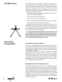
1
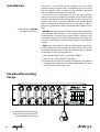
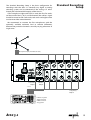
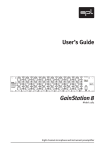
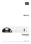
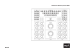
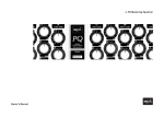
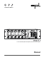
Area 5.1
5.1 Surround Microphone Preamplifier & Stereo Downmix System
Manual
Area 5.1 Model 2047
-Manual
Version 1.0 - 5/2000
The information in this document has been carefully verified and
is assumed to be correct. However Sound Performance Lab (SPL)
reserves the right to modify the product described at any time.
Changes without notice. This document is the property of SPL
and may not be copied or reproduced in any manner, in part or
full without the authorization of SPL.
Limitations of Liability:
In no event will SPL be liable for any damages, including loss of
data, lost profits, cost of cover or other special, incidental, consequential or indirect damages arising from the use of the unit,
however caused and on any theory of liability. This limitation will
apply even if SPL or an authorized dealer has been advised of the
possibility of such damage.
Sound Performance Lab
P.O. Box 12 27
D- 41368 Niederkrüchten, Germany
Phone + 49 - 21 63 / 98 34-0
Fax + 49 - 21 63 / 98 34-20
eMail: info@ soundperformancelab.com
www.soundperformancelab.com
2
Area 5.1
Introduction ............................................................................................... 3
Contents
Feature List ................................................................................................. 7
Installation ................................................................................................. 4
Standard Recording Setup .................................................................... 4
SPL Mic Array .............................................................................................. 6
Operation
Preamplifier .................................................................................... 6
Sub/LFE channel ........................................................................... 7
Stereo downmix stages .............................................................. 8
Stereo output ................................................................................. 8
Monitoring ...................................................................................... 8
Output PPM meter ........................................................................ 8
Power Supply ............................................................................................. 9
Specifications ............................................................................................ 9
Warranty ......................................................................................................10
Notes ...........................................................................................................11
Dear customer,
Introduction
congratulations on choosing the Area 5.1 for producing your 5.1
recordings. We are sure you have as much pleasure using it as we
had making it.
The complete Area 5.1 system contains the Area 5.1 unit and
optionally the SPL mic array and a multicore cable. Though the
Area 5.1 unit could be used with any microphone setup, the
combination with the SPL mic array is recommended since it is
the first proven standard setup to capture three-dimensional sound
images in all recording situations.
This authentic approach in terms of human perception also
minimizes the efforts to set up an 5.1 microphone installation.
Another essential feature is the stereo downmix stage that allows
to record both stereo and 5.1 simultaneously.
Since the Area 5.1 constitutes an electroacoustical system in
highest degrees of complexity, there are a few things to mention.
This manual contains basic informations regarding setup, connections, first placing in operation and control elements.
Area 5.1
3
Installation
Connect all devices BEFORE
switching on the Area 5.1
The Area 5.1 unit should not be installed near units which
produce strong magnetic fields or extreme heat. Do not install
the unit directly above or below power amplifiers. Generally
choose a place with sufficient air circulation.
The mic array has to be placed the way that the LCR heads
(those closer to the microphone center/90° angle) are facing the
sound source. Be aware that placing the mic array close to the
ground may result in ground reflections and comb filtering
effects. The best horizontal position for the mic array is right on
the crossing between the direct sound field and the diffuse sound
field.
BEFORE switching on power, make sure that the microphones
are connected with the Area 5.1 unit. (optional multicore lead
recommended). Check that the voltage details quoted on the
back panel are the same as your local mains electricity supply. Use
a minus (-) screwdriver to set the voltage selector to the required
voltage.
NOW switch on the Area 5.1. Chassis ground and AC ground can
be disconnected by the “Ground Lift” switch (GND LIFT) on the
back panel, if hum problems occur. An AC power cord is included
to feed the IEC-spec, 3-prong connector.
After switching on the Area 5.1, proceed as follows:
1) Press the Ch. 1-4 Lock button of channel 5.
2) Turn the Mic Gain control of channel 5 clockwise until sufficient
recording level is indicated at the PPM output meters (all other
mic gain controls follow precisely)
Standard Recording
Setup
See chapter Operation/Monitoring,
page 8, for further information on
stereo headphone monitoring
4
Area 5.1
The Standard Recording Setup is the basic configuration for
recordings with the Area 5.1. Generally any digital or analog
recording system can be connected to the analog 1/4" unbalanced jack or balanced XLR outputs of the Area 5.1.
Standard Recording
Setup
If, for example, an eight-track DTRS is used, the first five tracks
can be used for the L, C, R, SL and SR channels, the sub bass signal
should be routed to the sixth track, track seven and eight can be
used to record the stereo downmix.
We recommend to connect the five microphones with the
optionally available multicore lead to exclude differences
between the particular channels caused by varying tolerances of
single wires.
Microphone Input (via multicore lead)
Stereo Mix
Output
Sub Bass
Output
12345
L (1), C (2), R (3),
SL (4), SR (5)
Output
DTRS or any other
digital or analog
multitrack recording system
Area 5.1
5
SPL Mic Array
The SPL Mic Array was designed to arrange any suitable microphones in the setup based on the ASM 5 design of SPL’s Atmos 5.1
system. The outstanding quality of its 5.1 surround reproduction
has been proven in many occasions. With large double
membrane microphones in use, excellent tonal results are
combined with minimum efforts. Basic advantages of the combination with the SPL Mic Array are:
• First proven standard setup to capture three-dimensional sound
images in all recording situations
• Only one mic stand to mount the array
• Easy to move / fast and easy positioning
• Suited for all microphone types (matched mics recommended)
• First discrete 5.1 system for motion recordings
To get the most out of the Area 5.1 system it is essential to use
appropriate microphones. Most important for best results is to
use matched microphones at least for the L/R and SR/SL channel
pairs, however we recommend to employ five matched microphones with large double membranes.
To start, choose cardioid microphone characteristics for all
five microphones. The microphones should point in the directions shown in the graphic to the left. Many variations of this
setup, depending on the microphones and recording situations, can be tested to find the best solution.
Operation
Preamplifier
High precision gain preamplifiers
The Area 5.1 is equipped with five matched high precision microphone preamps to capture the sound sources in the most transparent, noiseless and uncolored way. The mic gain controls cover
a range from 24 dB up to 60 dB. Lundahl microphone transformers optionally available.
The microphone preamps employ SPLs unique ServoDriveTechnology® which detects voltage differences (DC-offset)
between the positive and negative paths of the amplifying
stages. Any offset increases noise and distortion which compromizes signal quality. ServoDrive minimizes DC-offsets to values
between 0 mV and 2 mV. The signal contains less noise and distortion and improved tonal transparency.
Motorized master/slave mic gain controls
An important feature of the Area 5.1 are its motorized mic gain
controls. A switch enables motorized control over all five microphone preamplifiers by just turning one control. This is important
when readjustment of the preamplification becomes necessary
while recording. Readjusting the preamplification manually is
impossible since only 2 channels can be adjusted at once. The
motorized mic gain controls also ensure not to influence the
coherence of the room sound (phasing effects occur already at
minimum differences).
6
Area 5.1
Ch. 1-4 Lock
To activate the master mic gain control, press the Ch.1-4 lock
button in the channel 5 section. Now the mic gain control of
channel 5 is the master control for all five channels. The mic gain
controls allow amplfications from 24 dB up to 60 dB.
Operation
Preamplifier
Pad
The Pad switch (long life gold plated relais) attenuates the input
signal by -25 dB, allowing high-level signals to be preamplified.
This may apply to loud drum or brass recordings. Line-level
signals (like keyboards or other preamplified signals) may be
processed as well.
Rev
The phase reverse switch (long life gold plated relais) reverses the
polarity of the microphone signal. If the switch is pressed the
phase is rotated through 180º. Incorrect polarity leads to an unnatural tone and to drastic tonal changes, if the distance to the
microphone is varied. We recommend that you check the polarity
and correct it if necessary before commencing recording.
48 V
The 48 V phantom power button serves to supply condenser
microphones which are equipped with in-built preamplifiers. A
precise construction and disturbance free electrical supply are
the main requirements for their trouble free operation. The voltage is maintained precisely at 48 V and delivers a maximum
current of 14 mA, sufficient for all types of microphones.
WARNING: All microphones with balanced, ground free output
(including tube microphones) can be operated with phantom
power switched on. The following procedure is to be adhered to:
Firstly connect the microphones to the Area 5.1, then switch on
the phantom power – you can now commence work. When recording has been completed firstly switch off the phantom power
then wait 30 seconds before disconnecting the microphone from
the Area 5.1. This allows residual voltages to be discharged and
improves operational safety. Phantom powering is only used
with condenser microphones. With any other type of microphone it is to be switched off! An unbalanced microphone is
not to be used with phantom power switched on!
Sub/LFE channel
In the Sub/LFE channel the Sub signal can be composited from
any combination of L/R, C or SL/SR inputs.The gain control allows
to adjust the Sub/LFE channel output level between -26 dB and
+6 dB.
Area 5.1
Operation
Sub/LFE channel
7
Sub/LFE channel
To separate those frequencies that are not localisable, a 24 dB
Butterworth low-pass filter can be activated at 130 Hz (Dolby
AC 3). If the low-pass filter is not activated, the output can be fed
to any other LFE processor to generate the Sub/LFE signal for
other encodings such as DTS.
Operation
Stereo downmix
stages
Stereo downmix stages
The Area 5.1 allows to record 5.1 and stereo signals in parallel. For
each of the five channels a stereo downmix stage allows to control
the particular level and panorama in the stereo image. Each
channel is muted when the Mute switch is not pressed.
Dual concentric volume/pan controls
The inner ring of the dual concentric controls determines the
output level for the concerning channel. The control range covers
values from -65 dB to +12 dB.
The outer ring of the dual concentric controls allows to adjust
the panorama of the channel’s signal in the stereo image. The pan
control is center detended.
Operation
Stereo output
Gain control
Operation
Monitoring
Monitoring section
To determine the output gain of the stereo downmix use the gain
control in the stereo output section. It covers values from
-80 dB up to +6 dB. Two peak LEDs illuminate 6 dB before clipping
for the left and right channel of the stereo signal.
In the Monitor section a plug is installed on the front panel to
connect any stereo headphone. A volume control serves to adjust
the monitoring volume.
The L/R, SUB, SL/SR, C and Stereo buttons are used to select the
channels to be monitored. This way, any channel or channel
combination of the preamp output signal can be monitored.
Operation
Output PPM meter
8
Output PPM meter
The preamplifier output gain values for all 6 channels (L, C, R, SL,
SR, Sub) are displayed on the PPM output meters. The PPM meter
shows the peak levels and ranges from -48 dB up to +9 dB.
Area 5.1
Built around a torroidal transformer, the power supply allows for a
minimal electromagnetic field with no hum or mechanical noise.
The power supply's output side is filtered by an RC circuit to
extract noise and hums caused by your power service. 30.000 µf
capacitors smooth out the positive and negative half waves.
Power Supply
The phantom power is derived from a separate winding in the
transformer, a precise current regulator delivers a clean phantom
power of 48 volts. High quality 0.1% / 6,81 kOhm resistors ensure
the pristine quality of the phantom power supply.
The supply voltage can be set to 230 V/50 Hz or 115 V/60 Hz.
Check your country's power requirements for the appropriate
setting. An AC power cord is included to feed the IEC-spec, 3prong connector. Transformer, AC cord and IEC-receptacle are
VDE, UL and CSA approved.
Chassis ground and AC ground can be physically disconnected
by the “Ground Lift” switch (GND LIFT). This helps to eliminate
hums.
Specifications
Frequency Response: ................... 10 Hz-50 kHz
(50 kHz = -3 dB)
Common Mode Rejection: ......... 1 kHz: -80 dB / 10 kHz: >- 60 dB
(@ -20 dBu)
THD & N: ........................................... Amplification:
20 dB
40 dB
60 dB
A weighted:
-97,1 dBu
-91,1 dBu
-71,0 dBu
Dynamic Response: ...................... 119 dB
Max. Output Level XLR / Jack: .... +20 dBu
Output Impedance: ...................... <75 Ohm
Housing: .......................................... Standard EIA 19"/3U
... 482 x 132 x 237 mm
Weight: ............................................. 7.3 kg
Subject to change without notice.
Area 5.1
9
Warranty
SPL electronics GmbH (hereafter called SPL) products are
warranted only in the country where purchased, through the
authorized SPL distributor in that country, against defects in
material or workmanship. The specific period of this limited
warranty shall be that which is described to the original retail
purchaser by the authorized SPL dealer or distributor at the time
of purchase.
SPL does not, however, warrant its products against any and all
defects:
1) arising out of materials or workmanship not provided or
furnished by SPL, or 2) resulting from abnormal use of the
product or use in violation of instructions, or 3) in products
repaired or serviced by other than authorized SPL repair facilities,
or 4) in products with removed or defaced serial numbers, or 5) in
components or parts or products expressly warranted by another
manufacturer.
SPL agrees, through the applicable authorized distributor, to
repair or replace defects covered by this limited warranty with
parts or products of original or improved design, at its option in
each respect, if the defective product is shipped prior to the end
of the warranty period to the designated authorized SPL warranty
repair facility in the country where purchased, or to the SPL
factory in Germany, in the original packaging or a replacement
supplied by SPL, with all transportation costs and full insurance
paid each way by the purchaser or owner.
All remedies and the measure of damages are limited to the
above services. It is possible that economic loss or injury to
person or property may result from the failure of the product;
however, even if SPL has been advised of this possibility, this
limited warranty does not cover any such consequential or incidental damages. Some states or countries do not allow the limitations or exclusion of incidental or consequential damages, so the
above limitation may not apply to you.
Any and all warranties, express or implied, arising by law, course
of dealing, course of performance, usage of trade, or otherwise,
including but not limited to implied warranties of merchantability and fitness for particular, are limited to a period of 1 (one) year
from either the date of manufacture. Some states or countries do
not allow limitations on how long an implied warranty lasts, so
the above limitations may not apply to you.
This limited warranty gives you specific legal rights, and you
may also have other rights which vary from state to state, country
to country.
SPL electronics GmbH
41372 Niederkruechten, Germany
10
Area 5.1
Notes
..........................................................................................................................
..........................................................................................................................
..........................................................................................................................
..........................................................................................................................
..........................................................................................................................
..........................................................................................................................
..........................................................................................................................
..........................................................................................................................
..........................................................................................................................
..........................................................................................................................
..........................................................................................................................
..........................................................................................................................
..........................................................................................................................
..........................................................................................................................
..........................................................................................................................
..........................................................................................................................
..........................................................................................................................
..........................................................................................................................
..........................................................................................................................
..........................................................................................................................
..........................................................................................................................
..........................................................................................................................
..........................................................................................................................
..........................................................................................................................
..........................................................................................................................
Area 5.1
11
Sound Performance Lab
Sohlweg 55
D-41372 Niederkrüchten, Germany
Phone: +49 · 2163 · 98340, Fax: +49 · 2163 · 983420
Website: www.soundperformancelab.com
Mail to: [email protected]
„NEVER let it be said that SPL is a dull company.“
Dave Foister, Studio Sound
Area 5.1 Preliminary Manual 5/2000