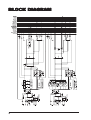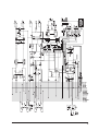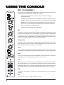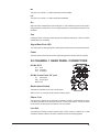
1
Music Mix
er
Mixer
User Guide
1
IMPORTANT
Please read this manual carefully before using
your mixer for the first time.
© Harman International Industries Ltd. 2005
All rights reserved
Parts of the design of this product may be protected by worldwide patents.
Part No. ZM0336-01
Soundcraft is a trading division of Harman International Industries Ltd. Information in this manual
is subject to change without notice and does not represent a commitment on the part of the
vendor. Soundcraft shall not be liable for any loss or damage whatsoever arising from the use of
information or any error contained in this manual.
No part of this manual may be reproduced, stored in a retrieval system, or transmitted, in any
form or by any means, electronic, electrical, mechanical, optical, chemical, including photocopying
and recording, for any purpose without the express written permission of Soundcraft.
Harman International Industries Limited
Cranborne House
Cranborne Road
POTTERS BAR
Hertfordshire
EN6 3JN
UK
Tel:
+44 (0)1707 665000
Fax: +44 (0)1707 660742
http://www.ureidj.com
2
Contents
IMPORTANT SAFETY INSTRUCTIONS
SAFETY SYMBOL GUIDE
4
6
INTRODUCTION
7
7
INSTALLATION
GENERAL PRECAUTIONS
MAINS INSTALLATION
INITIAL WIRING CONSIDERATIONS
AUDIO WIRING
SHIELDING
POINTS TO REMEMBER
WORKING SAFELY WITH SOUND
INSPECTION AND INSTALLATION
MAKING ADJUSTMENTS AND FITTING SPARES
MOVING THE REAR CONNECTOR PANEL
REPOSITIONING THE RACK EARS
ENABLING THE EXTERNAL MUTE FEATURE
CONNECTING TO A TYPICAL SOUND SYSTEM
8
8
8
9
9
9
10
10
11
12
14
14
14
15
BLOCK DIAGRAM
16
USING THE CONSOLE
18
MIC / DJ CHANNEL 1
DJ CHANNEL 1 REAR PANEL CONNECTORS
CHANNELS 2-7 (2-4 ON 1603)
CHANNELS 2-7 (2-4 ON 1603) REAR PANEL CONNECTORS
MASTER SECTION
EXTERNAL MUTE OPERATION
18
19
20
21
22
25
SPECIFICATIONS
26
GLOSSARY
28
WARRANTY
31
3
IMPORTANT SAFETY INSTRUCTIONS
Read these instructions.
Keep these instructions.
Heed all warnings.
Follow all instructions.
Do not use this apparatus near water.
Clean only with a dry cloth.
Do not block any ventilation openings. Install in accordance with the manufacturer’s instructions.
Do not install near any heat sources such as radiators, heat registers, stoves, or other apparatus (including
amplifiers) that produce heat.
Do not defeat the safety purpose of a polarised or grounding type plug. A polarised plug has two blades with one
wider than the other. A grounding type plug has two blades and a third grounding prong. The wide blade or the
third prong are provided for your safety. If the provided plug does not fit into your outlet, consult an electrician for
replacement of the obsolete outlet
Protect the power cord from being walked on or pinched particularly at plugs, convenience receptacles and the
point where they exit from the apparatus.
Only use attachments/accessories specified by the manufacturer.
Use only with the cart, stand, tripod, bracket or table specified by the manufacturer, or sold with the apparatus.
When a cart is used, use caution when moving the cart/apparatus combination to avoid injury from tip-over.
Unplug this apparatus during lightning storms or when unused for long periods of time.
Refer all servicing to qualified service personnel. Servicing is required when the apparatus has been damaged
in any way, such as power-supply cord or plug is damaged, liquid has been spilled or objects fallen into the
apparatus, the apparatus has been exposed to rain or moisture, does not operate normally, or has been dropped.
4
Note: It is recommended that all maintenance and service on the product should be carried out by Soundcraft or its
authorised agents. Soundcraft cannot accept any liability whatsoever for any loss or damage caused by service,
maintenance or repair by unauthorised personnel.
WARNING: To reduce the risk of fire or electric shock, do not expose this apparatus to rain or moisture.
Do not expose the apparatus to dripping or splashing and do not place objects filled with liquids, such as vases, on
the apparatus.
No naked flame sources, such as lighted candles, should be placed on the apparatus.
Ventilation should not be impeded by covering the ventilation openings with items such as newspapers, table
cloths, curtains etc.
THIS APPARATUS MUST BE EARTHED. Under no circumstances should the safety earth be disconnected from
the mains lead.
The mains supply disconnect device is the mains plug. It must remain accessible so as to be readily operable when
the apparatus is in use.
If any part of the mains cord set is damaged, the complete cord set should be replaced. The following information
is for reference only.
The wires in the mains lead are coloured in accordance with the following code:
Earth (Ground):
Green and Yellow (US - Green/Yellow)
Neutral:
Blue (US - White)
Live (Hot):
Brown (US - Black)
As the colours of the wires in the mains lead may not correspond with the coloured markings identifying the
terminals in your plug, proceed as follows:
The wire which is coloured Green and Yellow must be connected to the terminal in the plug which is
marked with the letter E or by the earth symbol.
The wire which is coloured Blue must be connected to the terminal in the plug which is marked with the
letter N
The wire which is coloured Brown must be connected to the terminal in the plug which is marked with
the letter L
Ensure that these colour codes are followed carefully in the event of the plug being changed
This unit is capable of operating over a range of mains voltages as marked on the rear panel.
NOTE: This equipment has been tested and found to comply with the limits for a Class A digital device, pursuant to
Part 15 of the FCC Rules. These limits are designed to provide reasonable protection against harmful interference
when the equipment is operated in a commercial environment. This equipment generates, uses and can radiate
radio frequency energy and, if not installed and used in accordance with the instruction manual, may cause harmful
interference to radio communications. Operation of this equipment in a residential area is likely to cause harmful
interference in which case the user will be required to correct the interference at his own expense.
This Class A digital apparatus meets the requirements of the Canadian Interference-Causing Equipment Regulations.
Cet appareil numérique de la Classe A respecte toutes les exigences du Règlement sur le matériel brouilleur du
Canada.
5
For your own safety and to avoid invalidation of the
warranty please read this section carefully.
SAFETY SYMBOL GUIDE
For your own safety and to avoid invalidation of the warranty all text marked with these symbols
should be read carefully.
WARNINGS
The lightning flash with arr
owhead symbol, is
arrowhead
intended to aler
esence of unalertt the user to the pr
presence
insulated “danger
ous voltage” within the pr
oduct’s
“dangerous
product’s
enclosur
e that may be of suf
ficient magnitude to
enclosure
sufficient
constitute a risk of electric shock to persons.
CAUTIONS
The exclamation point within an equilateral triangle
is intended to aler
esence of
alertt the user to the pr
presence
impor
tant operating and maintenance (servicing)
important
instructions in the literatur
e accompanying the
literature
appliance.
NOTES
Contain impor
tant infor
mation and useful tips on the
important
information
operation of your equipment.
HEADPHONES SAFETY WARNING
Contain impor
tant infor
mation and useful tips on
important
information
headphone outputs and monitoring levels.
Recommended Headphone Impedance >= 200 Ohms.
6
INTR
ODUCTION
INTRODUCTION
Welcome
Thanks for purchasing a UREI by Soundcraft 1603/1605 mixer, we hope you get just as much joy from using it as we got from
designing it.
The UREI by Soundcraft engineering team have 30 years experience in progressive audio design and take the utmost pride in the
way we develop and manufacture products.
Our consoles are in use 24 hours a day, every day all around the globe performing flawlessly by the most demanding industry
professionals.
Registering Your Mixer
Please take this opportunity to register the purchase of your mixer with Urei By Soundcraft. You can do this by filling in the pre-paid
postcard included in the packaging, or by going online to www.ureidj.com/registration.
Urei by Soundcraft recommends AKG Professional Dj Headphones.
Please visit www.akg.com/dj for more information.
7
INST
ALLA
TION
INSTALLA
ALLATION
The 1605/1603 is ruggedly constructed with the highest quality components. As such, it should provide years of trouble free use
with normal care. All parts used are conservatively rated for their application, and workmanship meets UREI by Soundcraft’s rigid
standards.
NO SPECIAL PREVENTIVE MAINTENANCE IS REQUIRED, AND (WITH THE
EXCEPTION OF THE PRE-TRIM ATTENUATORS) THERE ARE NO INTERNAL
SERVICE ADJUSTMENTS.
GENERAL PRECAUTIONS
Avoid storing or using the mixing console in conditions of excessive heat or cold, or in positions where it is likely to be subject to
vibration, dust or moisture. Do not use any liquids to clean the fascia of the unit: a soft dry cloth is ideal.
Avoid using the console close to strong sources of electromagnetic radiation (e.g. video monitors, high-power electric cabling): this
may cause degradation of the audio quality due to induced voltages in connecting leads and chassis.
Caution! In all cases, refer servicing to qualified personnel.
Handling and Transport
The console is supplied in a strong carton. If it is necessary to move it any distance after installation it is recommended that this
packing is used to protect it. Be sure to disconnect all cabling before moving. If the console is to be regularly moved we recommend
that it is installed in a foam lined flightcase. At all times avoid applying excessive force to any knobs, switches or connectors.
Power Cable
Always use the power supply cable supplied with the mixer: the use of alternative cables may cause damage and voids the warranty.
Warning ! In the event of an electrical storm, or large mains voltage fluctuations,
immediately unplug from the mains.
Signal Levels
It is important to supply the correct input levels to the console, otherwise signal to noise ratio or distortion performance may be
degraded; and in extreme cases, damage to the internal circuitry may result. Likewise, on all balanced inputs avoid sources with
large common mode DC, AC or RF voltages, as these will reduce the available signal range on the inputs. Note that OdBu =0.775V
RMS.
Refer to the Specifications section for details of input and output levels.
MAINS INSTALLATION
General Wiring Procedures
To take full advantage of the excellent signal to noise ratio and low distortion of Soundcraft consoles, care must be taken to ensure
that incorrect installation and wiring does not degrade the performance of the desk. Hum, buzz, instability and Radio Frequency
interference can usually be traced to earth loops and inferior earthing systems. In some areas, especially heavily industrial areas,
the incoming mains earth will not be adequate and a separate technical earth for all the audio equipment must be supplied.
However, check with your local electricity supply company to ensure that safety regulations are not infringed or negated.
The successful, hum free, installation of a system requires forethought, and the establishment of a set of ground rules, which must
be consistently adhered to at all stages of installation.
8
INITIAL WIRING CONSIDERATIONS
For optimum performance, it is essential for the earthing system to be clean and noise free, as all signals are referenced to this
earth. A central point should be decided on for the main earth point system, and all earths should be 'star fed' from this point. It is
common electrical practice to `daisy chain' the earths to all electrical outlets but this method is unsuitable for audio installations. The
preferred method is to run an individual earth wire from each outlet, back to the system star point to provide a safety earth screen
reference for each piece of equipment. A separate earth wire should also be run from each equipment rack and area, to the star
point. This may or may not be used depending on circumstances, but it is easier to install in the first place, than later when problems
arise. The location of the star point should be a convenient, easily accessible place, preferably at the rear of the console or in the
main equipment rack.
Install separate 'clean' and 'dirty' mains outlets, wired individually back to the incoming mains distribution box. Use the 'clean' supply
for all audio equipment and the `dirty' supply for all lighting, etc. Never mix the two systems.
If necessary, to provide sufficient isolation from mains interference on the booth output, install an isolating transformer. This should
be provided with a Faraday Shield which must be connected with earth.
Never locate the incoming mains distribution box near audio equipment, especially tape recorders, which are very sensitive to
electromagnetic fields.
Ensure that all equipment racks are connected to earth, via a separate wire back to the star point.
Equipment which has balanced/unbalanced inputs and outputs may need to be electrically isolated from the equipment rack and/or
other equipment, to avoid earth loops.
AUDIO WIRING
Having provided all equipment with power and earthing connections, consideration must be given to the method of providing audio
interconnection and adequate screening of those interconnections. This must be done in a logical sequence to avoid problems and
assist in the localisation of problem equipment.
Connect the Main or Booth system to the console and check for any hum, buzz, or RFI. Only when you are satisfied with the
quietness of the console and the PA system should you proceed with the next step.
Connect decks or CD players, FX and sends one at a time, checking and isolating any connection which degrades performance.
Connect all other peripheral devices.
Connect all microphone lines.
By following this sequence much time and future trouble will be saved, and the result will be a quiet, stable system.
SHIELDING
Audio equipment is supplied with a variety of input and output configurations, which must be taken into consideration when deciding
where the screen connections should be made. There are three sources of unwanted signal being impressed on the screen, which
are as follows:
Extraneous electrostatic or electromagnetic fields.
Noise and interference on the earth line.
Capacitive coupling between the screen and signal wires.
Therefore, in general, always connect the shield only at the signal source end. In high RF areas, the screen can also be connected
to earth via a 0.01 mF capacitor. This will present a short circuit at RF frequencies, thus lowering the effective shield impedance to
ground. However, at low audio frequencies the capacitor will effectively be an open circuit and thus not cause an earth loop problem.
9
POINTS TO REMEMBER
When using balanced connections use good quality twin screened audio cable. Check for instability at the output.
Always connect both conductors at both ends, and ensure that the screen is only connected at one end.
Do not disconnect the mains earth from each piece of equipment. This is needed to provide both safety and screen returns to the
system star point.
It is important to remember that all equipment which is connected to the mains is a potential source of hum and interference and
may radiate both electrostatic or electromagnetic radiation. In addition, the mains will also act as a carrier for many forms of RF
interference generated by electric motors, air-conditioning units, thyristor light dimmers etc. Unless the earth system is clean, all
attempts to improve hum noise levels will be futile. In extreme cases there will be no alternative but to provide a completely separate
and independent `technical earth' to replace the incoming 'noisy earth'. However, always consult your local electricity supply authority
to ensure that safety regulations are not being infringed.
WORKING SAFELY WITH SOUND
Although your new console will not make any noise until you feed it signals, it has the capability to produce sounds which when
monitored through an amplifier or headphones can damage hearing. Always turn amplifiers down when turning your console on or
off.
The table below is taken from the Occupational Safety & Health Administration directive on Occupational noise exposure (1926.52):
PERMISSIBLE NOISE EXPOSURE
DURATION PER DAY, HOURS
8
6
4
3
2
1.5
1
0.5
<0.25
SOUND LEVEL dBA SLOW RESPONSE
90
92
95
97
100
102
105
110
115
Conforming to this directive will minimise the risk of hearing damage caused by long listening periods. A simple rule to follow is the
longer you listen the lower the average volume should be.
Please take care when working with your audio - if you are manipulating controls which you don’t understand (which we all do when
we are learning), make sure your monitors are turned down. Remember that your ears are the most important tool of your trade, look
after them, and they will look after you.
Most importantly - don’t be afraid to experiment to find out how each parameter affects the sound - this will extend your creativity and
help you to get the best results.
Recommended Headphone Impedance >= 200 Ohms
10
INSPECTION AND INSTALLATION
UNPACKING AND INSPECTION
Your 1605/1603 was carefully packed at the factory, and the container was designed to protect the unit from rough handling.
Nevertheless, we recommend careful examination of the shipping carton and its contents for any sign of physical damage which
could have occurred in transit.
If damage is evident, do not destroy any of the packing material or the carton, and immediately notify the carrier of a possible claim
for damage. Shipping claims must be made by the consignee.
The carton should contain:
Model 1605/1603 Music Mixer.
Mains Cable
UREI Instruction Manual (this book).
Warranty Card (the serial number tag is on the base panel of the Mixer).
2mm Allen key
ENVIRONMENTAL CONSIDERATIONS
The 1605/1603 Mixer will operate satisfactorily over a range of ambient temperatures from 0 C to +50C (+32F to +122F), and up to
80% non-condensing relative humidity.
If the system is installed in an equipment rack, console or desk with high heat producing equipment (such as power amplifiers),
adequate ventilation should be provided in order to assure longest component life. Also, while circuitry susceptible to hum pick-up
is sufficiently shielded from moderate electromagnetic fields, installation should be planned to avoid mounting the system immediately
adjacent to large power transformers, motors, etc.
POWERING
The 1605/1603 may be operated from 100-250V AC mains (50-60 Hz, single phase). BE SURE TO VERIFY LINE VOLTAGE
BEFORE CONNECTING THE 1605/1603 TO THE MAINS.
Please Note. The IEC mains connector is fitted with a retaining clip to prevent the mains lead from accidentally being
pulled out during operation. To ensure that this clip will fit correctly, the lead supplied with the mixer must be used.
11
MAKING ADJUSTMENTS AND FITTING SPARES
CAUTION: THE FOLLOWING SECTION IS FOR USE BY QUALIFIED
SERVICE PERSONNEL ONLY. TO REDUCE THE RISK OF ELECTRIC
SHOCK, DO NOT REMOVE THE TOP FASCIA OR THE FADER PANEL TO
PERFORM ANY SERVICING OR OTHER TASKS, UNLESS YOU ARE
QUALIFIED TO DO SO.
BEFORE REMOVING THE TOP FASCIA OR THE FADER PANEL ENSURE
THE UNIT IS DISCONNECTED FROM THE MAINS SUPPLY.
ONLY REMOVE THE ALLEN SCREWS INDICATED ON THE DIAGRAM OPPOSITE.
WARNING: DO NOT OVER-TIGHTEN THE SCREWS AFTERWARDS.
It is necessary to remove the top panel fascia in order to carry out one or more of the following tasks:
Setting the pre-trim pads during installation, and setting of the gain stages / output pads.
Adjusting the external mute mic level control
It is necessary to remove the fader panel only in order to replace any of the faders, including the cross-fader.
Removing The Top Panel Fascia
To remove the top panel fascia proceed as follows:
Pull off all the pot knobs.
Undo the 9 (for 1605) or 8 (for 1603) retaining Allen screws using a 2mm Allen key. The fascia can now be lifted clear of
the subframe underneath. Take care not to bend the panel.
The diagrams opposite show views of the 1605 mixer without top fascias fitted. The 1603 is similar but has fewer retaining screws.
Setting The Pre-trim Gain Stages
These pads are used to adjust the input level to individual channels, e.g. to reduce the input when using a piece of equipment with
a high output level.
There are 2 pads on each of the input channels. The +14dB gain stage switch is nearest to the faders, and the -10dB pad is nearest
to the rear panel. The switches are push-on push-off types. The pads are in-circuit when the switches are depressed.
If both switches are inadvertently depressed the -10dB pad is selected. The +14dB selection is designed to boost the signal from
low level portable devices such as mp3 players.
Setting The Master Output Pads
There are two pads on the master outputs, -10dB and -20dB. Depress the -10dB to select the -10dB pad, depress both switches to
select the-20dB pad: if only the -20dB switch is depressed no pad will be selected.
Adjusting The External Mute Mic Level Control
If the external mute facility is going to be used, the installation engineer can check and adjust the level at which the DJ channel 1 mic
signal will appear at the master outputs. To simulate an external mute condition depress the mute test button. The main output will
then only be the output from DJ channel 1. Under the external mute condition its level at the output is unaffected by any mixer control
except for the preset ext mute mic level pot. When the pot is fully anti-clockwise the mute the signal.
Removing The Fader Panel
To remove the top panel fascia proceed as follows:
Pull off the cross-fader knob only (the channel faders are attached to the panel and will lift away with it).
12
Undo the 7 (1605) or 6 (1603) Allen screws using a 2mm Allen key. The fader panel can now be lifted clear of the
subframe underneath. Take care not to bend the panel.
Replacing The Channel Faders
Using a 2mm Allen key undo and remove the 2 screws which secure the fader to the fader panel. Unplug the 8-pin connector,
appying slight lateral force to the plug from side to side as you pull the plug from the socket. Plug the connector into the new
fader. The connector is keyed so that it cannot be inserted the wrong way round. Carefully place the new fader back into the fader
panel and secure with the screws removed earlier, DO NOT OVER-TIGHTEN THE SCREWS.
Replacing The Cross- Fader
Using a pozi-screwdriver undo and remove the screws which secure the fader mounting plate to the subframe. Carefully withdraw
the fader, taking care not to damage the wiring harness that is attached to it. Unplug the 6-pin connector, wiggle the plug from side
to side as you pull the plug from the socket. Plug the connector into the new fader. The connector is keyed so that it cannot be
inserted the wrong way round. Carefully place the new fader back into the subframe and secure with the screws removed earlier,
DO NOT OVER-TIGHTEN THE SCREWS. NOTE:Ensure the PCB extrusion is facing the channel faders when replacing the cross
fader.
Replaceable Spares Part Numbers
RS2432 - Urei 1603/5 Crossfader
RS2433 - Urei 1603/5 Channel Fader
13
MOVING THE REAR CONNECTOR PANEL
It is possible to move the rear connector panel from its factory default position to its alternative location underneath the console. This
alternative position can make it easier to rack or furniture-mount the console. To move the rear connector panel proceed as shown
in the following diagram.
REPOSITIONING THE RACK EARS
The rack ears are shipped fitted to the sides of the console, but they are upside-down with the ears tucked underneath the
console. To reposition them to allow furniture/rack fitting proceed as follows:
Note that the ears are not identical, there is left hand and a right hand ear. It is best to reposition one side completely before
starting on the other one. Undo the 8 screws which hold the ear onto the side of the console. Rotate the ear so that it is level with
the top of the console and is facing outwards. Replace the 8 screws. Repeat this operation for the other ear.
ENABLING THE EXTERNAL MUTE FEATURE
The factory default is that this feature is disabled. There is therefore no need to fit a shorting wire between the two n.c. (normally
closed) contacts if you do not want to use this feature.
To enable this feature the internal switch which shorts the two n.c. contacts must be opened. Before doing this ensure that the
mains is switched off and the mains lead is removed from the mixer.
Remove the rear panel as described in the instuctions above (moving the rear
connector panel). This will allow access to the internal switch.
The switch is located on a small pcb which is behind the red external mute connector,
The switch must be depressed to enable the exturnal mute reature. The switch is a
push-on, push-off type.
Replace the rear connectior panel and secure with the screws removed earlier.
A user-provided external-mute switch must be wired between the two rear panel
contacts as shown.
14
CONNECTING TO A TYPICAL SOUND SYSTEM
The diagram below shows how to connect the different parts of a typical sound system.
15
BL
OCK DIA
GRAM
BLOCK
DIAGRAM
16
17
USING THE CONSOLE
MIC / DJ CHANNEL 1
The Channel 1 has a slightly different arrangement from the other input channels. There are four
differences between this channel and all of the others. They are:
The mic input to this channel can be made to form part of a venue’s emergency
announcement system.
The output from the channel’s fader is routed directly to the master output buses rather
than the A or B buses. This means that the output is never routed through the cross-fader.
When the mic input is selected the output can be blocked from being routed onto the DJ
booth buses. If this mode of operation is selected it prevents howlround in the DJ booth.
The EQ is a conventional +/-12dB 3-band type.
THe channel must be activated using the ON switch.
Mic
This switch is a ‘push on, push off’ type. When this switch is pushed down, the MIC input on the rear
connector panel is selected. A LED* in the switch lights up to show that the mic is selected. When
the switch is in the ‘up’ position the phone or line input is selected (dependiing on the position of the
phono/line switch). (Note: if the MIC switch is not selected this LED will flash if the eternal mute is
activated. This shows that the mic is now routed to the master outputs.)
Phone/Line
This switch is a ‘push on, push off’ type. It routes the signal from the line input when it is ‘up’, and the
phono input when it is ‘down’, The LED in the switch lights when the phono input is selected. This
switch only operates when the mic switch is in the ‘up’ position.
Trim
This control gives a range adjustment of 32dB [+12/-20 for the Line/Phono and +20/-12 for the mic].
This allows you to adjust the input level to provide comparable levels on all of the channels’ faders.
Aux
The Aux pot controls the level of the channel’s signal which is sent to the aux buses. The signal can
be pre-fade or post fade, depending upon the position of the Pre switch.
Pre
When the pre switch is in the ’down’ position, a pre-fade signal is sent to the Aux buses. This means
that the signal level sent to the aux buses does not depend on the position of the channel’s fader.
When the pre switch is in the ’up’ position, a post-fade signal is sent to the aux buses. This means
that the signal level sent to the aux buses also depends on the position of the channel’s fader.
EQ
The three EQ controls allow you to apply a cut or boost to different parts of the audio-frequency
spectrum.
High
This gives a cut or boost of +/-12dB to frequencies over 8kHz
18
Mid
This gives a cut or boost of +/-12dB to frequencies centred at 600Hz
Low
This gives a cut or boost of +/-12dB to frequencies below 60Hz
On
When this switch is depressed its internal LED lights up. This indicates that the channel’s signal is
being routed to the master section. The cue signal (see below) is not affected by the position of the
ON switch.
Cue
Pressing this button routes the pre-fader signal to the headphones and meters. A LED in the switch
indicates when Cue is selected.
Signal-Beat-Peak LED
This LED is green to show signal present, yellow flashes show the beat, and red shows overload.
Fader
The fader controls the level of the channel’s signal being fed to the master buses (left and right).
DJ CHANNEL 1 REAR PANEL CONNECTORS
DJ Mic XLR
Pin 1 Gnd
Pin 2 Hot signal
Pin3 Cold signal
DJ Mic Insert Point 1/4” jack
Tip
Send signal
Ring Return signal
Sleeve Gnd
Booth defeat Switch
This switch is accessible via the hole in the rear panel.
When it is set to ‘on’ the dj mic will be routed to the booth outputs.
Phono Pair
This stereo pair of sockets has an RIAA filter for turntables. This filter is activated when the Phono/
Line switch, accessible via the hole in the rear panel, is in the ‘phono’ position. This pair of sockets
can be used for line level inputs if the switch is in the ‘line’ position
Line Pair
This stereo pair of sockets is used for line level inputs. There is a boost of +14dB or cut of -10dB
available via switches under the top fascia. These will be set by the installing engineer.
19
CHANNELS 2-7 (2-4 ON 1603)
Mic
This switch is a ‘push on, push off’ type. When this switch is pushed down, the MIC input on the rear
connector panel is selected. A LED in the switch lights up to show that the mic is selected. When the
switch is in the ‘up’ position the phono or line input is selected (dependiing on the position of the
phono/line switch).
Phono/Line
This switch is a ‘push on, push off’ type. It routes the signal from the line input when it is ‘up’, and the
phono input when it is ‘down’, The LED in the switch lights when the phono input is selected. This
switch only operates when the mic switch is in the ‘up’ position.
Trim
This control gives a range adjustment of 32dB [+12/-20 for the Line/Phono and +20/-12 for the mic].
This allows you to adjust the input level to provide comparable levels on all of the channels’ faders.
Aux
The Aux pot controls the level of the channel’s signal which is sent to the aux buses. The signal can
be pre-fade or post fade, depending upon the position of the Pre switch.
Pre
When the pre switch is in the ’down’ position, a pre-fade signal is sent to the Aux buses. This means
that the signal level sent to the aux buses does not depend on the position of the channel’s fader.
When the pre switch is in the ’up’ position, a post-fade signal is sent to the aux buses. This means
that the signal level sent to the aux buses also depends on the position of the channel’s fader.
EQ
The three EQ controls allow you to apply a cut or boost to different parts of the audio-frequency
spectrum.
High (Pass Filter)
This gives from a full cut to a boost of +6dB to frequencies at or over 3.5kHz.
Mid (Band Pass Filter)
This gives a from a full cut to a boost of +6dB to frequencies between 300Hz-3.5kHz (bandwidth).
Low (Pass Filter)
This gives from a full cut to a boost of +6dB to frequencies at or below 300Hz.
This isolator eq design gives an advantage over a conventional eq: the unity gain point is not at the
centre of the pot travel. This gives the user more controln resolution over the cut part of the range,
exactly where it is needed.
A/Master/B Switch
This 3-position switch routes the channel’s post-fader output signal to one of three pairs of stereo
buses. If the Master position is selected the post-fader signal is routed diretly to the booth and
master outputs. If the A or B position is selected then the output is routed via the cross fader.
20
Cue
Pressing this button routes the pre-fader signal to the headphones and meters. A LED in the switch
indicates when Cue is selected.
Signal-Beat-Peak LED
This LED is green to show when a signal is present, yellow flashes show the beat, and red shows
overload.
Fader
The fader controls the level of the channel’s signal being fed to the A/Master/B selector switch.
CHANNELS 2-7 (2-4 ON 1603) REAR PANEL
CONNECTORS
Mic XLR
Pin 1 Gnd
Pin 2 Hot signal
Pin3 Cold signal
Phono Pair
This stereo pair of sockets has an RIAA filter for turntables. This filter is activated when the Phono/
Line switch, accessible via the hole in the rear panel, is in the ‘phono’ position. This pair of sockets
can be used for line level inputs if the switch is in the ‘line’ position
Line Pair
This stereo pair of sockets is used for line level inputs. There is a boost of +14dB or cut of -10dB
available via switches under the top fascia. These will be set by the installing engineer.
Ground Point
This is for use with turntables which require a ground lead.
21
MASTER SECTION
22
Meters
The L & R bargraph meters show, by default, the signal levels at the Master Left and Right outputs.
If any Cue switch on the desk is pressed the meters display the level of the cued signal.
Split Switch
If the Split switch is depressed the meters will show a mono sum of the cued signal on the left meter, and a mono sum of the prefader master outputs on the right meter. Note that the split button has no effect on the meter display until a cue button is pressed.
Aux Send/Return
This section allows the use of an external effects unit. NOTE: It can also be used as an alternative record output and an additonal
stereo input.
Send Outputs
The stereo pair of sockets feeds signals from the the Aux left & right buses. The level is controled via the level pot. The post-pot
signal can be monitored via its associated cue switch.
Return Inputs
The stereo pair of sockets is used to input a feed from an external effects unit. The signal can be monitored via its cue switch. The
signal is controlled via the on switch (note that the cue switch is before the on switch in the signal path). The level of the signal is
controlled by the level pot. The post-pot signal is assignable to the cross fader via the A/Master/B switch
A/Master/B Switch
This 3-position switch routes the return signal to one of three pairs of stereo buses. If the Master position is selected the signal is
routed diretly to the booth and master outputs. If the A or B position is selected then the signal is routed via the cross fader.
Master
HPF
The high-pass filter is selected by depressing the hpf switch. This affects the master and the booth outputs.
Mono
This switch, when depressed, sums the stereo signal to a mono signal. This affects the master and the booth outputs.
Balance
The balance controls allows the left/right balance of a stereo signal to be adjusted.
Level
The level of the master outputs is controlled via this pot.
Cue
Pressing this button routes the pre-level-control signal to the headphones and meters. A LED in the switch indicates when Cue is
selected.
23
Booth
EQ
The booth eq has two bands. Both controls give a cut/boost of +/-6dB.
Level
The level of the booth outputs is controlled via this pot.
Left/Stereo/Right
This 3-position works as follows:
left: mono signal is fed to booth left ouput only
stereo: normal stereo
right: mono signal is fed to booth right ouput only
Dim
When depressed this switch causes the booth outputs to be cut by 12dB.
XF Curve
The XF Curve pot allows the cross-fader law to be varied from ‘constant power’ mode to ‘performance/scratch’ mode.
Headphones
In normal mode the headphones circuit monitors the master left & right outputs. A cue switch anywhere on the desk is pressed the
headphones will monitor the appropriate signal.
Level
The level pot controls the signal level sent to the headphones.
EQ
The single eq pot varies the headphones between dark and bright characteristics. Dark = treble cut and Bright = bass cut.
Balance Pot
The balance pot allows adjustment of the left/right balance of the stereo headphone signal. In split mode the balance pot becomes
a mono cue/main pan control. In cue mode the balance control becomes a stereo cue/main balance control.
Split Mode
The split button, when depressed, activates split mode. in split mode the the cue-sum (cue L+R) goes to the left headphone, and the
main-sum goes to the right headphone. This only operates when a cue switch is pressed. The balance pot becomes a cue/main pan
control.
Flip Mode
This reverses the left/right feeds in split mode. Flip mode only operates within split mode.
Sockets
There are two sockets: a 1/4” (6.35mm) and a 3.5mm socket. This allows the use of both types of plug without the need for adaptors.
It is not intended that two sets of headphones be connected at the same time.
24
EXTERNAL MUTE OPERATION
If the external mute mode is enabled the following happens when the n.c. link on the rear of the console goes open circuit:
The pre-insert signal from the mic on channel 1 is routed directly to the master outputs, bypassing all level controls and
eq controls. Its level is set only by the pre-set level control underneath the top fascia.
The channel 1 mic signal will be shown on the meters.
The channel 1 mic signal will be routed to the headphones.
All other music or mic signals to the master outputs will be cut.
The booth outputs will be cut.
All the Signal-Beat-Peak LEDS flash red.
The LED in the MIC switch on channel 1 will flash if mic is not selected.
25
SPECIFICA
TIONS
SPECIFICATIONS
Input and Output Levels
XLR INPUT (electronically balanced) Mic
Gain range ............................................................................................................. +22~+54dB with +20db/-12dB gain trim
Maximum input level ................................................................................................................................................. -14dBu
Input impedance ..................................................................................................................................................... 2k ohms
INSERT SEND (unbalanced, Ch1 only)
Nominal level ............................................................................................................................................................... 0dBu
Maximum output level ......................................................................................................................... +20dBu into 2k ohms
Output impedance ................................................................................................................................................... 75 ohms
INSERT RETURN (unbalanced, Ch1 only)
Maximum input level ................................................................................................................................................ +20dBu
Input impedance ................................................................................................................................................. >50k ohms
PHONO/LINE INPUT (unbalanced)
Nominal level ................................................................................................................................................................0dbu
Trim ...................................................................................................................................................................... +12/-20db
Max input level ......................................................................................................................................................... +20dbu
Input impedance ................................................................................................................................................... 45k ohms
Rear Panel Connector connections
XLR INPUT & OUTPUT (3 pin female XLR)
Pin 1 .......................................................................................................................................................................... Ground
Pin 2 ..................................................................................................................................................................... Signal Hot
Pin 3 ................................................................................................................................................................... Signal Cold
INSERT SEND and RETURN (1/4" TSR Jack) MIC 1 Only
Tip ................................................................................................................................................................................ Send
Ring ........................................................................................................................................................................... Return
Sleeve ....................................................................................................................................................................... Ground
PHONO and 1/4” JACKS
Tip ................................................................................................................................................................................... Hot
Sleeve ....................................................................................................................................................................... Screen
Master/Booth Output
High Pass Filter .................................................................................................................................. 18dB/Octave @ 63Hz
Output Impedance .................................................................................................................................................. 75 ohms
Recommended Load ............................................................................................................................ 600 ohms or greater
Frequency Response .......................................................................................................................... +/- 1dB, 20Hz-20kHz
Distortion .................................................................................................................. < 0.05% THD, 20Hz-20kHz @ +16dbu
Maximum Output ................................................................................................................................. +20dB into 600 ohms
Headphone Output
Output Impedance ................................................................................................................................................ <40 ohms
Recommended Load ............................................................................................................................ 150 ohms or greater
Frequency Response ........................................................................................... +0, -1dB, 20Hz-20kHz into 200 ohm load
Distortion ................................................................................................................. < 0.05% THD, 20Hz-20kHz @ +16dBu
Maximum Output ............................................................................................................................... 190mW into 150 ohms
26
Mono Output
Output Impedance .................................................................................................................................................. 75 ohms
Recommended Load .............................................................................................................................. 2k ohms or greater
Frequency Response .......................................................................................................................... +/- 1dB, 20Hz-20kHz
Distortion ................................................................................................................. < 0.05% THD, 20Hz-20kHz @ +16dBu
Maximum Output ................................................................................................................................. +20dBu into 2k ohms
Effects Loop Output
Output Impedance ................................................................................................................................................ 75k ohms
Recommended Load .............................................................................................................................. 5k ohms or greater
Frequency Response .......................................................................................................................... +/- 1dB, 20Hz-20kHz
Distortion ................................................................................................................. < 0.05% THD, 20Hz-20kHz @ +16dBu
Maximum Output ................................................................................................................................... +20dB into 2k ohms
Noise
All channels routed at unity, mix at unity .................................................................................................................. < -85dB
Crosstalk (@1kHz) ................................................................................................................................................... < -85dB
Channel Mute
Fader Cut-off (rel. 0 Mark) ....................................................................................................................................... < -95dB
FX Sends offness ..................................................................................................................................................... < -90dB
Input and Output Impedance
Mic Input ................................................................................................................................................................. 2k ohms
Line Input .............................................................................................................................................................. 45k ohms
Aux Input (Unbalanced RCA Phono) ..................................................................................................................... 30k ohms
Master/booth Output ............................................................................................................................................... 75 ohms
Aux Output .............................................................................................................................................................. 75 ohms
Headphones Output ................................................................................................................................................ 40 ohms
Maximum Output Levels
Insert Send Output .............................................................................................................................. +20dBu into 2k ohms
Mix Output ........................................................................................................................................ +20dBu into 600 ohms
Aux Output .......................................................................................................................................... +20dBu into 2k ohms
Booth Output ..................................................................................................................................... +20dBu into 600 ohms
Headphones Output .......................................................................................................................... +20dBu into 300 ohms
Headphones ...................................................................................................................................... 190mW into 150 ohms
Dimensions/ weight
1605
Without rack ears .............................................................................................................. 87.6(H) x 440(W) x 400(D) (mm)
With rack ears ................................................................................................................... 87.6(H) x 483(W) x 400(D) (mm)
Weight ......................................................................................................................................................... 8.7kgs/ 19.1 lbs
1603
Without rack ears .............................................................................................................. 87.6(H) x 338(W) x 400(D) (mm)
With rack ears ................................................................................................................... 87.6(H) x 381(W) x 400(D) (mm)
Weight ......................................................................................................................................................... 7.5kgs/ 16.5 lbs
27
GL
OSSAR
Y
GLOSSAR
OSSARY
Amplitude:
Another term used for signal level.
Attenuate:
Reduce the signal level.
Attenuator:
A device which reduces the signal level.
Auxiliary (Aux):
An independent mix derived from the channels for various functions. This can be set pre (before) or
post (after) the channel fader.
Balanced, Unbalanced:
Refers to the type of input or output signal connection. An unbalanced connection has two signal
carrying conductors, one of which is the cable shield. A balanced connection has three conductors,
two for signal and a shield which is connected to earth. Because the signal conductors are at the
same impedance and of opposite polarity they are better able to cancel and therefore reject
interference and noise pickup. It is standard practice to use balanced connections for long cable runs,
for example to amplifiers, or cables carrying sensitive or low level signals, for example microphones.
Bandpass (BPF):
A filter with a bell-shaped response for attenuation of frequencies either side of the centre frequency.
Beat Mixing:
Using the variable pitch controls on turntables/CD players to synchronise the rhythm track of two
separate songs, so that the beat remains constant when smoothly cross-fading from one to the other.
Beats Per Minute (BPM): The measurement of the rhythmic beat or tempo of the music.
Booth:
The area, often enclosed, where the DJ operates. It is usually provided with local booth monitor
loudspeakers.
Cutting:
Moving the cross-fade control sharply from one side to the other, to cut u or pick out a sound, a hihat, kick drum etc, or to drop straight into another record. Also known as chopping.
Cartridge:
The pickup in a turntable. Uses a stylus to pick up vibrations from the record (vinyl) and convert this
to electrical signals that feed the console. The cartridge is usually fitted to a removable headshell that
plugs into the turntable arm.
Clipping:
The harsh distorted sound that results when the signal hits the maximum level possible.
Contour (Law, Curve):
The term used to describe the ‘law’ of a fader, how quickly it responds as it is moved, or the amount
of fade per unit of movement. The contour control associated with a fader lets the DJ tailor its
response to suit the preferred mixing style.
Cross-fader:
A horizontally operated fader for fading one music track in while fading the other out. Often used by
the DJ for cutting and layering sounds while mixing.
Cue (Solo):
A monitor system provided for the DJ to check individual channel signals using headphones while
lining up tracks ready to introduce into the mix.
Daisy-Chaining:
Connecting the output of one mixer to an input of another mixer.
dB (Decibel):
The unit of measurement for audio signal level. This is logarithmic to follow the response of the
human ear. ‘dB’ is a relative measurement to compare one level with another, for example gain from
input to output. ‘dBu’ is an absolute measurement referenced to a voltage standard where 0dBu =
0.775V rms. The console main outputs operate at 0dBu = ‘0’ reading on the meters. ‘’dBV’ is a similar
measurement but refers to a 1V standard. It is common for consumer equipment to operate a the
standard of –10dBV (316mV). ‘dBA’ refers to sound pressure level and is measured using the ‘A’
scale that ‘hears’ in the same way as the human ear.
Dynamic Range:
The difference expressed in dB between the highest and lowest signal levels possible. This is limited
by the clipping level and residual noise floor respectively.
Earth (Ground):
The term for the electronic signal reference. This generally connects to the mains supply earth point
and all cable shields and conductive equipment cases. It provides the return for the signal voltage
within the equipment. It also ensures operator safety by removing the possibility of electric shock
should the mains voltage touch any metal part.
28
Earth Loop (Ground Loop): The result when the equipment sees more than one path to the system earth. Current flows because
a resistive loop susceptible to radio and mains interference is formed. In severe cases this can result
in audible hum or buzz in the system. Breaking the loop by removing all but one path to earth usually
solves the problem.
EQ (Equaliser):
This provides cut or boost of selected frequencies (equalisation) for tonal shaping of the sound.
Feedback:
Also known as ‘howlround’ or ‘ringing’, this is the rapidly increasing tone produced when a
microphone picks up its own signal from the speakers. It is usually a shrill and annoying squeal that
should be quickly dealt with by repositioning the microphone or speakers, reducing mic gain or
equalising the system to notch out the offending frequencies.
Gain:
This is the boost or attenuation applied to the source signal in the channel preamp stage to match it
to the console operating level. For example, a large amount of gain is needed to match low
microphone signals. It is set using the console meters. Gain is not used for level (volume) control.
Headroom:
The amount of level available expressed in dB to handle peaks above the normal 0dB operating level.
Hz (Hertz):
The measurement of frequency. The audio spectrum ranges from a low (bass) frequency of 20Hz to a
high (treble) 20kHz.
Highpass filter (HPF):
A filter that attenuates frequencies below the cut-off frequency.
Hum:
This is the audible noise that usually results from mains interference pickup, earth loops, bad
interconnections and induced power supply and lighting fields. It is usually at mains frequency (50/
60Hz) or a related harmonic.
Impedance:
A technical term for the resistance of a signal conductor to ground. Low impedance (Low Z) usually
refers to microphones of 200 ohms or less, and line signals typically less than 100 ohms. Low Z
sources are less prone to interference pickup. Inputs are usually high impedance (High Z) so that one
source can connect to more than one channel without signal loss. Note that the operating impedance
of a connection is set by the impedance of the source, not that of the unconnected input.
Limiter:
A signal processor that limits the maximum level possible by preventing the signal going over a
predetermined threshold level. This is very useful in club installations where it is inserted between the
console and house system amplifiers to prevent the DJ exceeding the maximum allowable volume.
Lowpass filter (LPF):
A filter that attenuates frequencies above the cut-off frequency.
Mono:
A single source with no stereo content, or the left and right stereo signals summed together as one.
Mono Sum:
A mono signal which is the sum of the left and right parts of a stereo pair.
Mute (Cut):
To turn off the signal. Transform is a mute, or cut effect.
Noise:
Generic term for an unwanted signal. This may be residual electronic hiss, hum, buzz, clicks and
pops.
Noise Floor:
This is the term for the residual electronic noise produced by all powered audio equipment. It usually
sounds like a constant hiss, although some equipment may suffer from residual hum as well.
Omni-directional:
The response of a microphone which picks up sounds equally all round. Not suited to live vocal
applications as they are more prone to feed back.
Pad:
Another term for attenuator.
Pan (Panoramic):
A control that adjusts the balance of the signal in the left and right speakers.
Peak Meter:
A type of signal meter that has a very fast attack and slower release. This picks up the fast signal
transients and holds them long enough for the operator to see the activity on the display. These
meters typically use led (light emitting diode) displays.
Phono:
Abbreviation for phonograph as in ‘turntable’. Usually means RIAA equipped input when marked on
console inputs. Can also refer to the RCA ‘phono’ type connector found on turntables and CD
players.
29
Polarity:
Sometimes erroneously referred to as ‘phase’ this is the + / - sense of a balanced signal or
loudspeaker connection. Reversed polarity should be avoided and checked for as it can cause
uncomfortable phasing effects as the listener moves between the speakers. Polarity Reverse is often
used to correct for wrongly wired cables and connectors.
Pre-fade:
The signal is taken from a point in the circuit which is before the fader.
Post-fade:
The signal is taken from a point in the circuit which is after the fader.
RIAA:
Record Industry of America Association, responsible for the long established equalisation standard
that is applied to the signal produced by a turntable cartridge. Due to the physical limitations of vinyl
reproduction the stylus produces a reasonable level high frequency signal but a much less lower level
low frequency. An RIAA pre-amplifier compensates for this by attenuating the high and boosting the
low frequencies.
Reverberation:
The way in which sound reflects and bounces around the room after the source is removed. This
depends on the size and shape of the room as well as the materials such as carpets, curtains and
clothing that absorb certain frequencies.
Reverb Effect:
This is a signal processor that connects to the console to artificially simulate the reverb effect.
Parameters such as decay time, diffusion and amount of reverb can be controlled. Typically selected
sounds are sent to the processor by turning up the channel post-fade aux sends. The processed
(wet) signal is returned to the mix through a channel where it adds to the direct (dry) signal routed
from the channel fader.
RPM:
Revolutions Per Minute. The measurement of turntable speed, 33, 45 and 78 RPM.
Sampler:
Another performance effect popular with DJs. The channel signal is sent to a digital processor that
samples (stores) a short duration of sound. The output is returned through a channel and replayed by
pressing a trigger. Many samplers provide creative effects such as repeat and reverse. The UREI
sampler is BPM activated.
Scratching:
The art of rhythmically rocking a record back and forward on a turntable to manipulate the audio
signal. Often combined with a differing cross fader technique to achieve different styles.
Signal-to-Noise Ratio (SN): This is the difference expressed in dB between the normal 0dB operating level and the residual noise
floor. It represents how far above the equipment hiss level the signal operates. A higher figure is
better.
Slip mat:
A fabric turntable mat positioned under the record so that the DJ can hold it stationary ready to let go
for a fast start at the point cued.
Split Cue:
A facility to listen to the cue signal in one ear while keeping the program in the other. Used for
matching the beat while cueing a new track.
Sub Bass:
A loudspeaker designed to reproduce only very low frequency sound, typically from around 30 to
120Hz. A crossover is used to route only the low frequencies to the sub.
Tempo:
The rhythmic beat of the music, usually referred to in BPM (Beats Per Minute).
Turntable:
Otherwise known as a ‘record deck’ this plays vinyl discs. It is common for the output of the cartridge
to plug directly into the mixing console ‘phono’ input which provides the RIAA equalisation required.
The turntable usually has variable speed control so that the DJ can synchronise the beat between
tracks.
VCA
Voltage Controlled Amplifier: An audio gain element whose level is controlled by a remote DC voltage
rather than through a fader or rotary control. VCA Cross fader functions as an audio cross fader but
with the audio level controlled by a DC voltage produced by the fader. This voltage can be
electronically filtered and is therefore able to remove the clicks, scratches and dropouts associated
with worn audio faders.
XLR:
The professional standard 3 pin round connector used for microphone and other balanced
connections. Equipment female sockets are for inputs, male for outputs.
30
WARRANTY
1
2
3
4
5
6.
7.
Soundcraft is a trading division of Harman International Industries Ltd.
End User means the person who first puts the equipment into regular operation.
Dealer means the person other than Soundcraft (if any) from whom the End User purchased the
Equipment, provided such a person is authorised for this purpose by Soundcraft or its accredited
Distributor.
Equipment means the equipment supplied with this manual.
If within the period of twelve months from the date of delivery of the Equipment to the End User it
shall prove defective by reason only of faulty materials and/or workmanship to such an extent that
the effectiveness and/or usability thereof is materially affected the Equipment or the defective component should be returned to the Dealer or to Soundcraft and subject to the following conditions the
Dealer or Soundcraft will repair or replace the defective components. Any components replaced will
become the property of Soundcraft.
Any Equipment or component returned will be at the risk of the End User whilst in transit (both to and
from the Dealer or Soundcraft) and postage must be prepaid.
This warranty shall only be available if:
a) the Equipment has been properly installed in accordance with instructions contained in
Soundcraft's manual; and
b) the End User has notified Soundcraft or the Dealer within 14 days of the defect appearing; and
c) no persons other than authorised representatives of Soundcraft or the Dealer have effected any
replacement of parts maintenance adjustments or repairs to the Equipment; and
d) the End User has used the Equipment only for such purposes as Soundcraft recommends, with
only such operating supplies as meet Soundcraft's specifications and otherwise in all respects in
accordance Soundcraft's recommendations.
Defects arising as a result of the following are not covered by this Warranty: faulty or negligent
handling, chemical or electro-chemical or electrical influences, accidental damage, Acts of God,
neglect, deficiency in electrical power, air-conditioning or humidity control.
The benefit of this Warranty may not be assigned by the End User.
End Users who are consumers should note their rights under this Warranty are in addition to and do
not affect any other rights to which they may be entitled against the seller of the Equipment.
31
32