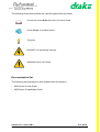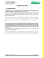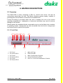
1
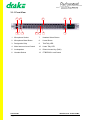
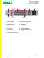
EASi-COM II
User Guide
ACKNOWLEDGEMENTS
It is the policy of Drake Electronics Limited (hereafter referred to as Drake) to
continually improve the products and Drake reserves the right to modify product
specifications and characteristics without notice, at any time.
Every endeavour has been made to ensure that information, details and descriptions
set out in this literature are correct at the time of going to press. However Drake is
unable to guarantee that no changes have subsequently taken place to the
specification or characteristics of, or relating to any Drake product, after the publication
of this literature. Drake shall not be liable for any loss or damage whatsoever arising
from the use of any information, errors or omissions in this guide or any use of the
product.
E. & O.E. Correct at Time of Publication
Neither the whole, nor any part of the information contained herein, nor in the products
described in this guide, may be adapted or reproduced in any material form except with
the prior written approval of Drake.
MS-DOS and Windows 95/98 are registered trademarks of Microsoft Corporation.
Telos is a trademark of TLS Corporation.
Ethernet is a registered trademark of Xerox Corporation.
All correspondence relating to products or guides should be addressed to:
Technical Support
Drake Electronics Limited
The Hydeway
Welwyn Garden City
Hertfordshire
United Kingdom
AL7 3UQ
Tel:- +44 (0)1727 871200
Fax:- +44 (0)1707 371266
E-Mail:- [email protected]
Website:- http://www.drake-uk.com
© 2000 All rights reserved.
4000 Series II - EASi-COM II
STA0309 - Issue 2.0
User Guide
Page i of x
DANGER
Electrical shock can cause severe personal injury or death. All
major units of this equipment are powered by mains voltage.
Unless specifically advised otherwise, DISCONNECT mains
supply before carrying out any maintenance or repair tasks.
European Union Declaration of Conformity
Drake declares that the following equipment has been manufactured in conformity with
the following standards:
BS EN 50081-1: 1992
Electromagnetic compatibility. Generic emission standard.
Residential, commercial and light industry.
BS EN 50082-1: 1998
Electromagnetic compatibility. Generic immunity standard.
Residential, commercial and light industry.
BS EN 60950: 1992
Safety of information technology equipment.
And thereby complies with the requirement of Electromagnetic Compatibility Directive
89/336/EEC and Low Voltage Directive 73/23/EEC as amended by 93/68/EEC.
User Guide
Page ii of x
4000 Series II - EASi-COM II
STA0309 - Issue 2.0
GLOSSARY OF TERMS
ADC
An Analogue to Digital Converter samples the voltage level of an
electrical input and assigns a digital value to it (a series of 1s and
0s).
ADM
Assignment, Diagnostics and Monitoring.
The CMAPSi package comprises two elements - an offline section
for configuring a Drake matrix and an online section for real time
monitoring and making 'on the fly' changes. ADM is the online section of the package.
BNC
Standard co-axial video connector.
A type of connector used with coaxial cables such as the RG-58 A/
U cable used with the 10Base-2 Ethernet system. The basic BNC
connector is a male type mounted at each end of a cable. This connector has a centre pin connected to the centre cable conductor
and a metal tube connected to the outer cable shield. A rotating ring
outside the tube locks the cable to any female connector.
CODEC
A Coder/Decoder is a device that encodes or decodes a signal. For
example, telephone companies use CODECs to convert binary signals transmitted on their digital networks to analogue signals converted on their analogue networks.
CMAPSi
Configuration and Master Assignment Programming System integrated is software produced by Drake Electronics, used for configuring, controlling and monitoring their 3000, 4000 and 4000 series II
range of matrices.
Conference
A facility (configured by CMAPSi), similar to older Party Line systems.
CSU
The Central Switching Unit is the central element of the Drake talkback system (responsible for the actual routing of audio), the CSU
is normally a 19 inch rack mounting unit. The CSU is sometimes
also referred to as the 'matrix'.
DAC
A Digital to Analogue Converter generates an output voltage proportional to the value entered on its digital inputs (as a series of 1s
and 0s).
DAK
Direct Access Key is a Drake term used to indicate a push key on a
control panel which, when pressed, will generate an audio route (or
routes), hence providing 'direct access' to a destination.
dB
The decibel (abbreviated as dB, and also as db and DB) is a common unit of measurement for the relative loudness of a sound or, in
electronics, for the relative difference between two power levels. A
decibel is one-tenth of a “Bel”, a seldom-used unit named after
Alexander Graham Bell, inventor of the telephone. In sound, the difference between two sound levels is ten times the common logarithm of the ratio of their power levels.
4000 Series II - EASi-COM II
STA0309 - Issue 2.0
User Guide
Page iii of x
Destination port
The port used as the target port when assigning a route.
EPROM
Erasable Programmable Read-Only Memory is a special type of
memory that retains its contents until it is exposed to ultraviolet
light. The ultraviolet light clears its contents, making it possible to
reprogram the memory. To write to and erase an EPROM, you need
a special device called a PROM programmer or PROM burner.
An EPROM differs from a PROM in that a PROM can be written to
only once and cannot be erased. EPROMs are used widely in personal computers because they enable the manufacturer to change
the contents of the PROM before the computer is actually shipped.
This means that bugs can be removed and new versions installed
shortly before delivery.
GPI
A General Purpose Interface is a series of digital control lines, comprising both inputs and outputs which allows the connection of third
party pieces of equipment to a Drake CSU (q.v.). By programming
the operation of these control lines through the CMAPSi (q.v.) package, a third party piece of equipment can be made to interact with
the CSU.
GPSF
A General Purpose Special Function is a set of CSU commands
which can be associated with a GPI (q.v.) input, such that the commands are executed when the logic level of the specified input
changes to the desired state. For example, a GPSF could be used
to generate an audio route between two ports when one of the GPI
input pins became logic 'high'.
Howlround
Distorted audio - due to feedback of original signal in close proximity. An audio resonance which is generated by the audio from an
output being fed back into its input. Feedback is characterised by a
high pitch 'squeal' and can be observed when a microphone is
placed in close proximity to a loudspeaker when there is an audio
route between the microphone and the loudspeaker.
I/O
Input/Output
I/P
Input
IFB
Interruptable Foldback provides a caller with the ability to talk over a
normal audio feed (source) to an operator (destination). An IFB
defines matrix connections between source and destination ports
while allowing IFB callers to interrupt a source and talk to a destination.
Local
Programming
Modifying the DAK assignments via the Intelligent Control Panel
SOFT Mode
User Guide
Page iv of x
4000 Series II - EASi-COM II
STA0309 - Issue 2.0
LCD
A Liquid Crystal Display is a type of display used in digital watches
and many portable computers. LCD displays utilize two sheets of
polarizing material with a liquid crystal solution between them. An
electric current passed through the liquid causes the crystals to
align so that light cannot pass through them. Each crystal, therefore, is like a shutter, either allowing light to pass through or blocking the light.
LED
A Light Emitting Diode is an electronic device that lights up when
electricity is passed through it.
Listen Route
An audio route to the Control Panel from a source. The audio is normally heard on the Control Panel's Loudspeaker or Headset.
LS
The Loudspeaker is a device that converts electrical signals into
sound waves.
MB
A MegaByte is a term used for data size: 1MB = 1,024 bytes
MHz
Megahertz is a term used to express the speed of a waveform. 1
MHz = 1 million Hertz (q.v.), or cycles per second. The speed of
microprocessors, called the clock speed, is measured in megahertz.
N/C
A Normally Closed contact is a contact that is always closed until
operated.
N/O
A Normally Open contact is a contact that is always open until operated.
NID
A Non Intrusive Download is a means of sending new configuration
information from a personal computer to a Drake CSU while causing minimum interruption to the live operation of the system.
NVRAM
Non-Volatile Random Access Memory is a type of memory that
retains its contents when power is turned off. One type of NVRAM is
SRAM that is made non-volatile by connecting it to a constant
power source such as a battery. Another type of NVRAM uses EEPROM chips to save its contents when power is turned off. In this
case, NVRAM is composed of a combination of SRAM and EEPROM chips.
O/P
Output
PCB
A Printed Circuit Board is a thin plate on which silicon chips and
other electronic components are placed.
Pot.
A Potentiometer is a variable resistance device used to control
sound levels.
PSU
A Power Supply Unit is a unit which converts an electrical supply to
one suitable for driving a given piece of equipment. Typically, a
power supply unit will convert from alternating current to direct current and will step down the supply voltage.
4000 Series II - EASi-COM II
STA0309 - Issue 2.0
User Guide
Page v of x
RAM
Random Access Memory is a type of computer memory that can be
accessed randomly; that is, any byte of memory can be accessed
without touching the preceding bytes.
RCU
Rear Connector Unit. Larger Drake CSUs are configurable by the
fitting of extra boards to a passive backplane. Some of these boards
require connections to the outside world. These connections are
typically provided on a second (smaller) board which mates with the
main board at its rear. These smaller connector units are referred to
as 'Rear Connector Units'.
RMS
The Root Mean Squared value of a set of figures is the square root
of mean average of the square of each value.
RU
A standard Rack Unit is a measurement used in the broadcast
industry to indicate the amount of cabinet (or rack) space a piece of
equipment will require. 1 RU is 19 inches wide by 1.75 inches high
(or 482.6 mm by 44.45 mm).
Side tone
Side tone is the audio, heard in the Headset earpiece, which is generated by the headset microphone. This allows the operators to
hear themselves when using headsets.
Source port
The port used as the origin when assigning a route.
TA
A Terminal Adaptor is a device that connects a computer to an
external digital communications line, such as an ISDN line. A terminal adapter is a bit like a modem, but whereas a modem needs to
convert between analogue and digital signals, a terminal adapter
only needs to pass along digital signals.
Talkback
A broadcast term referring to the intercom system.
Talk Route
An audio route from the Control Panel to another destination. The
audio is normally generated from the Control Panel's main microphone or Headset microphone.
TBU
Telephone Balance Unit.
VOX
A Voice Operated Crosspoint is a a switch which operates when the
level of a signal passing through it rises above a certain threshold
level. This threshold is normally adjustable either electronically or
mechanically, depending on the type of switch.
XLR
Audio industry standard connector.
User Guide
Page vi of x
4000 Series II - EASi-COM II
STA0309 - Issue 2.0
The following terms and symbols are used throughout this document:
Consult the named Drake document for further details.
Contact Drake for suitable options.
Tips given.
DANGER: Life-threatening warnings
WARNINGS and CAUTIONS
Documentation Set
The following documentation is also supplied with this product:
• 4000 Series II User Guide
• 4000 Series II Installation Guide
4000 Series II - EASi-COM II
STA0309 - Issue 2.0
User Guide
Page vii of x
User Guide
Page viii of x
4000 Series II - EASi-COM II
STA0309 - Issue 2.0
TABLE OF CONTENTS
1. INTRODUCTION .................................................................................................. 11
1.1 System Overview ........................................................................................... 11
2. MATRIX DESCRIPTION ...................................................................................... 13
2.1 Overview ........................................................................................................ 13
2.1.1 Front View ........................................................................................................... 13
2.2 Controls and Indicators .................................................................................. 14
2.2.1 Supply 1 Fuse ..................................................................................................... 14
2.2.2 Supply 1 Fuse Indicator ...................................................................................... 14
2.2.3 Supply 2 Fuse ..................................................................................................... 14
2.2.4 Supply 2 Fuse Indicator ...................................................................................... 14
2.2.5 Supply 3 Fuse ..................................................................................................... 14
2.2.6 Supply 3 Fuse Indicator ...................................................................................... 14
2.2.7 AC Supply Fuse .................................................................................................. 14
2.2.8 Power On Indicator ............................................................................................. 15
2.2.9 Matrix Configuration Switches ............................................................................ 15
2.2.10 Control Panel Active Indicators ......................................................................... 15
2.2.11 Input, Output and Balance Adjustments ............................................................ 15
3. THE 1310 CONTROL PANEL (1RU) .................................................................. 17
3.1 Overview ........................................................................................................ 17
3.1.1 Front View ........................................................................................................... 18
3.2 Controls and Indicators .................................................................................. 19
3.2.1 Microphone Socket ............................................................................................. 19
3.2.2 Microphone Mute Button ..................................................................................... 19
3.2.3 Designation Strip ................................................................................................. 19
3.2.4 Main Intercom Level Control ............................................................................... 19
3.2.5 Loudspeaker ....................................................................................................... 19
3.2.6 Headset Socket ................................................................................................... 19
3.2.7 Headset Select Button ........................................................................................ 20
3.2.8 Listen Button ....................................................................................................... 20
3.2.9 Talk Tally LED ..................................................................................................... 20
3.2.10 Listen Tally LED ................................................................................................ 20
3.2.11 Direct Access Key (DAK) .................................................................................. 20
3.2.12 PTB/PROG Level Control ................................................................................. 21
4. THE 1320 CONTROL PANEL (2RU) .................................................................. 23
4.1 Overview ........................................................................................................ 23
4.1.1 Front View ........................................................................................................... 24
4.2 Controls and Indicators .................................................................................. 25
4000 Series II - EASi-COM II
STA0309 - Issue 2.0
User Guide
Page ix of x
4.2.1 Microphone Socket ............................................................................................. 25
4.2.2 Dial Button .......................................................................................................... 25
4.2.3 Beltpack Call Button ............................................................................................ 26
4.2.4 Microphone Mute Button ..................................................................................... 26
4.2.5 Designation Strip ................................................................................................. 26
4.2.6 Talk Tally LED ..................................................................................................... 26
4.2.7 Listen Tally LED .................................................................................................. 26
4.2.8 Direct Access Key (DAK) .................................................................................... 26
4.2.9 Auxiliary 2 Level Control ..................................................................................... 27
4.2.10 Main Intercom Level Control ............................................................................. 27
4.2.11 DTMF Dial Keypad ............................................................................................ 27
4.2.12 Loudspeaker ..................................................................................................... 27
4.2.13 Headset Socket ................................................................................................. 27
4.2.14 Headset Select Button ...................................................................................... 28
4.2.15 Listen Button ..................................................................................................... 28
4.2.16 Auxiliary 1 Level Control ................................................................................... 28
4.2.17 PTB/PROG Level Control ................................................................................ 28
User Guide
Page x of x
4000 Series II - EASi-COM II
STA0309 - Issue 2.0
1. INTRODUCTION
1.1 System Overview
The EASi-COM II is a Communications System using a central switching matrix for
routing calls between outstations connected in a star format.
The central switching matrix uses a controller for control and configuration purposes
and an analogue switching element allowing multiple routes to be made
simultaneously. Analogue audio, DCC inputs and outputs, are also provided as part of
the EASi-COM II system.
A range of Control Panels is available providing a suitable user interface for making
and receiving calls over the system. These panels feature push buttons configured to
operate specific routes or activate control functions. The key actions are sent as digital
data using a serial link to the central matrix for interpretation by the controller and
information is returned to the control panel by the same method. Audio and data is
connected via standard multi-core twisted pair wiring.
A call is initiated on a control panel by pressing one of the Direct Access Keys (DAK).
This activates crosspoints, located in the Matrix, which make the audio route (or routes)
to the desired destination(s). Routing can be one-way (e.g. talk only) or two-way (talk
and listen simultaneously) and several callers can speak to the same destination at the
same time.
Destinations and sources may be beltpacks, IFBs, 2-wire or 4-wire circuits, or other
panels, individually or grouped.
A camera conference facility is also available, configured via the Matrix DIL switches,
which allows people to communicate in a conference mode. This is similar in operation
to the Conference Ring (Party Line) facilities available in older, more conventional
systems.
4000 Series II - EASi-COM II
STA0309 - Issue 2.0
User Guide
Page 11 of 30
User Guide
Page 12 of 30
4000 Series II - EASi-COM II
STA0309 - Issue 2.0
2. MATRIX DESCRIPTION
2.1 Overview
The EASi-COM II matrix comprises a 2RU by 19-inch rack mount unit with all
connections made from the rear. The Matrix contains a power supply, capable of
powering the Control Panels, connected via a standard IEC.
Forced air-cooling is provided within the unit to maintain the unit at the correct
operating temperatures. Inadequate or obstructed ventilation may result in serious
damage to the system.
Switch options are available behind a removable cover to set the Matrix into a number
of operating modes. Adjustments are also accessible from the front to change input
and output levels in parts of the system.
2.1.1 Front View
1
2
3
4
5
9
1
2
3
4
5
6
DC Fuse 1
DC Power LED 1
DC Fuse 2
DC Power LED 2
DC Fuse 3
DC Power LED 3
4000 Series II - EASi-COM II
STA0309 - Issue 2.0
6
7
8
10
11
7
8
9
10
11
Mains AC Fuse
Power ON LED
Matrix Configuration Switches
Control Panel Activity LEDs
Port 5 to 14 I/O Level and Balance Controls
User Guide
Page 13 of 30
2.2 Controls and Indicators
2.2.1 Supply 1 Fuse
This is a 6.3A Anti-surge fuse.
Contact Drake for suitable replacement part.
2.2.2 Supply 1 Fuse Indicator
This indicates if the supply fuse has blown. The LED is on if the power is on and the
fuse is OK.
2.2.3 Supply 2 Fuse
This is a 6.3A Anti-surge fuse.
Contact Drake for suitable replacement part.
2.2.4 Supply 2 Fuse Indicator
This indicates if the supply fuse has blown. The LED is on if the power is on and the
fuse is OK.
2.2.5 Supply 3 Fuse
This is a 2A Anti-surge fuse.
Contact Drake for suitable replacement part.
2.2.6 Supply 3 Fuse Indicator
This indicates if the supply fuse has blown. The LED is on if the power is on and the
fuse is OK.
2.2.7 AC Supply Fuse
This is a 6.3A Anti-surge fuse for 120 Volts operation or 3.15A Anti surge fuse for 240
Volts operation.
Contact Drake for suitable replacement part.
User Guide
Page 14 of 30
4000 Series II - EASi-COM II
STA0309 - Issue 2.0
2.2.8 Power On Indicator
This indicates if the AC supply fuse has blown. The LED is on if the power is on and
the fuse is OK.
2.2.9 Matrix Configuration Switches
These are used to configure the matrix operation.
Consult the Drake Installation Guide for further details.
2.2.10 Control Panel Active Indicators
This indicates if a control panel is connected to a port and is communicating to the
matrix.
2.2.11 Input, Output and Balance Adjustments
The input and output levels for ports 7 to 14 can be adjusted by +/- 10 dB. Turn the
adjusters anticlockwise to increase the gain and clockwise to reduce the gain
If ports 5 to 10 are 2-wire ports, either beltpacks or cameras, then the 2-wire sidetone,
or balance, can be reduced.
Consult the Drake Installation Guide for further details.
4000 Series II - EASi-COM II
STA0309 - Issue 2.0
User Guide
Page 15 of 30
User Guide
Page 16 of 30
4000 Series II - EASi-COM II
STA0309 - Issue 2.0
3. THE 1310 CONTROL PANEL (1RU)
3.1 Overview
The EASi-COM 1310 Control Panel is a 1RU by 19-inch rack mounting unit. The Matrix
powers the Control Panel for distances up to 150m but for greater distances the panel
can be powered from an external supply. The panel can then be located at distances
up to 500m, depending on cable type.
The Control Panel features sixteen pushbutton Direct Access Keys (DAK) which allow
communication with all ports in the system. The DAKs can be programmed to have
separate Talk and Listen actions or a combined Talk + Listen action. All programming
is lost when power is removed, but jumpers on the Control Panel circuit board can set
the power on defaults.
The 1310 - 16 Key Control Panel Level Control Panel has the following features:
• 16 pushbutton Direct Access Keys
• Programmable pushbuttons for talk, listen, and talk + listen functions
• Loudspeaker output jack
• Separate audio inputs and level controls for Main Intercom and Production Talkback/Programme
• DC powered from the Matrix or an external power supply
• Audio and control interface options
• Full signalisation of send and receive routes
• Plug-in microphone or headset operation
• Microphone gain, headset gain and side-tone adjustment at rear
• Headset connector with pushbutton select
• Designation strip for key identification
4000 Series II - EASi-COM II
STA0309 - Issue 2.0
User Guide
Page 17 of 30
3.1.1 Front View
1
6
2
7
8
9
3
4
10
11
12
1
Microphone Socket
7
Headset Select Button
2
Microphone Mute Button
8
Listen Button
3
Designation Strip
9
Talk Tally LED
4
Main Intercom Level Control
10
Listen Tally LED
5
Loudspeaker
11
Direct Access Key (DAK)
6
Headset Socket
12
PTB/PROG LevelControl
User Guide
Page 18 of 30
5
4000 Series II - EASi-COM II
STA0309 - Issue 2.0
3.2 Controls and Indicators
3.2.1 Microphone Socket
Insert the optional microphone into this socket. The detachable microphone is
connected via a 3-pin screw locking DIN connector.
Contact Drake for suitable detachable microphone options.
3.2.2 Microphone Mute Button
Press the Microphone Mute Button to mute the microphone. The red LED is illuminated
if the microphone is muted.
3.2.3 Designation Strip
Insert a Designation Strip to indicate the area of communication for each of the direct
access keys.
3.2.4 Main Intercom Level Control
Turn the main volume control clockwise to increase intercom volume, anticlockwise to
decrease.
3.2.5 Loudspeaker
Audio is output from the loudspeaker unless the headset Select Button (see item 3.2.7)
is on or an external loudspeaker is connected via the External Loudspeaker jack
socket.
Contact Drake for suitable external loudspeaker options.
Consult the Drake Installation Guide for further details on connecting
external loudspeakers.
3.2.6 Headset Socket
The 5 pin DIN Headset socket is used to connect an optional headset for use when the
main microphone and loudspeaker are not required.
4000 Series II - EASi-COM II
STA0309 - Issue 2.0
User Guide
Page 19 of 30
(Headsets should be used in areas where a number of control panels are used in close
proximity; this should avoid any possibility of howlround occurring).
Contact Drake for suitable headset options.
3.2.7 Headset Select Button
The Headset Button is used to select headset operation. When it is switched on, the
LED is on, the headset microphone is active and the main microphone and
loudspeaker are muted.
3.2.8 Listen Button
The Listen Button allows listen routes to be switched on independently of talk routes.
This mode will only operate on a DAK if it has been programmed for separate Talk and
Listen actions (see item 3.2.11).
Whilst the Listen Button is being pressed, the DAK's can be pressed to turn the Listen
Route on or off.
3.2.9 Talk Tally LED
This Red LED indicates that audio is being sent by the control panel to the destination
associated with the DAK.
3.2.10 Listen Tally LED
This Green LED indicates that audio is being received by the control panel from the
source associated with the DAK.
3.2.11 Direct Access Key (DAK)
The Control Panel has sixteen Direct Access Key buttons. These buttons are used to
make Listen and/or Talk routes to and from the Control Panel.
The buttons operate with a Latch/Non-latch mode of operation. A quick press of the
button latches it on and any other press will switch the button latch off. A prolonged
press will keep the button switched until it is released.
3.2.11.1 Programming
The Direct Access Keys can be programmed with a combined Talk-Listen action, i.e. a
2-way audio route, or as separate Talk and Listen actions. The mode is selected by
simultaneously pressing and holding the Headset and Microphone Mute buttons.
While the Headset and Microphone Mute buttons are being pressed, the tally LED's for
the DAK's will flash if programmed as combined Talk/Listen or will be off if set for
separate Talk and Listen actions.
User Guide
Page 20 of 30
4000 Series II - EASi-COM II
STA0309 - Issue 2.0
Pressing any of the DAK's while the Headset and Microphone Mute buttons are also
pressed will change the mode of operation for that DAK between combined Talk/Listen
or separate Talk and Listen.
When a DAK is in the separate Talk and Listen mode, the Listen action can be selected
separately using the Listen Button (See item 3.2.8).
3.2.12 PTB/PROG Level Control
Turn the auxiliary volume control clockwise to increase the auxiliary channel volume,
or anticlockwise to decrease. The auxiliary channel is usually set-up as production
Talkback or Program Sound.
Consult the Drake Installation Guide for further details.
4000 Series II - EASi-COM II
STA0309 - Issue 2.0
User Guide
Page 21 of 30
User Guide
Page 22 of 30
4000 Series II - EASi-COM II
STA0309 - Issue 2.0
4. THE 1320 CONTROL PANEL (2RU)
4.1 Overview
The EASi-COM 1320 Control Panel is a 2RU by 19-inch rack mounting unit. The Matrix
powers the Control Panel for distances up to 150m but for greater distances the panel
can be powered from an external supply. The panel can then be located at distances
up to 500m, depending on cable type.
The Control Panel features sixteen pushbutton Direct Access Keys (DAK) which allow
communication with all ports in the system. The DAKs can be programmed to have
separate Talk and Listen actions or a combined Talk + Listen action. All programming
is lost when power is removed, but jumpers on the Control Panel circuit board can set
the power on defaults.
This Control Panel is equipped with a DTMF keypad to dial up across telephone lines
when an appropriate Telephone Hybrid is connected to the Matrix.
The 1320 - 16 Key Control Panel Level Control Panel has the following features:
• 16 pushbutton Direct Access Keys
• Programmable pushbuttons for talk, listen, and talk + listen functions
• DTMF keypad for telephone dialling operation
• Loudspeaker output jack
• Separate audio inputs and level controls for Main Intercom, Auxiliary 1 and 2, and
production Talkback/Programme
• VOX detection on the Auxiliary 1 and 2 inputs
• DC powered from the Matrix or an external power supply
• Audio and control interface options
• Full signalisation of send and receive routes
• Plug-in microphone or headset operation
• Microphone gain, headset gain and side-tone adjustment at rear
• Headset connector with pushbutton select
• Designation strip for key identification
4000 Series II - EASi-COM II
STA0309 - Issue 2.0
User Guide
Page 23 of 30
4.1.1 Front View
1
13
2
3
4
5
6
7
8
14 15
9
10
16
17
11
1
Microphone Socket
10
Main Intercom Level Control
2
Dial Button
11
DTMF Dial Keypad
3
Beltpack Call Button
12
Loudspeaker
4
Microphone Mute Button
13
Headset Socket
5
Designation Strip
14
Listen Button
6
Talk Tally LED
15
Headset Select Button
7
Listen Tally LED
16
Auxiliary 1 Level Control (IFB2)
8
Direct Access Key (DAK)
17
PTB/PROG Level Control
9
Auxiliary 2 Level Control (IFB2)
User Guide
Page 24 of 30
12
4000 Series II - EASi-COM II
STA0309 - Issue 2.0
4.2 Controls and Indicators
4.2.1 Microphone Socket
Insert the optional microphone into this socket. The detachable microphone is
connected via a 3-pin screw locking DIN connector.
Contact Drake for suitable detachable microphone options.
4.2.2 Dial Button
Press the dial button to use the DTMF keypad.
4.2.2.1 DTMF Tone to RT Equipment.
Operating the Dial Button allows the panel to send DTMF tone to RT equipment, if
connected.
Contact Drake for suitable RT equipment options.
Consult the Drake Installation Guide for further details on connecting
RT equipment.
4.2.2.2 Dialling Telephone Lines
Operating the Dial Button allows the panel to dial to a telephone line if a telephone
hybrid is connected to the system. The red LED is illuminated if DTMF is enabled and
this will only operate if a telephone hybrid is connected and switched on. In addition,
this button grabs the telephone line and opens a Talk and Listen route.
Contact Drake for suitable Telephone Hybrid options.
Consult the Drake Installation Guide for further details on connecting
telephone hybrids.
4000 Series II - EASi-COM II
STA0309 - Issue 2.0
User Guide
Page 25 of 30
4.2.3 Beltpack Call Button
Press the beltpack call button to initiate a call and illuminate the call LED on the
beltpacks if connected. The red LED is illuminated while the button is being pressed.
This is a non-latch button.
Contact Drake for more details on Beltpacks and other related products.
4.2.4 Microphone Mute Button
Press the Microphone Mute Button to mute the microphone. The red LED is illuminated
if the microphone is muted.
4.2.5 Designation Strip
Insert a Designation Strip to indicate the area of communication for each of the direct
access keys.
4.2.6 Talk Tally LED
This Red LED indicates that audio is being sent by the control panel to the destination
associated with the DAK.
4.2.7 Listen Tally LED
This Green LED indicates that audio is being received by the control panel from the
source associated with the DAK.
4.2.8 Direct Access Key (DAK)
The Control Panel has sixteen Direct Access Key buttons. These buttons are used to
make Listen and/or Talk routes to and from the Control Panel.
The buttons operate with a Latch/Non-latch mode of operation. A quick press of the
button latches it on and any other press will switch the button latch off. A prolonged
press will keep the button switched until it is released.
4.2.8.1 Programming
The Direct Access Keys can be programmed with a combined Talk-Listen action, i.e. a
2-way audio route, or as separate Talk and Listen actions. The mode is selected by
simultaneously pressing and holding the Headset and Microphone Mute buttons.
While the Headset and Microphone Mute buttons are being pressed, the tally LED's for
the DAK's will flash if programmed as combined Talk/Listen or will be off if set for
separate Talk and Listen actions.
Pressing any of the DAK's while the Headset and Microphone Mute buttons are also
pressed will change the mode of operation for that DAK between combined Talk/Listen
or separate Talk and Listen.
User Guide
Page 26 of 30
4000 Series II - EASi-COM II
STA0309 - Issue 2.0
When a DAK is in the separate Talk and Listen mode, the Listen action can be selected
separately using the Listen Button (See item 4.2.15).
4.2.9 Auxiliary 2 Level Control
Turn the main volume control clockwise to increase intercom volume, anticlockwise to
decrease.
Consult the Drake Installation Guide for further details.
4.2.10 Main Intercom Level Control
Turn the auxiliary volume control clockwise to increase the auxiliary channel volume,
or anticlockwise to decrease.
4.2.11 DTMF Dial Keypad
Use the keypad for dialling to a telephone line if connected, or generating a DTMF tone
for transmission by radio talkback.
4.2.12 Loudspeaker
Audio is output from the loudspeaker unless the headset Select Button (see item
4.2.14) is on, or an external loudspeaker is connected via the External Loudspeaker
jack socket.
Contact Drake for suitable external loudspeaker options.
Consult the Drake Installation Guide for further details on connecting
external loudspeakers.
4.2.13 Headset Socket
The 5 pin DIN Headset Socket is used to connect an optional headset for use when the
main microphone and loudspeaker are not required.
(Headsets should be used in areas where a number of control panels are used in close
proximity, this should avoid any possibility of howlround occurring).
Contact Drake for suitable Headset options.
4000 Series II - EASi-COM II
STA0309 - Issue 2.0
User Guide
Page 27 of 30
4.2.14 Headset Select Button
The Headset Button is used to select headset operation. When it is switched on, the
LED is on, the headset microphone is active and the main microphone and
loudspeaker are muted.
4.2.15 Listen Button
The Listen Button allows listen routes to be switched on independently of talk routes.
This mode will only operate on a DAK if it has been programmed for separate Talk and
Listen actions (see item 4.2.8.1).
While the Listen Button is being pressed, the DAK's can be pressed to turn the Listen
Route on or off.
4.2.16 Auxiliary 1 Level Control
Turn the auxiliary volume control clockwise to increase the auxiliary channel volume,
or anticlockwise to decrease.
Consult the Drake Installation Guide for further details.
4.2.17 PTB/PROG Level Control
Turn the Prog/PTB volume control clockwise to increase the auxiliary channel volume,
or anticlockwise to decrease.
Consult the Drake Installation Guide for further details.
User Guide
Page 28 of 30
4000 Series II - EASi-COM II
STA0309 - Issue 2.0
INDEX
Numerics
I
2-wire ...................................................... 11
2-wire ports ............................................... 15
2-wire sidetone .......................................... 15
4-wire circuits ............................................ 11
5 pin DIN .................................................. 27
Intercom Level Control ................................. 27
intercom volume ......................................... 27
A
audio ....................................................... 23
audio input .......................................... 17, 23
Auxiliary 1 Level Control ............................... 28
Auxiliary 2 Level Control ............................... 27
auxiliary channel ........................................ 21
auxiliary channel volume .............................. 27
auxiliary volume ................................... 21, 28
B
beltpack ....................................... 11, 15, 26
Beltpack Call Button .................................... 26
C
camera ..................................................... 15
camera conference facility ............................ 11
channel volume .......................................... 28
conference mode ........................................ 11
Conference Ring ........................................ 11
Control Panel ............................................ 23
crosspoints ............................................... 11
D
L
level control ......................................... 17, 23
Listen Button ........................... 20, 21, 27, 28
Listen Route .............................................. 28
Listen Tally LED ................................... 20, 26
loudspeaker ...................... 19, 20, 23, 27, 28
Loudspeaker output jack .............................. 17
M
Main Intercom ...................................... 17, 23
Main Intercom Level Control .......................... 19
microphone 17, 19, 20, 21, 23, 25, 26, 27, 28
Microphone Mute ............................ 20, 21, 26
Microphone Mute Button ........................ 19, 26
Microphone Socket ............................... 19, 25
Mute Button ............................................... 19
P
Production Talkback .................................... 17
Prog/PTB volume ....................................... 28
R
rack mounting unit ...................................... 23
radio talkback ............................................ 27
RT equipment ............................................ 25
designation strip ............................. 19, 23, 26
dial .......................................................... 25
Dial Button ................................................ 25
DIN connector ...................................... 19, 25
Direct Access Key ..11, 17, 19, 20, 21, 23, 26,
S
27, ......................................................... 28
DTMF ...................................................... 25
DTMF Dial Keypad ..................................... 27
DTMF keypad ...................................... 23, 25
DTMF tone .......................................... 25, 27
T
E
V
external loudspeaker .............................
external power supply ............................
external supply .....................................
19, 27
17, 23
17, 23
send and receive routes ............................... 17
side-tone adjustment ............................. 17, 23
switching matrix ......................................... 11
Talk Tally LED ..................................... 20,
telephone hybrid ................................... 23,
telephone line ...................................... 23,
26
25
25
volume control ..................................... 19, 27
VOX ........................................................ 23
H
headset .................17, 19, 20, 21, 23, 26, 27
headset button ........................................... 28
headset gain ............................................. 23
headset select button .................................. 20
headset socket ..................................... 19, 27
howlround ........................................... 20, 27
4000 Series II - EASi-COM II
STA0309 - Issue 2.0
User Guide
Page 29 of 30
User Guide
Page 30 of 30
4000 Series II - EASi-COM II
STA0309 - Issue 2.0