1
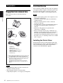
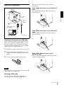
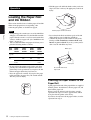
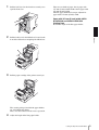
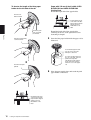
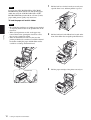
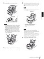
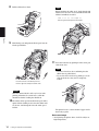
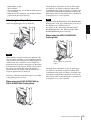
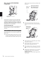
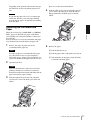
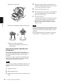
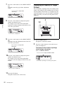
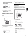
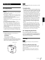
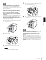
2-318-816-35(1)
Digital Photo Printer
Operating Instructions
UP-DR150
© 2004 Sony Corporation
Owner's Record
The model and serial numbers are located at the rear.
Record these number in the space provided below.
Refer to these numbers whenever you call upon your
Sony dealer regarding this product.
Model No. ____________________
Serial No. ____________________
WARNING
To reduce the risk of fire or electric shock, do
not expose this apparatus to rain or moisture.
To avoid electrical shock, do not open the
cabinet. Refer servicing to qualified personnel
only.
THIS APPARATUS MUST BE EARTHED.
To disconnect the main power, unplug the AC
IN connector.
For the customers in the U.S.A.
This equipment has been tested and found to comply
with the limits for a Class A digital device, pursuant to
Part 15 of the FCC Rules. These limits are designed to
provide reasonable protection against harmful
interference when the equipment is operated in a
commercial environment. This equipment generates,
uses, and can radiate radio frequency energy and, if not
installed and used in accordance with the instruction
manual, may cause harmful interference to radio
communications. Operation of this equipment in a
residential area is likely to cause harmful interference in
which case the user will be required to correct the
interference at his own expense.
You are cautioned that any changes or modifications not
expressly approved in this manual could void your
authority to operate this equipment.
All interface cables used to connect peripherals must be
shielded in order to comply with the limits for a digital
device pursuant to Subpart B of Part 15 of FCC Rules.
2
Warning on power connection
Use a proper power cord for your local power supply.
1. Use the approved Power Cord (3-core mains lead) /
Appliance Connector / Plug with earthing-contacts
that conforms to the safety regulations of each
country if applicable.
2. Use the Power Cord (3-core mains lead) / Appliance
Connector /Plug conforming to the proper ratings
(Voltage, Ampere).
If you have questions on the use of the above Power
Cord/Appliance Connector/Plug, please consult a
qualified service personnel.
Table of Contents
Introduction
Features .................................................................. 4
Basic Application Example ................................ 4
Location and Function of Parts and Controls .... 4
Preparation
Supplied Accessories ............................................. 6
Connections ............................................................ 6
Installing the Printer Driver ................................ 6
USB Port Connection ......................................... 7
Operation
Loading the Paper Roll and Ink Ribbon ............. 8
Attaching the Paper Holders to the Paper Roll ... 8
Loading the Paper Roll and Ink Ribbon ........... 11
Attaching the Paper Tray .................................. 15
If the Ink Ribbon Breaks during Use ............... 16
Removing the Ink Ribbon and Paper ............... 17
Printing from the Computer ............................... 19
Menu Operations ................................................. 20
Preparation for Menu Operation ...................... 20
Adjusting the Gray Balance ............................. 21
Displaying the Quantity of Pages Printed ........ 22
Displaying the Firmware Version of the Printer ...
23
Adjusting the Position of the Printout Image ... 23
Miscellaneous
Precautions ........................................................... 25
Safety ................................................................ 25
Installation ........................................................ 25
On Transporting the Printer .............................. 25
Cleaning ........................................................... 25
Ink Ribbon and Paper ......................................... 29
Specifications ........................................................ 29
List of Messages ................................................... 30
Troubleshooting ................................................... 31
Index ..................................................................... 33
3
Introduction
Introduction
Features
The UP-DR150 Digital Photo Printer is a dye
sublimation thermal transfer printer providing high
quality, high resolution (334 dpi), and high speed
printing of computer image data on four sizes of paper
in full color (256 gradations process and 16.7 million
colors).
Location and Function
of Parts and Controls
For more details, see the reference pages numbers
enclosed in parentheses.
Front panel
Basic Application Example
Computer: provides
image data for printing
and printer control
signals
Rear panel
UP-DR150 Digital Photo Printer
A ALARM indicator (30)
Lights in red when the system is initialized, or when
an error occurs.
4
Features / Location and Function of Parts and Controls
B LCD (liquid crystal display) (19, 22, 30)
Displays the number of pages printed, or the
amount of ink ribbon remaining. Messages are
displayed when an error or warning condition
occurs.
H Front panel
Buttons to be used for menu operation are located
under this front panel.
Introduction
C Lock lever for the front door
Used to open the front door when loading or
replacing the ink ribbon and paper, or cleaning.
G Support
Pull out the support when using the 2UPC-R155/
R155H and 2UPC-R156/R156H Printing Pack.
Key panel section
When the front door opens
A EXEC Button (21)
Press this button to print the gray scale adjustment
pattern.
B MENU Button (22)
Press this button to carry out menu operations.
Pressing the MENU button changes the printer to
the off-line mode.
A Paper cartridge
The paper roll is placed here.
B Ribbon base
The ink ribbon is attached here.
C Lock lever for the ribbon base
Pull the lever so that you can pull up the ribbon
base.
D Filter
D Ventilation holes
A filter for the cooling fan to prevent the thermal
head from overheating is located.
E Paper Output Slot
Printed pages are output from the printer here.
F Paper tray (15)
The printouts are ejected onto this tray. Adjust the
length of the paper tray according to the printing
pack to be used.
A margin of about 20mm drops into this tray.
C Cursor Buttons (22)
Press these buttons to select the item to be
displayed on the LCD.
D CAL (calibration) button (21)
Press this button to adjust the gray balance.
E PRINT STOP button (20)
Pressing the PRINT STOP button for more than one
second during printing results in cancelling the
number of printings set and clearing the images
stored in the memory. The printer stops printing
when the page currently printing is completed and
ejected.
I - AC IN (Power Source) Connector (6)
Connect the supplied power cord here.
J !POWER switch (19)
Press this switch to turn the printer on or off.
K USB connector (7)
Connects to a computer equipped with the USB
interface (which conforms to USB 2.0), using a
USB cable (not supplied).
Location and Function of Parts and Controls
5
Preparation
Supplied Accessories
Make certain you have received the following
accessories:
Preparation
Paper Tray a) (1)
Paper holders b) (2)
AC power cord (1)
CD-ROM (1)
Ferrite core (1)
Operating Instructions (1)
Software License Agreement (1)
Warranty Card (1)
Service and Customer Support
Information (1)
a) Before attaching the paper tray, be sure to remove the
corrugated paper from the inside of the paper tray.
b) The paper holders are stored in the printer. Be sure to
remove the two paper holders from the inside of the
printer before turning the power on.
For details on how to remove them, see step 1 of
“Attaching the Paper Holders to the Paper Roll” on
page 8
Notes
• When taking the printer out of the carton box, be
careful not to hurt your back.
• The packaging materials are needed when
transporting the printer, so we suggest you keep them.
6
Supplied Accessories / Connections
Connections
After connecting a USB connecting cable (not supplied)
to the printer and the computer, connect the power cord.
For details about the printer connection, refer to the
manuals for the computer or other peripheral devices.
Notes
• Before connecting the printer to the computer, be sure
to install the printer driver.
• Follow the connection procedures described in the
computer manual.
• Make sure that the interface cable is connected
securely at both ends.
• The printer drive software provided with the printer is
not suitable for using the printer connected to a
network.
• Operation of the printer is not guaranteed for
connection to a USB hub.
• Before connecting the unit using a USB cable (not
supplied), attach a supplied ferrite core to the end of
the cable to be connected to the printer for noise
prevention. For detailed information on how to attach
the ferrite cores, see “Attaching a ferrite core to a USB
cable” on page 7.
Installing the Printer Driver
Install the printer driver provided with the printer. For
detailed instructions on how to install the printer driver,
refer to the Readme.txt file and the install manual
contained on the CD-ROM disc supplied.
illustrated, to prevent it from being accidentally
disonnected.
USB Port Connection
When a USB cable of about 5-mm in diameter is
used
Pass the USB cable under the upper cable stopper as
illustrated below.
UP-DR150
Preparation
to - AC IN
connector
AC power
cord
(supplied)
to
(USB) connector
USB connecting cable
(not supplied)
to wall outlet
When a USB cable of about 4-mm in diameter is
used
Pass the USB cable under the lower cable stopper as
illustrated below.
Computer
Attaching a ferrite core to a USB cable
Before connecting a USB cable (not supplied) to the
printer, you should attach a supplied ferrite core to its
cable for noise prevention. To conform to radiation
standards, attach the supplied ferrite core to the USB
cable of your device as described below.
1
Release two stoppers on the ferrite core to open it.
2
Slip the USB cable through the ferrite core and
position it at the base of the USB connector to the
printer.
3
Close the ferrite core until you hear a click.
When a USB cable of less than 4-mm in
diameter is used
Pass the USB cable between the lower and upper cable
stoppers as illustrated below.
Note
When the ferrite core cannot be secure because the USB
cable is thin, secure it using a tape.
Securing a USB cable
After you connect a USB cable to the printer, it is
recommended that you secure the USB cable as
Connections
7
• Hold the paper roll with both hands so that you do not
drop it, because it is heavy. Dropping may result in an
injury.
Operation
Loading the Paper Roll
and Ink Ribbon
This section describes how to load the paper roll and ink
ribbon in the preparation to start printing, after
connecting the printer as described on page 6,
Hold the paper roll with both hands.
Notes
Operation
• Each printing pack contains two sets of the ink ribbon
and paper roll combination. Use the ink ribbon and the
paper roll in the carton as a set. Do not mix with other
varieties of ribbon or paper roll. (See “Ink Ribbon and
Paper” on page 29.)
• One set of the ink ribbon and paper roll allows you to
print the following number of sheets.
Print
pack
2UPCR153/
R153H
2UPCR154/
R154H
2UPCR155/
R155H
2UPCR156/
R156H
• Do not detach the black and white spools of the ink
ribbon until you start loading the ink ribbon.
• A built-in IC chip is located around one side of the
black spool. Be careful not to remove the IC seal,
hurt it, or give it a shock. If you do, you may not be
able to use the ink ribbon any more.
White spool
Printing 610 (sheets) 550 (sheets) 335 (sheets) 295
capacity
(sheets)
Print
size
89×127 mm 102×152
mm
127×178
mm
152×204
mm
3.5×5
inches
5×7 inches
6×8
inches
4×6 inches
Black spool
• Do not replace the printing pack if it has only been
partially used. The number of printouts that can be
printed may not be guaranteed if you replace the ink
ribbon and paper before they have run out.
• Place the paper roll vertically. If you place the paper
roll horizontally, the paper may roll around and fall.
This may cause an injury.
IC seal into which the IC
chip is built
Attaching the Paper Holders to the
Paper Roll
A pink paper holder and a blue paper holder are supplied
with the printer. Attach them to the new paper roll, and
then load the paper roll.
When you use the printer for the first time, start the
operation from step 1 to remove paper holders which
were placed in the printer at the factory.
If you have already removed the paper holders, start the
operation from step 4.
8
Loading the Paper Roll and Ink Ribbon
1
Pull the lock lever for the front door toward you to
open the front door
There are two kinds of paper. One is paper with
127-mm (5-inch) width and the other is paper with
152-mm (6-inch) width.
The blue paper holder has been pre-adjusted for
paper with a 152-mm (6-inch) width.
Paper with 127-mm (5-inch) width: 2UPCR153/R153H and 2UPC-R155/R155H
Printing Pack
Shorten the length of the blue paper holder.
Pull the lock lever for the ribbon base located on the
front of the ribbon base and pull up the ribbon base.
3
Pull the paper cartridge of the printer toward you.
Operation
2
Take out the packages in which the paper holders
are stored inside the printer.
Then, close the front door in the reverse operation.
4
Adjust the length of the blue paper holder.
Loading the Paper Roll and Ink Ribbon
9
To shorten the length of the blue paper
holder for the left side of the roll
Paper with 152-mm (6-inch) width: 2UPCR154/R154H and 2UPC-R156/R156H
Printing Pack
Extend the length of the blue paper holder.
Pinch the two
buttons inward.
Confirm that the arrow
on the shaft of the blue
paper holder is aligned
with the arrow for
R154/R156 on the
label
And then, push
this round part
downward.
Operation
v
Extend the length of the blue paper holder
following the reverse of the operation used for
shortening its lengthl.
5
Turn this round part fully
counterclockwise.
Insert the blue paper holder inside the paper roll as
illustrated.
Insert this blue paper holder
into the side to which the
blue tape is attached.
To remove the blue tape from
the cut on the tape, tear and
pull the blue tape after
attaching the paper holders.
A part of the tape remains
inside the case of the paper
roll.
v
Push this round part
upward.
6
Confirm that the arrow
on the shaft of the blue
paper holder is aligned
with the arrow for
R153/R155 on the
label
10
Loading the Paper Roll and Ink Ribbon
Place the paper upside down and attach the pink
paper holder as illustrated.
To confirm that the blue paper holder and the
pink paper holder are securely attached
Note
Hold the paper roll with both hands, because it is
heavy.
Insert this pink paper holder
into the side to which the
pink tape is attached.
Paper with 152-mm (6-inch) width: 2UPC-R154/
R154H and 2UPC-R156/R156H Printing Pack
The concave portion on the
circumference of the blue
paper holder should be
aligned with the one on the
pink paper holder.
To remove the pink tape
from the cut on the tape,
tear and pull the pink tape
after attaching the paper
holders. A part of the tape
remains inside the case of
the paper roll.
Push the knob of the
pink paper holder down
and turn it clockwise
until it stops. After the
pink paper holder is
securely connected to
the blue paper holder
already attached, this
knob will flow up and
down.
Now the paper roll is ready to be loaded into the
paper cartridge of the printer.
Operation
Paper with 127-mm (5-inch) width: 2UPC-R153/
R153H and 2UPC-R155/R155H Printing Pack
The concave portion on the
circumference of the blue
paper holder should be
aligned with the one on the
pink paper holder.
Loading the Paper Roll and Ink
Ribbon
When you use the printer for the first time, load the
paper roll and ink ribbon.
Before loading the paper roll in the printer, be sure to
attach the blue and pink paper holders to the left and
right side of the paper roll.
For detailed information on how to attach the paper
holders, see “Attaching the Paper Holders to the Paper
Roll” on page 8.
For detailed information on how to remove the paper
and ink ribbon, see “Removing the Ink Ribbon and
Paper” on page 17.
Before loading the paper roll and ink ribbon
Confirm that the printer is powered on. If not, turn the
printer power on.
Otherwise, the automatic paper feeding may not be done
correctly after loading of the paper roll and ink ribbon is
completed.
Also, after you have used up one paper roll, clean the
thermal head and rollers before loading a new paper roll
and ink ribbon.
For detailed information on cleaning, see “Before you
replace a paper roll with a new one” on page 26.
Loading the Paper Roll and Ink Ribbon
11
Note
1
Pull the lock lever for the front door toward you to
open the front cover, and then pull the top cover.
2
Pull the lock lever for the ribbon base located on the
front of the ribbon base and pull up the ribbon base.
3
Pull the paper cartridge of the printer toward you.
If you use the 2UPC-R154/R154H or 2UPC-R156/
R156H Printing Pack with the 152-mm (6-inch) paper
width after using the 2UPC-R153/R153H or 2UPCR155/R155H Printing Pack with the 127-mm (5-inch)
paper width, picture quality may deteriorate.
To load the paper roll and ink ribbon
Notes
Operation
• Be careful that your fingers or clothing are not pinched
or caught by the front door or the protuberance on the
front door.
• When ejected printouts are left on the paper tray,
remove them before opening the front door so that
they are not scratched or folded.
• Since the thermal head is still very hot just after
printing is finished, be careful not to touch the thermal
head when loading the paper and ink ribbon and be
careful not to damage the thermal head.
Thermal head
12
Loading the Paper Roll and Ink Ribbon
4
Place the paper roll in the paper cartridge.
6
While holding both ends of the paper roll, insert the
paper roll into the paper cartridge. Feed in the paper
with your hand until the marking hole becomes
blue.
Note
Turn the paper roll while pushing it with both hands
so that the paper roll does not loosen.
Marking hole
Thermal head
Operation
Caution
Turn the paper roll until the marking hole
becomes blue, while pushing it with both
hands so that the paper roll does not
loosen.
• Since the thermal head is still very hot just after
printing is finished, be careful not to touch the
thermal head when placing the paper roll in the
paper holder. Touching the thermal head may
burn you.
• Do not place the paper roll on any part of the
printer other than the paper cartridge. Doing so
may damage the printer. Especially do not place
it on the thermal head.
Notes
• Be sure to remove all of the pieces of tape
attached to the paper roll. A seal remaining inside
the printer may cause problems.
• Do not touch the printing surface of the paper roll
in the paper holder after loading it. Sweat or dirt
from your hands, or folded paper may have an
influence on the quality of the printout.
7
5
Push the paper cartridge back in as it was.
Remove the tape attached at the center of the paper
roll.
Loading the Paper Roll and Ink Ribbon
13
8
Pull the ribbon base down.
Note
When attaching the white spool, check that the ink
ribbon does not loosen or is not wrinkled. If the ink
ribbon is wrinkled, smooth it.
Insert the left side of the white spool first,
then the right side and push it until it clicks.
Operation
9
Hold both spools and push the black spool into the
black spool holders.
11 Close the front door by pushing it in the center part
of the front door.
Note
• Close the front door after confirming that the
ribbon base is pulled down.
• If you close the front door by pushing it on one
side, the front door may not be completely
locked.
Insert the left side of the black spool first,
then the right side and push it until it clicks.
Caution
Since the thermal head is still very hot just after
printing is finished, be careful not to touch the
thermal head when loading the ink ribbon.
10 Detach the white spool from the black spool. Pull it
upward while winding it off so that the ribbon will
not loosen. And then push it into the white spool
holders.
The printer feeds a certain amount of paper and is
then ready to print.
Notes on storage
• Avoid placing the printer where it will be subject to:
high temperatures,
14
Loading the Paper Roll and Ink Ribbon
high humidity or dust,
direct sunlight.
• After opening the bag, use the ribbon and the paper as
soon as possible.
• When storing after partial use, put the ribbon and the
paper back in their respective bags.
Attaching the Paper Tray
Attach the supplied paper tray as illustrated.
About 30 sheets of printouts can be left on this paper
tray. However, the number of printouts which can be
accumulated on the paper tray changes according to the
environment condition where the printer is used or the
printed image. Remove the printed sheets accumulated
on the paper tray as soon as possible.
Note
When the 2UPC-R155/R155H or 2UPC-R156/R156H
printing pack is used, paper jamming may occur if you
use the paper tray as illustrated above.
For details, see the “When using the 2UPC-R155/
R155H Printing Pack” and “When using the 2UPCR156/R156H Printing Pack” following.
Scrap stoppers
Operation
When using the 2UPC-R155/R155H
Printing Pack
Note
When printing, a margin is left between printouts. The
excess portions of margins are cut and dropped into the
scrap receptacle part of the paper tray. Scrap stoppers are
attached to the tray so that these excess margins are
dropped into the proper part of the paper tray. Be careful
not to bend these scrap stoppers. Doing so may result in
the paper scraps missing the receptacle and being
ejected onto the tray together with the printouts. As a
result, the printouts may be damaged.
You have to adjust the length of the paper tray according
to the printing pack to be used.
Pull the support out, and raise the
stopper.
About 20 sheets of printouts can be left on this paper
tray. However, the number of printouts which can be
accumulated on the paper tray changes according to the
environment condition where the printer is used or the
printed image. Remove the printed sheets accumulated
on the paper tray as soon as possible.
When using the 2UPC-R153/R153H or
2UPC-R154/R154H Printing Pack
Loading the Paper Roll and Ink Ribbon
15
When using the 2UPC-R156/R156H
Printing Pack
adhesive tape on the end of the lower ribbon of the
black spool.
Wind the spool
to feed the
ribbon out.
Attach one edge of adhesive
tape over the entire end of the
ribbon and attach the other
edge of the adhesive tape on
the end of the lower ribbon.
Operation
Pull out the support and lay the
stopper down.
About 20 sheets of printouts can be left on this paper
tray. However, the number of printouts which can be
accumulated on the paper tray changes according to the
environment condition where the printer is used or the
printed image. Remove the printed sheets accumulated
on the paper tray as soon as possible.
2
To remove the paper tray
Hold both sides of the paper tray with both hands, and
remove the paper tray toward you while pushing it
downward.
Remove the lower black spool and remove any
slack from the ribbon. Then, attach the ink ribbon
again.
Remove the spool
and attach it again
after removing the
slack from the
ribbon.
If the Ink Ribbon Breaks during Use
The remaining ribbon can be used after repairing it with
adhesive tape.
1
16
Pull out the upper ribbon of the white spool, attach
one edge of a strip of adhesive tape over the entire
end of the ribbon, then attach the other edge of the
Loading the Paper Roll and Ink Ribbon
3
Lift the ribbon base up and pull the paper cartridge
of the printer toward you.
4
Turn the paper holder toward the inside of the
printer until the marking hole turns red.
5
While holding both ends of the paper roll, turn the
paper roll toward you until the marking hole turns
blue.
6
Push the paper cartridge back in as it was, and lower
the ribbon base. Then, close the front door by
pushing it in the center.
The printer feeds a certain amount of paper and is
ready to print.
Depending on the position of the break in the tape,
the ribbon for one sheet of printed paper may be
lost.
Do not re-use the removed ink ribbon.
4
Push the white spool to the left and pull it toward
you to remove the white spool of the ink ribbon.
Engage both white and black spools of the ink
ribbon.
5
Remove the paper.
Note
If you turn the paper roll too far, too much paper
will be fed. This may cause the paper jamming.
Stop turning the paper roll right after the marking
hole turns blue.
Removing the Ink Ribbon and
Paper
1
Remove the scraps of paper ejected and
accumulated in the paper tray.
Note
If scraps of paper have accumulated in the paper
tray, the front door may not open completely.
Discard the scraps of paper ejected each time you
replace the ink ribbon and paper roll with new ones.
2
Operation
When the error message “PAPER END” or “RIBBON
END” appears on the LCD, the paper or ink ribbon
corresponding to the designated number of sheets has
been used up.
Proceed as follows to remove the ink ribbon and paper
roll, and then load a new ink ribbon and paper roll.
1 Pull the ribbon base up.
2 Pull the paper holder of the printer toward you.
3 Turn both sides of the paper toward the inside
to wind the remaining paper.
Open the front door.
Caution
Since the thermal head is still very hot just after
printing is finished, be careful not to touch the
thermal head when removing the ink ribbon and the
paper roll from the paper cartridge.
3
Push the right black spool to the left and pull it
toward you to remove the black spool of the ink
ribbon.
Loading the Paper Roll and Ink Ribbon
17
4 Remove the paper roll.
Operation
5 Remove the pink paper holder from the paper.
4
Turn both ends of the paper toward the inside to
wind the remaining paper and attach a piece of tape
to prevent the paper from loosening.
5
Load the replacement paper roll.
6
Pull the ribbon base down. Remove the ink ribbon
and attach the ink ribbon that is paired with the
paper roll loaded in step 5.
7
Close the front door.
A certain amount of paper is automatically ejected
so that the paper where sweat or dirt from your
hands may have accumulated will be cut off.
Be sure to retain the removed paper roll and ink
ribbon as a pair.
Note
If you change ink ribbon and paper roll which have been
partially used, paper equal to several sheets are wasted
and you may not be able to print the number of sheets
specified.
For detailed information on the number of sheets that
can be printed, see “Printing capacity” on page 29.
6 Remove the blue paper holder.
Reuse the paper holders removed. Do not
discard them.
If you have to replace a partially used
printing pack
Do not replace the printing pack if it has only been
partially used. Return the paper roll and ink ribbon set to
their original packaging after they have been fully
consumed.
If you have to replace a partially used ink ribbon and
paper roll, proceed as follows to replace the partially
used ink ribbon and paper with new ones.
Note
If you change a partially used ink ribbon and paper, the
remaining amount of ink ribbon displayed may not be
correct.
18
1
Open the front door.
2
Pull the ribbon base up.
3
Pull the paper cartridge toward you, and remove the
paper.
Loading the Paper Roll and Ink Ribbon
Identification of the printing pack currently
being used on the LCD
Printing from the
Computer
Before starting to print
• Confirm that the printer and computer are connected
(page 6).
• Confirm that the paper roll and the ink ribbon are
correctly installed (page 11).
• Confirm that the paper tray is adjusted to suite the
paper to be used (page 10).
• Confirm that compatible ink ribbon and printing paper
are installed (page 29).
Do not look into the paper output slot during printing.
The sharp edge of the printout may poke your eye or
face. This may cause loss of sight. Also, do not insert a
foreign object in the paper output slot. The cutter may be
damaged or broken and a piece of the cutter can cut you.
Printing pack
R153
2UPC-R153/R153H
R154
2UPC-R154/R154H
R155
2UPC-R155/R155H
R156
2UPC-R156/R156H
Notes
• Don’t turn the printer on again within 5 seconds
after turning it off.
• Do not turn the computer off and on again while
it is accessing a hard or another disk.
2
Operation
Note
Display on the LCD
Send the image data from the computer to be
printed.
The printer starts printing.
For details, refer to the instructions for the printer
driver included on the CD-ROM disc supplied.
1 While the printer is receiving the image data,
the following message should appear.
Printing
LCD
1
2 The printer starts printing the transferred image
data as soon as the print command is sent from
the computer.
The following message should appear.
Number of pages to be printed
1
Turn on the printer and computer.
After a few seconds, the following message should
appear on the LCD. While READY is being
displayed on the LCD, the printer is ready to print.
Printing pack currently used
Displays the remaining amount of
paper or ink ribbon, whichever is less.
The color indication changes as the color printing
procedes:
StarttYELLOWtMAGENTAtCYANtLAMIt
Finsih.
3 After printing is finished, the printed paper is
ejected from the output slot.
The printing time depends on the image size,
ink ribbon and the paper.
Printing from the Computer
19
Once printing has been completed, READY
appears on the LCD again.
Menu Operations
You can adjust or confirm the following items using the
menu.
• Adjustment of the gray balance
• Display of the total quantity of pages printed
• Display of the firmware version of the printer
Note
Operation
Do not leave more than 30 sheets of printouts on the
paper tray when using the 2UPC-R153/R153H or
2UPC-R154/R154H Printing Pack. Do not leave more
than 20 sheets of printouts on the paper tray when using
the 2UPC-R155/R155H or 2UPC-R156/R156H Printing
Pack. However, the number of printouts which can be
accumulated on the paper tray changes according to the
environment condition where the printer is used or the
printed image. Remove the printed sheets accumulated
on the paper tray as soon as possible.
Adjust the length of the paper tray according to the
Printing Pack to be used.
For details, see “Attaching the Paper Tray” on page 15.
Preparation for Menu Operation
The MENU button allows you to carry out menu
operations. Buttons to be used for menu operation,
including the MENU button, are located under the front
panel. Usually these buttons are hidden under the front
panel. To use them, you have to remove the front panel.
1
Remove the lower part of the front panel and pull it
upward to remove the front panel completely.
To stop printing midway
Press and hold the PRINT STOP button for more than
one second. The page currently being printed is
completed and ejected. After the printout is ejected, the
information display returns to READY. The image data
stored in the memory and the number of printings set in
the queue are cancelled.
The key panel section appears.
Memory capacity
Image data transferred from the computer is stored in the
memory of the printer. Data for one more image can be
stored in addition to that of the one being printed.
If the printer does not print
When an error message is displayed on the LCD, you
cannot operate the printer. Take remedies according to
the advice given in “List of Messages” on page 30.
Notes on storing your printouts
• Avoid exposure to direct sunlight, or conditions of
high temperature and high humidity, which could
cause the colors to fade.
• Avoid applying tape to a printout, and avoid contact
with plastic objects such as erasers and desk mats.
• Do not allow alcohol or other volatile organic solvents
to come into contact with the printouts.
20
Menu Operations
2
Carry out the operation using these buttons
including the MENU button.
To close the front panel
Catch the two protuberance located on the upper part of
the front panel in the groove of the printer and fix the
lower parts of the front panel with the magnets.
Note
The gray balance of images cannot be adjusted during
printing.
2,7,8,9,10
3
1,6,11
Operation
Note
Be sure to attach the front panel correctly. If not, dust
may accumulate on the printout. This may have an
influence on the picture quality of the printouts.
Adjusting the Gray Balance
Use the ink ribbon with the paper that is supplied as a set
in the same package. The gray balance of the printer is
set to No. 0, which is designated as the achromatic color,
as the factory setting. If you want to change the gray
balance, proceed as follows. This setting is retained even
when the printer is turned off.
There may be differences among packages where the ink
ribbon and paper rolls are contained as a set due to
handling during transportation and storage.
1
Press the CAL button.
The printer is switched to off-line.
2
Press the F and f buttons to select GRAY PATCH
PRINT.
Press F and f to display GRAY PATCH PRINT.
3
Press the EXEC button.
The printer returns to the on-line mode and starts
printing.
When using the 2UPC-R153/R153H or 2UPCR154/R154H, gray adjustment patterns Group A
and Group B are printed on two sheets separately.
When using the 2UPC-R155/R155H or 2UPCR156/R156H, gray patterns Group A and Group B
are printed on one sheet.
4
Look at the printout of Group A to determine the
best gray balance from this group.
5
Next, look at the printout of Group B to determine
the best gray balance from this group, too.
6
Press the CAL button.
The printer is switched to off-line.
Menu Operations
21
7
Press the F and f buttons to select GRAY ADJUST
[A].
The printer enters the gray balance adjustment
mode.
Press F and f to display GRAY
ADJUST [A].
8
Displaying the Quantity of Pages
Printed
The total number of printings done since turning on the
printer can be displayed. If no printings have been done
since the printer was turned on, “0” is displayed on the
information display. Also, the total number of printings
made so far since you started to use the printer can be
displayed.
2
Operation
Press the G and g buttons to display the pattern
number determined in step 4.
For example, select 18 if you determined that
pattern No. 18 in the sample provides the best color
tone of the gray balance.
1,3
Press G and g to display 18.
9
Press the F and f buttons to select GRAY ADJUST
[B].
The printer enters the adjustment mode of the color
tone of the gray balance.
Press F and f to display GRAY
ADJUST [B].
1
Press the MENU button.
The printer is switched to off-line.
2
Press the F and f buttons to select the item you
want to be displayed.
To display the total number of printings
since turning on the printer:
Select “CURRENT PRINTS.”
Press F and f to display CURRENT PRINTS.
10 Press the G and g buttons to display the pattern
number determined in step 5.
For example, select 39 if you determined that
pattern No. 39 in the sample provides the best gray
balance.
Press G and g to display 39.
11 Press the CAL button.
The printer returns to the on-line mode.
22
Menu Operations
Total number of printings since turning on the printer
To display the total number of printings
made so far since you started to use the
printer:
Select “TOTAL PRINTS”.
Press F and
f to display TOTAL PRINTS.
Total number of printings since turning on the printer
Press the MENU button after confirming.
The printer returns to the on-line mode, and the
ONLINE indicator lights.
Adjusting the Position of the
Printout Image
You can adjust the position of the printout image as
shown in the illustration in step 3, below, for the 2UPCR153/R153H and the 2UPC-R155/R155H. Adjust the
image position, as required, or when the blank portion
appears on the edge of the printout.
Press the MENU button after confirming.
The printer returns to the on-line mode, and the
ONLINE indicator lights.
1,4
2
Operation
3
3
3
Displaying the Firmware Version of
the Printer
The version of the firmware of the printer can be
displayed.
2
1,3
1
Press the MENU button.
The printer is switched to the off-line mode.
2
Press the F and f buttons to display PRINT
OFFSET.
Press F and f until PRINT OFFSET appears.
1
Press the MENU button.
The printer is switched to off-line.
2
Press the F and f buttons to display VERSION.
Press F and f to display VERSION.
Version of the firmware of the printer
The offset amount for the current position
3
Press the G and g buttons to shift the printout image
to the desired position, while looking at the
printout.
L1: Moves to the left by 0.6 mm from the default
position.
L2: Moves to the left by 1.2 mm from the default
position.
R1: Moves to the right by 0.6 mm from the default
position.
Menu Operations
23
R2: Moves to the right by 1.2 mm from the default
position.
L2, L1
L2, L1
R1, R2
R1, R2
For the 2UPC-R153/
R153H
For the 2UPC-R155/
R155H
Operation
To return to the default position
Display 0.
4
Press the MENU button after completing the
adjustment.
The printer returns to the on-line mode.
Access the following site to get the latest information on
the printer.
http://www.sony.net/Products/DP-driver/
24
Menu Operations
Note
Miscellaneous
If you obstruct ventilation holes, the unit may not offer
full performance.
On condensation
Precautions
Safety
Miscellaneous
• Operate the printer using the power source specified in
“Specifications” (page 29)
• Be careful not to damage the power cable by placing
or dropping heavy objects on it; it is dangerous to use
the unit with a damaged power cable.
• If you do not intend to use the unit for a long time,
disconnect the power cable.
• Unplug the power cable by grasping the plug, not the
cable itself.
• Do not disassemble the unit. There is a danger of
electric shock from the internal parts.
• Be careful not to spill water or other liquids on the
unit, or to allow combustible or metallic material to
enter the cabinet. If used with foreign matter in the
cabinet, the unit is liable to fail, or present a risk of fire
or electric shock.
• If the unit malfunctions or if a foreign body falls into
the cabinet, disconnect the power immediately and
consult your Sony service facility or your Sony dealer.
• If the printer is subjected to wide and sudden changes
in temperature, such as when it is moved from a cold
room to a warm room or when it is left in a room with
a heater that tends to produce quantities of moisture,
condensation may form inside the printer. In such
cases the printer will probably not work properly, and
may even develop a fault if you persist in using it. If
moisture condensation forms, turn off the power and
leave the printer standing for at least one hour.
• If the printing pack is subjected to wide and sudden
changes in temperature, condensation may form on
the ink ribbon or paper inside. This will cause the
printer to malfunction. Also if the printing pack is
used in this state, spots are likely to appear on the
printout.
• To store a half-used printing pack, replace it in its
original packing and reseal the package. If possible,
keep the sealed printing pack in a cool, dark location.
To subsequently use the printing pack, place it, in its
sealed package, in a warm room for several hours.
Doing so prevents condensation from forming when
the printing pack is removed from its package.
On Transporting the Printer
Installation
• Avoid placing the unit in a location subject to:
– mechanical vibration
– high humidity
– excessive dust
– direct or excessive sunlight
– extremely high or low temperatures
• Ventilation holes are provided to prevent the unit from
overheating. Be careful not to obstruct them with other
objects or by covering the unit with a cloth etc.
Ventilation holes
Do not transport the printer with the supplied
accessories, ink ribbon and paper roll attached. Doing so
may cause a malfunction. It is recommended that you
store the ink ribbon and paper roll in the package they
came in after you remove them.
Cleaning
Note
Be sure to turn off the power of the printer before
cleaning it.
When the cabinet becomes dirty
Clean the cabinet, panel and controls with a soft dry
cloth, or a soft cloth lightly moistened with a mild
detergent solution.
Do not use any type of solvent, such as alcohol or
benzine or chemical cloth, which may damage the
finish.
Precautions
25
Before you replace a paper roll with a new
one
Before loading a new paper roll after you have used up
one paper roll, perform the following cleaning
operation.
To clean the platen roller, pinch roller, and
cleaning roller used for removing dust
accumulated on the paper:
Clean the rollers gently with a soft cloth moistened with
alcohol.
Platen roller
Note
Since the thermal head is still very hot just after printing
is finished, be careful not to touch the thermal head
when cleaning. Touching the thermal head may burn
you.
Cleaning roller to remove
dust accumulated on the
paper
To clean the thermal head:
Clean the thermal head heating elements, ribbon guide,
and the cleaning roller for the ink ribbon gently with a
soft cloth.
Thermal head heating elements
Cleaning roller for the ink ribbon
Miscellaneous
Pinch roller
Clean the rollers gently with a soft cloth moistened
with alcohol while turning the roller.
Ribbon guide
Clean area around the thermal head gently with a soft
cloth moistened with alcohol.
To clean the paper feed roller:
Clean the roller gently with a soft cloth moistened with
alcohol while turning the pinch roller.
Paper feed roller
Note
If you intend to use the printer just after you have
cleaned it, be sure to use it only after it has dried
completely.
26
Precautions
Note
4
After the filter has been dried completely, reset the
filter on the front panel as it was.
5
Close the front door by pushing it in the center part
of the front door.
The surface of the rubber roller is soft and easily
scratched. When cleaning it, be careful not to scratch
and not to push on the surface of the rubber roller
strongly. Doing so may cause the picture quality of the
printouts to deteriorate.
When the following symptoms appear
When the message “HEAD IN COOLING”
begins to appear on the information display
frequently:
Ventilation holes are provided on the front and rear of
the printer. Clean the filter on the front panel of the
printer. If the filter is dirty, the time required for cooling
the thermal head is lengthened and this causes the
printing time to become longer.
1
Pull the lock lever for the front door toward you to
open the front cover.
Miscellaneous
Note
If you close the front door by pushing it on one side, the
front door may not be completely locked.
2
Remove the filter.
3
Wash the filter with water to remove the dust.
If white stripes or scratches appear on the
printout:
When you make printouts using the 2UPC-R153/
R153H/R155/R155H Printing Pack, after you have used
several rolls of the 2UPC-R154/R154H/R156/R156H
Printing Pack, the printout quality may deteriorate. For
example, white stripes or scratches may appear on the
printout.
Note
Do not rub the netting of the filter roughly.
Precautions
27
In such a case, clean the thermal head gently with a soft
cloth moistened with alcohol.
Clean both ends of the thermal head gently
with a soft cloth moistened with alcohol.
Problem
Position of the thermal head
Dark portions soak
into the light portions
of the printout.
Move the position by one notch toward
the T side.
To adjust the position of the thermal head
Thermal head adjustment mechanism plates are
provided at both ends of the thermal head.
When you adjust the position of the thermal head, adjust
both ends to the same position.
1
Insert the head of the screws driver into the groove
on the adjustment screw.
2
Turn the adjustment screw toward the T side or S
side by one notch according to the severity of the
problem until the protuberance locates at the proper
position and you hear a click.
Right side
Caution
Miscellaneous
Since the thermal head is still very hot just after printing
is finished, be careful when cleaning it.
If you use the printer in a high or low
temperature
You should be very careful when you use the printer in
cold or hot places.
The operating temperature range at which the
performance of the printer is guaranteed is between 5°C
and 35°C.
You may need to adjust the position of the thermal head
in order to accommodate the printer to the environment
in which you use it.
Protuberance
3
Perform the same adjustment for the other side of
the thermal head repeating steps 1 and 2.
Left side
When you make a lot of printouts of images
containing very dark portions in a high
temperature environment approaching 35°C
Adjust the position of the thermal head if the following
problems occur:
Problem
Position of the thermal head
The printout has
shrunk.
Move the position by one notch toward
the T side.
Whitish spots occur on Move the position by one notch toward
the dark portions of
the S side.
the printout.
When you use the printer in a low temperature
environment approaching 5°C
Adjust the position of the thermal head if the following
problems occur:
28
Problem
Position of the thermal head
The printout has
shrunk.
Move the position by one notch toward
the T side.
Precautions
Protuberance
Specifications
Each printing pack contains two sets of the ink ribbon
and paper roll combination.
Be sure to use the ink ribbon and the paper roll in the
carton as a set.
Power requirements
100 to 240 V AC, 50/60 Hz
Input current
5 to 2.5 A max. (while printing)
Operating temperature range
5 to 35°C
Operating humidity range
20 to 80%
External dimensions
Approx. 280 × 356 × 463 mm (WHD)
(11 1/8×14 1/8×18 1/8 inches)
(including the maximum projecting
parts)
Approx. 280 × 356 × 451 mm (WHD)
(11 1/8×14 1/8×17 7/8 inches)
(excluding the maximum projecting
parts)
Mass
Approx. 20 kg (44 lb 1 oz) (printer
only)
Printing system Dye sublimation thermal transfer
Thermal head 13.1 dot/mm, 2048 elements (334 dpi)
Gradations
8 bits each for yellow, magenta and
cyan
Picture size
2UPC-R153/R153H: 89 × 127 mm
(3.5 × 5 inches)
2UPC-R154/R154H: 102 × 152 mm
(4 × 6 inches)
2UPC-R155/R155H: 127 × 178 mm
(5 × 7 inches)
2UPC-R156/R156H: 152 × 204 mm
(6 × 8 inches)
Printable pixels 2UPC-R153/R153H: 1210 × 1728 dots
2UPC-R154/R154H: 1382 × 2048 dots
2UPC-R155/R155H: 1728 × 2380 dots
2UPC-R156/R156H: 2048 × 2724 dots
(The top and bottom and right and left
portions will not be printed by about
1.5 mm.)
Printing time 2UPC-R153/R153H: Approx. 7 sec.
2UPC-R154/R154H: Approx. 7 sec.
2UPC-R155/R155H: Approx. 13 sec.
2UPC-R156/R156H: Approx. 15 sec.
Input connector AC IN (for power)
Interface
Hi-Speed USB (USB2.0)
Accessories supplied
Paper tray (1)
Paper holders (2)
Power Cord (1)
Ferrite core (1)
CD-ROM (1)
Software License Agreement (1)
Operating Instructions (1)
Warranty Card (1)
Service and Customer Support Info. (1)
2UPC-R153 series Self-Laminating Color
Printing Pack
Contains color ink ribbon and paper.
Ink ribbon for printing: 2 rolls
L-size print paper: 2 rolls
2UPC-R154 series Self-Laminating Color
Printing Pack
Contains color ink ribbon and paper.
Ink ribbon for printing: 2 rolls
King-size print paper: 2 rolls
2UPC-R155 series Self-Laminating Color
Printing Pack
Contains color ink ribbon and paper.
Ink ribbon for printing: 2 rolls
2L-size print paper: 2 rolls
2UPC-R156 series Self-Laminating Color
Printing Pack
Contains color ink ribbon and paper.
Ink ribbon for printing: 2 rolls
2KG-size print paper: 2 rolls
Printing capacity
• Each printing pack contains two sets of the ink ribbon
and paper combination. One set of the ink ribbon and
paper allows you to print the following number of
sheets.
Print
pack
2UPCR153/
R153H
2UPCR154/
R154H
2UPCR155/
R155H
2UPCR156/
R156H
Printing 610 (sheets) 550 (sheets) 335 (sheets) 295
capacity
(sheets)
Print
size
89×127 mm 102×152
mm
127×178
mm
152×204
mm
3.5×5
inches
5×7 inches
6×8
inches
4×6 inches
Note
However the number of sheets that can be printed may
not be guaranteed if you replace the ink ribbon and paper
before the ink ribbon and paper run out.
Ink Ribbon and Paper / Specifications
Miscellaneous
Ink Ribbon and Paper
29
Optional accessories
Self-Laminating Color Printing Pack
2UPC-R153 series
2UPC-R154 series
2UPC-R155 series
2UPC-R156 series
Design and specifications are subject to change without
notice.
List of Messages
Messages appear on the LCD under the following
conditions. Please take the remedial actions shown next
to the message to correct the problem.
Messages and error messages causing
the ALARM indicator to turn on
When the ALARM indicator on the front panel lights in
red, a message or an error message appears on the LCD.
Please take the remedial actions shown next to the
message to correct the problem.
Miscellaneous
Message
Description and Remedy
CHECK PAPER
Paper corresponding to the designated
number of sheets has been used up.
tLoad a new ink ribbon and paper
roll. (page 8)
CHECK PAPER &
RETRY
• Paper cannot be fed or ejected
correctly.
tLoad the paper roll correctly.
(page 11)
• The end of the paper may be folded
or bent.
tCheck whether or not the paper
is folded or bent. If it is, cut the
folded part of the paper off and
load the paper roll again.
(page 11)
CHECK RIBBON
• The ink ribbon may have broken.
tRepair it with adhesive tape.
(page 16)
• Ink ribbon corresponding to the
designated number of sheets has
been used up.
tLoad a new ink ribbon and paper
roll. (page 8)
• The ink ribbon is not loaded
correctly.
tLoad it correctly. (page 8)
DOOR OPEN
The front door is open.
tClose the front panel until it is
locked securely (page 14).
MECHA TROUBLE
Mechanical trouble has occurred in the
printer.
t Contact your supplier or the
nearest Sony Service Center.
MEDIA MISMATCH An incompatible ink ribbon and paper
roll are loaded.
tLoad the compatible ink ribbon and
paper roll taken from the same
package. (page 29)
30
List of Messages
NO PAPER
There is no paper roll loaded.
tLoad a paper roll. (page 8)
NO RIBBON
There is no ink ribbon loaded.
tLoad an ink ribbon. (page 8)
Message
Description and Remedy
PAPER END
Paper corresponding to the designated
number of sheets has been used up.
tLoad a new ink ribbon and paper
roll. (page 8)
RIBBON END
Ink ribbon corresponding to the
designated number of sheets has been
used up.
tLoad a new ink ribbon and paper
roll. (page 8)
Something is wrong with the data on
the IC seal attached to the ink ribbon.
tReplace the ink ribbon and paper
roll with a new ink ribbon and
paper roll. (page 8)
UNKNOWN
RIBBON
• The ink ribbon that is not supported
by the current firmware version of
the printer may be loaded.
tConfirm the version of the
firmware of the printer, and then
access the site to get the latest
information on the printer, or
contact your supplier or the
nearest Sony Service Center.
(page 24)
• A different ink ribbon for the
printer may be loaded.
tConfirm whether or not the
loaded ink ribbon is for the
printer. (page 29)
Before submitting the product for repair, please recheck
the following. If the unit still does not operate properly,
contact your supplier or the nearest Sony Service Center.
Problem
The printer does not
feed the correct
amount of paper
automatically when
you close the front
door after loading the
paper roll and ink
ribbon.
• The printer is not turned on.
tTurn on the printer on.
• The paper holders are attached to
the paper roll without matching the
color of the paper holders and the
tapes on the paper roll and that
paper roll with the paper holders are
inserted with the right and left sides
reversed.
tAttach the paper holders to the
paper roll correctly, and then
insert this paper roll in the paper
cartridge correctly. (pages 8 and
11)
Cannot load the ink
ribbon
You may be trying to load the spools of
the ink ribbon wrongly.
tLoad the ink ribbon after matching
the colors of the spools of the ink
ribbon and those of the spool
holders of the printer correctly.
(page 14)
Other messages
When the following messages appear even though the
ALARM indicator does not light, take the remedy next
to each message.
Message
Description and remedy
HEAD IN COOLING The thermal head is too hot.
tWait for the message to disappear.
Printing will then resume
automatically.
PLEASE WAIT
The printer has ejected a printout
because it has received a stop
command or the printer has stopped
printing due to some problem.
tWait for the message to disappear.
Cause and Remedy
Cannot load the paper • The paper holders are attached
without matching the color of the
paper holders and the tapes attached
on the paper roll correctly.
tAttach the paper holders to the
paper roll correctly. (page 8)
• The paper roll is inserted with the
right and left sides reversed.
tInsert the paper roll in the paper
cartridge correctly. (page 11)
Miscellaneous
RIBBON ERROR
Troubleshooting
NO PAPER is
The paper roll is not loaded correctly.
displayed even though tLoad the paper roll correctly.
a paper roll is loaded.
(page 8)
NO RIBBON is
The ink ribbon is not loaded correctly.
displayed even though tLoad the ink ribbon correctly.
an ink ribbon is
(page 8)
loaded.
Paper is left even
though PAPER END
is displayed.
This is not a malfunction. Extra sheets
of paper are provided with each roll of
paper.
tRemove the current paper roll and
load a new ink ribbon and paper
roll. (page 8)
Ink ribbon is left even This is not a malfunction. Extra ink
though RIBBON END ribbon is provided.
is displayed.
tRemove the current ink ribbon and
load a new ink ribbon and paper
roll. (page 8)
HEAD IN COOLING The filter may be dirty.
is displayed
tClean the filter. (page 27)
frequently.
Troubleshooting
31
Problem
Cause and Remedy
A vertical white stripe Dust may have accumulated on the
appears on the
thermal head.
printout.
tClean the thermal head elements
with a soft cloth moistened with
alcohol. (page 27)
The blank portion
The image may be shifted.
appears on the edge of tShift the printout image to the
the printout.
desired position. (page 23)
Miscellaneous
32
Troubleshooting
Index
O
Operation 8
P
Accessories supplied
confirmation 6
Adjusting the gray balance 21
Paper and ink ribbon
loading 11
removing 17
Paper holder
adjusting the length 10
Paper holders
attaching them to the paper roll 8
Paper tray
adjusting the length of the paper
tray 15
attaching 15
removing from the printer 16
Part Names and Functions
Front panel 4
Operation panel door 5
Rear panel 4
Precautions
condensation 25
Installation 25
on transportation 25
Safety 25
Preparation 6
Printer driver installing 6
Printing 19
Printing pack
2UPC-R153/R153H 29
2UPC-R154/R154H 29
2UPC-R155/R155H 29
2UPC-R156/R156H 29
printing capacity 29
B
Basic Application Example 4
C
Cable stopper
securing USB cable 7
Cleaning
before replacing a paper roll with a
new one 26
cabinet 25
paper feed roller 26
platen roller, pinch roller and
cleaning roller 26
thermal head 26
Connections 6
D
Displaying
quantity of printing 22
version of the printer 23
F
Features 4
Ferrite core 7
I
Ink ribbon
if the ribbon breaks 16
Ink ribbon and paper
usable printing pack 29
Introduction 4
Index
A
S
Specifications 29
T
Troubleshooting 31
U
M
Menu operations
adjusting the gray balance 21
adjusting the position of the
printout image 23
displaying the firmware version of
the printer 23
displaying the quantity of pages
printed 22
prepration 20
Messages 30
USB cable 7
USB port connection 7
Index
33
Sony Corporation