1
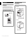
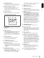
3-206-136-43 (1)
Digital Color Printer
Instructions for Use
UP-DR100
© 2001 Sony Corporation
Owner's Record
The model and serial numbers are located at the rear.
Record these number in the space provided below.
Refer to these numbers whenever you call upon your
Sony dealer regarding this product.
Model No. ____________________
Serial No. ____________________
WARNING
To prevent fire or shock hazard, do not expose the unit to
rain or moisture.
To avoid electrical shock, do not open the cabinet. Refer
servicing to qualified personnel only.
THIS APPARATUS MUST BE EARTHED.
2
For the customers in the U.S.A.
This equipment has been tested and found to comply
with the limits for a Class A digital device, pursuant to
Part 15 of the FCC Rules. These limits are designed to
provide reasonable protection again harmful
interference when the equipment is operated in a
commercial environment. This equipment generates,
uses, and can radiate radio frequency energy and, if not
installed and used in accordance with the instruction
manual, may cause harmful interference to radio
communications. Operation of this equipment in a
residential area is likely to cause harmful interference in
which case the user will be required to correct the
interference at his own expense.
You are cautioned that any changes or modifications not
expressly approved in this manual could void your
authority to operate this equipment.
This shielded interface cable recommended in this
manual must be used with this equipment in order to
comply with the limits for a digital device pursuant to
Subpart B of Part 15 of FCC rules.
Table of Contents
Introduction
Features ...................................................................4
Basic Application Example ................................4
Part Names and Functions ....................................4
Preparation
Supplied Accessories ..............................................6
Assembly ............................................................6
DIP Switch Settings ................................................7
Connections ............................................................8
Operation
Loading the Paper and Ink Ribbon ......................9
Printing from the Computer ...............................14
Adjusting Gray Balance ......................................16
Displaying the Total Quantity of Pages Printed
and Remaining Amount of Ink Ribbon or Paper ..
18
Displaying the Quantity of Pages Printed .........18
Displaying the Remaining Amount of Paper or Ink
Ribbon .............................................................18
Displaying the Firmware Version of the Printer ...
19
Miscellaneous
Precautions ...........................................................20
Safety ................................................................20
Installation ........................................................20
On Transporting the Printer ..............................21
Cleaning ............................................................21
Ink Ribbon and Paper .........................................23
Specifications ........................................................24
Error and Warning Messages .............................25
Troubleshooting ....................................................26
Index ......................................................................27
3
Introduction
Part Names and
Functions
For details, refer to the pages indicated in parentheses.
Introduction
Features
The UP-DR100 Digital Color Printer is a dye
sublimation thermal transfer printer providing high
quality, high resolution (334 dpi), and high speed
printing of computer image data on four sizes of paper
in full color (256 gradations and 16.7 million colors).
Front panel
Basic Application Example
Computer: provides
image data for printing
and printer control
signals
Rear panel
UP-DR100 Digital Color Printer
4
Features / Part Names and Functions
A ALARM indicator (25)
Lights in green when the system is initialized, or in
red when an error, such as a paper jam, occurs.
C Operation panel door
Pull the top edge to open the operation panel door.
Operation panel with door open
F PRINT Indicator (14)
Lights in green while printing.
Introduction
B Information Display (14, 18, 25)
Displays the number of pages printed, or the
amount of paper and ink ribbon remaining.
Messages are displayed when an error or warning
condition occurs.
button to display the number of pages printed or the
amount of paper and ribbon remaining.
G Ventilation holes (22)
Behind the ventilation holes panel, there is a builtin fan to prevent the thermal head from overheating
H FEED button (12, 15)
Press and hold this button for more than one
second immediately after you replace the paper
and ink ribbon in use. Several sheets of blank
paper are then fed through. In this way, soiled paper
at the beginning of the roll will be eliminated, and
paper improperly loaded at an angle will be
straightened in the paper path. Also, pressing the
FEED button for more than one second during
printing results in cancelling the number of
printings set and clearing the images stored in the
memory. The printer stops printing when the page
currently printing is completed and ejected.
I !POWER switch (14)
Press this switch to turn the printer on or off.
A EXEC Button
Press this button to print the gray scale adjustment
pattern.
B MENU Button (18)
Press to display the number of pages printed or the
amount of paper and ink ribbon remaining.
Pressing the MENU button changes the printer to
the off-line mode and turns the ONLINE indicator
off.
C Cursor Buttons (18)
Press these buttons to select the item to be
displayed on the information display.
D CALIBRATION button (16)
Press this button to adjust the gray balance.
D Maintenance door (22)
Open the maintenance door for cleaning the surface
of the paper. The roller used for removing the dust
accumulated on the surface of the paper is attached
to the door.
E ONLINE indicator (14, 18)
Lights in green when the printer is controlled only
by the computer in the on-line mode.
This indicator goes off when the printer goes offline, for example, when you press the MENU
J Paper scrap tray (6)
A margin of about 10mm is put between the current
printout and the next printout from the paper roll.
This margin of paper is cut off and ejected into the
paper scrap tray.
K Paper Output Slot
Printed pages are output from the printer here.
L SCSI Connectors (50-pin, half pitch) (7, 8)
Connect the computer used to control the printer
and connect other SCSI devices with SCSI cables to
one of these connectors. The second connector is
used as a pass-through connector when daisy
chaining with other SCSI devices. If only one of the
SCSI connectors on the printer is used, the internal
terminator should be enabled by changing the
appropriate DIP switch setting, see “DIP Switch
Settings” (page 7).
M DIP Switch (7, 8)
Determines the SCSI device ID number of the
printer, and sets the internal terminator on or off.
See “DIP Switch Settings” (page 7).
N - AC IN (Power Source) Connector (8)
Connect the supplied power cord here.
Part Names and Functions
5
Preparation
Assembly
Mount the paper scrap tray on the printer.
Supplied Accessories
Make certain you have received the following
accessories:
Preparation
Paper Scrap Tray (1)
Paper scrap tray
Power Cord (1)
To remove the Paper scrap tray
Hold both ends of the paper scrap tray and pull it
forward while pushing it down.
To accumulate the ejected printed sheets
Use of the UPA-DR100PS PRINT STACKER (not
supplied) is recommended. Printed sheets for up to one
roll can be accumulated on the stacker regardless of the
type of printing pack used.
Caution
CD-ROM (1)
Operating Manual (1)
Software License Agreement (1)
Warranty Card (1)
Service and Customer Support
Information (1)
Notes
• When taking out the printer, be careful not to hurt your
back.
• The packaging materials are needed when
transporting the printer, so we suggest you keep them.
• Before moving the printer, remove the ink ribbon and
paper.
When the UPC-R57/R57A/R68A printing pack is used,
check the location where the printer has been installed.
A space of about 20 cm (7 7/8 inches) out from the
printer, and about 20 cm (7 7/8 inches) down from the
bottom of the printer is required as shown in the
diagram.
Match the front edge of
the printer to the edge
of the installation rack.
7 7/8 inches
7 7/8 inches
If there is not enough space (as shown in the illustration
above), ejected printed sheets may pile up and clog at the
Paper Output Slot and trouble may occur.
6
Supplied Accessories
Paper and ink ribbon
For detailed information on how to install the ink ribbon
and paper, see “Loading the Paper and Ink Ribbon” on
page 9.
DIP Switch Settings
Set the SCSI ID with the DIP switches on the side panel.
The DIP switches are set as follows when shipped from
the factory.
Terminator
SCSI ID
Preparation
Terminator ON/OFF Setting
When the printer is connected as the terminating device
on the SCSI bus, set the terminator to the ON position.
Otherwise, set it to the OFF position.
Switch
ON
OFF
TERMINATOR
Internal Terminator
ON
Internal Terminator
OFF
SCSI ID Setting
Set the printer SCSI ID so that it is different from all
other devices on the SCSI bus.
If two devices have the same SCSI ID, malfunctions
may result.
SCSI ID
SCSI ID Switch
1
2
4
0
0
0
0
1
1
0
0
2
0
2
0
3
1
2
0
4
0
0
4
5
1
0
4
6
0
2
4
7
1
2
4
The SCSI ID is set to 1 as the factory setting.
DIP Switch Settings
7
Connections
Computer
The UP-DR100 can be connected to computers and
peripheral devices equipped with a SCSI interface.
Notes
SCSI Cable
(not supplied)
Preparation
• Before making connections, always turn off all
connected devices.
• Connect the power cord last.
• Refer to the operating manual of each device for
details of connections between the printer, computer
and peripherals.
• SCSI cable connectors should be firmly mated at each
end.
• The total length of SCSI cables connected to a single
host computer should not be longer than 3 meters.
• When connecting only the printer to a single host
computer, the SCSI cable should not be longer than 1
meter.
• To print, a driver is required that corresponds to the
hardware environment in which the printer is to be
used.
• Pay attention to the following when connecting the
SCSI cable.
The SCSI connector has been mounted onto the
slanting surface of the unit for easy insertion of the
cable. Be sure to insert the SCSI cable straight into the
SCSI connector as shown in the figure. If you insert
the SCSI cable into the SCSI connector at angles, this
may result in bending the small pins inside the SCSI
connector and it may not work.
To SCSI
connector
To disconnect
DIP Switch a)
To -AC IN
terminal
Power Cord (supplied)
To AC power output
a) When connecting the printer at the end of the SCSI bus,
set the internal terminator to ON. (“DIP Switch Settings”
on page 7)
Note
The proper SCSI cable to use depends on the computer
or peripheral device to be connected. Refer to the
operating manuals for details.
Also, be sure to use a shielded-type cable comforming to
the FAST SCSI (high impendance) standards.
When turning power on
Turn on any peripheral devices before turning the
computer on. Make sure that every device in the SCSI
chain is turned on.
8
Connections
Operation
Loading the Paper and
Ink Ribbon
• Hold the right and left flanges of the paper roll so that
you do not drop it, because it is heavy. Dropping may
result in an injury and may cause accumulation of dust
on the paper. Any dust on the printing surface will
result in poor printout quality.
• A built-in IC chip is located around one side of the
flange of the paper roll. Be careful not to hurt the IC
seal or give it a shock. If you do, you may not be able
to use the ink ribbon any more.
Before using the printer for the first time, confirm that
you have all of the accessories, and assemble them as
described on page 6.
After connecting the printer as described on page 8, load
the paper and ink ribbon following the steps below to
prepare for actual printing.
These steps are not required every time you print, but
only as necessary.
Hold the right and left flanges with both hands.
Operation
Notes
• The printing pack contains an ink ribbon and one
paper roll. Use the ink ribbon and the paper roll in the
carton as a set. Do not mix with other varieties of
ribbon or paper. (“Ink Ribbon and Paper” on page 23.)
• Each printing pack allows you to print the following
number of sheets.
Print
pack
UPC-R35/ UPC-R46/ UPC-R57/ UPCUPC-R35A UPC-R46A UPC-R57A R68A
Printing 400
capacity
Print
size
350
205
185
89×127 mm 102×152
mm
127×178
mm
152×204
mm
3.5×5
inches
5×7 inches
6×8
inches
4×6 inches
• The number of printouts that can be printed may not
be guaranteed if you replace the ink ribbon and paper
before the ink ribbon and paper run out.
• Place the paper roll vertically with flanges facing up
and down. If you place the paper roll horizontally, the
paper may roll around and fall. This may cause an
injury.
Flanges
• Do not detach the blue and pink spools of the ink
ribbon until you start loading the ink ribbon
• A built-in IC chip is located around one side of the
pink spool. Be careful not to hurt the IC seal or give
it a shock. If you do, you may not be able to use the
ink ribbon any more.
IC seal in which the IC
chip is built
Pink spool
Blue spool
Loading the paper and ink ribbon
When you use the printer for the first time, load the
paper and ink ribbon.
For detailed information on how to remove the paper
and ink ribbon, see page 13.
Note
Be careful that your fingers or clothes don’t get caught
in the front door or front door catch.
Loading the Paper and Ink Ribbon
9
1
Pull the top of the front door to open it.
Remove the labels.
Load the paper after matching the colors of the
flange of the paper roll and the flange holder of
the printer correctly.
Operation
2
Pull the cover up.
Thermal head
Caution
Since the thermal head is still very hot just after
printing is finished, be careful not to touch the
thermal head when placing the paper roll in the
paper holder.
3
After removing the labels attached at both sides of
the paper roll, place the paper roll in the paper
holder.
Place the paper roll in the paper holder, so the pink
flange is on the right and the blue flange is on the
left.
4
Remove the label attached at the tip of the paper,
then, while holding both ends of the paper, insert
the paper into to the slot. Feed in the paper with
your hand until the marking hole appears.
Roll the paper in properly so that it goes
in straight.
Marking hole
10
Loading the Paper and Ink Ribbon
6
Note
Hold both spools and push the blue spool into the
blue spool holders.
Be sure to remove all of the seals attached to the
paper roll. A seal remaining inside the printer may
cause problems.
5
Insert the left side of the blue spool first,
then the right side and push it until it clicks.
Close the cover.
Confirm that the tip of the paper appears.
Operation
Caution
If the tip of the paper protrudes from the platen
roller, be sure to insert the tip of the paper under the
rollers.
Rollers
Platen roller
Since the thermal head is still very hot just after
printing is finished, be careful not to touch the
thermal head when loading the ink ribbon.
7
Detach the pink spool from the blue spool. Pull it
upward and wind it until the transparent part (the
laminating part) comes to the position illustrated,
and push it into the pink spool holders.
Insert the left side of the pink spool first,
then the right side and push it until it clicks.
Note
Do not touch the printing surface of the paper roll
in the paper holder after loading it. Sweat or dust
from your hands may have an influence on the
quality of the printout.
The black marks should show on
the front of the pink spool.
Transparent part (the laminating part)
Loading the Paper and Ink Ribbon
11
8
After confirming that the spools have been properly
inserted, remove any slackness from the ink ribbon.
FEED button
Wind the blue spool.
Operation
9
After several sheets of paper are fed out, the printer
is ready to print.
Close the front door.
Turn on the printer, if it is turned off.
When you load a brand new paper roll and ink
ribbon, the printer feeds a certain amount of the
paper and is then ready to print.
When you load partially used paper roll and ink
ribbon, go to step 10.
Note
Close the front door so that both sides of the front
door are completely locked. An unlocked door may
cause a malfunction of the printer.
If you close the front door by pushing one side, both
sides of the front door may not be completely
locked.
10 Confirm that READY appears on the information
display.
Then, to straighten the paper, which might have
been loaded at angle, keep pressing the FEED
button for more than one second.
If you open the front door during operation
When you open the front door after starting to use the
printer just after loading the paper and ink ribbon, the tip
of the paper may protrude. In that case, push the paper
back so that the length of the paper protruding is less
than 5 cm, then close the front door.
If you close the door with the paper protruding, the
printed paper will not be ejected correctly. This causes
paper jamming.
Push the paper
back so that the
length of the
paper protruding
is less than 5 cm
(2 inches).
Note
Be sure to do this after loading a paper roll used
partially.
Note
Be careful not to touch the printing surface of the paper
when pushing it back. Sweat or dust from your hands
may have an influence on the quality of the printout.
Notes on storage
• Avoid placing the printer where subject to:
high temperatures,
high humidity or dust,
direct sunlight.
• After opening the bag, use the ribbon and the paper as
soon as possible.
• When storing after partial use, put the ribbon and the
paper back in their respective bags.
12
Loading the Paper and Ink Ribbon
If the ribbon breaks during use
The remaining ribbon can be used after repairing it with
adhesive tape.
1
Removing the ink ribbon and paper
1
Pull out the lower ribbon of the blue spool, attach
one edge of a strip of adhesive tape over the entire
end of the ribbon, then attach the other edge of the
adhesive tape on the end of the upper ribbon of the
pink spool.
Wind the spool Attach one edge of adhesive
to feed the
tape over the entire end of the
ribbon out.
ribbon and attach the other
edge of the adhesive tape on
the end of the upper ribbon.
Remove the scraps of paper ejected and
accumulated on the paper scrap tray.
Note
If scraps of paper have accumulated on the paper
scrap tray, the front door may not open completely.
Pull the top of the front door to open it.
3
Push the right blue spool to the left and pull it
toward you to remove the blue spool of the ink
ribbon.
4
Wind up the loose ink ribbon.
Operation
2
2
Turn the lower blue spool in the direction of the
arrow to remove the slackness of the ribbon.
Wind the spool in
the direction of the
arrow to remove the
slackness of the
ribbon.
The ribbon is ready to be used. Depending on the
position of the break in the tape, the ribbon for one
sheet of printed paper may be lost.
Loading the Paper and Ink Ribbon
13
5
Push the right pink spool to the left and pull it
toward you to remove the pink spool of the ink
ribbon.
Attach both pink and blue spools of the ink ribbon.
Printing from the
Computer
Before starting to print
• Confirm that the printer and computer are connected
(page 8).
• Confirm that the paper and the ink ribbon are correctly
installed (page 6).
• Confirm that the compatible ink ribbon and printing
paper are installed (page 23).
Printing
Operation
information display
6
ONLINE indicator
Remove the paper.
1 Pull the cover up.
2 Turn both flanges of the paper toward the inside
to wind the remaining paper.
3 Remove the paper roll.
Wind the remaining paper by turning the
flanges of the paper roll in the direction of
the arrow 2.
1
1
Turn on the printer and computer.
After a few seconds, the following message should
appear on the information display. When READY
is displayed and the ONLINE indicator is lit, the
printer is ready to print.
Caution
Since the thermal head is still very hot just after
printing is finished, be careful not to touch the
thermal head when removing the paper roll from
the paper holder.
14
Printing from the Computer
Print size
Displays the remaining amount of
paper or ink ribbon, whichever is less.
Identification of the printing pack currently
being used on the information display
Display on the
information display
Printing pack
R35
UPC-R35/R35A
R46
UPC-R46/R46A
R57
UPC-R57/R57A
R68
UPC-R68A
3 After printing is finished, the printed paper is
ejected from the output slot.
The printing time depends on the print size, ink
ribbon and the paper.
Once printing has been completed, the PRINT
indicator goes off and READY appears on the
information display again.
Notes
2
Note
Do not open the maintenance door while the printer is
printing. Doing so may have an influence on the quality
of the printout.
Operation
• Turn the printer on first.
• Don’t turn the printer on again within 5 seconds
after turning it off.
• Do not turn the computer off and on again while
it is accessing a hard or floppy disk.
Send the image data from the computer to be
printed.
The printer starts printing.
1 While the printer is receiving the image data,
the following message should appear.
Indicates the image data is being
transferred.
: Indicates 20% of the total amount of image
data. In the above example, 60% of the total
amount of image data has been transferred.
2 The printer starts printing the transferred image
data as soon as the print command is sent from
the computer.
The PRINT indicator lights and the following
message should appear.
To stop sending the image data or to stop
printing midway
Press and hold the FEED button for more than one
second. The page currently being printed is completed
and ejected. After the printout is ejected, the information
display returns to READY. The image data stored in the
memory and the number of printings set in the queue are
cancelled.
Number of pages to be printed
The color indication changes as the color printing
procedes:
StarttYELLOWtMAGENTAtCYANtLAMIt
Finsih.
About memory
Since the printer has memory for image data spooling,
image data to be printed can be transferred to the printer
while printing an image.
Printing from the Computer
15
If the printer does not print
The printer cannot print in the following cases:
• When the remaining amount of ink ribbon or the
quantity of printing is displayed on the information
display because the MENU button was pressed and the
printer is off-line, the printer cannot receive a print
command from the computer.
• When an error message is displayed on the
information display, you cannot operate the printer.
Take remedies according to the advice given in “Error
and Warning Messages” on page 25.
Operation
Notes on storing your printouts
• Avoid exposure to direct sunlight, or conditions of
high temperature and high humidity, which could
cause the colors to fade.
• Avoid applying tape to a printout, and avoid contact
with plastic objects such as erasers and desk mats.
• Do not allow alcohol or other volatile organic solvents
to come into contact with the printouts.
Adjusting Gray Balance
The gray balance differs between different packages
where ink ribbons and papers are contained as a set. To
avoid imbalance, use the ink ribbon with the paper that
is supplied as a set in the same package. Also, when a
new ribbon and paper are loaded, we recommend that
the gray balance be adjusted. The gray balance of the
printer is set to No.0 as the factory setting. This setting
is retained even when the printer is turned off.
Note
The gray balance of images cannot be adjusted during
printing.
2,7,8,9,10
3
1,6,11
ONLINE indicator
1
Press the CALIBRATION button.
The ONLINE indicator goes off and the printer is
switched to off-line.
2
Press the F and f buttons to select GRAY PATCH
PRINT.
Press F and f to display GRAY PATCH PRINT.
3
16
Adjusting Gray Balance
Press the EXEC button.
The printer returns to the on-line mode and starts
printing.
When using the UPC-R35/R35A or UPC-R46/
R46A, gray adjustment patterns Group A and
Group B are printed on two sheets separately.
When using the UPC-R57/R57A or UPC-R68A,
gray patterns Group A and Group B are printed on
one sheet.
4
Look at the printout of Group A to determine the
best gray balance from this group.
5
Next, look at the printout of Group B to determine
the best gray balance from this group, too.
6
Press the CALIBRATION button.
The ONLINE indicator goes off and the printer is
switched to off-line.
7
Press the F and f buttons to select GRAY ADJUST
[A].
The printer enters the gray balance adjustment
mode.
8
number determined in step 5.
For example, select 39 if you determined that
pattern No. 39 in the sample provides the best gray
balance.
Press G and g to display 39.
11 Press the CALIBRATION button.
The printer returns to the on-line mode, and the
ONLINE indicator lights.
Operation
Press F and f to display GRAY
ADJUST [A].
10 Press the G and g buttons to display the pattern
Press the G and g buttons to display the pattern
number determined in step 4.
For example, select 18 if you determined that
pattern No. 18 in the sample provides the best gray
balance.
Press G and g to display 18.
9
Press the F and f buttons to select GRAY ADJUST
[B].
The printer enters the gray balance adjustment
mode.
Press F and f to display GRAY
ADJUST [B].
Adjusting Gray Balance
17
To display the total number of printings
made so far since you started to use the
printer:
Select “TOTAL PRINTS”.
Displaying the Total
Quantity of Pages
Printed and Remaining
Amount of Ink Ribbon or
Paper
Press F and f to display
TOTAL PRINTS.
Total number of printings
Operation
Displaying the Quantity of Pages
Printed
3
The total number of pages printings done since turning
on the printer can be displayed. If no printings have been
done since the printer was turned on, “0” is displayed on
the information display. Also, the total number of
printings made so far since you started to use the printer
can be displayed.
Displaying the Remaining Amount
of Paper or Ink Ribbon
Press the MENU button after confirming.
The printer returns to the on-line mode, and the
ONLINE indicator lights.
The remaining amount of paper or ink ribbon can be
displayed on the information display.
1,3
2
ONLINE indicator
1,3
1
2
Press the MENU button.
The ONLINE indicator goes off and the printer is
switched to off-line.
Press the MENU button.
The ONLINE indicator goes off and the printer is
switched to off-line.
2
Press the F and f buttons to select the item you
want to be displayed.
Press F and f to display CURRENT PRINTS.
Total number of printings since turning on the printer
18
ONLINE indicator
1
Press the F and f buttons to select the item you
want to be displayed.
To display the total number of printings
since turning on the printer:
Select “CURRENT PRINTS.”
2
Displaying the Total Quantity of Pages Printed and Remaining Amount of Ink Ribbon or Paper
To display the remaining amount of the ink
ribbon:
Select “RIBBON REMAIN.”
Press F and f to display
RIBBON REMAIN.
Remaining amount of the
ink ribbon
Displaying the Firmware
Version of the Printer
The version of the firmware of the printer can be
displayed.
1,3
Type of the ink ribbon
2
ONLINE indicator
To display the remaining amount of paper:
Select “PAPER REMAIN”.
Operation
Press F and f to display
PAPER REMAIN.
Remaining amount of paper Type of the paper
3
Press the MENU button after confirming.
The printer returns to the on-line mode, and the
ONLINE indicator lights.
1
Press the MENU button.
The ONLINE indicator goes off and the printer is
switched to off-line.
2
Press the F and f buttons to display VERSION.
Press F and f to display VERSION.
Note
If the ink ribbon and paper have not been used from
the beginning, the remaining amount displayed
may be incorrect.
Version of the firmware of the printer
3
Press the MENU button after confirming.
The printer returns to the on-line mode, and the
ONLINE indicator lights.
Access the following site to get the latest information on
the printer.
http://www.sony.co.jp/DP-driver-E/
Displaying the Firmware Version of the Printer
19
Miscellaneous
Precautions
Note
Two protruberences placed on the rear of the printer
are provided to prevent the ventilation holes being
covered over by a wall, etc., when installing the printer
near the wall. These protruberences are not to be
used as feet to install the printer laying on its back.
Protruberences
Safety
Miscellaneous
• Operate the printer using the power source specified in
“Specifications” (page 24)
• Be careful not to damage the power cable by placing
or dropping heavy objects on it; it is dangerous to use
the unit with a damaged power cable.
• If you do not intend to use the unit for a long time,
disconnect the power cable.
• Unplug the power cable by grasping the plug, not the
cable itself.
• Do not disassemble the unit. There is a danger of
electric shock from the internal parts.
• Be careful not to spill water or other liquids on the
unit, or to allow combustible or metallic material to
enter the cabinet. If used with foreign matter in the
cabinet, the unit is liable to fail, or present a risk of fire
or electric shock.
• If the unit malfunctions or if a foreign body falls into
the cabinet, disconnect the power immediately and
consult your Sony service facility or your Sony dealer.
Installation
• Avoid placing the unit in a location subject to:
– mechanical vibration
– high humidity
– excessive dust
– direct or excessive sunlight
– extremely high or low temperatures
• Ventilation holes are provided on the back of the unit
to prevent the unit from overheating. Be careful not to
obstruct them with other objects or by covering the
unit with a cloth etc.
20
Precautions
On condensation
• If the printer is subjected to wide and sudden changes
in temperature, such as when it is moved from a cold
room to a warm room or when it is left in a room with
a heater that tends to produce large amounts of
moisture, condensation may form inside the printer. In
such cases the printer will probably not work properly,
and may even develop a fault if you persist in using it.
If moisture condensation forms, turn off the power and
leave the printer standing for at least one hour.
• If the printing pack is subjected to wide and sudden
changes in temperature, condensation may form on
the ink ribbon or paper inside. This will cause the
printer to malfunction. Also if the printing pack is
used in this state, spots are likely to appear on the
printout.
• To store a half-used printing pack, replace it in its
original packing and reseal the package. If possible,
keep the sealed printing pack in a cool, dark location.
To subsequently use the printing pack, place it, in its
sealed package, in a warm room for several hours.
Doing so prevents condensation from forming when
the printing pack is removed from its package.
On Transporting the Printer
Do not transport the printer with the supplied
accessories attached. Doing so may cause a malfunction.
To clean the platen roller:
Clean the platen roller gently with a soft cloth moistened
with alcohol.
Clean the platen roller gently with a soft cloth
moistened with alcohol while turning the platen roller.
Cleaning
Note
Be sure to turn off the power of the printer before
cleaning it.
When the cabinet becomes dirty
Clean the cabinet, panel and controls with a soft dry
cloth, or a soft cloth lightly moistened with a mild
detergent solution.
Do not use any type of solvent, such as alcohol or
benzine, which may damage the finish.
To clean the pinch roller:
Clean the pinch roller gently with a soft cloth moistened
with alcohol while turning the pinch roller.
Miscellaneous
After you replace the paper roll with the
new one
After you spent one paper roll and load the new one,
perform the following cleaning.
Note
Be sure to use the printer only after it has been dried
completely, if you intend to use the printer just after you
have cleaned it. If it has not been dried completely, this
may have an influence on the quality of the printout.
To clean the thermal head:
Clean the thermal head heating elements, IC cover and
ribbon guide gently with a soft cloth.
Thermal head heating elements
IC cover
Pinch roller
To clean the cleaning roller for the ink ribbon:
Clean the cleaning roller gently with a soft cloth
moistened with alcohol to remove the dust accumulated
on the roller.
Ribbon guide
Precautions
21
1
Note
The surface of the rubber roller is soft and easily
scratched. When cleaning it, be carefull not to scratch
and not to pull the surface of the rubber roller.
Remove the fan cover, and then the filter.
Fan cover
Cleaning
roller
Filter
Miscellaneous
To clean the cleaning roller used for removing
dust accumulated on the paper:
Open the maintenance door, and then clean the roller
with a soft cloth or the like moistened with alcohol.
Fan cover
2
Wash the filter with water to remove the dust.
Note
The surface of the rubber roller is soft and easily
scratched. When cleaning it, be carefull not to scratch
and not to pull the surface of the rubber roller.
Be sure to hold the
maintenance door open
while cleaning the roller.
Note
Do not rub the netting of the filter roughly.
3
After the filter has been dried completely, reset the
filter and fan cover on the front panel as they were.
Reset the filter on the fan cover correctly.
Cleaning roller
When the following symptoms appears
When the message “HEAD IN COOLING”
begins to appear on the information display
frequently:
Ventilation holes are provided on the front and rear of
the printer. Clean the filter placed on the front panel of
the printer. If the filter is dirty, the time required for
cooling the thermal head is lengthened and this causes
the printing time to become longer.
22
Precautions
Note
Be sure to attach the filter onto the fan cover correctly. If
not, dust may accumulate on the printout. This may have
an influence on the picture quality.
If white stripes or scratches appears on the
printout:
When you make printouts using the UPC-R46/R46A/
R68A self-laminating color printing pack, after you
have used several rolls of the UPC-R35/R35A/R57/
R57A self-laminating color printing pack, the printout
quality may deteriorate, for example, white stripes or
scratches may appear on the printout.
In such a case, clean the thermal head gently with a soft
cloth moistened with alcohol.
Clean both ends of the thermal head gently
with a soft cloth moistened with alcohol.
Ink Ribbon and Paper
The ink ribbon and paper are supplied as a set in the
same package and are intended to be used together.
UPC-R35/R35A Self-Laminating Color Printing
Pack
Contains color ink ribbon and paper.
Ink ribbon for printing: 1 roll
L-size print paper: 1 roll
UPC-R46/R46A Self-Laminating Color Printing
Pack
Contains color ink ribbon and paper.
Ink ribbon for printing: 1 roll
King-size print paper: 1 roll
Miscellaneous
UPC-R57/R57A Self-Laminating Color Printing
Pack
Contains color ink ribbon and paper.
Ink ribbon for printing: 1 roll
2L-size print paper: 1 roll
UPC-R68A Self-Laminating Color Printing Pack
Contains color ink ribbon and paper.
Ink ribbon for printing: 1 roll
2KG-size print paper: 1 roll
Note
When using the UPC-R57/R57A, or UPC-R68A SelfLaminating Color Printing Pack, check the location
where the printer has been installed (page 6).
Printing capacity
Print
pack
UPC-R35/ UPC-R46/ UPC-R57/ UPCUPC-R35A UPC-R46A UPC-R57A R68A
Printing 400
capacity
Print
size
350
205
185
89×127 mm 102×152
mm
127×178
mm
152×204
mm
3.5×5
inches
5×7 inches
6×8
inches
4×6 inches
However the number of sheets that can be printed may
not be guaranteed if you replace the ink ribbon and paper
before the ink ribbon and paper run out.
Ink Ribbon and Paper
23
Specifications
Miscellaneous
Power requirements
100-120 V/220-240 V AC, 50/60 Hz
Current consumption
Max. 2.7 A/1.2 A (while printing)
Operating temperature range
5 to 35°C
Operating humidity range
20 to 80%
External dimensions
Approx. 280 × 362 × 434 mm (WHD)
(11 1/8×14 3/8×17 1/8 inches)
(excluding projecting parts)
Approx. 280 × 362 × 448 mm (WHD)
(11 1/8×14 3/8×17 3/4 inches)
(including the maximum projecting
parts)
Weight
Approx. 17.5 kg (38lb 9 oz) (printer
only)
Printing system Dye sublimation thermal transfer
Thermal head 13.1 dot/mm, 2048 elements (334 dpi)
Gradations
8 bits each for yellow, magenta and
cyan
Picture size
UPC-R35/R35A: 89 × 127 mm (3.5 ×
5 inches)
UPC-R46/R46A: 102 × 152 mm (4 × 6
inches)
UPC-R57/R57A: 127 × 178 mm (5 × 7
inches)
UPC-R68A: 152 × 204 mm (6 × 8
inches)
Printable pixels UPC-R35/R35A: 1170 × 1670 dots
UPC-R46/R46A: 1341 × 1999 dots
UPC-R57/R57A: 1670 × 2341 dots
UPC-R68A: 1999 × 2683 dots
Printing time UPC-R35/R35A: Approx. 23 sec.
UPC-R46/R46A: Approx. 24 sec.
UPC-R57/R57A: Approx. 36 sec.
UPC-R68A: Approx. 40 sec.
Input connector AC IN (for power)
Control connectors
SCSI-2 interface × 2 (50-pin, halfpitch)
Accessories supplied
Paper scrap tray (1)
Power Cord (1)
CD-ROM (1)
Software License Agreement (1)
Operating Manual (1)
Warranty Card (1)
Service and Customer Support Info. (1)
Optional accessories
Self-Laminating Color Printing Pack
UPC-R35
24
Specifications
UPC-R35A
UPC-R46
UPC-R46A
UPC-R57
UPC-R57A
UPC-R68A
PRINT STACKER UPA-DR100PS
SCSI-2 Interface
Connectors
Terminator
SCSI ID setting
Transfer speed
Two 50-pin, half-pitch
Internal (DIP switch enable/disable)
0 to 7 (DIP switch selectable)
Max. 10 MB/sec (Fast SCSI)
Design and specifications are subject to change without
notice.
Error and Warning
Messages
Error and warning messages appear on the information
display under the following conditions. Please take the
remedial actions shown next to the message to correct
the condition.
Description and Remedy
PAPER END
The paper corresponding to the
designated number of sheets is
exhausted.
tLoad a new ink ribbon and paper
roll. (page 9)
PAPER ERROR
• The paper corresponding to the
designated number of sheets is
exhausted.
tLoad a new ink ribbon and paper
roll. (page 9)
• Something is wrong with the data
on the IC seal attached to the paper
roll.
tReplace the ink ribbon and
paper roll with a new ink ribbon
and paper roll. (page 9)
RIBBON END
The ink ribbon corresponding to the
designated number of sheets is
exhausted.
tLoad a new ink ribbon and paper
roll. (page 9)
RIBBON ERROR
• The ink ribbon may break.
tRepair it with adhesive tape.
(page 13)
• Something is wrong with the data
on the IC seal attached to the paper
roll.
tReplace the ink ribbon and
paper roll with a new ink ribbon
and paper roll. (page 9)
• The ink ribbon corresponding to the
designated number of sheets is
exhausted.
tLoad a new ink ribbon and paper
roll. (page 9)
Error messages
When a problem occurs, the ALARM indicator on the
front panel lights in red, and an error message appears
on the information display. Please take the remedial
actions shown next to the message to correct the
condition.
Message
Description and Remedy
DOOR OPEN
The front door is open.
tClose the front panel until it is
locked securely (page 12).
FEED ERROR
Paper cannot be fed or ejected
correctly.
tLoad the paper roll correctly.
(page 10)
MECHA TROUBLE
• The ink ribbon may break.
tRepair it with adhesive tape.
(page 13)
• The paper corresponding to the
designated number of sheets is
exhausted.
tLoad a new ink ribbon and paper
roll. (page 9)
• The ink ribbon corresponding to the
designated number of sheets is
exhausted.
tLoad a new ink ribbon and paper
roll. (page 9)
• Mechanical trouble has occurred in
the printer.
tThe ink ribbon and paper roll are
not loaded correctly. Load them
correctly. (page 9)
tIf the message does not
disappear even after performing
the above remedy. Contact your
supplier or nearest Sony Service
Center.
MEDIA MISMATCH An incompatible ink ribbon and paper
are loaded.
tLoad the compatible ink ribbon and
paper roll taken from the same
package. (page 23)
NO PAPER
The paper roll is not loaded.
tLoad paper roll.(page 9)
NO RIBBON
The ink ribbon is not loaded.
tLoad an ink ribbon.(page 9)
Miscellaneous
Message
Warning messages
When a warning condition occurs, the warning message
appears, but the ALARM indicator does not light. The
remedy is listed below next to each message.
Message
Description and remedy
HEAD IN COOLING The thermal head is too hot.
tWait for the message to disappear.
Printing will then resume
automatically.
PLEASE WAIT
The printer ejects the paper because
the printer has received the stop
command or the printer stops printing
due to some problem.
tWait for the message to disappear.
Error and Warning Messages
25
Troubleshooting
Before submitting the product for repair, please recheck
the following. If the unit still does not operate properly,
contact your supplier or nearest Sony Service Center.
Problem
Cause and Remedy
Cannot load the paper You may be trying to load the paper
with the right and left sides reversed.
tLoad the paper after matching the
colors of the flange of the paper and
the flange holder of the printer
correctly. (page 11)
Cannot load the ink
ribbon
You may be trying to load the spools of
the ink ribbon wrongly.
tLoad the ink ribbon after matching
the colors of the spools of the ink
ribbon and the spool holders of the
printer correctly. (page 11)
Miscellaneous
NO PAPER is
The paper roll is not loaded correctly.
displayed even though tLoad the paper correctly. (page 9)
paper roll is loaded.
NO RIBBON is
The ink ribbon is not loaded correctly.
displayed even though tLoad the ink ribbon correctly.
the ink ribbon is
(page 9)
loaded.
The image is printed
out of place on the
paper.
The paper is loaded at an angle. Try to
eject several sheets of paper by
keeping the FEED button pressed for
more than one second after loading.
tEjecting the paper by pressing the
FEED button helps to put the
remaining paper in the correct
position. (page 12)
Paper is left even
though PAPER END
is displayed.
This is not a malfunction. Extra sheets
of paper are provided with each roll of
paper.
tRemove the remaining paper and
load a new ink ribbon and paper
roll. (page 9)
Ink ribbon is left even This is not a malfunction. Extra ink
though RIBBON END ribbon is provided.
is displayed.
tRemove the remaining ink ribbon
and load a new ink ribbon and paper
roll. (page 9)
HEAD IN COOLING The filter may be dirty.
is displayed
tClean the filter. (page 22)
frequently.
A vertical white stripe Dust may have accumulated on the
appears on the
thermal head.
printout.
tClean the thermal head elements
with a soft dry cloth. (page 23)
26
Troubleshooting
Index
A
Accessories supplied
assembly 6
confirmation 6
Paper Scrap Tray 6
Power Cord 6
Adjusting gray balance 16
B
Basic Application Example 4
C
Cleaning
cabinet 21
cleaning roller 22
pinch roller 21
platen roller 21
thermal head 21
Connections 8
D
F
Message
error message 25
warning message 25
O
Operation 9
P
Paper and ink ribbon
loading 9
Part Names and Functions
Front panel 4
Operation panel door 5
Rear panel 4
Precautions
condensation 20
Installation 20
on transportation 21
Safety 20
Preparation 6
Printing 14
Printing pack
printing capacity 23
UPC-R35/R35A 23
UPC-R46/R46A 23
UPC-R57/R57A 23
UPC-R68A 23
R
Index
DIP Switch Settings
SCSI ID 7
terminator 7
Displaying
quantity of printing 18
remaining amount of paper or ink
ribbon 18
version of the printer 19
M
Remaining Ribbon 18
S
SCSI ID 7
Specifications 24
Features 4
G
T
Troubleshooting 26
Gray balance 16
I
Ink ribbon
if the ribbon breaks 13
Ink ribbon and paper
displaying the remaining amount
18
loading 9
removing 13
usable printing pack 23
Introduction 4
Index
27
Sony Corporation