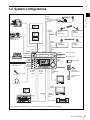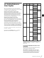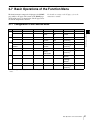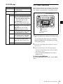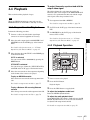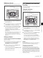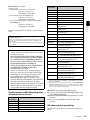
1
HD DIGITAL VIDEOCASSETTE RECORDER
HDW-S280
The supplied CD-ROM includes Operation Manual (English, French, German, and
Japanese versions) in PDF format. For details, see “1-3 Using the CD-ROM Manual”
on page 12.
OPERATION MANUAL [English]
1st Edition (Revised 5)
Important Safety Instructions
•
•
•
•
•
•
•
•
•
•
•
•
•
•
Read these instructions.
Keep these instructions.
Heed all warnings.
Follow all instructions.
Do not use this apparatus near water.
Clean only with dry cloth.
Do not block any ventilation openings. Install in accordance
with the manufacturer’s instructions.
Do not install near any heat sources such as radiators, heat
registers, stoves, or other apparatus (including amplifiers)
that produce heat.
Do not defeat the safety purpose of the polarized or
grounding-type plug. A polarized plug has two blades with
one wider than the other. A grounding type plug has two
blades and a third grounding prong. The wide blade or the
third prong are provided for your safety. If the provided plug
does not fit into your outlet, consult an electrician for
replacement of the obsolete outlet.
Protect the power cord from being walked on or pinched
particularly at plugs, convenience receptacles, and the point
where they exit from the apparatus.
Only use attachments/accessories specified by the
manufacturer.
Use only with the cart, stand, tripod,
bracket, or table specified by the
manufacturer, or sold with the apparatus.
When a cart is used, use caution when
moving the cart/apparatus combination to
avoid injury from tip-over.
Unplug this apparatus during lightning storms or when
unused for long periods of time.
Refer all servicing to qualified service personnel. Servicing
is required when the apparatus has been damaged in any
way, such as power-supply cord or plug is damaged, liquid
has been spilled or objects have fallen into the apparatus,
the apparatus has been exposed to rain or moisture, does
not operate normally, or has been dropped.
WARNING
To reduce the risk of fire or electric shock, do not
expose this apparatus to rain or moisture.
To avoid electrical shock, do not open the
cabinet. Refer servicing to qualified personnel
only.
THIS APPARATUS MUST BE EARTHED.
CAUTION
The apparatus shall not be exposed to dripping or splashing.
No objects filled with liquids, such as vases, shall be placed on
the apparatus.
This symbol is intended to alert the user to
the presence of uninsulated “dangerous
voltage” within the product’s enclosure that
may be of sufficient magnitude to constitute
a risk of electric shock to persons.
This symbol is intended to alert the user to
the presence of important operating and
maintenance (servicing) instructions in the
literature accompanying the appliance.
WARNING: THIS WARNING IS APPLICABLE FOR USA
ONLY.
If used in USA, use the UL LISTED power cord specified
below.
DO NOT USE ANY OTHER POWER CORD.
Plug Cap
Cord
Length
Rating
Parallel blade with ground pin
(NEMA 5-15P Configuration)
Type SJT, three 16 or 18 AWG wires
Minimum 1.5m, Less than 2.5 m (8 ft. 3 in.)
Minimum 10A, 125V
Using this unit at a voltage other than 120V may require the
use of a different line cord or attachment plug, or both.
To reduce the risk of fire or electric shock, refer servicing to
qualified service personnel.
2
WARNING: THIS WARNING IS APPLICABLE FOR OTHER
COUNTRIES.
1. Use the approved Power Cord (3-core mains lead) /
Appliance Connector / Plug with earthing-contacts that
conforms to the safety regulations of each country if
applicable.
2. Use the Power Cord (3-core mains lead) / Appliance
Connector / Plug conforming to the proper ratings (Voltage,
Ampere).
If you have questions on the use of the above Power Cord /
Appliance Connector / Plug, please consult a qualified service
personnel.
For the customers in the U.S.A.
This equipment has been tested and found to comply with the
limits for a Class A digital device, pursuant to Part 15 of the
FCC Rules. These limits are designed to provide reasonable
protection against harmful interference when the equipment is
operated in a commercial environment. This equipment
generates, uses, and can radiate radio frequency energy and,
if not installed and used in accordance with the instruction
manual, may cause harmful interference to radio
communications. Operation of this equipment in a residential
area is likely to cause harmful interference in which case the
user will be required to correct the interference at his own
expense.
For the customers in Taiwan only
WARNING
Excessive sound pressure from earphones and headphones
can cause hearing loss.
In order to use this product safely, avoid prolonged listening at
excessive sound pressure levels.
For kundene i Norge
Dette utstyret kan kobles til et IT-strømfordelingssystem.
You are cautioned that any changes or modifications not
expressly approved in this manual could void your authority to
operate this equipment.
All interface cables used to connect peripherals must be
shielded in order to comply with the limits for a digital device
pursuant to Subpart B of Part 15 of FCC Rules.
For the customers in Europe
This product with the CE marking complies with both the EMC
Directive and the Low Voltage Directive issued by the
Commission of the European Community.
Compliance with these directives implies conformity to the
following European standards:
• EN60065 : Product Safety
• EN55103-1 : Electromagnetic Interference(Emission)
• EN55103-2 : Electromagnetic Susceptibility(Immunity)
This product is intended for use in the following
Electromagnetic Environments:
E1 (residential), E2 (commercial and light industrial), E3
(urban outdoors), E4 (controlled EMC environment, ex. TV
studio)
The manufacturer of this product is Sony Corporation, 1-7-1
Konan, Minato-ku, Tokyo, Japan.
The Authorized Representative for EMC and product safety is
Sony Deutschland GmbH, Hedelfinger Strasse 61, 70327
Stuttgart, Germany. For any service or guarantee matters
please refer to the addresses given in separate service or
guarantee documents.
CAUTION
The unit is not disconnected from the AC power source
(mains) as long as it is connected to the wall outlet, even if the
unit itself has been turned off.
3
AVERTISSEMENT
Afin de réduire les risques d’incendie ou
d’électrocution, ne pas exposer cet appareil à la
pluie ou à l’humidité.
Afin d’écarter tout risque d’électrocution, garder
le coffret fermé. Ne confier l’entretien de
l’appareil qu’à un personnel qualifié.
CET APPAREIL DOIT ÊTRE RELIÉ À LA
TERRE.
ATTENTION
Eviter d’exposer l’appareil à un égouttement ou à des
éclaboussures. Ne placer aucun objet rempli de liquide,
comme un vase, sur l’appareil.
AVERTISSEMENT
1. Utiliser un cordon d’alimentation approuvé (conducteur
d’alimentation 3 âmes)/connecteur d’appareil/prise avec
contacts de mise à la terre conforme aux règles de sécurité
de chaque pays si applicable.
2. Utiliser un cordon d’alimentation approuvé (conducteur
d’alimentation 3 âmes)/connecteur d’appareil/prise
conforme aux valeurs nominales (tension, ampérage)
correctes.
S’adresser à un personnel de service qualifié pour toute
question concernant l’emploi du cordon d’alimentation/
connecteur d’appareil/prise ci-dessus.
Pour les clients en Europe
Ce produit portant la marque CE est conforme à la fois à la
Directive sur la compatibilité électromagnétique (EMC) et à la
Directive sur les basses tensions émises par la Commission
de la Communauté Européenne.
La conformité à ces directives implique la conformité aux
normes européennes suivantes :
• EN60065 : Sécurité des produits
• EN55103-1 : Interférences électromagnétiques (émission)
• EN55103-2 : Sensibilité électromagnétique (immunité)
Ce produit est prévu pour être utilisé dans les environnements
électromagnétiques suivants :
E1 (résidentiel), E2 (commercial et industrie légère), E3
(urbain extérieur) et E4 (environnement EMC contrôlé, ex.
studio de télévision).
Le fabricant de ce produit est Sony Corporation, 1-7-1 Konan,
Minato-ku, Tokyo, Japon.
Le représentant autorisé pour EMC et la sécurité des produits
est Sony Deutschland GmbH, Hedelfinger Strasse 61, 70327
Stuttgart, Allemagne. Pour toute question concernant le
service ou la garantie, veuillez consulter les adresses
indiquées dans les documents de service ou de garantie
séparés.
4
ATTENTION
Cet appareil n’est pas déconnecté de la source d’alimentation
secteur tant qu’il est raccordé à la prise murale, même si
l’appareil lui-même a été mis hors tension.
AVERTISSEMENT
Une pression acoustique excessive en provenance des
écouteurs ou du casque peut provoquer une baisse de l’acuité
auditive.
Pour utiliser ce produit en toute sécurité, évitez l’écoute
prolongée à des pressions sonores excessives.
WARNUNG
Um die Gefahr von Bränden oder elektrischen
Schlägen zu verringern, darf dieses Gerät nicht
Regen oder Feuchtigkeit ausgesetzt werden.
Um einen elektrischen Schlag zu vermeiden, darf
das Gehäuse nicht geöffnet werden. Überlassen
Sie Wartungsarbeiten stets nur qualifiziertem
Fachpersonal.
DIESES GERÄT MUSS GEERDET
WERDEN.
VORSICHT
Das Gerät ist nicht tropf- und spritzwassergeschützt. Es
dürfen keine mit Flüssigkeiten gefüllten Gegenstände, z. B.
Vasen, darauf abgestellt werden.
Für Kunden in Deutshland
Entsorgungshinweis: Bitte werfen Sie nur entladene Batterien
in die Sammelboxen beim Handel oder den Kommunen.
Entladen sind Batterien in der Regel dann, wenn das Gerät
abschaltet und signalisiert „Batterie leer“ oder nach längerer
Gebrauchsdauer der Batterien „nicht mehr einwandfrei
funktioniert“. Um sicherzugehen, kleben Sie die Batteriepole
z.B. mit einem Klebestreifen ab oder geben Sie die Batterien
einzeln in einen Plastikbeutel.
WARNUNG
Zu hoher Schalldruck von Ohrhörern und Kopfhörern kann
Gehörschäden verursachen.
Um dieses Produkt sicher zu verwenden, vermeiden Sie
längeres Hören bei sehr hohen Schalldruckpegeln.
WARNUNG
1. Verwenden Sie Netzkabel (dreiadrig), Geräteanschlüsse
und Netzkabelstecker mit Masseleitung, die den
Sicherheitsrichtlinien des jeweiligen Landes entspricht.
2. Verwenden Sie Netzkabel (dreiadrig), Gerteanschlsse und
Netzkabelstecker mit Masseleitung, die den vor Ort
herrschenden Spannungsanforderungen (Spannug,
Stromstrke) entsprechen.
Bei Frage ber die Eignung und Sicherheit von Netzkabein
(dreiadrig), Gerteanschlssen und Netzkabelsteckern wenden
Sie sich bitte an einen qualifizierten Electrotechniker.
Für Kunden in Europa
Dieses Produkt besitzt die CE-Kennzeichnung und erfüllt die
EMV-Richtlinie sowie die Niederspannungsrichtlinie der EGKommission.
Angewandte Normen:
• EN60065 : Sicherheitsbestimmungen
• EN55103-1: Elektromagnetische Verträglichkeit
(Störaussendung)
• EN55103-2: Elektromagnetische Verträglichkeit
(Störfestigkeit)
Für die folgenden elektromagnetischen Umgebungen:
E1 (Wohnbereich), E2 (kommerzieller und in beschränktem
Maße industrieller Bereich), E3 (Stadtbereich im Freien) und
E4 (kontrollierter EMV-Bereich, z.B. Fernsehstudio).
Der Hersteller dieses Produkts ist Sony Corporation, 1-7-1
Konan, Minato-ku, Tokyo, Japan.
Der autorisierte Repräsentant für EMV und Produktsicherheit
ist Sony Deutschland GmbH, Hedelfinger Strasse 61, 70327
Stuttgart, Deutschland. Bei jeglichen Angelegenheiten in
Bezug auf Kundendienst oder Garantie wenden Sie sich bitte
an die in den separaten Kundendienst- oder
Garantiedokumenten aufgeführten Anschriften.
ACHTUNG
Solange das Netzkabel an eine Netzsteckdose
angeschlossen ist, bleibt das Gerät auch im ausgeschalteten
Zustand mit dem Strommetz verbunden.
5
Table of Contents
Chapter 1 Overview
1-1
1-2
1-3
Features .................................................................. 10
System Configurations .......................................... 11
Using the CD-ROM Manual.................................... 12
1-3-1
Preparations ...............................................................12
1-3-2
Reading the CD-ROM Manual.................................. 12
Chapter 2 Names and Functions of Parts
2-1
Front Panel ............................................................. 13
2-1-1
Menu Operation Section............................................ 14
2-1-2
Tape Transport Section ............................................. 15
2-1-3
Display Window........................................................ 16
2-2
Rear Panel............................................................... 20
Chapter 3 Preparations
3-1
3-2
3-3
3-4
3-5
3-6
3-7
6
Table of Contents
Preparing Power Sources...................................... 22
3-1-1
Supplying Power .......................................................22
3-1-2
Using the Battery Pack .............................................. 23
Using a Stand ......................................................... 24
Connections ........................................................... 25
Handling Cassettes ................................................ 26
3-4-1
Usable Cassettes ........................................................ 26
3-4-2
Loading/Ejecting Cassettes ....................................... 26
3-4-3
Preventing Accidental Erasures.................................26
Setting Reference Video Signals .......................... 27
Setting Timecode ................................................... 28
3-6-1
Setting an Initial Value and Recording
Timecode ................................................................... 28
3-6-2
Synchronizing the Internal Timecode Generator
with an External Signal .............................................29
3-6-3
Synchronizing the Internal Timecode Generator
with a Playback Timecode – Timecode Recording
during Auto Editing................................................... 30
3-6-4
Converting Timecode in 24- or 25-Frame Mode
Playback (TC CONV) ............................................... 30
Basic Operations of the Function Menu .............. 31
3-7-1
Configuration of the Function Menu .........................31
3-7-2
Function Menu Item List ...........................................32
3-7-3
Basic Operations........................................................35
3-8
Superimposed Character Information ..................36
3-9
Using a "Memory Stick" .........................................38
3-9-1
Notes on "Memory Stick"..........................................38
Chapter 4 Recording and Playback
4-1
Recording ................................................................40
4-1-1
Preparations for Recording ........................................40
4-1-2
Recording Operation..................................................40
4-2
Back Space Editing.................................................41
4-3
Sequential Recording .............................................41
4-4
Playback ..................................................................43
4-4-1
Preparations for Playback ..........................................43
4-4-2
Playback Operation....................................................43
4-4-3
Jog/Shuttle Mode playback........................................44
Chapter 5 Assemble Editing
5-1
Overview ..................................................................45
5-1-1
Assemble Editing.......................................................45
5-2
Automatic Editing ...................................................45
5-2-1
Setting the Edit Points ...............................................45
5-2-2
Modifying and Deleting Edit Points ..........................46
5-2-3
Cueing up to Edit Points and Prerolling ....................47
5-2-4
Preview ......................................................................48
5-2-5
Performing Automatic Editing ..................................49
5-2-6
First Edit Function .....................................................50
Chapter 6 Shot Mark/Shot Data
6-1
Overview ..................................................................51
6-1-1
Shot Mark/Shot Data Function Features....................51
7-1
7-2
Stop Code ................................................................52
Stop Code Operation ..............................................52
Chapter 7 Stop Code
Table of Contents
7
7-2-1
7-2-2
7-2-3
Detecting the Stop Code............................................ 52
Recording the Stop Code...........................................53
Erasing the Stop Code ...............................................54
Chapter 8 UMID Functions
8-1
8-2
8-3
Overview of UMID Functions................................. 55
Recording UMIDs ................................................... 55
UMID Output and Display ...................................... 58
8-3-1
UMID Output Settings ..............................................58
8-3-2
UMID Display ........................................................... 58
Chapter 9 Setup Menus
9-1
9-2
Setup Menu Configuration .................................... 60
Setup Menu Operations ......................................... 60
9-2-1
Displaying Setup Menus ........................................... 60
9-2-2
Setting Setup Menu ................................................... 61
9-2-3
Menu Bank Operations (menu items B01 to
B12) ........................................................................... 62
9-3
Items in the Basic Setup Menu ............................. 63
9-4
Items in the Extended Setup Menu....................... 66
Chapter 10 Maintenance and Inspection
10-1
Removing a Cassette When Tape Slack
Occurs .................................................................... 79
10-2
Head Cleaning ........................................................ 79
10-3
Error Messages ...................................................... 80
10-4
Warning Messages................................................. 82
10-5
Moisture Condensation ......................................... 83
10-6
Regular Checks ...................................................... 83
10-6-1 Digital Hours Meter...................................................83
10-6-2 Maintenance Timings ................................................84
10-7
LCD Monitor............................................................ 85
Appendixes
Specifications...................................................................... 86
Index .................................................................................... 91
8
Table of Contents
For the customers in the U.S.A. and Canada
Note (Video set up amount)
The video setup amount is set to 0% at the factory.
If necessary, you can change the amount using
setup menu item 713.
For details on setup menu item 713, see page 74.
9
Chapter 1 Overview
Overview
1-1 Features
The HDW-S280 is a digital portable videocassette recorder
for the HDCAM format.
The unit has the features described below.
Rich variety of input and output signals
The HD4:2:2 component video signal is input as an HDSDI signal based on the SMPTE292M standards and is
recorded in HDCAM format. The following input and
output signals are supported:
• HD-SDI (high-definition serial digital interface) video
and four-channel audio input and output
• SDI video and four-channel audio output
• SD composite output
• Two-channel analog audio input and output
• Timecode input and output
• Reference-signal input and loop-through output
Compact size replaceable with a DNW-A28
The HDW-S280 HDCAM format portable video recorder
has the same size, weight, and power consumption as the
DNW-A28 Betacam SX format portable video recorder,
which enables you to replace a DNW-A28 with this unit.
The unit accepts an S cassette.
Playback compatibility with Betacam, Betacam
SP, Betacam SX
Besides recording and playback in HDCAM format, it can
play tapes recorded in Betacam, Betacam SP, or Betacam
SX formats, allowing you to make effective use of
Betacam, Betacam SP, and Betacam SX cassettes recorded
in the past.
Control Panel
The unit is equipped with an LCD monitor on the front
panel, which enables you to view materials on the unit
without using an external video monitor. The jog and
shuttle functions using the search dial allow searching for
a desired picture easily for effective cueing up and editing.
AC and DC power
The unit can be operated with a variety of power sources,
such as DC power using a battery pack or an AC adaptor
and an AC power source. Applicable battery packs are the
10
Features
Chapter
1
BP-GL65/GL95 and BP-L60(A)/L90(A)/L60S/L80S
(lithium-ion batteries) and BP-M50/M100 (nickel hydrate
batteries). The unit can operate for about 80 minutes with a
BP-GL95 battery pack mounted. To mount a battery pack,
attach an optional BKP-L551 Battery Adaptor.
Built-in up-converter and down-converter
The HDW-S280 has a built-in up-converter to convert SD
format to the HD format and down-converter to convert
HD format to the SD format. When an SD-format tape is
played, the signal is converted to HD format and output.
When an HD-format tape is played, the signal is converted
to SD format and output.
If the system frequency is set to 24PsF or 23.98PsF, the
down-converted signal is not output.
Assemble editing
By connecting two HDW-S280 units, you can perform
assemble editing. For improved effect efficiency, various
functions such as setting and modifying edit points,
preview, and review, are available.
Both interlace and progressive recording/
playback
When using the HDCAM format, 59.94i, 50i , 29.97PsF,
25PsF, 24PsF, and 23.98PsF mode recording and playback
can be selected from a menu. When 59.94i or 29.97PsF is
selected, a Betacam SX cassette recorded in NTSC or
analog Betacam cassette can be played. When 50i or 25PsF
is selected, a Betacam SX cassette recorded in PAL or
analog Betacam cassette can be played. Characteristics of
a Betacam SP cassette recorded in PAL in 50i or 25PsF
mode are the same as those when a Betacam cassette is
played.
1-2 System Configurations
SDI OUT
Chapter 1 Overview
HD SDI
OUTPUT
MW output system
SP
HD camera
Analog cassette
HD SDI
OUTPUT
SX
Digital
demodulator
Digital
modulator
Analog
demodulator
Analog
modulator
SDI OUT
HDCAM
RM-280
Editing Controller
Digital cassette
AUDIO
OUTPUT
COMPOSITE
OUT
HD SDI
REMOTE INPUT
- AC IN
HDW-S280
REMOTE 9P
DC IN 12 V
BVE-series editor
REMOTE 9P
VIDEO
CONTROL
PB
13
LEVEL
DISPLAY
REC LEVEL
13
CHARACTR
ON
PB/EE
PB
CONFI
ENABLE
CTL/TC
TC
ASSEMBLE
OFF
TCG SET
24
24
R/P LEVEL CTL
HKDV-900
HKDV-900
video control unita)
AUDIO
INPUT
PHONES
AC power source
EJECT
VAR
LEVEL
PRESET
REC INHI
EMPH
0
–10
–20
–30
–40
1
0
–10
–20
–30
–40
2
59.94i
EMPH
3
4
INPUT :
CH1 IN :
CH2 IN :
OUT :
MONI L :
MONI R :
HD
ANA
–60
COND
–4
+4
1
BANK 2
2 D-STOP
DOLBY NR
DC power source
MENU
RESET
PUSH
PITCH CTL JOG/SHUTTLE
Memory Stick
PREROLL
P ROLL
SDI ASMBL CONFI ON RECORDER
LTC DF VITC LTC EXT-LTC R-RUN REM:00M
HOME
SHIFT
EMPH EMPH
MULTI CONTROL REMOTE
00:00:00:00.
ON
PHONES
OFF
REW
PLAY
F FWD
STOP
REC
PAUSE
PAGE
KEY INHI
ON
HOME
OFF
STANDBY
AUDIO
OUTPUT/
INPUT
HD SDI
OUTPUT/
INPUT
COMPOSITE
OUT
Microphone
BKP-L551
battery adaptor
Sony BP-series
battery
SD video monitor
Headphones
HD SDI
OUTPUT
HDCAM
REMOTE
9P
HDW-2000-series
AUDIO
MONITOR
OUT
HD video monitor
Audio monitor
a) If an HKDV-900 is connected, be sure to check that the version of the HKDV-900 is V2.00 or higher.
System Configurations
11
1-3 Using the CD-ROM
Manual
Chapter 1 Overview
The supplied CD-ROM includes versions of the Operation
Manual for the HDW-S280 in English, Japanese, French,
and German in PDF format.
1-3-1 Preparations
The following program must be installed on your computer
in order to read the operation manuals contained on the
CD-ROM.
• Adobe Reader Version 6.0 or higher
Memo
If Adobe Reader is not installed, you can download it from
the following URL:
http://www.adobe.com/
Adobe and Adobe Reader are trademarks of Adobe Systems Incorporated in
the United States and/or other countries.
1-3-2 Reading the CD-ROM Manual
To read the operation manual contained on the CD-ROM,
do the following.
1
Insert the CD-ROM in your CD-ROM drive.
A cover page appears automatically in your browser.
If it does not appear automatically in the browser,
double-click on the index.htm file on the CD-ROM.
2
Select and click on the operation manual that you want
to read.
This opens the PDF file of the operation manual.
Memo
The files may not be displayed properly, depending on the
version of Adobe Reader. In such a case, install the latest
version you can download from the URL mentioned in “13-1 Preparations” above.
Note
If you have lost or damaged the CD-ROM, you can
purchase a new one to replace it. Contact your Sony service
representative.
12
Using the CD-ROM Manual
Names and Functions of
Parts
Chapter
2
0 Cassette
comportment
HDW-S280
EJECT
qa EJECT button
1 Power switch
2 AC power indicator
3 PB LEVEL
adjustment knobs
4 REC LEVEL
adjustment knobs
PB LEVEL
13
DISPLAY
REC LEVEL
13
CHARACTR
ON
PB/EE
PB
CONFI
ENABLE
CTL/TC
TC
ASSEMBLE
OFF
TCG SET
24
24
R/P LEVEL CTL
5 R/P LEVEL CTL switch
6 LEVEL adjustment knob
VAR
LEVEL
PRESET
REC INHI
EMPH
0
–10
–20
–30
–40
1
EMPH
0
–10
–20
–30
–40
2
3
4
INPUT :
CH1 IN :
CH2 IN :
OUT :
MONI L :
MONI R :
HD
ANA
–60
COND
–4
+4
1
BANK 2
2 D-STOP
DOLBY NR
P ROLL
MULTI CONTROL REMOTE
qs REMOTE button
MENU
RESET
PUSH
PITCH CTL JOG/SHUTTLE
PREROLL
59.94i
LTC
HOME
SHIFT
EMPH EMPH
Chapter 2 Names and Functions of Parts
2-1 Front Panel
SDI ASMBL CONFI ON RECORDER
DF VITC LTC EXT-LTC R-RUN REM:00M
00:00:00:00.
ON
PHONES
7 PHONES jack
OFF
ON
8 REC INHI switch
and indicator
REW
PLAY
F FWD
STOP
REC
PAUSE
PAGE
KEY INHI
HOME
OFF
STANDBY
9 KEY INHI switch
Menu operation section
a Power switch
Turns the unit ON and OFF.
For details, see “3-1-1 Supplying Power” on page 22.
b AC power indicator
Lights while the POWER switch on the rear panel is set to
ON and AC power is supplied.
c PB LEVEL adjustment knobs
Adjust the audio playback level by channel for channels 1
to 4 when the R/P LEVEL CTL switch is set to VAR.
Which channels can be adjusted is set with setup menu
item 826.
For details on setup menu item 826, see page 76.
Tape transport section
d REC LEVEL adjustment knobs
Adjust the audio recording level by channel for audio input
to this unit when the R/P LEVEL CTL switch is set to
VAR. Which channels can be adjusted is set with setup
menu item 826.
For details on setup menu item 826, see page 76.
The PB LEVEL adjustment knobs and REC LEVEL
adjustment knobs can be used for controlling four-channel
recording level or four-channel playback level if you set
thie option with setup menu item 826. In this case, each
knob controls channel indicated below.
Adjustment knob
Recording
channel
Playback
channel
REC LEVEL 1
Channel 1
Channel 3
Front Panel
13
Adjustment knob
Recording
channel
Playback
channel
REC LEVEL 2
Channel 2
Channel 4
PB LEVEL 1
Channel 3
Channel 1
PB LEVEL 2
Channel 4
Channel 2
Chapter 2 Names and Functions of Parts
e R/P LEVEL CTL switch
VAR: Enables adjustment with the PB LEVEL adjustment
knobs or REC LEVEL adjustment knobs while you
view the audio level meter in E-E mode.
PRESET: Presets to fixed levels. Levels cannot be
adjusted with the PB LEVEL adjustment knobs or
REC LEVEL adjustment knobs.
For details on setup menu item 006, see page 63.
2-1-1 Menu Operation Section
3 MENU button
f LEVEL adjustment knob
Adjusts the volume of the headphones connected to the
PHONES jack.
4 DISPLAY
button
5 RESET
button
1 Function buttons
2 Display window
DISPLAY
For Switching to E-E mode, see “ To monitor in E-E
mode” on page 16.
CHARACTR
ON
PB/EE
PB
CONFI
ENABLE
CTL/TC
TC
ASSEMBLE
OFF
TCG SET
SHIFT
HOME
EMPH
EMPH EMPH
0
–10
–20
–30
–40
1
59.94i
EMPH
0
–10
–20
–30
–40
2
3
4
INPUT :
CH1 IN :
CH2 IN :
OUT :
MONI L :
MONI R :
HD
ANA
–60
COND
–4
+4
1
BANK 2
2 D-STOP
DOLBY NR
MULTI CONTROL
MENU
RESET
PUSH
PITCH CTL
P ROLL
SDI ASMBL CONFI ON RECORDER
LTC DF VITC LTC EXT-LTC R-RUN REM:00M
00:00:00:00.
PAGE
g PHONES (headphones) jack
Connect headphones.
h REC INHI switch and indicator
ON: Recording on the tape is inhibited, regardless of the
state of the cassette’s erasure prevention plug. The
REC INHI indicator lights.
OFF: Recording on the tape is enabled when the cassette’s
erasure prevention plug is set to the original position.
HOME
8 MULTI CONTROL knob
7 PAGE/HOME button
6 SHIFT button
a Function buttons
Select and set menu items displayed in the display window.
i KEY INHI switch
When this switch is set to ON, the functions of the buttons
selected with setup menu item 118 are inhibited.
b Display window
Displays menus, audio level meters, and data such as time
data or meta-data. The DISPLAY button let you switch to
the video monitor display.
For details on setup menu item 118, see page 66.
For details, see “2-1-3 Display Window” on page 16.
j Cassette compartment
Insert a cassette here.
c MENU button
Displays a setup menu item in the time data display area of
the display window.
k EJECT button
Press to eject the cassette. The cassette mark in the display
window flashes while the cassette is being ejected.
For details on the setup menu operations, see “9-2 Setup
Menu Operations” on page 60.
l REMOTE button
Selects the operation mode of this unit.
When the button is not lit, the unit is controlled from the
front panel of this unit. Normally use this status.
When the button has been pressed and is lit, this unit is
controlled from the device connected to the REMOTE 9P
connector. In this case, all VTR operations using this unit’s
front panel are disabled except those of the STOP and
EJECT buttons.
When two HDW-S280 units are connected, press this
button on the player VTR to make it lit.
14
You can determine which tape transport buttons on the
front panel are to be enabled when the REMOTE button is
lit with setup menu item 006.
Front Panel
d DISPLAY button
Switches the operation display to the video monitor display
and vice versa.
e RESET button
Resets the CTL data displayed in the display window or the
initial value of the timecode generator.
f SHIFT button
Switches between functions for any button with two
functions.
g PAGE/HOME button
Switches pages of the function menu. When you press this
button together with the SHIFT button, the HOME page of
the function menu is displayed.
h MULTI CONTROL knob
Sets value for the menu or timecode. When you press the
knob, the units for adjustment become larger, and when
you press it again, the unit return to the original value.
9 PREROLL button
0 Search dial and
indicator
qa JOG/SHUTTLE
button
JOG/SHUTTLE
PREROLL
e STANDBY indicator
Lights while the tape drum is rotating with tension applied
(standby on). It goes dark when the drum stops rotating and
tension is released (standby off).
To protect the tape, the unit normally changes to standby
off mode when stop or pause mode continues for longer
than eight minutes. If you operate a search dial or any of the
tape transport buttons other than the PAUSE button while
the unit is in standby off mode, the unit changes to standby
on mode and enters the mode called by the button or dial
that you pressed.
By pressing the SHIFT button together with the STOP
button, you can switch between standby on and standby off
mode manually.
Tape protection settings are made with setup menu items
500s.
Chapter 2 Names and Functions of Parts
2-1-2 Tape Transport Section
d F FWD (fast forward) button
Press this button to fast-forward a tape.
When using a tape on which shot marks have been
recorded, pressing this button together with the SHIFT
button cues up the next shot mark position.
For details on the setup menu items 500s, see page 69.
REW
PLAY
F FWD
STOP
REC
PAUSE
STANDBY
8 PAUSE button
7 REC button
6 STOP button
5 STANDBY indicator
4 F FWD button
3 Servo indicator
2 PLAY button
1 REW button
a REW (rewind) button
Press this button to rewind the tape.
When using a tape on which shot marks have been
recorded, pressing this button together with the SHIFT
button cues up the previous shot mark position.
b PLAY button
Press this button to start playback. Recording starts when
you press this button together with the REC button. If you
press this button only during recording, recording stops,
and the unit enters playback mode.
When a Betacam SX cassette is being played, pressing this
button together with the SHIFT button displays the shot
data on the video monitor. The shot data can be
superimposed on the character information.
f STOP button
Press to stop playback or recording. When you stop
playback, the monitor displays E-E or still picture
playback, depending on the settings for PB/EE on the
HOME page of the function menu.
By pressing this button together with the SHIFT button,
you can switch between standby on and standby off
manually.
When setup menu item 105 is set to ON, this button flashes
if the reference video signal specified by OUT REF on the
P2 VIDEO page of the function menu or setup menu item
309 is not being input.
For details on setup menu item 105, see page 66 and for
309, see page 68.
For details on the settings for PB/EE and OUT REF of the
function menu, see “3-7 Basic Operations of the Function
Menu” on page 31.
For more details on the reference video signal settings, see
“3-5 Setting Reference Video Signals” on page 27.
g REC (record) button
Press together with the PLAY button to start recording.
When two HDW-S280 units are connected, this button
allows you to perform sequential recording from one unit
to the other.
For details, see “4-3 Sequential Recording” on page 41.
c Servo indicator
Lights while the drum servo and capstan servo are locked.
Front Panel
15
To monitor in E-E mode
You can monitor input signals in E-E mode by pressing this
button in stop mode. The button lights when pressed. To
return to the original picture, press the STOP button. You
can view E-E video during playback, search, fast forward,
and rewind while pressing this button.
For details on the setup menu item 001, see page 63, and
for 401, see page 69.
j Search dial and indicator
The outer ring is for shuttle playback, and the inner dial is
for jog playback. Press the JOG/SHUTTLE button to make
it lit and turn the ring or dial for playback in jog or shuttle
mode. Turning the dial clockwise plays a tape in the
forward direction (the G indicator lights). Turning the dial
counterclockwise plays a tape in the reverse direction (the
g indicator lights). When the tape stops, the s indicator
lights.
Setting for setup menu item 101 enables a direct search
operation that enables the search dial operation without
pressing the JOG/SHUTTLE button (direct jog/shuttle
mode).
Note
When a Betacam, Betacam SP or Betacam SX tape is
played, you cannot monitor E-E video.
Chapter 2 Names and Functions of Parts
h PAUSE button
Pauses an operation (when pressed during recording or
playback). You can execute back space editing with use of
this button.
For details on back space editing, see “4-2 Back Space
Editing” on page 41.
For details on setup menu item 101, see page 66.
k JOG/SHUTTEL button
Press to enter search mode. Each time you press this
button, jog and shuttle mode are toggled, and the selected
mode is indicated in the display window.
i PREROLL button
Cues up the preroll point. You can set the preroll time and
the status after prerolling with setup menu items 001 and
401.
2-1-3 Display Window
Operation display
1 Menu area
2 Audio level meters
3 Audio data
CHARACTR
ON
PB/EE
PB
CONFI
ENABLE
CTL/TC
TC
ASSEMBLE
OFF
TCG SET
HOME
EMPH
EMPH EMPH
0
–10
–20
–30
–40
1
0
–10
–20
–30
–40
2
3
Front Panel
4
INPUT :
CH1 IN :
CH2 IN :
OUT :
MONI L :
MONI R :
HD
ANA
–60
COND
–4
+4
1
BANK 2
2 D-STOP
DOLBY NR
LTC
4 Condition area
P ROLL
59.94i
SDI ASMBL CONFI ON RECORDER
DF VITC LTC EXT-LTC R-RUN REM:00M
00:00:00:00.
a Menu area
Normally displays the function menu. When you press the
MENU button, the functions of the function buttons used
in setup menu operations are indicated. Depending on the
function of the button, a white bar lights or flashes below
the function name to indicate the current status.
16
EMPH
5 Format area
6 Timecode setup area
7 Time data display area
b Audio level meter
EMPH
EMPH EMPH
0
–10
–20
–30
–40
1
Dolby noise reduction manufactured under license from Dolby Laboratories
Licensing Corporation.
“Dolby” and the double-D symbol are trademarks of Dolby Laboratories
Licensing Corporation.
EMPH
0
–10
–20
–30
–40
2
3
A DATA/EMPH indicator
B Audio level meters
4
d Condition area
HD
COND
C Channel indicators
A DATA/EMPH indicator
DATA: Lights if an audio signal is recognized as a data
signal in record, E-E or play mode.
EMPH: Lights if EMPHASIS on the P3 AUDIO page of
the function menu is set to ON.
B Audio level meters
Display the recording and playback audio levels of the four
audio channels (CH-1 to CH-4).
C Channel indicators
Display the audio channels. The channels selected with
setup menu item 826 are shown in green to indicate that
they are adjustable.
BANK 2
D-STOP
P ROLL
B Channel condition display
C DC operation and remaining battery power
display
D Menu bank display
E Stop code display
F Jog/shuttle display
A Format display
Displays the format of the cassette in use.
If you start recording on a Betacam SX, Betacam SP, or
Betacam cassette, the cassette mark flashes. When a
cassette is being ejected, the cassette mark also flashes.
B Channel condition display
Displays the playback condition on a scale of three levels.
For details on setup menu item 826, see page 76.
C DC operation and remaining battery power display
Lights while the unit is operating on DC power.
When the unit is operated with a battery pack, a slash is
displayed and flashes when the battery power is nearly
exhausted.
D Headroom indicator
Displays the headroom for the audio circuit set with
maintenance menu item M370.
D Menu bank display
Shows the menu bank number that has the same menu data
as currently being used.
For details on the maintenance menu item M370 refer to
the maintenance manual.
E Stop code display
Lights when a stop code can be detected. When the stop
code is detected, the display flashes. When you cue up the
shot mark, the type of the cued-up shot mark appears.
c Audio data
Displays the audio data.
INPUT: Input signal selected with AUDIO IN on the P3
AUDIO page of the function menu.
CH1 IN: Input audio level for channel 1 set with the setup
menu item 834.
CH2 IN: Input audio level for channel 2 set with the setup
menu item 834.
OUT: Output audio level set with the setup menu item 812.
MONI L: Monitor output for left channel set with
MONITR L on the P3 AUDIO page of the function
menu.
MONI R: Monitor output for right channel set with
MONITR R on the P3 AUDIO page of the function
menu.
DOLBY NR: Lights when DOLBY NR on the P3 AUDIO
page of the function menu is set to ON and when an
oxide tape is used.
Chapter 2 Names and Functions of Parts
D Headroom indicator
A Format display
F Jog/shuttle display
JOG: Lights in jog mode or when jog mode is selected
when the JOG/SHUTTLE button is pressed.
SHTL: Lights in shuttle mode or when shuttle mode is
selected when the JOG/SHUTTLE button is pressed.
P ROLL: Lights during prerolling.
Front Panel
17
f Timecode setup area
e Format area
59.94i
SDI ASMBL CONFI ON RECORDER
LTC
DF VITC LTC EXT-LTC R-RUN REM:00M
G Remaining
tape length
F REC RUN/FREE
RUN indication
E RECORDER/
PLAYER display
D CONFI display
E Timecode generation mode
C ASMBL display
B SDI input display
Chapter 2 Names and Functions of Parts
A System frequency
C Timecode type
B Drop frame display
A Time data type
A System frequency
Displays the system frequency for recording selected with
setup menu item 013.
For details on setup menu item 013, see page 64.
B SDI input display
Lights when VIDEO IN on the P2 VIDEO page of the
function menu is set to SDI and an SDI signal is being
input. If an SDI signal is not input, it flashes.
A Time data type
Displays the type of time data displayed in the time data
display area.
B Drop frame display
DF appears when a tape recorded in drop frame mode is
played.
C ASMBL display
Lights when ASSEMBLE on the HOME page of the
function menu is set to ON.
C Timecode type
When VITC is read during playback, VITC is displayed.
When LTC is read, LTC is displayed. During recording,
the type of timecode being recorded appears. In E-E mode,
if the timecode to be recorded can be read, it is displayed.
D CONFI display
Lights when CONFI on the HOME page of the function
menu is set to ENABLE. During confidential playback,
CONFI ON is lit.
D Reference timecode
Displays the setting for TCG on the P4 TC page of the
function menu (INT, EXT or SDI).
E RECORDER/PLAYER display
Lights according to the settings of R/P on the P5 EDIT
page of the function menu. PARA RUN appears in PARA
RUN operations, and two VTRs are controlled
simultaneously.
If setup menu item 214 is set to SDI and the REMOTE
button is lit, SDI RMT appears. It flashes if an HD-SDI
signal is not input, and is continuously displayed if a VTR
control signal of the HD-SDI signal is recognized.
During sequential recording, SEQ RC appears.
E Timecode generation mode
Displays the setting for PRST/RGN on the P4 TC page of
the function menu (PRESET, LTC, or VITC).
For details on the settings of the function menu, see “3-7
Basic Operations of the Function Menu” on page 31.
For details on the settings of the function menu, see “3-7
Basic Operations of the Function Menu” on page 31.
For details on the setting for PARA RUN, see setup menu
item 201 on page 67.
g Time data display area
Displays the time data. During setup menu operations, time
data appears in the upper half, and the menu item appears
in the lower half.
For details on setup menu item 214, see page 68.
18
D Reference timecode
Front Panel
F REC RUN/FREE RUN indication
Displays the setting for RUN on the P4 TC page of the
function menu (FREE or REC).
G Remaining tape length
Displays the amount of tape remaining in meters.
Video monitor display
Picture frame in playback
The frame when an SD cassette is played can be selected
with setup menu item 950.
0
–10
–20
–30
–40
1
EDGE-CROP:
2
DC-SQ
LETTER BOX:
Chapter 2 Names and Functions of Parts
TCR. 00:45. 39. 18*
JOG
STILL
SQUEEZE:
C Superimposed data
B Up-converter, down-converter display
A Audio level meter
When you press the DISPLAY button, the display window
changes to the video monitor display.
For details on the settings of LEVEL MT and CHARACTR
of the function menu, see “3-7 Basic Operations of the
Function Menu” on page 31.
For details on setup menu item 950, see page 78.
A Audio level meter
LEVEL MT on the P3 AUDIO page of the function menu
decides whether the meter is to be displayed and on which
side, left or right, it is displayed in the display window.
B Up-converter, down-converter display
If setup menu item 140 is set to ON, up-convert or downconvert mode appears.
DC-EC: Edge-crop mode of the down-convert mode
DC-LB: Letter box mode of the down-convert mode
DC-SQ: Squeeze mode of the down-convert mode
UC-EC: Edge-crop mode of the up-convert mode
UC-LB: Letter box mode of the up-convert mode
UC-SQ: Squeeze mode of the up-convert mode
For details on setup menu item 140, see page 67.
C Superimposed data
Appears when CHARACTR on the HOME page of the
function menu is set to ON.
Front Panel
19
2-2 Rear Panel
3 REMOTE connector
1 POWER switch
4 DC IN 12V connector
2 -AC IN
connector
DC IN 12V
REMOTE
M
ON
OFF
qh COMPOSITE OUT
connectors
qg SDI OUT
connectors
1
(SUPER)
IN
5 TIME CODE connectors
6 VIDEO CONTROL connector
VIDEO CONTROL
COMPOSITE OUT
T
2
7 Memory Stick slot
(SUPER)
INPUT
HD SDI
MONI
1
O
OUTPUT
TIME CODE
CO
2
IN
REF. INPUT
IOUT
REMOTE 9P
(SUPER)
qa AUDIO OUTPUT
connectors
a POWER switch
Turns the AC power supply ON/OFF.
2
1
1
3
2
L
3
2
qs AUDIO INPUT
connectors
1
1
3
2
1
AUDIO MONITOR OUTPUT
R
2
3
2
PUSH
2
1
3
AUDIO OUTPUT
2
8 REF. INPUT connectors
9 REMOTE 9P connector
AUDIO INPUT
1
1
qf HD SDI INPUT
connectors
qd HD SDI OUTPUT
connectors
SDI OUT
1
PUSH
Chapter 2 Names and Functions of Parts
- AC IN
POWER
0 AUDIO MONITOR
OUTPUT connectors
During recording: The timecode generated by the
internal timecode generator or the timecode input via
the TIME CODE IN connector.
For details, see “3-1-1 Supplying Power” on page 22.
b -AC IN connector
Connect to an AC power source using an AC power cord.
c REMOTE connector (4-pin)
Supplies power to the BVR-3 Remote Control Unit or RM280 Editing Controller.
d DC IN 12V connector (XLR 4-pin, male)
Connect to a DC power source of 12V.
When using the BKP-L551 Battery Adaptor to mount a
battery pack, connect the power cable of the BKP-L551.
For details, see “3-1-1 Supplying Power” on page 22.
e TIME CODE connectors (BNC type)
IN: To record a timecode from an external device, input the
timecode from the external device.
OUT: Outputs the following types of timecode, depending
on the VTR’s operating status.
During playback: The playback timecode
20
Rear Panel
f VIDEO CONTROL connector (D-SUB 9-pin)
Connect an HKDV-900 video control unit.
g Memory Stick slot
Insert a Memory Stick.
h REF. INPUT (reference video signal input)
connectors (BNC type)
Input a reference video signal, a three-valued (positive and
negative) sync signal, a video signal with color burst
(VBS), or a black-and-white video signal (VS). When the
signal is bridged, termination is automatically set to OFF.
Note
Be sure to use the unit for frame synchronization only, not
for color subcarrier synchronization.
i REMOTE 9P connector (D-SUB 9-pin)
When editing using two HDW-S280 units, connect a 9-pin
remote control cable (not supplied) to this connector of
each unit. For editing using this unit and an HDCAM VTR,
connect the external equipment.
For details on CHARACTR setting, see “3-7 Basic
Operations of the Function Menu” on page 31.
j AUDIO MONITOR OUTPUT connectors (XLR
3-pin, male)
Output the audio signals of the channels selected with the
MONITR L and MONITR R on the P3 AUDIO page of the
function menu.
p COMPOSITE OUT (analog composite video
output) connectors (BNC type)
Output analog composite video signals. You can
superimpose timecodes, menu settings, or error messages
on the output of the 2 (SUPER) connector when
CHARACTR on the HOME page of the function menu is
set to ON.
For details on the MONITR L and MONITR R settings, see
“3-7 Basic Operations of the Function Menu” on page 31.
Chapter 2 Names and Functions of Parts
k AUDIO OUTPUT connectors (XLR 3-pin, male)
Output the analog audio signals of the channels selected
with setup menu item 824.
For details on the CHARACTR setting, see “3-7 Basic
Operations of the Function Menu” on page 31.
For details on setup menu item 824, see page 76.
l AUDIO INPUT connectors (XLR 3-pin, female)
Input the analog audio signals.
m HD SDI (high-definition serial digital interface)
OUTPUT connectors (BNC type)
Output the HD-SDI format video/audio signal. When
editing with two HDW-S280 units, connect a cable
between these connectors on the player VTR and the HD
SDI INPUT connectors on the recorder VTR.
You can superimpose timecodes, menu settings, error
messages, or other information on the output of these
connectors with the setting for CHARACTR on the HOME
page of the function menu or with the setting for setup
menu item 028. You can always disable to superimpose the
data independent of the setting for CHARACTR with the
setting for setup menu item 028.
For details on CHARACTR setting, see “3-7 Basic
Operations of the Function Menu” on page 31.
For details on the setup menu item 028, see page 64.
n HD SDI (high-definition serial digital interface)
INPUT connectors (BNC type)
Input the HD-SDI format video/audio signal. When editing
with two HDW-S280 units, connect a cable between these
connectors on the recorder VTR and the HD SDI OUTPUT
connectors on the player VTR.
o SDI OUT (serial digital interface output)
connectors (BNC type)
Output a D-1 format video/audio signal. The same signals
are output from the left and right connectors. You can
superimpose timecode, menu settings, or error messages
on the output of the 2(SUPER) connector when
CHARACTR on the HOME page of the function menu is
set to ON.
Rear Panel
21
Preparations
Chapter
Chapter 3 Preparations
3-1 Preparing Power
Sources
This unit can be powered by AC power, DC power, or a
battery pack.
Note
If you load or remove a battery pack incorrectly, it may fall
and cause bodily injury. Follow the procedures described
below to load or remove them.
3-1-1 Supplying Power
This unit has two power switches, one on the front panel
and another on the rear panel. The power switch on the
front panel is to turn DC power ON/OFF, and the POWER
switch on the rear panel is to turn AC power ON/OFF.
Power is supplied to the unit in combination of these two
switches as shown below. When AC power is switched on,
the AC power indicator lights on the front panel. When
DC power is switched on, a battery mark appears in the
display window on the front panel.
Power switch on the front panel
? (ON)
POWER
switch
on the
rear
panel
1 (OFF)
ON
AC power supply
AC indicator lit
No power supply
AC indicator lit
OFF
DC power supply
AC indicator not lit
No power supply
AC indicator not lit
AC power supply
Connect the AC IN connector to an AC power source
using the specified AC power cord. To supply AC power
to the unit, set the power switch on the front panel to ?
(ON) and the POWER switch on the rear panel to ON.
22
Preparing Power Sources
3
DC power supply
Connect the DC IN 12V connector to a DC power source.
To supply DC power to the unit, set the power switch on
the front panel to ? (ON) and the POWER switch on the
rear panel to OFF. If the POWER switch on the rear panel
is set to ON, AC power is supplied.
Battery power supply
The BP-GL95 lithium-ion battery pack provides up to 80
minutes of continuous recording time, and the BP-L80S
provides up to 55 minutes.
For details on charging battery packs, refer to the
operation manual for the battery charger.
Applicable battery packs
For safety, use only the Sony battery packs listed below.
To use battery pack, a BKP-L551 Battery Adaptor and a
BC-L100 Battery Charger are also required.
• BP-L60(A)/L90(A)
• BP-L60S/L80S
• BP-GL65/GL95
• BP-M50/M100
Notes about battery usage
• Before using the batteries, be sure to charge them fully
with the special battery charger. Refer to the operating
instructions for your battery charger for more
information about how to charge the batteries.
• Batteries may not be completely charged if you charge
them immediately after use when they are still warm.
You should wait until the batteries cool before charging
them.
3-1-2 Using the Battery Pack
Attaching and removing of the BP-GL65/GL95 Battery
Pack is described below.
The BP-L60(A)/L90(A), BP-L60S/L80S, and BP-M50/
M100 can also be attached and removed in the same way.
Attaching a battery pack
Attach the BKP-L551 Battery Adaptor to the side panel of
this unit and attach the battery pack in it.
For details on attaching the BKP-L551, refer to the
installation manual for the BKP-L551.
4
Slide the BP-GL65/GL95 as shown below so that the
connectors on the BP-GL65/GL95 and the BKP-L551
are connected.
5
Connect the DC cable of the BKP-L551 to the DC IN
12V connector.
Remove the two screws on the side panel.
Chapter 3 Preparations
1
BP-GL65/GL95
Screws
2
Attach the BKP-L551 to the side panel.
Removing the battery pack
With the lever pushed in, slide the BP-GL65/GL95 out as
shown below.
BKP-L551
3
Align the grooves on the BP-GL65/GL95 with the
projections on the BKP-L551.
Lever
Preparing Power Sources
23
3-2 Using a Stand
Placing the unit using a stand
1
Remove the stand from the clamps and turn it, as
indicated by the arrow.
Chapter 3 Preparations
Stand
Clamps
2
Push the stand in, as indicated by the arrow.
Be sure to push it to the end.
Replacing the stand
Pull the stand out, turn it in the opposite direction of that in
step 1 above, and secure it with the clamps.
Note
Never hold the unit with the stand.
24
Using a Stand
3-3 Connections
For editing using two HDW-S280 units, connect them as
shown below.
Recorder VTR
Player VTR
9-pin remote control cable (not supplied)
Reference video signal
- AC IN
POWER
-AC IN
REMOTE 9P
DC IN 12V
REMOTE
ON
COMPOSITE OUT
SDI OUT
VIDEO CONTROL
2
1
(SUPER)
OUTPUT
TIME CODE
2
IN
REF. INPUT
IOUT
REMOTE 9P
IN
INPUT
HD SDI
MONI
1
OUTPUT
HD SDI
OUTPUT
REF. INPUT
IOUT
REMOTE 9P
AUDIO MONITOR OUTPUT
2
3
2
L
3
3
R
1
2
2
1
HD SDI
INPUT
2
3
PUSH
1
1
1
2
PUSH
2
2
3
1
REF INPUT
AUDIO OUTPUT
1
1
L
3
1
AUDIO INPUT
2
R
3
1
2
3
2
1
1
3
PUSH
PUSH
2
2
1
AUDIO MONITOR OUTPUT
3
AUDIO OUTPUT
2
IN
(SUPER)
AUDIO INPUT
1
TIME CODE
2
(SUPER)
2
1
VIDEO CONTROL
2
(SUPER)
3
HD SDI
MONI
1
1
INPUT
COMPOSITE OUT
2
(SUPER)
3
1
1
2
(SUPER)
2
REMOTE
OFF
SDI OUT
IN
DC IN 12V
ON
OFF
1
REMOTE 9P
- AC IN
POWER
Chapter 3 Preparations
REF
INPUT
-AC IN
REF INPUT
75 Ω coaxial cable with BNC connectors (not supplied)
75 Ω coaxial cable with BNC connectors (not supplied)
Connections
25
3-4 Handling Cassettes
3-4-1 Usable Cassettes
For recording and playback, you can use an HDCAM S
cassette such as a BCT-6HD/12HD/22HD/32HD/40HD.
You can use the following cassette, for playback only:
• Betacam SX cassette
• Betacam SP cassette (metal tape)
• Betacam cassette (oxide tape)
Ejecting the cassette
1
A part of the cassette comes out from the unit.
3-4-2 Loading/Ejecting Cassettes
Chapter 3 Preparations
2
Take out the cassette.
Loading a cassette
3-4-3 Preventing Accidental
Erasures
1
To make it impossible to accidentally erase or record over
the contents of a cassette, press in the erasure prevention
plug. Return the plug to its original position when you wish
to record on the cassette again.
2
Cassette
1
Supply the power.
2
Load a cassette in the direction shown in the figure
above after checking the following points.
• That ERROR-10 is not displayed in the display
window.
• That there is no slack in the tape.
If ERROR-10 appears in the display window
This means that there is condensation inside the unit.
For the steps to take in such a case, see “10-5 Moisture
Condensation” on page 83.
If there is slack in the tape
Take up the slack by rotating the reels in the directions
indicated by the arrows in the figure, keeping one reel fixed
by pressing it with your finger as you rotate the other reel.
The reels stop rotating when there is no more slack.
26
With the unit powered on, press the EJECT button.
Handling Cassettes
Cassette
Erasure prevention plug
3-5 Setting Reference
Video Signals
OUT REF Item 309 Item 334
setting
setting setting
Operation
mode
Reference
signal
--
EE
REF
EXT
NORMAL
PB
ASSEMBLE
This section explains how reference video signals for
synchronization of video output and servo lock are selected
according to settings made with this unit.
Reference video signal for servo lock
Servo is locked with an external reference video signal, an
input video signal (HD SDI input), or the signal generated
by the internal reference video signal generator.
As shown in the following table, a signal for
synchronization of the internal reference video signal
generator and a reference video signal for servo lock are
selected according to the setting for setup menu items 309
and 334, the setting for OUT REF on the P2 VIDEO page
of the function menu, and the operating mode of the unit.
INPUT
EE
IPUT
PB
REF
ASSEMBLE
REC
REF
AUTO1
NORMAL
EE
PB
ASSEMBLE
REC
INPUT
INPUT
EE
PB
REF
ASSEMBLE
REC
INPUT
--
INPUT
Chapter 3 Preparations
Reference video signal for video output
Output video signals are synchronized with the signal
generated by the internal reference video signal generator.
The internal reference video signal generator can be
synchronized with an external reference video signal or
with an input video signal (HD SDI input).
REC
EE
PB
ASSEMBLE
REC
For details on setup menu item 309, see page 68, and for
item 334, see page 68.
REF
AUTO2
NORMAL
EE
REF
PB
ASSEMBLE
For details on the OUT REF settings, see “3-7 Basic
Operations of the Function Menu” on page 31.
INPUT
REC
INPUT
EE
PB
REF
ASSEMBLE
INPUT
REC
INPUT
--
EE
PB
ASSEMBLE
REC
EE: E-E mode
PB: Playback (Normal playback, jog mode, shuttle mode, stop mode)
ASSEMBLE: Assemble edit mode (ASSEMBLE on the HOME page of the
function menu is set to ON.)
REC: Recording
If the signal selected on the menu is not
being input
The servo reference video signal and internal reference
signal generator synchronize as follows.
When INPUT is selected for the sync signal
If a video signal is not being input, the servo reference
video signal and internal reference signal generator
synchronize with an external reference video signal.
Setting Reference Video Signals
27
When REF is selected for the sync signal
If an external reference video signal is not being input, the
unit does not synchronize with an external sync signal. The
servo reference signal synchronizes with the output of the
reference video signal generator.
3-6 Setting Timecode
There are three ways to record timecodes. You can select
the recording method with TCG (INT/EXT/SDI) and
PRST/RGN (PRESET/LTC/VITC) on the P4 TC page of
the function menu.
Chapter 3 Preparations
Recording method
TCG
setting
PRST/
RGN
setting
Record the output of the internal
timecode generator with the initial
value set.
INT
PRESET
Record the output of the internal
timecode generator synchronized
with the external timecode
generator.
EXT or
SDI
LTC or
VITC
Record the output of the internal
timecode generator synchronized
with the playback timecode.
(During editing, this method is
always used.)
INT
LTC or
VITC
Settings for RUN (REC/FREE) and DF (DF/NDF) on the
P4 TC page of the function menu are required in addition
to the settings for TCG and PRST/RGN.
For details on settings on the function menu, see “3-7
Basic Operations of the Function Menu” on page 31.
3-6-1 Setting an Initial Value and
Recording Timecode
For setting the timecode, set TCG on the P4 TC page of the
function menu to INT and PRST/RGN to PRESET.
HDW-S280
EJECT
PB LEVEL
13
DISPLAY
REC LEVEL
13
CHARACTR
ON
PB/EE
PB
CONFI
ENABLE
CTL/TC
TC
ASSEMBLE
OFF
TCG SET
24
24
R/P LEVEL CTL
VAR
LEVEL
PRESET
REC INHI
EMPH
1
EMPH
0
–10
–20
–30
–40
2
3
4
INPUT :
CH1 IN :
CH2 IN :
OUT :
MONI L :
MONI R :
HD
ANA
–60
COND
–4
+4
1
BANK 2
2 D-STOP
DOLBY NR
MULTI CONTROL REMOTE
MENU
RESET
PUSH
PITCH CTL JOG/SHUTTLE
PREROLL
P ROLL
59.94i
LTC
HOME
SHIFT
EMPH EMPH
0
–10
–20
–30
–40
SDI ASMBL CONFI ON RECORDER
DF VITC LTC EXT-LTC R-RUN REM:00M
00:00:00:00.
ON
PHONES
OFF
REW
PLAY
F FWD
STOP
REC
PAUSE
PAGE
KEY INHI
ON
HOME
OFF
STANDBY
Time data display area
Function menu
Function buttons
28
Setting Timecode
Setting an initial timecode value
Setting user bits
Proceed as follows:
You can record up to 8 hexadecimal digits of information
(date, time, event number, etc.) on the timecode track.
Select UB by pressing the CTL/TC function button in step
1 of “Setting an initial timecode value” and Carry out steps
2 to 5. Settings are made in hexadecimal (0-9, A-F).
You can record ID codes in user bits.
1
Press the CTL/TC function button on the HOME page
of the function menu, and select TC.
2
Press the TCG SET function button.
The first digit of the time data in the time data display
area starts flashing.
3-6-2 Synchronizing the Internal
Timecode Generator with an
External Signal
K
k
TCG SET
00:27:01:24
00:26:58:02
Flashing
3
4
Use this method to synchronize multiple VTRs with an
external timecode generator, and when you wish to record
the playback timecode signals of an external VTR without
deterioration in the signal waveform.
You can synchronize the internal timecode generator with
either of the following kinds of external timecode.
• The output of an external timecode generator or the
timecode output (LTC) of an external VTR
• The timecode (LTC or VITC) in an input video signal
Press the T or t function button to select a digit to
be set.
Proceed as follows:
The selected digit starts flashing.
1
Press the – or + function button to set the value for the
selected digit.
Chapter 3 Preparations
SET
EXIT
For details, see setup menu items 603 and 604 on page 70.
To synchronize with external timecode output
(LTC):
Connect a cable between the output of an external
timecode generator or the timecode output of an
external VTR to the TIME CODE IN connector.
Repeat steps 3 and 4 to set all digits that should be set.
5
To synchronize with the timecode (LTC or VITC)
of an input video signal:
Set VIDEO IN on the P2 VIDEO page of the function
menu to SDI.
Press the SET function button.
If RUN on the P4 TC page is set to FREE, the timecode
starts running.
To cancel a setting
Press the EXIT function button. Any new settings to that
point are canceled, and the setting operation is terminated.
Setting the timecode to the current time
1
Set RUN on the P4 TC page to FREE and DF to DF (in
59.94i mode only).
2
Perform steps 1 to 4 of “Setting an initial timecode
value” to set the timecode to a time slightly ahead of
the current time.
3
Press the SET function button at the instant when the
current time matches the displayed timecode.
2
Set the followings of the function menu:
TCG on the P4 TC page: EXT or SDI
PRST/RGN on the P4 TC page: LTC or VITC
The internal timecode generator begins to run in
synchronization with the external signal. Once external
synchronization is achieved, the internal timecode
generator continues to run even if you disconnect the
external timecode generator.
Setting Timecode
29
3-6-3 Synchronizing the Internal
Timecode Generator with a Playback
Timecode – Timecode Recording
during Auto Editing
Set the following on the function menu:
TCG on the P4 TC page: INT
PRST/RGN on the P4 TC page: LTC or VITC
Chapter 3 Preparations
In automatic editing, timecodes are recorded by using the
output of the internal timecode generator, which has been
synchronized during preroll with playback timecode read
from the tape. For this reason, regardless of the actual
settings of TCG and PRST/RGN on the P4 TC page, the
unit operates as if then were set to INT and LTC or VITC.
If you do not wish to have TCG and PRST/RGN settings
fixed during automatic editing, you can set then with setup
menu item 610.
For details on setup menu item 610, see page 71.
If you set TCG on the P4 TC page to EXT or SDI and
PRST/RGN to PRESET, PRST/RGN is forced to function
as LTC.
3-6-4 Converting Timecode in 24- or
25-Frame Mode Playback (TC CONV)
When a tape recorded in 24-frame mode is played back in
25-frame mode (off-speed playback), the timecodes for 24frame mode can be converted to those for 25-frame mode.
It is also possible to have the timecodes recorded in 25frame mode converted to those for 24-frame mode during
playback. To have the timecodes converted, set setup item
menut 620 to ON.
For details on setup menu item 620, see page 71.
Note
While the timecodes are being converted, the timecode
generator generates timecodes based on the frame
frequency recorded on the tape, which makes a difference
in the timecodes generated in FREE RUN of about 4%.
30
Setting Timecode
3-7 Basic Operations of the Function Menu
The function menu is composed of eight pages: the HOME
page and P1 to P7 pages. The content of the HOME page
and P1 to P6 pages is as shown below. The P7 page can be
set with the setup menu as desired.
For details on settings on the P7 page, refer to the
maintenance manual.
3-7-1 Configuration of the Function Menu
F1
F3
F4
F5
F6
P1 PROCS
P2 VIDEO
P3 AUDIO
P4 TC
P5 EDIT
P6 OTHER
VID.PROC
VIDEO IN
AUDIO IN
TCG
R/P
UMID
ON/OFF
LOCAL/MENU
SDI/SG
ANALOG/
SDI/SG
INT/EXT/
SDI
RECORDER/
PLAYER
PB/EE
VIDEO
OUT REF
MONITR L
PRST/RGN
IN
PB/EE
PRESET/XXXX
REF/INPUT
CH1/CH2/CH3/
CH4/CUE
PRESET/LTC/
VITC
Not displayed/
Lit/Flashinga)
CONFI
CHROMA
--
MONITR R
RUN
DELETE
ENABLE/
DISABLE
PRESET/XXXX
CH1/CH2/CH3/
CH4/CUE
FREE/REC
Not displayed/
Lit/Flashinga)
CTL/TC
HUE/CHRM PHS - -
LEVEL MT
DF
OUT
TC/UB/CTL
PRESET/XXXX
LEFT/RIGHT/
LEFT(4)/
RIGHT(4)/OFF
DF/NDF
Not displayed/
Lit/Flashinga)
ASSEMBLE
SETUP/BLACK
SYNC
EMPHASIS
--
PREVIEW/
REVIEW
ON/OFF
PRESET/XXXX
0
ON/OFF
TCG SET
Y/C DELY
SC
DOLBY NR
TCR
AUTOEDIT
PRESET/XXXX
0
ON/OFF
LTC/AUTO/VITC
Not displayed/
Lit/Flashinga)
STOPCODE
--
Chapter 3 Preparations
F2
HOME
CHARACTR
--
--
Not displayed/
PREVIEW/
REVIEWa)
--
a) An indicator appears according to the status of the unit, and lights or
flashes.
Basic Operations of the Function Menu
31
3-7-2 Function Menu Item List
Item
Setting
Submenu
HOME page
Selects the digit to set data.
–/+
Sets the value.
Stores the set timecode.
Terminates the operation, abandoning
any settings not registered.
Item
Setting
SET
CHARACTR
Specifies whether or not to superimpose
timecodes, menu settings, error
messages, and so on over the video
signals output to the HD SDI OUTPUT
(SUPER) connectors, SDI OUT 2
(SUPER) connector, and COMPOSITE
OUT 2 (SUPER) connector.
ON: Superimpose.
OFF: Do not superimpose.
EXIT
PB/EE
Chapter 3 Preparations
CONFI
CTL/TC
ASSEMBLE
TCG SET
32
T/t
Selects the video and audio signals
output during fast forward, rewind, stop,
and standby.
PB: Playback signals
EE: E-E mode signals
a) The selection of LTC and VITC depends on the setting for TCR on the P4
TC page.
b) Not displayed when TCG is not set to INT and PRST/RGN is not set to
PRESET on the P4 TC page.
P1 PROCS page
Item
Setting
VID.PROC
Selects the control method for the internal
digital video processor.
LOCAL: Change the settings of the internal
digital video processor by using the
function menu.
MENU: Change the settings of the internal
digital video processor, using the setup
menu.
Selects whether or not to use the
confidential playback function when
recording.
ENABLE: Use the confidential playback
function.
DISABLE: Do not use the confidential
playback function.
Selects the time data to display in time
data display area.
TC:Playback timecode read by the internal
timecode reader or recording timecode.
The LTC or VITC time data type
indicator is lit. a)
UB:User bits data of playback timecodes or
recording timecode. The LUB or VIUB
time data type indicator lights,
depending on whether the timecode is
LTC or VITC.a)
CTL:The running time of the tape being
played back or recorded, as calculated
from a count of CTL signals recorded
on the tape. The time is displayed in
Hours:Minutes:Seconds:Frames
format.
Sets assemble edit mode.
ON: The assemble edit mode is set, and
ASMBL appears in the display
window.
OFF: The assemble edit mode is
canceled.
When CTL/TC is set to TC, a screen for
setting the initial value of the timecode
generated by the internal timecode
generator appears.b)
When CTL/TC is set to UB, a screen for
setting the user bit of the timecode
appears.b)
Basic Operations of the Function Menu
Note
When controlling the unit with the HKDV-900,
set to MENU.
VIDEO
Sets the HD/SD video signal output level (−∞
to +3 dB).
PRESET: Regardless of manually set values,
the video signal is set to the standard
level.
Manual setting: With the displayed setting
flashing, you can adjust the video signal
output level by rotating the MULTI
CONTROL knob.
CHROMA
Sets the HD/SD chroma signal output level
(−∞ to +3 dB).
PRESET: Regardless of manually set values,
the chroma signal is set to the standard
level.
Manual setting: With the displayed setting
flashing, you can adjust the chroma signal
output level by rotating the MULTI
CONTROL knob.
HUE/
Sets the color phase of the HD/SD output
CHRM PHS signal.
PRESET: Regardless of manually set values,
the color phase is set to the standard
value.
Manual setting: With the displayed setting
flashing, you can adjust the value across
the range ±30° by rotating the MULTI
CONTROL knob.
Item
Setting
SETUP/
BLACK
Sets the setup level (59.94i mode) or black
level (50i mode) of the HD/SD output signal.
PRESET: Regardless of manually set values,
the level is set to the standard value.
Manual setting: With the displayed setting
flashing, you can adjust the setup level
across the range ±30 IRE (59.94i mode)
or adjust the black level across the range
±210 mV (50i mode) by rotating the
MULTI CONTROL knob.
Y/C DELY
Item
Setting
AUDIO IN
Selects an audio input signal. The selected
signal is shown at INPUT in the audio data
area.
ANALOG: Analog audio signal
SDI: SDI signal
SG: SG signal
MONITR L
Selects an output signal from the AUDIO
MONITOR OUTPUT L connector (CH1/CH2/
CH3/CH4/CUE). The selected signal is
shown at MONI L in the audio data area.
MONITR R
Selects an output signal from the AUDIO
MONITOR OUTPUT R connector (CH1/CH2/
CH3/CH4/CUE). The selected signal is
shown at MONI R in the audio data area.
LEVEL MT
Sets the audio level meter displayed on the
video monitor display.
LEFT: Display the audio level meter on the
left of the video monitor display.
RIGHT: Display the audio level meter on the
right of the video monitor display.
LEFT (4): Displays the four-channel audio
level meters on the left of the video
monitor display.
RIGHT (4): Displays the four-channel audio
level meters on the right of the video
monitor display.
OFF: Not display the audio level meter.
P2 VIDEO page
Item
Setting
VIDEO IN
Selects the input video signal.
SDI: HD SDI signal
SG: Test signal generated by the internal test
signal generator (To select SG, hold the
corresponding function button pressed for
more than three seconds.)
OUT REF
Selects the reference signal of this unit,
according to the settings of setup menu items
309 and 334, and the operating state of this
unit.
REF: Use the signal input to the REF INPUT
connector as the reference signal. During
recording, input digital audio signals and
video signals must be synchronized with
this signal.
INPUT: Use the input video signal as the
reference signal.
SYNC
Sets the HD output signal sync phase.
With the displayed setting flashing by
pressing the SYNC function button, you can
turn the MULTI CONTROL knob to adjust the
output signal sync phase across the range
±15 µs relative to this unit’s input reference
signal.
Adjust this item when you want to adjust the
output signal sync phase precisely to match a
reference signal, or when connecting this unit
and other VTRs to a device such as a
switcher to carry out operations such as
special effects editing.
SC
Sets the HD output signal sync phase (fine
adjustment).
With the displayed setting flashing by
pressing the SC function button, turn the
MULTI CONTROL knob to adjust the output
signal sync phase across the range of ±200
ns relative to this unit’s input reference signal.
Chapter 3 Preparations
Sets the Y/C delay during playback of an
analog Betacam cassette.
PRESET: Regardless of manually set values,
the Y/C delay is set to the standard value.
Manual setting: With the displayed setting
flashing, you can adjust the Y/C delay
across the range ±100 ns by rotating the
MULTI CONTROL knob.
P3 AUDIO page
EMPHASIS Specifies whether to add audio emphasis to
analog audio input signals and Betacam/
Betacam SP format playback audio signals.
ON: Add audio emphasis.
OFF: Do not add audio emphasis.
DOLBY NR When using oxide tapes, this is to specify
whether or not to use the Dolby type C lowfrequency noise reduction (NR) system.
ON: Use the Dolby NR system when playing
back analog Betacam oxide tapes.
OFF: Do not use the Dolby NR system when
playing back analog Betacam oxide tapes.
P4 TC page
Item
Setting
TCG
Selects the signal source to which the internal
timecode generator synchronizes. The
selected timecode appears in the timecode
setup area.
INT: Synchronize according to the initial
preset value set by front panel operation
or by remote control from the device
connected to the REMOTE 9P connector,
or synchronize to the timecode of the
playback tape.
EXT: Synchronize to the timecode signal
input via the TIME CODE IN connector.
SDI: Synchronize to the timecode data
superimposed on the HD SDI signal input
to the HD SDI INPUT connector.
Basic Operations of the Function Menu
33
Item
Setting
Chapter 3 Preparations
PRST/RGN Selects one of the following for timecodes
generated by the internal timecode generator.
PRESET: Presets the initial value for the
timecode generated by the internal
timecode generator, as specified by front
panel operation or by remote control from
the device connected to the REMOTE 9P
connector. This operation is enabled when
TCG is set to INT. At other times, the
operation is the same as when LTC is
selected.
LTC: Regenerate timecodes by synchronizing
with the LTC timecode value read by the
internal timecode reader.
VITC: Regenerate timecodes by
synchronizing with the VITC timecode
value read by the internal timecode
reader. If TCG is set to EXT, the operation
is the same as SDI.
RUN
Selects one of the following running modes
for the internal timecode generator.
FREE: The timecode continues to increase
as long as the unit is powered on,
regardless of the operating mode of this
unit.
REC: The timecode increases during
recording only. If you select this mode,
you should also set TCG to INT, and set
PRST/RGN to PRESET.
DF
In 59.94i mode, this is to select either dropframe mode or non drop frame mode for the
timecode generator and the CTL counter.
DF: Drop frame mode
NDF: Non-drop frame mode
TCR
Selects the type of timecode to display in the
time data display area.
LTC: Display LTC.
AUTO: Display VITC when the tape speed is
0.5 or less normal speed, and LTC
otherwise.
VITC: Display VITC.
P5 EDIT page
34
Item
Setting
R/P
Selects which VTR to be controlled (player or
recorder) when two VTRs are connected, the
VTR connected to the REMOTE 9P
connector is used as a player and this unit is
used as a recorder. (For a single VTR
operation, press the button for more than two
seconds.)
RECORDER: Controls this unit (the recorder
VTR).
PLAYER: Controls the connected player
VTR.
IN
Sets the current tape point as the IN point
when pressed together with the SHIFT
button. An indicator (white bar) appears
below the IN display. If only the IN function
button is pressed, the time data for the IN
point appears in the time data display area.
Basic Operations of the Function Menu
Item
Setting
DELETE
Deletes the set edit point. If the button is
pressed together with the IN function button,
the IN point is deleted, and if it is pressed
together with the OUT function button, the
OUT point is deleted. If the set edit points are
not correct, the indicator below the DELETE
display flashes.
OUT
Sets the current tape point as the OUT point
when pressed together with the SHIFT
button. An indicator (white bar) appears
below the OUT display. If only the OUT
function button is pressed, the time data for
the OUT point appears in the time data
display area.
PREVIEW/
REVIEW
Either PREVIEW or REVIEW appears
according to the editing status. When the
corresponding function is executable, the
indicator flashes. If you press this button
together with the SHIFT button, the
corresponding function will be performed.
During preview or review the indicator is lit,
and when finished the indicator returns to
flashing.
AUTOEDIT
If you press this button together with the
SHIFT button while the indicator is flashing,
automatic editing will be performed. During
automatic editing the indicator is lit, and when
it is finished, the indicator starts flashing
again.
P6 OTHER page
UMID
Displays UMID information during
recording/playback.
STOPCODE
Displays the STOPCODE submenu
page.
3-7-3 Basic Operations
This section describes the basic operations of the function
menu. Operation of some items may differ from the basic
ones, which are described in the corresponding sections.
MULTI CONTROL knob
Submenu
DETECT
Specifies the operation mode when a
stop code is detected during playback.
ON: Recording/playback stop when a
stop code is detected. When set to
ON, D-STOP appears in the
condition area.
OFF: Recording/playback does not
stop when a stop code is detected.
HDW-S280
EJECT
PB LEVEL
13
REC
13
DISPLAY
LEVEL
CHARACTR
ON
PB/EE
PB
CONFI
ENABLE
CTL/TC
TC
ASSEMBLE
OFF
TCG SET
24
24
R/P LEVEL CTL
VAR
LEVEL
PRESET
REC INHI
EMPH
1
2
59.94i
EMPH
0
–10
–20
–30
–40
3
4
INPUT :
CH1 IN :
CH2 IN :
OUT :
MONI L :
MONI R :
HD
ANA
–60
COND
–4
+4
1
BANK 2
2 D-STOP
DOLBY NR
MULTI CONTROL REMOTE
MENU
RESET
PUSH
PITCH CTL JOG/SHUTTLE
PREROLL
P ROLL
SDI ASMBL CONFI ON RECORDER
LTC DF VITC LTC EXT-LTC R-RUN REM:00M
HOME
SHIFT
EMPH EMPH
0
–10
–20
–30
–40
00:00:00:00.
REC
ERASE
CHECK
EXIT
Records or erases a stop code.
OFF: Stop code not to be recorded or
erased.
REC: Stop code to be recorded.
ERASE: Stop code to be erased.
PHONES
PLAY
F FWD
STOP
REC
PAUSE
PAGE
KEY INHI
ON
HOME
OFF
STANDBY
Function menu
Function buttons
Records a stop code if you press this
button together with the SHIFT button
when REC/ERAS is set to REC.
Erases a stop code by pressing this
button together with the SHIFT button
when REC/ERAS is set to ERASE.
REW
OFF
PAGE/HOME button
SHIFT button
1
Checks a recorded stop code if you
press this button together with the
SHIFT button after recording a stop
code.
Chapter 3 Preparations
ON
REC/
ERAS
Press the PAGE button to display the menu page to be
set.
You can change the displayed page by rotating the
MULTI CONTROL knob while holding the PAGE
button holding pressed.
Returns to the P6 OTHER page.
2
Press the corresponding function button to select an
item to be set.
3
Set the selected items by the following methods:
• Press the corresponding function button to display
the content to be set.
• Rotate the MULTI CONTROL knob to adjust a
displayed value.
To return to the HOME page
Press the PAGE/HOME button together with the SHIFT
button.
Basic Operations of the Function Menu
35
a Type of time data
3-8 Superimposed
Character Information
When CHARACTR on the HOME page of the function
menu is set to ON, the video signal output from the HD SDI
OUTPUT (SUPER) connectors, SDI OUT 2 (SUPER)
connector, or COMPOSITE OUT 2 (SUPER) connector
contains superimposed character information, including
timecodes, menu settings, and alarm messages.
Meaning
CTL
Data of the CTL counter
TCR
Timecode read by the LTC reader
UBR
User’s bit read by the LTC reader
TCR.
Timecode read by the VITC reader
Chapter 3 Preparations
UBR.
User’s bit read by the VITC reader
TCG
Timecode generated by the timecode
generator
UBG
User’s bit generated by the timecode
generator
Adjusting the character display
IN
IN point
You can adjust the position, size, and type of the
superimposed characters using setup menu items 002, 003,
005, 009, 011, and 012.
OUT
OUT point
DUR
Duration between the IN and OUT points
Note
For details on setup menu items 002, 003, 005, 009, 011,
and 012, see page 63 and page 64.
Information displayed
4 Field mark of VITC data
3 Drop-frame mark of the
timecode generator
2 Drop-frame mark of the
timecode reader
1 Type of time data
Time data
T C R . 2 3 : 5 9 . 4 0 . 1 8 *
P
S H U T T L E
S T I L L
6 Operation mode
5 Selection of recorder/player
Note
The display shown above corresponds to the factory
default settings of the unit. Changing the setting of setup
menu item 005 allows different time data to be displayed
on the lower line of the display.
For details on setup menu item 005, see page 63.
36
Display
Superimposed Character Information
If the time data or user’s bits cannot be read correctly, each
item in question will be displayed with an asterisk.
Example: T*R, U*R, T*R. or U*R.
b Drop frame mark of the timecode reader (for 59.94i
mode only)
“.”: Indicates drop frame mode
“:”: Indicates non-drop-frame mode
c Drop frame mark of the timecode generator (for
59.94i mode only)
“.”: Indicates drop frame mode (factory preset)
“:”: Indicates non-drop-frame mode
d Field mark of VITC data
(blank): Fields 1 and 3 (for 59.94i mode) or fields 1, 3, 5
and 7 (for 50i mode)
“*”: Fields 2 and 4 (for 59.94i mode) or fields 2, 4, 6 and
8 (for 50i mode)
e Selection of recorder/player
The indication changes as follows, according to the setting
for R/P on the P5 EDIT page of the function menu:
P: PLAYER is selected.
R: RECORDER is selected.
f Operation mode
The field is divided into three blocks: A, B and C.
Block A: Displays the operation mode.
Block B: Displays the servo lock status or tape speed.
Block C: Displays a x mark to indicate an edit section
during automatic editing.
Block A
Display
Block A
Block B
Block B
Block C
Operation mode
No cassette inserted
STANDBY OFF
Standby off mode
T.RELEASE
Tape tension release mode
STOP
Stop mode
F.FWD
Fast forward mode
REW
Rewind mode
PREROLL
Preroll mode
PLAY
Play mode (servo unlocked)
PLAY
LOCK
Play mode (servo locked)
PLAY
PAUSE
Play mode (standby)
REC
Record mode (servo unlocked)
REC
LOCK
Record mode (servo locked)
REC
PAUSE
Record mode (standby)
JOG
STILL
Still picture in jog mode
JOG
FWD
Jog in forward direction
JOG
REV
Jog in reverse direction
SHUTTLE
(speed)
Shuttle mode
AUTOEDIT
Automatic editing mode
PREVIEW
Preview mode
REVIEW
Review mode
SEQ-REC
Sequential record mode (serve
unlocked)
SEQ-REC
Chapter 3 Preparations
TAPE UNTHREAD
LOCK
Sequential record mode (serve
locked)
Superimposed Character Information
37
3-9 Using a "Memory
Stick"
When a “Memory Stick” is inserted in the camera, the file
data can be stored on the “Memory Stick,” which enables
you to share data among cameras.
Inserting a "Memory Stick"
Insert a “Memory Stick” with the label side up into the
“Memory Stick” slot until it clicks.
Chapter 3 Preparations
Label side
3-9-1 Notes on "Memory Stick"
What is “Memory Stick”?
“Memory Stick” is a new compact, portable and versatile
IC (Integrated Circuit) recording medium with a data
capacity that exceeds that of a floppy disk. “Memory
Stick” is specially designed for exchanging and sharing
digital data among “Memory Stick”-compatible products.
Because it is removable, “Memory Stick” can also be used
for external data storage.
“Memory Stick” is available in two sizes: standard size and
compact “Memory Stick Duo” size. Once attached to a
“Memory Stick Duo” adapter, “Memory Stick Duo” is to
the same size as standard “Memory Stick” and thus can be
used with products compliant with standard “Memory
Stick.”
Types of “Memory Stick”
“Memory Stick” is available in the following six types to
meet various functional requirements.
"Memory Stick"
To remove a "Memory Stick"
If you push the inserted “Memory Stick,” the “Memory
Stick” will pop out a little. Then pull the “Memory Stick”
out.
Precautions
• To prevent data loss, make backups of data frequently. In
no event will Sony be liable for any loss of data.
• Unauthorized recording may be contrary to the
provisions of copyright law. When you use a “Memory
Stick” that has been pre-recorded, be sure that the
material has been recorded in accordance with copyright
and other applicable laws.
• The “Memory Stick” application software may be
modified or changed by Sony without prior notice.
“Memory Stick”
Stores any type of data except copyright-protected data that
require MagicGate copyright protection technology.
“Memory Stick (MagicGate/High-Speed Transfer
Compatible)”
Equipped with MagicGate copyright protection technology
and allows high-speed data transfer.
This type of “Memory Stick” can be used with “Memory
Stick”-compliant, “MagicGate Memory Stick”-compliant,
and “Memory Stick PRO”-compliant products.1)
The HDW-S280 is not compliant with high-speed data
transfer with this type of “Memory Stick.”
1) Operation is not guaranteed for all of the compliant products (Some
products may not accept this type of “Memory Stick.”)
“MagicGate Memory Stick”
Equipped with MagicGate copyright protection
technology.
“Memory Stick-ROM”
Stores prerecorded, read-only data. You cannot record on
“Memory Stick-ROM” or erase the prerecorded data.
“Memory Stick (with Memory Select Function)”
Composed of multiple 128 MB memory units.
The mechanical switch at the back of the “Memory Stick”
allows you to select the memory unit to be used depending
on usage.
The memory units cannot be used simultaneously and
continuously.
“Memory Stick PRO”
“Memory Stick” with MagicGate copyright protection
technology, exclusive for “Memory Stick PRO”-compliant
products.
38
Using a "Memory Stick"
This type of “Memory Stick” cannot be used with the
HDW-S280 series.
Available types of “Memory Stick”
You can use a “Memory Stick” with the HDW-S280 (8, 16,
32, 64 and 128 MB compatible).
Note
You can not use a “Memory Stick Duo” alone with the
HDW-S280. To use a “Memory Stick Duo” with this
camera, be sure to attach it to an optional Memory Stick
Duo Adaptor. If you insert a “Memory Stick Duo” without
the adaptor, it may become stuck in the slot and impossible
to remove.
• Do not touch the connector of the “Memory Stick” with
anything, including your finger or metallic objects.
• Do not strike, bend, or drop the “Memory Stick.”
• Do not disassemble or modify the “Memory Stick.”
• Do not allow the “Memory Stick” to get wet.
• Do not use or store the “Memory Stick” in a location that
is:
– Extremely hot, such as in a car parked in the sun
– Under direct sunlight
– Very humid or subject to corrosive substances
Chapter 3 Preparations
Note on data read/write speed
Data read/write speed may vary depending on the
combination of the “Memory Stick” and “Memory Stick”
compliant product you use.
What is MagicGate?
MagicGate is copyright protection technology that uses
encryption technology.
Before using a "Memory Stick"
Terminal
Write-protect tab
Labeling position
• You cannot record or erase data when the write-protect
tab on the “Memory Stick” is set to LOCK.
• We recommend backing up important data.
• Image data may be damaged in the following cases:
– If you remove the “Memory Stick,” or turn the power
off when the access lamp is lit or flashing
– If you use a “Memory Stick” near static electricity or a
magnetic field
Notes
• Do not attach anything other than the supplied label to
the “Memory Stick” labelling position.
• Attach the label so that it does not stick out beyond the
labelling position.
• Carry and store the “Memory Stick” in its case.
Using a "Memory Stick"
39
Recording and Playback
4-1 Recording
Chapter
4
channels to be controlled with the REC LEVEL
adjustment knobs with setup menu item 826.
For details on setup menu item 826, see page 76.
This section describes recording for external input signals.
4-1-2 Recording Operation
Chapter 4 Recording and Playback
Note
When two HDW-S280 units are connected, press the
REMOTE buttons on both VTRs so that they are not lit.
Confirm that the REC INHI indicator on the front panel is
not lit. Then, follow the procedure below.
4-1-1 Preparations for Recording
HDW-S280
EJECT
Perform the following procedure:
PB LEVEL
13
1
REC
13
Connect a cable to receive the source signals.
DISPLAY
LEVEL
CHARACTR
ON
PB/EE
PB
CONFI
ENABLE
CTL/TC
TC
ASSEMBLE
OFF
TCG SET
24
24
R/P LEVEL CTL
2
VAR
LEVEL
Select which video and audio signals you wish to
record on the function menu.
PRESET
REC INHI
EMPH
1
2
59.94i
EMPH
0
–10
–20
–30
–40
3
4
INPUT :
CH1 IN :
CH2 IN :
OUT :
MONI L :
MONI R :
HD
ANA
–60
COND
–4
+4
1
BANK 2
2 D-STOP
DOLBY NR
MULTI CONTROL REMOTE
MENU
RESET
PUSH
PITCH CTL JOG/SHUTTLE
PREROLL
P ROLL
SDI ASMBL CONFI ON RECORDER
LTC DF VITC LTC EXT-LTC R-RUN REM:00M
HOME
SHIFT
EMPH EMPH
0
–10
–20
–30
–40
00:00:00:00.
ON
PHONES
OFF
REW
PLAY
F FWD
STOP
REC
PAUSE
PAGE
KEY INHI
ON
HOME
OFF
STANDBY
Video: Set VIDEO IN on the P2 VIDEO page to SDI.
Audio: Set AUDIO IN on the P3 AUDIO page to SDI
or ANALOG.
For details on the function menu, see “3-7 Basic
Operations of the Function Menu” on page 31.
3
Set the timecode.
For details on setting the timecode, see “3-6 Setting
Timecode” on page 28.
Adjusting audio input level
Set the R/P LEVEL CTL switch to VAR and rotate the
REC LEVEL adjustment knobs, monitoring the input
levels indicated by the audio level meter. You can set the
40
1
Select the reference video signals to be used.
For details on setting the reference video signals, see
“3-5 Setting Reference Video Signals” on page 27.
4
REC INHI
indicator
Recording
1
2
Press the REC and PLAY buttons simultaneously.
Recording begins.
2
Press the STOP button to stop recording.
If recording continues to the end of the tape, the tape
automatically rewinds to the beginning and stops.
4-2 Back Space Editing
4-3 Sequential Recording
You can record multiple scenes as a single sequence with
no noise or breakup between scenes (back space editing).
Proceed as follows.
When you connect two HDW-S280 units as shown below,
you can perform sequential recording from one unit to
another.
HD SDI video/audio signal
HDW-S280
Reference video signal
EJECT
75Ω coaxial cable with BNC
connectors (not supplied)
Starting VTR
PB LEVEL
13
DISPLAY
REC LEVEL
13
CHARACTR
ON
PB/EE
PB
CONFI
ENABLE
CTL/TC
TC
ASSEMBLE
OFF
TCG SET
24
24
R/P LEVEL CTL
VAR
LEVEL
PRESET
REC INHI
EMPH
0
–10
–20
–30
–40
1
EMPH
0
–10
–20
–30
–40
2
3
4
INPUT :
CH1 IN :
CH2 IN :
OUT :
MONI L :
MONI R :
HD
ANA
–60
COND
–4
+4
1
BANK 2
2 D-STOP
DOLBY NR
MULTI CONTROL REMOTE
MENU
RESET
PUSH
PITCH CTL JOG/SHUTTLE
LTC
REF
INPUT
PREROLL
-AC IN
P ROLL
59.94i
HOME
SHIFT
EMPH EMPH
SDI ASMBL CONFI ON RECORDER
DF VITC LTC EXT-LTC R-RUN REM:00M
00:00:00:00.
- AC IN
POWER
DC IN 12V
REMOTE
ON
ON
PHONES
OFF
REW
PLAY
F FWD
STOP
REC
PAUSE
PAGE
OFF
KEY INHI
ON
SDI OUT
HOME
1
OFF
COMPOSITE OUT
2
1
VIDEO CONTROL
2
STANDBY
(SUPER)
HD SDI
MONI
1
IN
2
1
3
2
1
3
2
1
3
2
3
2
3
1
1
3
PUSH
PUSH
2
1
REF
INPUT
75Ω coaxial cable with
BNC connectors
(not supplied)
9-pin remote
control cable
(not supplied)
Second VTR
REF
INPUT
-AC IN
- AC IN
POWER
DC IN 12V
REMOTE
ON
OFF
SDI OUT
1
COMPOSITE OUT
2
1
IN
(SUPER)
INPUT
HD SDI
MONI
1
OUTPUT
TIME CODE
2
IN
REF. INPUT
IOUT
REMOTE 9P
REMOTE 9P
(SUPER)
R
1
3
2
2
2
3
3
3
L
3
2
2
1
1
1
1
2
1
AUDIO MONITOR OUTPUT
1
AUDIO OUTPUT
1
AUDIO INPUT
PUSH
HD SDI
INPUT IN
VIDEO CONTROL
2
(SUPER)
2
At the next scene, press the PAUSE button.
L
75Ω coaxial cable with
BNC connectors
(not supplied)
Note
3
REMOTE 9P
AUDIO MONITOR OUTPUT
R
2
HD SDI
INPUT MONI
The tape is rewound a little to a point just
before where it was when you pressed the PAUSE
button, and the unit enters recording pause mode.
When recording is paused, do not do any of the
following (if you do, back space editing will be
interrupted):
• Eject a cassette.
• Play back, rewind, or fast forward the tape.
• Press the STOP button.
REMOTE 9P
AUDIO OUTPUT
1
2
When recording finishes, press the PAUSE button.
REF. INPUT
IOUT
(SUPER)
2
3
2
IN
AUDIO INPUT
1
Press the REC button and PLAY button
simultaneously.
Recording beigns.
TIME CODE
2
PUSH
1
5 2,3
OUTPUT
Chapter 4 Recording and Playback
1
HD SDI
INPUT IN
(SUPER)
INPUT
The tape moves to the recording start position, and
recording starts.
4
Repeat steps 2 and 3 to record more scenes.
5
When you are finished recording scenes, press the
STOP button.
Recording continuous timecode
Set setup menu item 610 to a setting other than MANU.
If you use only two cassettes, the last 78 minutes recorded
can be obtained at any time.
If you change cassettes about every 38 minutes, endless
recording is possible.
Follow the procedures below.
You can perform the front panel operations on the both
units during sequential recording.
For details on setup menu item 610, see page 71.
Back Space Editing / Sequential Recording
41
The setting for setup menu item 014 affects what
happens when recording ends.
Note
Set the REMOTE button on the starting VTR not lit, and
the REMOTE button on the other VTR lit beforehand.
When the recording VTR is switched, recording is
performed on the both VTRs for two minutes.
Starting VTR
3
Not lit
HDW-S280
EJECT
PB
13
LEVEL
DISPLAY
REC LEVEL
13
CHARACTR
ON
PB/EE
PB
CONFI
ENABLE
CTL/TC
TC
ASSEMBLE
OFF
TCG SET
24
24
R/P LEVEL CTL
VAR
LEVEL
PRESET
REC INHI
EMPH
1
EMPH
0
–10
–20
–30
–40
2
59.94i
3
4
INPUT :
CH1 IN :
CH2 IN :
OUT :
MONI L :
MONI R :
HD
ANA
–60
COND
–4
+4
1
BANK 2
2 D-STOP
DOLBY NR
MULTI CONTROL REMOTE
MENU
RESET
PUSH
PITCH CTL JOG/SHUTTLE
PREROLL
P ROLL
SDI ASMBL CONFI ON RECORDER
LTC DF VITC LTC EXT-LTC R-RUN REM:00M
00:00:00:00.
HOME
SHIFT
EMPH EMPH
0
–10
–20
–30
–40
ON
PHONES
OFF
REW
PLAY
F FWD
STOP
REC
PAUSE
PAGE
KEY INHI
ON
When OVER (Automatic Overwrite) is selected
When recording ends, the tape is automatically
rewound to the beginning, and recording continues,
overwriting the previous contents repeatedly.
When REPL (Manual Cassette Replace) is
selected
When recording ends, the tape stops at the end or is
rewound to the beginning and stops according to the
setting of setup menu item 125 “AUTO REWIND.”
When the tape stops, the cassette mark in the display
window begins flashing. To continue recording, insert
a new cassette into the VTR.
If you change a cassette during AUTO REW of the
sequential recording, the VTR continues the sequential
recording.
HOME
OFF
STANDBY
For details on setup menu item 125, see page 67.
Chapter 4 Recording and Playback
1
4
3
Second VTR
Lit
HDW-S280
EJECT
PB LEVEL
13
DISPLAY
REC LEVEL
13
CHARACTR
ON
PB/EE
PB
CONFI
ENABLE
CTL/TC
TC
ASSEMBLE
OFF
TCG SET
24
24
R/P LEVEL CTL
VAR
LEVEL
PRESET
REC INHI
EMPH
1
EMPH
0
–10
–20
–30
–40
2
3
4
INPUT :
CH1 IN :
CH2 IN :
OUT :
MONI L :
MONI R :
HD
ANA
–60
COND
–4
+4
1
BANK 2
2 D-STOP
DOLBY NR
MULTI CONTROL REMOTE
MENU
RESET
PUSH
PITCH CTL JOG/SHUTTLE
PREROLL
P ROLL
59.94i
LTC
HOME
SHIFT
EMPH EMPH
0
–10
–20
–30
–40
SDI ASMBL CONFI ON RECORDER
DF VITC LTC EXT-LTC R-RUN REM:00M
00:00:00:00.
ON
PHONES
OFF
REW
PLAY
F FWD
STOP
REC
PAUSE
PAGE
KEY INHI
ON
HOME
OFF
STANDBY
1
1
Insert the cassettes into the both VTRs and rewind the
tapes all the way by pressing their REW buttons.
2
Set setup menu item 014 to a setting other than OFF.
For details on setup menu item 014, see page 64.
3
Confirm that the REMOTE button on the starting VTR
is not lit, and the REMOTE button on the other VTR is
lit.
4
Press the second SHIFT button, REC button, and
PLAY button on the starting VTR simultaneously.
Recording begins on the starting VTR, and the
STANDBY indicator on the second VTR goes dark.
The second VTR starts recording automatically when
the remaining time of the tape reaches 2 minutes on the
currently-recording VTR.
42
Sequential Recording
To stop sequential recording
Sequential recording stops in the following cases:
• When a tape transport button (PLAY, STOP, F FWD,
REW, EJECT) is pressed during recording
• If the cassette is not exchanged when the cassette mark
flashes, even though setup menu item 014 is set to REPL
(Manual Cassette Replace).
4-4 Playback
This section describes playback of tapes.
Note
When two HDW-S280 units are connected, press the
REMOTE buttons on both VTRs so that they are not lit.
4-4-1 Preparations for Playback
Perform the following procedure.
1
2
To output timecodes synchronized with the
output video signal
The playback timecode or the timecode read by the
timecode reader can be output via the TIME CODE OUT
connector. To synchronize the timecode with the output
video signal, follow the procedures below.
1
For details on setup menu item 606, see page 70.
2
Set TCG on the P4 TC page of the function menu to
INT.
3
Set PRST/RGN on the P4 TC page of the function
menu to LTC or VITC.
Connect a cable to the video/audio signal input
connectors of external equipment as necessary.
For details on the function menu, see “3-7 Basic
Operations of the Function Menu” on page 31.
4-4-2 Playback Operation
For details on the function menu, see “3-7 Basic
Operations of the Function Menu” on page 31.
3
1
Select the time data with CTL/TC on the HOME page
of the function menu.
HDW-S280
EJECT
If CTL is selected
You can reset the CTL to 0:00:00:00 by pressing the
RESET button.
PB LEVEL
13
REC
13
DISPLAY
LEVEL
CHARACTR
ON
PB/EE
PB
CONFI
ENABLE
CTL/TC
TC
ASSEMBLE
OFF
TCG SET
24
24
R/P LEVEL CTL
VAR
LEVEL
If TC/U-BIT is selected
You can select type of timecode (VITC/LTC/AUTO)
with TCR on the P4 TC page of the function menu.
4
PRESET
REC INHI
For details on setup menu item 950, see page 78.
EMPH EMPH
0
–10
–20
–30
–40
1
2
59.94i
EMPH
0
–10
–20
–30
–40
3
INPUT :
CH1 IN :
CH2 IN :
OUT :
MONI L :
MONI R :
4
HD
ANA
–60
COND
–4
+4
1
BANK 2
2 D-STOP
DOLBY NR
MULTI CONTROL REMOTE
MENU
RESET
PUSH
PITCH CTL JOG/SHUTTLE
PREROLL
P ROLL
SDI ASMBL CONFI ON RECORDER
LTC DF VITC LTC EXT-LTC R-RUN REM:00M
00:00:00:00.
ON
PHONES
OFF
REW
PLAY
F FWD
STOP
REC
PAUSE
PAGE
KEY INHI
ON
HOME
OFF
STANDBY
2
3
1
Insert a cassette to be played.
2
Press the PLAY button.
For details on setup menu item 930, see page 77.
To play a Betacam SX or analog Betacam
cassette
Select the up-convert mode with setup menu item 950.
EMPH
HOME
SHIFT
Select the convert mode on the setup menu depending
on the format of the cassette to be played.
To play an HDCAM cassette
Select the down-convert mode with setup menu item
930.
Chapter 4 Recording and Playback
Select the audio output signals with MONITR L and
MONITR R on the P3 AUDIO page of the function
menu.
Set setup menu item 606 to REGEN.
Playback begins.
3
Press the STOP button to stop playback.
To adjust the headphone audio level
Rotate the LEVEL adjustment knob.
To adjust the audio playback level
Set the R/P LEVEL CTL switch to VAR and rotate the PB
LEVEL adjustment knobs. You can select the channels to
be adjusted with setup menu item 826.
For details on setup menu item 826, see page 76.
Playback
43
If playback continues to the end of the tape
The tape automatically rewinds to the beginning and stops.
You can set the unit to not rewind the tape automatically
with setup menu item 125.
For details on setup menu item 125, see page 67.
Note
This unit uses auto tracking for Betacam and Betacam SP
playback. The PLAY button flashes while tracking
operation is in progress.
4-4-3 Jog/Shuttle Mode playback
Playback in jog mode
Chapter 4 Recording and Playback
In jog mode, the playback speed depends on the rotation
speed of the search dial. The adjustable range is ±1 normal
playback speed.
Proceed as follows for jog-mode playback:
HDW-S280
EJECT
PB LEVEL
13
REC
13
DISPLAY
LEVEL
CHARACTR
ON
PB/EE
PB
CONFI
ENABLE
CTL/TC
TC
ASSEMBLE
OFF
TCG SET
24
24
R/P LEVEL CTL
VAR
LEVEL
PRESET
REC INHI
EMPH
1
2
59.94i
EMPH
0
–10
–20
–30
–40
3
4
INPUT :
CH1 IN :
CH2 IN :
OUT :
MONI L :
MONI R :
HD
ANA
–60
COND
–4
+4
1
BANK 2
2 D-STOP
DOLBY NR
RESET
PREROLL
P ROLL
SDI ASMBL CONFI ON RECORDER
00:00:00:00.
ON
PHONES
OFF
REW
PLAY
F FWD
STOP
REC
PAUSE
PAGE
KEY INHI
ON
MULTI CONTROL REMOTE
MENU
PUSH
PITCH CTL JOG/SHUTTLE
1
LTC DF VITC LTC EXT-LTC R-RUN REM:00M
HOME
SHIFT
EMPH EMPH
0
–10
–20
–30
–40
2
HOME
OFF
STANDBY
1
Press the JOG/SHUTTLE button.
2
Turn the jog dial in the direction indicated for the
desired speed.
Jog-mode playback begins.
To stop jog-mode playback
Stop rotating the jog dial.
Playback in shuttle mode
In shuttle mode, playback speed depends on the angle of
the search dial. The adjustable range is ±10 normal
playback speed.
Proceed as follows for shuttle-mode playback:
1
44
Press the JOG/SHUTTLE button.
Playback
2
Turn the shuttle ring toward the angle indicated for the
desired speed.
Shuttle-mode playback begins.
To sop shuttle-mode playback
Return the shuttle ring to the center position or press the
STOP button.
To play at normal speed
Press the PLAY button.
Direct jog/shuttle mode
If setup menu item 101 is set to DIAL, jog or shuttle
playback is available without pressing the JOG/SHUTTLE
button. Turning the shuttle ring (outer search dial) plays a
tape in shuttle mode, and turning the jog dial (inner search
dial) plays a tape in jog mode.
For details on setup menu item 101, see page 66.
Assemble Editing
Chapter
5
5-1 Overview
5-2 Automatic Editing
When an HDW-S280 and editor or two HDW-S280 units
and an editor are used in combination, you can perform
assemble editing.
This section describes how to perform automatic editing
with this unit and another VTR connected via the
REMOTE 9P connector.
Note
Sequence of editing operations
The sequence of editing operations using two HDW-S280
when units is as shown below.
Set the assemble edit mode.
5-1-1 Assemble Editing
In assemble editing, you record video and audio materials
in order from the start of the tape. In addition to video,
audio, CTL and timecodes are recorded. If a timecode is
already recorded on the tape, the new timecode is recorded
so as to form a continuous sequence with the existing
timecode. Assemble editing is convenient when you are
recording on a new tape.
r
Set edit points on the recorder VTR and player VTR.
r
Preview between the edit points.
Chapter 5 Assemble Editing
Press the REMOTE button on the recorder VTR so that it
is not lit and the REMOTE button on the player VTR so
that it is lit beforehand.
r
Modify the edit points, if necessary.
r
Perform automatic editing.
Note
r
Review the result of editing, if necessary.
Before you begin assemble editing for the first time with a
new tape, a video signal such as black signal, CTL, and a
timecode must be recorded on the tape in advance of the
recorder IN point for a length equal to or greater than the
preroll time.
5-2-1 Setting the Edit Points
Selecting assemble mode
You can set the edit points on the recorder VTR and player
VTR on the P5 EDIT page of the function menu.
Set ASSEMBLE on the HOME page of the function menu
to ON.
Note
For assemble editing, set TCR on the P4 TC page of the
function menu to LTC or AUTO.
For details on the function menu, see “3-7 Basic
Operations of the Function Menu” on page 31.
Overview / Automatic Editing
45
Setting edit points
For details on deleting edit points, see “5-2-2 Modifying
and Deleting Edit Points” on page 46.
Function buttons
Displaying time data of an edit point
Menu display area
Time data display area
You can display the time data for the set edit points in the
time data display area. Proceed as follows:
HDW-S280
EJECT
PB
13
LEVEL
DISPLAY
REC LEVEL
13
CHARACTR
ON
PB/EE
PB
CONFI
ENABLE
CTL/TC
TC
ASSEMBLE
OFF
TCG SET
24
24
R/P LEVEL CTL
VAR
LEVEL
PRESET
REC INHI
EMPH
1
EMPH
0
–10
–20
–30
–40
2
59.94i
3
4
INPUT :
CH1 IN :
CH2 IN :
OUT :
MONI L :
MONI R :
HD
ANA
–60
COND
–4
+4
1
BANK 2
2 D-STOP
DOLBY NR
Press the R/P function button on the P5 EDIT page of
the function menu to select a VTR (PLAYER or
RECORDER) for checking the set edit points.
2
Press the IN function button to display the data for the
IN point.
MULTI CONTROL REMOTE
MENU
RESET
PUSH
PITCH CTL JOG/SHUTTLE
PREROLL
P ROLL
SDI ASMBL CONFI ON RECORDER
LTC DF VITC LTC EXT-LTC R-RUN REM:00M
HOME
SHIFT
EMPH EMPH
0
–10
–20
–30
–40
1
00:00:00:00.
ON
PHONES
REW
OFF
PLAY
F FWD
STOP
REC
PAUSE
PAGE
KEY INHI
ON
Press the OUT function button to display the data for
the OUT point.
HOME
OFF
STANDBY
PLAY button
JOG/SHUTTLE button
PAGE button
SHIFT button
The time data for the IN or OUT point appear in the
time data display area while the button is held pressed.
Search dial
PAUSE button
1
Press the PAGE button to display the P5 EDIT page in
the menu display area.
Chapter 5 Assemble Editing
2
Press the R/P function button to set a VTR for setting
the edit points.
3
Play the tape in jog or shuttle mode and position the
tape to the required edit point.
For details on playback in jog or shuttle mode, see
“4-4-3 Jog/Shuttle Mode playback” on page 44.
4
Press the IN function button or OUT function button
together with the SHIFT button.
Once an IN or OUT point is set, an IN or OUT
indicator appears in the menu display area.
Automatic setting for edit points
Editing requires four edit points: the IN and OUT points on
both the recorder and player. However, once any three of
these points are defined, the last point is set automatically.
For example, if you set the recorder IN and OUT points and
the player IN point, the player OUT point is set
automatically.
Note
In the following cases, the DELETE indicator begins to
flash, and you cannot perform automatic editing.
• The OUT point is before the IN point.
• All four of the recorder IN and OUT points and the
player IN and OUT points have been set.
Use the DELETE function button to delete a redundant edit
point, or set the edit points correctly.
46
Automatic Editing
Displaying the duration between the edit
points
You can display the duration between two edit points in the
time data display area in the following three cases:
• When two edit points are set: the duration of the segment
between the two points
• When only one edit point is set: the duration of the
segment between the point that is set and the current tape
position.
• When no edit point is set: the duration of the previous
edit segment
1
Press the R/P function button on the P5 EDIT page of
the function menu to select a VTR (PLAYER or
RECORDER) for checking the duration.
2
Press the IN and OUT function buttons
simultaneously.
The duration appears in the time data display area
while the buttons are held pressed.
5-2-2 Modifying and Deleting Edit
Points
If the edit points are not set correctly, for example if an
OUT point is before a corresponding IN point, the
DELETE indicator in the menu display area flashes, and it
is not possible to perform a preview or editing operation. In
this case, either modify the erroneous edit point, or first
delete it and then enter it correctly.
Modifying an edit point
To modify an edit point, use the following procedure:
Function buttons
5-2-3 Cueing up to Edit Points and
Prerolling
To preroll for the IN point or to cue up to any edit point, use
the following procedure.
Menu display area
Time data display area
Cueing-up to edit points
HDW-S280
EJECT
PB LEVEL
13
REC
13
DISPLAY
LEVEL
CHARACTR
ON
PB/EE
PB
CONFI
ENABLE
CTL/TC
TC
ASSEMBLE
OFF
TCG SET
24
24
R/P LEVEL CTL
VAR
LEVEL
PRESET
REC INHI
EMPH
1
2
59.94i
EMPH
0
–10
–20
–30
–40
3
4
INPUT :
CH1 IN :
CH2 IN :
OUT :
MONI L :
MONI R :
HD
ANA
–60
COND
–4
+4
1
BANK 2
2 D-STOP
DOLBY NR
MULTI CONTROL REMOTE
Function buttons
MENU
RESET
PUSH
PITCH CTL JOG/SHUTTLE
Menu display area
PREROLL
P ROLL
SDI ASMBL CONFI ON RECORDER
LTC DF VITC LTC EXT-LTC R-RUN REM:00M
HOME
SHIFT
EMPH EMPH
0
–10
–20
–30
–40
Follow the procedure below.
Time data display area
00:00:00:00.
ON
PHONES
OFF
REW
PLAY
F FWD
STOP
REC
PAUSE
PAGE
HDW-S280
KEY INHI
ON
HOME
EJECT
OFF
STANDBY
PAGE button
PB
13
MULTI CONTROL knob
LEVEL
DISPLAY
REC LEVEL
13
CHARACTR
ON
PB/EE
PB
CONFI
ENABLE
CTL/TC
TC
ASSEMBLE
OFF
TCG SET
24
24
1
R/P LEVEL CTL
VAR
Press the PAGE button to display the P5 EDIT page in
the menu display area.
LEVEL
PRESET
REC INHI
EMPH
1
2
59.94i
EMPH
0
–10
–20
–30
–40
3
4
INPUT :
CH1 IN :
CH2 IN :
OUT :
MONI L :
MONI R :
HD
ANA
–60
COND
–4
+4
1
BANK 2
2 D-STOP
DOLBY NR
MULTI CONTROL REMOTE
MENU
RESET
PUSH
PITCH CTL JOG/SHUTTLE
PREROLL
P ROLL
SDI ASMBL CONFI ON RECORDER
LTC DF VITC LTC EXT-LTC R-RUN REM:00M
HOME
SHIFT
EMPH EMPH
0
–10
–20
–30
–40
00:00:00:00.
ON
PHONES
OFF
REW
PLAY
F FWD
STOP
REC
PAUSE
PAGE
KEY INHI
ON
2
STANDBY
Press the R/P function button to set a VTR (PLAYER
or RECORDER) for modifying the edit points.
PAGE button
PREROLL button
To modify the IN point, turn the MULTI CONTROL
knob while holding the IN function button pressed.
1
To modify the OUT point, turn the MULTI
CONTROL knob while holding the OUT function
button pressed.
Press the PAGE button to display the P5 EDIT page in
the menu display area.
2
Press the R/P function button to set a VTR (PLAYER
or RECORDER) for cueing-up.
3
To cue up to the IN point, press the PREROLL button
while holding down the IN function button.
The time data displayed in the time data display area
change. When the IN or OUT function button is
released, the point at that moment is set as the IN or
OUT point.
Chapter 5 Assemble Editing
3
HOME
OFF
To cue up to the OUT point, press the PREROLL
button while holding down the OUT function button.
Deleting an edit point
To delete an edit point, use the following procedure (you
can use the same procedure whether or not the DELETE
indicator is flashing);
1
2
Press the R/P function button on the P5 EDIT page of
the function menu to set a VTR (PLAYER or
RECORDER) for deleting the edit points.
To delete the IN point, press the DELETE and IN
function buttons simultaneously.
To delete the OUT point, press the DELETE and OUT
function buttons simultaneously.
The IN or OUT point is deleted.
Cueing up to the IN or OUT point is finished, and
PROLL appears at the Jog/Shuttle display positon in
the condition area of the display window.
Preroll
Press the PREROLL button. The tape is wound back to a
position five seconds before the IN point and stops.
Changing the preroll time
The factory default setting for the preroll time is five
seconds, but you can use setup menu item 001 to change
this to any value from 0 to 30 seconds. If you change the
preroll time, make sure that the setting is not longer than
the recording length before the edit IN point. Note that for
automatic editing, the preroll time setting on the recorder
VTR takes precedence.
Automatic Editing
47
For details on setup menu item 001, see page 63.
5-2-4 Preview
When you have set the edit points, the PREVIEW indicator
flashes in the menu display area. While the indicator is
flashing, press the PREVIEW function button together
with the SHIFT button. The PREVIEW indicator stays lit,
and preview is performed.
Modify the edit points, if necessary, and perform preview
again.
For details of modifying edit points, see “5-2-2 Modifying
and Deleting Edit Points” on page 46.
To stop the preview
Press the STOP button. The tape stops where it was when
you pressed the button.
To return the tape to the preroll point
Press the PREROLL button.
To return the tape to the IN point or OUT point
Press the PREROLL button together with the IN or OUT
function button on the P5 EDIT page of the function menu.
Chapter 5 Assemble Editing
Monitor output
During a preview, on a monitor connected to the recorder
you can monitor the following video and audio:
• From the preroll point to the IN point, you can monitor
the playback from the recorder VTR.
• From the IN point to the postroll point, you can monitor
the playback from the player VTR through the recorder
VTR in E-E mode.
The figure below illustrates this.
IN point
PB (Recorder)
48
Automatic Editing
OUT point
E-E (Player)
E-E (Player)
5-2-5 Performing Automatic Editing
Tape transport direction
Preroll point
IN point
OUT point
Postroll point
Recorder
Preroll
Postroll
Edit segment
Recording overlap
Stop
Player
Time flow
Overview
When you perform automatic editing, the recorder and
player VTRs operate as shown in the figure above, to copy
the video and audio signals between the IN and OUT points
on the player VTR from the IN point on the recorder VTR.
Monitor output
During execution of an automatic edit, as during a preview,
on a monitor connected to the recorder VTR you can
monitor the following video and audio:
• From the preroll point to the IN point, you can monitor
the playback from the recorder VTR.
• From the IN point to the postroll point, you can monitor
the playback from the player VTR through the recorder
in E-E mode.
The figure illustrates this.
Chapter 5 Assemble Editing
Playback
Stop
Using a single monitor for video and audio
on both the player and recorder VTRs
For efficient editing if only one monitor is available, use
the following method:
1
Connect the monitor to the recorder VTR.
2
Set setup menu item 008 to AUTO.
For details on setup menu item 008, see page 63.
3
Press the R/P function button on the P5 EDIT page of
the function menu to select PLAYER.
This forces the recorder VTR to E-E mode, in which
the player video and audio signals are output to the
monitor.
Starting automatic editing
IN point
PB (Recorder)
OUT point
E-E (Player)
E-E (Player)
When you have set the edit points, the AUTOEDIT
indicator in the menu display area starts flashing. Press the
AUTOEDIT function button together with the SHIFT
button.
The AUTOEDIT indicator changes from flashing to
continuously lit, and the automatic editing operation
begins.
Automatic Editing
49
At the end of the editing operation, the AUTOEDIT
indicator goes dark.
To change the OUT point after starting an
automatic editing operation
After starting the automatic editing operation, to end the
operation before the preset OUT point, press the OUT
function button together with the SHIFT button.
The position where you pressed the buttons becomes the
OUT point, and editing ends.
To abandon automatic editing
Press the STOP button. The automatic editing operation is
abandoned. The PREVIEW and AUTOEDIT indicators
start flashing, and the state before the editing was started is
restored.
In this case, the IN and OUT points already set are
preserved so that you can perform a preview or automatic
editing operation.
Chapter 5 Assemble Editing
To reviewing the editing results
After an editing operation, you can review the editing
results on the monitor.
To review, after performing the automatic editing, and
before you set any new edit points or make other settings,
press the REVIEW function button.
The REVIEW indicator lights, and the editing results are
reviewed.
At the end of the review, the REVIEW indicator starts
flashing again, and the tape returns to the OUT point.
To modify the edit points and reexecute the edit
after automatic editing
Press the DELETE function button together with the
SHIFT button to retrieve the edit points. After modifying
the edit points, perform automatic editing again.
For details of modifying edit points, see “5-2-2 Modifying
and Deleting Edit Points” on page 46.
50
Automatic Editing
5-2-6 First Edit Function
The first edit function automatically creates a base tape. Set
the timecode value for the start of recording in setup menu
item 614.
You can also specify the number of seconds before this
timecode value at which the recording starts, using setup
menu item 615. Select the video signal to be recorded on
the tape with setup menu items 710 and 808. If setup menu
items are set to OFF, CB75 and SILNC are selected.
Use the following procedure to create a base tape.
1
Set setup menu item 614 to ON.
For details on setup menu item 614, see page 71.
2
Set the starting timecode value.
For details of the setting procedure, see “3-6 Setting
Timecode” on page 28.
3
With setup menu item 615, set the number of seconds
before the timecode value set in step 2 from which you
want recording to start (10 to 30 seconds).
For details on setup menu item 615, see page 71.
4
Hold down the REC button and press the AUTO EDIT
button on P5 EDIT page of the function menu.
This switches the unit to First Edit mode.
Shot Mark/Shot Data
6-1 Overview
Name of
shooting
device
Date
This unit can record shot marks or use shot marks recorded
with HDCAM comcorders or Betacam SX camcorders
(shot mark function). The shot mark function enables
quick access to the marked points, for efficient editing.
When shot data are recorded on the tape, you can display
the data and make use of them for sorting shot marks.
6-1-1 Shot Mark/Shot Data Function
Features
Cassettee
number
Chapter
6
MODEL NAME
DNW 0090
SERIAL NUMBER 010001
DATE
1998.05.11
TIME
12.55.10
CASSETTE NUMBER 0095
SHOT NUMBER
0052
ID1
AAAAAAAAAAAA
ID2
BBBBBBBBBBBB
ID3
CCCCCCCCCCCC
ID4
DDDDDDDDDDDD
TCR 23:59:59:29
Serial
number
Time
Shot number
Camera ID
Recorded
timecode
You can record shot marks at any position on a tape by
setting it with setup menu item 631.
To go out the display
Press the PLAY button together with the SHIFT button.
The shot mark function has the following features:
For details on setup menu item 631, see page 72.
Cueing up shot marks
You can cue up the previous or next shot mark by pressing
the REW or F FWD button together with the SHIFT
button. The type of the cued-up shot mark is indicated in
the condition area. You can select the type of shot mark to
be cued up with setup menu item 630.
Chapter 6 Shot Mark/Shot Data
Recording shot marks
The content of the display changes as the shooting
conditions change (for example, the date and time or
shooting device change). Sections where no data are
recorded because you changed the shooting device are
blank.
For details on setup menu item 630, see page 72.
Displaying shot data
Shot data are the data on recording at each recording.
Press the PLAY button together with the SHIFT button to
display the shot data.
The tape is played, and the data shown below are
displayed.
Overview
51
Stop Code
Chapter
7
7-1 Stop Code
7-2 Stop Code Operation
You can record, detect, and erase stop codes conforming to
the NAB-T007-1990 standards.
The stop code is recorded for 20 frames at a point four
seconds before the SOM (start of program). When this
code is detected during playback, the tape stops at the
designated point.
The point to stop the tape can be adjusted by modifying the
following two settings:
• Point to stop the tape after detecting the stop code: 0 to
30 frames in units of frames
• Point to start recording the stop code: 1 to 5 seconds in
units of seconds (to SOM)
This section describes the operations for detecting or
recording stop codes.
7-2-1 Detecting the Stop Code
Detecting the stop code
Function buttons
Menu display area
Condition area
The recording format of the stop code is as shown below.
HDW-S280
EJECT
PB LEVEL
13
Chapter 7 Stop Code
Tape direction
Stop position
SOM
REC
13
DISPLAY
LEVEL
CHARACTR
ON
PB/EE
PB
CONFI
ENABLE
CTL/TC
TC
ASSEMBLE
OFF
TCG SET
24
24
R/P LEVEL CTL
VAR
LEVEL
Stop code
Adjustable
PRESET
REC INHI
EMPH
1
2
59.94i
EMPH
0
–10
–20
–30
–40
3
4
INPUT :
CH1 IN :
CH2 IN :
OUT :
MONI L :
MONI R :
HD
ANA
–60
COND
–4
+4
1
BANK 2
2 D-STOP
DOLBY NR
RESET
PUSH
PITCH CTL JOG/SHUTTLE
PREROLL
P ROLL
SDI ASMBL CONFI ON RECORDER
00:00:00:00.
ON
PHONES
OFF
REW
PLAY
F FWD
STOP
REC
PAUSE
PAGE
KEY INHI
ON
HOME
OFF
STANDBY
20 frames
3 seconds (adjustable)
4 seconds
1
Select STOPCODE on the P6 OTHER page of the
function menu.
The STOPCODE page appears.
52
MULTI CONTROL REMOTE
MENU
LTC DF VITC LTC EXT-LTC R-RUN REM:00M
HOME
SHIFT
EMPH EMPH
0
–10
–20
–30
–40
Stop Code / Stop Code Operation
DETECT
OFF
REC/ERAS
REC
REC
Function button
Menu display area
HDW-S280
EJECT
ERASE
CHECK
PB LEVEL
13
DISPLAY
REC LEVEL
13
CHARACTR
ON
PB/EE
PB
CONFI
ENABLE
CTL/TC
TC
ASSEMBLE
OFF
TCG SET
24
EXIT
24
R/P LEVEL CTL
VAR
LEVEL
STOPCODE
PRESET
REC INHI
EMPH
1
EMPH
0
–10
–20
–30
–40
2
3
4
INPUT :
CH1 IN :
CH2 IN :
OUT :
MONI L :
MONI R :
HD
ANA
–60
COND
–4
+4
1
BANK 2
2 D-STOP
DOLBY NR
MULTI CONTROL REMOTE
MENU
RESET
PUSH
PITCH CTL JOG/SHUTTLE
PREROLL
P ROLL
59.94i
LTC
HOME
SHIFT
EMPH EMPH
0
–10
–20
–30
–40
SDI ASMBL CONFI ON RECORDER
DF VITC LTC EXT-LTC R-RUN REM:00M
00:00:00:00.
ON
PHONES
OFF
REW
PLAY
F FWD
STOP
REC
PAUSE
PAGE
KEY INHI
ON
2
HOME
OFF
STANDBY
Press the DETECT function button to set it to ON.
D-STOP appears in the condition area of the display
window, and you can detect the stop code.
If three or more stop codes are detected during playback,
the tape stops, and D-STOP flashes.
SHIFT button
1
STOP button
Select STOPCODE on the P6 OTHER page of the
function menu.
The STOPCODE page appears.
Adjusting the stop position when detecting
the stop code
You can modify the stop position by 0 to 30 frames to SOM
from the normal position with STOP ADJUST, a submenu
item of setup menu item 138.
For details on setup menu item 138, see page 67.
2
Press the REC/ERAS function button to set REC.
3
Play the tape, and stop it at the position to record the
stop code.
4
Press the REC function button on the STOPCODE
page together with the SHIFT button.
The stop code is recorded.
Tape running
direction
0 frame
30 frames
Stop position adjustable range
When the stop code is recorded, the setting in step 2 is
automatically set to OFF.
While recording a stop code, the menu for the timecode
required for recording the stop code is selected
independently of the settings for TCG and PRST/RGN on
the P4 TC page of the function menu.
To interrupt the operation
Press the STOP button.
7-2-2 Recording the Stop Code
Recording the stop code
Proceed as follows.
Chapter 7 Stop Code
Stop code
SOM
Checking the Recorded Stop Code
Press the CHECK function button on the STOPCODE
page selected from the submenu of the P6 OTHER page of
the function menu together with the SHIFT button. The
tape is prerolled to nine seconds before SOM and is played.
If the stop code is recorded correctly, the tape stops
depending on the setting for STOP ADJUST, the sub item
of setup menu item 138, independently of the setting for
DETECT on the STOPCODE page.
For details on setup menu item 138, see page 67.
Stop Code Operation
53
Adjusting the stop position by modifying
the starting point for recording a stop code
You can modify the position at which to start recording the
stop code by 1 to 5 seconds in units of seconds with REC
ADJUST, a submenu of setup menu item 138.
For details on setup menu item 138, see page 67.
Tape running
direction
5 seconds
before
1 second
SOM
before
The tape is prerolled to five seconds before the point
where the stop code is recorded, and erasing of the stop
code begins.
When erasing the stop code is finished, the setting made in
step 2 is automatically set to OFF.
When a stop code is being erased, the menu for the
timecode required for recording the stop code is selected
independently of the settings for TCG and PRST/RGN on
the P4 TC page of the function menu.
To interrupt the operation
Press the STOP button.
Stop code
Stop code
Checking stop code erasure
Press the CHECK function button on the STOPCODE
page together with the SHIFT button. The tape is prerolled
to five seconds before the point where the stop code is
record, and playback starts. If the tape stops at the position
where the stop code was recorded, the erasure operation
must be performed again.
Stop position adjustable range
7-2-3 Erasing the Stop Code
Erasing the stop code
Proceed as follows.
Function button
Menu display area
HDW-S280
EJECT
PB LEVEL
13
DISPLAY
REC LEVEL
13
Chapter 7 Stop Code
CHARACTR
ON
PB/EE
PB
CONFI
ENABLE
CTL/TC
TC
ASSEMBLE
OFF
TCG SET
24
24
R/P LEVEL CTL
VAR
LEVEL
PRESET
REC INHI
EMPH
1
EMPH
0
–10
–20
–30
–40
2
3
4
INPUT :
CH1 IN :
CH2 IN :
OUT :
MONI L :
MONI R :
HD
ANA
–60
COND
–4
+4
1
BANK 2
2 D-STOP
DOLBY NR
MULTI CONTROL REMOTE
MENU
RESET
PUSH
PITCH CTL JOG/SHUTTLE
PREROLL
P ROLL
59.94i
LTC
HOME
SHIFT
EMPH EMPH
0
–10
–20
–30
–40
SDI ASMBL CONFI ON RECORDER
DF VITC LTC EXT-LTC R-RUN REM:00M
00:00:00:00.
ON
PHONES
OFF
REW
PLAY
F FWD
STOP
REC
PAUSE
PAGE
KEY INHI
ON
HOME
OFF
STANDBY
SHIFT button
1
STOP button
Select STOPCODE on the P6 OTHER page of the
function menu.
The STOPCODE page appears.
2
Press the REC/ERAS function button to set ERASE.
3
Play the range including the stop code to be erased
from the tape.
The tape stops when the stop code is detected.
4
54
Press the ERASE function button on the STOPCODE
page together with the SHIFT button.
Stop Code Operation
UMID Functions
8-1 Overview of UMID
Functions
UMID (Unique Material Identifier) is a type of meta-data
in video and audio materials. It has been internationally
standardized in SMPTE Standard 330M. This unit
supports recording and generation of UMIDs.
UMID is made up of a section called the Basic section and
a section called the Source Pack section. The Basic section
contains information such as the device that recorded the
material and whether the material is the original or a copy.
The Source Pack section contains information about when/
where/who recorded the material.
UMID with a Basic section only is called a Basic UMID.
UMID with both Basic and Source Pack sections is called
Extended UMID. The figure below gives a general
overview of the information contained in a UMID.
UMID
Basic
Instance Number
(Copy or original)
Material Number
(Which device recorded the
original)
Date/Time
(When was it recorded)
Spatial Co-ordinates
(Where was it recorded)
Stored Ownership
(Who recorded it)
8
8-2 Recording UMIDs
UMIDs can be recorded when recording video signals with
this unit. You can select whether to inherit (copy) the
UMID contained in input signals automatically or forcibly
generate a new UMID.
Selecting the type of UMID to record
Select whether to record Basic UMID or Extended UMID,
using setup menu item 655.
For details on setup menu item 655, see page 73
Selecting whether to inherit or generate
UMID
When recording UMID, you can select whether to inherit
(copy) UMID contained in input signals, or generate new
UMID. Make this selection by using setup menu item 656.
For details on setup menu item 656, see page 73
Selecting the Instance Number generation
method when inheriting UMID
If you choose to inherit UMID contained in input signals,
almost all of the information in the UMID is copied
without change, but the Instance Number changes to a
value that indicates that “this UMID is a copy.” The new
value can be generated from a 16-bit pseudo-random
number with the addition of the number of copies (1 byte),
or it can be generated from a 24-bit pseudorandom
number. Select the method used to generate the Instance
Number by using setup menu item 654.
Chapter 8 UMID Functions
Source Pack
Chapter
For details on setup menu item 654, see page 72.
Selecting the SDI VANC line to insert UMID
You can select the VANC (Vertical ancillary) line into
which the generated UMID should be inserted. Make this
selection by using setup menu item 653.
Overview of UMID Functions / Recording UMIDs
55
For details on setup menu item 653, see page 72.
ITEM-029
STORED OWNERSHIP
Setting Stored Ownership
COUNTRY
ORGANIZATION
*USER
If you wish to set Stored Ownership (data in the Source
Pack which indicates “who”) when generating a UMID,
call up item 029 of the setup menu and proceed as follows.
- XXXX
- YYYY
- ABCD
For details on setup menu item 029, see page 64.
Function buttons
Menu display area
4
Press the PREVIOUS or NEXT function button to
select an item to be set (COUNTRY,
ORGANIZATION, USER).
5
Press the SELECT function buttons.
HDW-S280
EJECT
PB
13
LEVEL
DISPLAY
REC LEVEL
13
CHARACTR
ON
PB/EE
PB
CONFI
ENABLE
CTL/TC
TC
ASSEMBLE
OFF
TCG SET
24
24
R/P LEVEL CTL
VAR
LEVEL
PRESET
REC INHI
EMPH
1
2
59.94i
EMPH
0
–10
–20
–30
–40
3
4
INPUT :
CH1 IN :
CH2 IN :
OUT :
MONI L :
MONI R :
HD
ANA
–60
COND
–4
+4
1
BANK 2
2 D-STOP
DOLBY NR
MULTI CONTROL REMOTE
RETURN
MENU
RESET
PUSH
PITCH CTL JOG/SHUTTLE
PREROLL
P ROLL
SDI ASMBL CONFI ON RECORDER
LTC DF VITC LTC EXT-LTC R-RUN REM:00M
HOME
SHIFT
EMPH EMPH
0
–10
–20
–30
–40
00:00:00:00.
K
ON
PHONES
OFF
REW
PLAY
F FWD
STOP
REC
PAUSE
PAGE
KEY INHI
ON
k
HOME
OFF
STANDBY
PAGE button
SET
MULTI CONTROL knob
EXIT
1
Display setup menu item 029.
For details on making settings on the setup menu, see
“9-2 Setup Menu Operations” on page 60.
2
3
SETUP M
6
Turn the MULTI CONTROL knob to display PUSH
SET.
Press the SET function button.
00:26:22:17
029: USER
– ABCD
Press the T or t function button to select a character
to be changed from the set character string, ABCD in
this example.
The selected character flashes.
7
RETURN
Turn the MULTI CONTROL knob to display the
desired character in place of the flashing one.
Repeat steps 6 and 7 for all characters to be changed.
SELECT
Chapter 8 UMID Functions
8
PREVIOUS
NEXT
To not set another item, proceed to step 9.
SET
EXIT
SETUP M
To set another item (COUNTRY or
ORGANIZATION), press the RETURN function
button and repeat steps 4 through 7.
00:26:22:17
029:
The STORED OWNERSHIP display appears on the
monitor screen.
9
Press the SET function button.
The changed settings are registered.
To cancel the settings
Press the EXIT function button. The unregistered settings
are abandoned.
Time zone settings
UMID uses the UTC (Coordinated Universal Time) time
standard. Setting the built-in calendar clock to the local
time and then setting a time zone to indicate the difference
56
Recording UMIDs
from global UTC standard time allows correct UMIDs to
be generated.
To set the time zone, display the HOME page of the
function menu and proceed as follows:
1
ERROR LOGGER
(014/023)
014 REFERENCE MISSING
015 A PB DATA ERROR
016 V PB DATA ERROR
TAPE ERROR
ON
WARNING
ON
CONDITION
ON
*OFFSET TO UTC
+09:00
Push SET button
2001 12 24 23:59:59
Press the MENU button together with the SHIFT
button.
The error logger display appears.
ERROR
4
DATE
Turn the MULTI CONTROL knob or press the − or +
function button to set the offset from UTC time.
TC
For example, if the local time is 9 hours in advance of
UTC, set +09:00.
DETAIL
SETTING
EXIT
5
00:26:23:09
Press the SET function button.
The setting is registered.
ERR LOG
For details on the error logger, refer to the
Maintenance Manual Volume 1.
2
Press the SETTING function button
PREVIOUS
NEXT
OFF
ON
EXIT
ERR LOG
Press the PREVIOUS or NEXT function button to
display OFFSET TO UTC in the time data display
area.
Chapter 8 UMID Functions
3
00:26:23:09
TAPE ERROR
PREVIOUS
NEXT
SET
EXIT
ERR LOG
00:26:23:09
OFFSET TO UTC
00:00
On the monitor screen, the ERROR LOGGER display
appears, and * mark appears before OFFSET TO UTC.
Recording UMIDs
57
8-3 UMID Output and
Display
UMID INFORMATION
INSTANCE 24PRS XX-XX-XX
MATERIAL SMPTE
XX-XX-XX-XX-XX-XX-XX-XX
-XX-XX-XX-XX-XX-XX-XX-XX
DATE/TIME 20XX/XX/XX
XX:XX:XX +XX:XX
ALTITUDE XXXXXXXXm
LONGITUDE EXXX XX'XX.XX
LATITUDE S XX XX'XX.XX
ORGANIZATION XXXX
USER XXXX
COUNTRY XXXX
This section explains how to output and display UMIDs.
8-3-1 UMID Output Settings
You can choose to output UMIDs or not and select either
Basic UMID or Extended UMID when you choose to
output UMIDs. Make these settings using setup menu item
651.
For details on setup menu item 651, see page 72.
8-3-2 UMID Display
During recording and playback, UMID data appear in the
time data display area of the display window and on the
video monitor screen.
1
2
3
4
5
6
7
8
9
a INSTANCE (Instance Number generation method
and Instance Number)
The generation method is displayed as follows.
CP+16: 16-bit PRS (pseudorandom sequence) +Copy No.
method
24PRS: 24-bit PRS method
others: Other than the above
When menu item 656 is set to NEW, the number is
generated in the SMPTE format.
For details on setup menu item 656, see page 73.
Displaying the UMID
Press the UMID function button on the P6 OTHER page of
the function menu.
For details on function menu operation, see “3-7 Basic
Operations of the Function Menu” on page 31.
The UMID appears in the time data display area of the
display window and on the video monitor screen.
For UMID display on the video monitor screen, see
“ UMID display on the video monitor” on page 58.
Chapter 8 UMID Functions
To switch the displayed UMID item in the time
data display area
Turn the MULTI CONTROL knob.
To exit from UMID display
Press the EXIT function button.
b MATERIAL (Material Number generation
method)
SMPTE: SMPTE format
IEEE 1394 ZONE: IEEE 1394 ZONE format
IEEE 1394 RND: IEEE 1394 RND format
others: Other than the above
c Material Number
The material number is displayed in hexadecimal across
two lines.
The items 4 through 9 below are contained in the Source
Pack.
d DATE/TIME
Date/Time data are displayed across two lines.
The upper line shows the MJD (Modified Julian Date)
contained in the Source Pack, converted to UTC.
The lower line shows the data in unit count format
(hours:minutes:seconds) converted to UTC.
UMID display on the video monitor
The video monitor connected via the COMPOSITE OUT 2
(SUPER) connector, the SDI OUT 2 (SUPER) connector,
or the HD SDI OUTPUT (SUPER) connectors on the rear
panel displays all UMID items at once. The display of each
line is explained below.
Note
The function for converting unit count to UTC works only
when the unit rate is 2 (24 frames), 3 (24/1.001 frames), 4
(25 frames), 6 (30 frames), or 7 (30/1.001 frames). For
other unit rates, the unit rate number and unit rate are
displayed in hexadecimal.
e ALTITUDE
XXXXXXXXm: Altitude data indicating the distance
from the center of the earth is displayed in this format.
58
UMID Output and Display
S+XXXXXXXm Y+D: Altitude data indicating the
distance from sea level is displayed in this format.
The meaning of the characters and strings shown is as
follows.
S (1st character): Indicates data from a Sensor. R is
shown for position data from the recording device
(Recorder), and T is shown for Target position data.
+ (2nd character): Indicates higher than sea level. −
indicates lower than sea level.
XXXXXXXm: Altitude data (in unit of meters).
Y: The number of satellites used to calculate position
data (hexadecimal)
D: DOP (Dilution of Precision) value
+ (between Y and D): Displayed when a support
apparatus was used. A space (blank) is displayed when
no support apparatus was used.
f LONGITUDE
Following W to indicate west longitude or E to indicate
east longitude, the longitude is displayed in degrees,
minutes, and seconds (seconds are shown in up to 2
decimal places).
Example: E134 59’23”00 for East longitude 134 degrees
59 minutes 23 seconds 00
g LATITUDE
Following N to indicate north latitude or S to indicate south
latitude, the latitude is displayed in degrees, minutes, and
seconds (seconds are shown in up to 2 decimal places).
Example: N34 59’23”32 for North latitude of 34 degrees
59 minutes 23 seconds 32
h ORGANIZATION
Organization code
i USER/COUNTRY
User code and country code
Chapter 8 UMID Functions
UMID Output and Display
59
Setup Menus
Chapter
9
9-1 Setup Menu
Configuration
9-2 Setup Menu
Operations
This unit has the following setup menus.
• Basic setup menu
• Extended setup menu
9-2-1 Displaying Setup Menus
MENU button
For details, refer to the maintenance manual
HDW-S280
In this manual, both the basic setup menu items and
extended setup menu items are also referred to simply as
setup menu items or menu items.
EJECT
PB LEVEL
13
REC
13
DISPLAY
LEVEL
CHARACTR
ON
PB/EE
PB
CONFI
ENABLE
CTL/TC
TC
ASSEMBLE
OFF
TCG SET
24
24
R/P LEVEL CTL
VAR
LEVEL
PRESET
REC INHI
HOME
SHIFT
EMPH
EMPH EMPH
0
–10
–20
–30
–40
1
2
59.94i
EMPH
0
–10
–20
–30
–40
3
4
INPUT :
CH1 IN :
CH2 IN :
OUT :
MONI L :
MONI R :
HD
ANA
–60
COND
–4
+4
1
BANK 2
2 D-STOP
DOLBY NR
MULTI CONTROL REMOTE
MENU
RESET
PUSH
PITCH CTL JOG/SHUTTLE
PREROLL
P ROLL
SDI ASMBL CONFI ON RECORDER
LTC DF VITC LTC EXT-LTC R-RUN REM:00M
00:26:23:09
001: P–ROLL TIME –
5s
ON
PHONES
OFF
REW
PLAY
F FWD
STOP
REC
PAUSE
PAGE
KEY INHI
ON
HOME
OFF
STANDBY
Setup menu item
Press the MENU button, and the currently selected setup
menu item appears in time data display area.
Chapter 9 Setup Menus
To display menus on the monitor
Setting CHARACTR on the HOME page of the function
menu to ON allows you to display setup menus on the
monitor connected to the COMPOSITE OUT 2 (SUPER)
connector, HD SDI OUTPUT (SUPER) connectors or SDI
OUT 2 (SUPER) connector of this unit. When a setup
menu appears on the monitor, a cursor indicates the
currently selected menu item.
60
Setup Menu Configuration / Setup Menu Operations
If a submenu exists, turn the MULTI CONTROL knob
to select a submenu, and press the SELECT function
menu.
Group name for the
currently selected
item
Cursor (indicating
the currently
selected item)
RETURN
SET
EXIT
SETUP M
9-2-2 Setting Setup Menu
Function buttons
4
MENU button
EJECT
PB LEVEL
13
DISPLAY
LEVEL
CHARACTR
ON
PB/EE
PB
CONFI
ENABLE
CTL/TC
TC
ASSEMBLE
OFF
TCG SET
24
24
R/P LEVEL CTL
VAR
LEVEL
PRESET
REC INHI
HOME
SHIFT
EMPH
EMPH EMPH
0
–10
–20
–30
–40
1
2
59.94i
EMPH
0
–10
–20
–30
–40
3
4
INPUT :
CH1 IN :
CH2 IN :
OUT :
MONI L :
MONI R :
HD
ANA
–60
COND
–4
+4
1
BANK 2
2 D-STOP
DOLBY NR
Turn the MULTI CONTROL knob to change the
setting.
MULTI CONTROL REMOTE
MENU
RESET
PUSH
PITCH CTL JOG/SHUTTLE
PREROLL
P ROLL
SDI ASMBL CONFI ON RECORDER
5
LTC DF VITC LTC EXT-LTC R-RUN REM:00M
00:26:23:09
001: P–ROLL TIME –
5s
Turning the MULTI CONTROL knob after pressing it
changes the value rapidly. Pressing the button again
retrieves the original speed.
Pressing the – or + function button also changes the
setting.
HDW-S280
REC
13
00:26:23:09
001: P–ROLL TIME –
5s
Press the SET function button to define the changed
setting.
ON
PHONES
OFF
REW
PLAY
F FWD
STOP
REC
PAUSE
PAGE
To change the other items, repeat steps 1 through 5.
KEY INHI
ON
HOME
OFF
STANDBY
SHIFT button
1
MULTI CONTROL button
To return to the previous step
Press the RETURN function button.
Press the MENU button.
The currently selected setup menu item appears in the
time data display area.
UP
DOWN
2
00:26:23:09
001: P–ROLL TIME –
5s
Turn the MULTI CONTROL knob to display a desired
item.
1
Press the MENU button.
2
Turn the MULTI CONTROL knob to display setup
menu item B20.
3
Press the SELECT function button to select the
displayed setup menu item B20.
4
Turn the MULTI CONTROL knob to set B20 to ON,
and press the SET function button.
The current active menu settings are reset to their
factory default settings.
Press the UP or DOWN function button changes the
displayed item by 100 units.
3
Press the SELECT function button to select the
displayed item.
Chapter 9 Setup Menus
SET
SETUP M
Resetting the menu settings to their
factory default values (menu item B20)
To reset the current active menu settings to their factory
default values, proceed as follows.
SELECT
EXIT
To interrupt setting
Press the EXIT function button before pressing the SET
function button in step 5.
5
Press the SET function button.
This saves the menu settings.
Setup Menu Operations
61
Switching the system frequency (menu
item 013)
BANK 1 or B02 RECALL SETUP BANK 2 to ON, then
press the SET function button.
To switch the system frequency, proceed as follows.
Recall (B01)
Note
• Before carrying out this operation, consult the person
responsible for system installation.
• When the unit is used in 50i mode, only an analog tape
can be played back in the simple playback mode.
Current active
menu settings
Save (B11)
Recall (B02)
1
Press the MENU button.
2
Turn the MULTI CONTROL knob to display setup
menu item 013.
3
Press the SELECT function button to select the
displayed setup menu item 013.
4
Turn the MULTI CONTROL knob or press the – or +
function button to display PUSH SET.
5
Press the SET function button.
6
Turn the MULTI CONTROL knob or press the – or +
function button to select the system frequency.
7
Press the SET function button.
Save (B12)
TURN OFF/ON POWER!! appears.
8
Turn the power OFF.
When the power is turned next, the unit operates in the
selected mode.
9-2-3 Menu Bank Operations (menu
items B01 to B12)
Chapter 9 Setup Menus
This unit allows menu settings to be saved in menu banks.
Saved sets of menu settings can be recalled for use as
required. The current active setup menu settings as well as
settings saved in menu banks are stored in separate storage
areas for 50i and 59.94i modes.
Saving the current active menu settings
Set menu items B11 SAVE SETUP BANK 1 or B12 SAVE
SETUP BANK 2 to ON, depending on which of the menu
banks you wish to save in, then press the SET function
button.
Recalling settings from a menu bank
When recalling the settings saved in menu banks 1 or 2, set
the corresponding menu items B01 RECALL SETUP
62
Menu bank 1
Setup Menu Operations
Menu bank 2
9-3 Items in the Basic Setup Menu
The basic setup menu contains the following items.
In the Settings column of the table, the factory setting is
indicated by enclosing parenthesis.
Item
number
Item name
Settings
001
PREROLL TIME
0S~[5S]~30S: Set the preroll time to between 0 and 30 seconds.
A preroll time of at least 5 seconds is recommended when using this unit for editing.
002 a)
CHARACTER
H-POSITION
Adjust the horizontal screen position of the character information output from the
COMPOSITE OUT 2 (SUPER) connector, HD SDI OUTPUT (SUPER) connectors, and
SDI OUT 2 (SUPER) connector for superimposed display on the monitor.
00~[1E]~3C (59.94i, 29.97PsF mode)/00~[1B]~36 (50i, 25PsF, 24PsF, 23.98PsF
mode): The hexadecimal value 00 is for the far left of the screen and increasing the
value moves the position of the characters to the right.
003 a)
CHARACTER
V-POSITION
Adjust the vertical screen position of the first line of the character information output
from the COMPOSITE OUT 2 (SUPER) connector, HD SDI OUTPUT (SUPER)
connectors, and SDI OUT 2 (SUPER) connector for superimposed display on the
monitor.
00~[59]~73 (59.94i, 29.97PsF mode)/00~[70]~8A (50i, 25PsF, 24PsF, 23.98PsF
mode): The hexadecimal value 00 is for the top of the screen and increasing the
value lowers the position of the characters.
Note
When displaying timecode, there is a slight time delay. Therefore, when creating a tape
for off-line editing, the information inserted in the upper half of the screen may be
delayed by one frame.
SYNCHRONIZE
When editing using this unit as a controller and an external VTR connected to this unit
via a 9-pin remote control cable, this item determines whether or not to operate the two
units in phase synchronization.
OFF: Do not operate in phase synchronization.
[ON]: Operate in phase synchronization.
005
DISPLAY INFORMATION
SELECT
Determines the kind of character information to be output from the COMPOSITE OUT 2
(SUPER) connector, HD SDI OUTPUT (SUPER) connectors, and SDI OUT 2 (SUPER)
connector when CHARACTR on the HOME page of the function menu is set to ON.
[T&STA]: Time data display information and the status of the unit
T&UB: Time data display information and the user bit
T&CTL: Time data display information and CTL
T&T: Time data display information and timecode (LTC or VITC)
TIME: Time data display information only
If there is an overlap between the setting for this item and the setting for the front panel,
it is automatically avoided. For example, if CTL is selected on the front panel and this
menu item setting is T&CTL, then CTL and LTC are output.
006
LOCAL FUNCTION
ENABLE
Determines which buttons on the front panel are enabled when this unit is controlled
from external equipment.
DIS: All buttons and switches other than DISPLAY and PAGE buttons are disabled.
[S&E&F]: Only the STOP button, EJECT button, and function buttons are enabled.
ENA: All buttons and switches are enabled.
007
TAPE TIMER DISPLAY
Determines whether to display the CTL count in 12-hour mode or 24-hour mode.
[+-12H]: 12-hour mode
24H: 24-hour mode
008
MONITORING
SELECTION FOR
VTR-TO-VTR EDIT
For recorder-player editing with only one monitor connected to the recorder, determines
whether the recorder is forced into E-E mode when R/P on the P5 EDIT page of the
function menu is set to PLAYER to view the player’s playback signals on the monitor.
[MANU]: Do not force the recorder into E-E mode.
AUTO: Force the recorder into E-E mode.
Items in the Basic Setup Menu
Chapter 9 Setup Menus
004
63
Item
number
Item name
Settings
009 a)
CHARACTER TYPE
Determines the type of characters such as timecode output from the COMPOSITE OUT
2 (SUPER) connector, HD SDI OUTPUT (SUPER) connector, and SDI OUT 2 (SUPER)
connector for superimposed display on the monitor.
[WHITE]: White letters on a black background
BLACK: Black letters on a white background
W/OUT: White letters with black outline
B/OUT: Black letters with white outline
011 a)
CHARACTER V-SIZE
Determines the vertical size of characters such as timecode output from COMPOSITE
OUT 2 (SUPER) connector, HD SDI OUTPUT (SUPER) connectors, and SDI OUT 2
(SUPER) connector for superimposed display on the monitor.
[×1]: Standard size
×2: 2 times standard size
012
CONDITION DISPLAY ON Determines whether the channel condition is superimposed on the superimposed
VIDEO MONITOR
characters.
[DIS]: Not displayed
ENA: Displayed
To display
The channel condition is displayed below the timer or status display.
Example) V-AA character following V indicates the status of the video channel on the rotary head.
A character following A indicates the status of the audio channel on the rotary head.
Character pattern
–: Good
*: Not good
x: Bad
013
SYSTEM FREQUENCY
SELECT
Specify whether to enable switching of the system frequency between 59.94i, 50i,
29.97PsF, 25PsF, 24PsF, and 23.98PsF.
[OFF]: Disable switching.
ON: Enable switching.
When ON is selected, the menu display changes to allow switching of the setting
between 59.94i, 50i, 29.97PsF, 25PsF, 24PsF, and 23.98PsF.
For the procedure for switching the system frequency, see “ Switching the system
frequency (menu item 013)” on page 62.
Notes
• For the basic and extended setup menus, separate settings are saved for 59.94i,
29.97PsF mode, 50i, 25PsF mode, and 24PsF, 23.98PsF mode. When you switch
systems, all menu items change to the settings established in the new system. (The
settings are different from those for the mode before switching.)
• When the unit is used in 50i, 29.97PsF mode, analog tape can only be played back in
the simple playback mode.
Chapter 9 Setup Menus
64
014
SEQUENTIAL RECORD
MODE
Selects the method for sequential recording using two HDW-S280 units.
[OFF]: No sequential recording
REPL: For one time sequential recording. Every time a sequential recording ends,
replace a cassette.
OVER: For repeated sequential recording by overwriting. (No cassette replacement)
028
HD CHARACTER
Sets whether character information is superimposed or not to the video signal output
from the HD SDI OUTPUT (SUPER) connectors.
[OFF]: Not superimposed
F-KEY: Depending on the setting for the function menu.
029
STORED OWNERSHIP
Select whether or not to set the Stored Ownership UMID item.
[OFF]: Do not set.
ON: Set.
To set Stored Ownership, see “ Setting Stored Ownership” on page 56.
033
BATTERY END VOLTAGE
Sets the voltage to shut down the unit in the battery operation. The battery near end
indicator flashes at +0.7 V of the set voltage.
[10.5V]~13.5V: 10.5 V to 13.5 V in 0.5 V unit.
B01
RECALL SETUP BANK 1
Set to ON to recall menu settings from menu bank 1.
B02
RECALL SETUP BANK 2
Set to ON to recall menu settings from menu bank 2.
B11
SAVE SETUP BANK 1
Set to ON to save current active menu settings to menu bank 1.
Items in the Basic Setup Menu
Item
number
Item name
Settings
B12
SAVE SETUP BANK 2
Set to ON to save current active menu settings to menu bank 2.
B20
RESET CURRENT
SETUP
Set to ON to reset current active menu settings to factory default values.
a) To set items 002, 003, 009, and 011, watch the monitor and adjust to the
desired status.
Chapter 9 Setup Menus
Items in the Basic Setup Menu
65
9-4 Items in the Extended Setup Menu
The expanded setup menu contains the following items.
In the Settings column of the table, the factory setting is
indicated by enclosing parenthesis.
Note
Items 900 to 999 are not applicable in 24PsF/23.98PsF
mode.
Items 100 to 199: Settings for the front panel
Chapter 9 Setup Menus
66
Item
number
Item name
Settings
101
SELECTION FOR
SEARCH DIAL ENABLE
Select how the unit enters the search mode.
DIAL: Turning the search dial switches to search mode at all times except during
recording/editing.
[KEY]: The JOG/SHUTTLE button must be pressed to switch to search mode.
104
AUDIO MUTING TIME
Select the length of time for which audio muting occurs when the unit switches to
playback either from stopped or from still playback in the search mode. (for Betacam or
Betacam SP playback only)
[OFF]: Set the audio muting time to zero (i.e. no muting).
0.1S to 1.0S: Set the audio muting time from 0.1 second to 1.0 second, in 0.1-second
increments.
105
REFERENCE SYSTEM
ALARM
Select whether or not to display a warning when the video/audio reference signal
selected by OUT REF on the P2 VIDEO page of the function menu, is not supplied or is
out of phase with the input video signal.
OFF: No warning.
[ON]: Flash the STOP button as a warning.
107
REC INHIBIT LAMP
FLASHING
Select whether or not to flash the REC INHI indicator when the erasure prevention plug
on the cassette is pressed in.
[OFF]: Do not flash the REC INHI indicator.
ON: Flash the REC INHI indicator.
108
AUTO EE SELECT
When a cassette is inserted and PB/EE on the HOME page of the function menu is set
to EE, select the VTR modes in which input video and audio signals are automatically
handled in E-E mode.
[S/F/R]: In STOP/EJECT/F.FWD/REW modes
STOP: In STOP/EJECT modes
109
FORCED EE WHEN TAPE
UNTHREAD
During tape threading and unthreading, and when no cassette is inserted, select
whether the setting for PB/EE on the HOME page of the function menu controls the PB/
EE setting for output signals.
OFF: Control by the function menu item PB/EE
[ON]: No control (always E-E signal)
114
AUDIO MONITOR
OUTPUT LEVEL
Select whether the signal output from the AUDIO MONITOR OUTPUT connectors on
the rear panel is adjustable with the LEVEL adjustment knob on the front panel.
VAR: Adjustable
[FIXED]: Not adjustable
118
KEY INHIBIT SWITCH
EFFECTIVE AREA
Select which switches and buttons can be operated when the KEY INHI switch on the
front panel is set to ON. The following sub-items control different sets of switches and
buttons independently.
Sub-item
1
REMOTE SELECT
Select whether the REMOTE button on the front panel is enabled.
[DIS]: Disabled
ENA: Enabled
2
FUNCTION-KEY
Select whether the function buttons on the front panel are enabled.
[DIS]: Disabled
ENA: Enabled
3
MODE CONTROL
Select whether the operative buttons and switches on the front panel are enabled.
[DIS]: Disabled
ENA: Enabled (except the REMOTE button and function buttons)
Items in the Extended Setup Menu
Item
number
Item name
Settings
120
CTL LOCK IN SHTL
Select whether the tape transport should be phase-locked to the CTL signal during
playback in shuttle mode.
OFF: Not phase-locked
[ON]: Phase-locked
125
AUTO REWIND
Select whether to rewind the tape automatically when recording or playback reaches
the end of a tape.
DIS: Do not rewind the tape automatically.
[ENA]: Rewind the tape automatically.
130
TIMER DISPLAY DIMMER
CONTROL
Set the brightness of the display window.
100% [75%] 50% OFF
137
TRACKING CONTROL VIA Select whether the search dial is enabled for tracking control.
JOG/SHUTTLE DIAL
[OFF]: Disabled the tracking control
ON: Enabled the tracking control during playback
138
STOP CODE FUNCTION
Set for detection of the stop code, and recording to a tape.
Note
This is enabled in 59.94i, 29.97PsF mode only.
Sub-item
1
STOP ADJUST
Adjust the position to stop the tape when the stop code is detected.
[0F] to 30F
2
REC ADJUST
Adjust the position to record the stop code.
1SEC to [3SEC] to 5SEC
140a)
AREA MARKER
Select whether the down-converted SD output signal is displayed in the display window
or not or whether the down-convert mode or up-convert mode is displayed in the display
window or not.
[OFF]: Not displayed
ON: Displayed
144
REW SPEED
[MAX]: The tape runs with pinch roller disengaged in rewind mode. This setting
enables high-speed rewinding the tape.
LIMIT: The tape runs with pinch roller engaged in rewind mode. This setting enables
quick changeover between the rewind mode and the other mode.
145
MODE KEY ENABLE
DURING RECORDING
Set the mode buttons enabled during recording.
[ENA]: All mode buttons are enabled.
S&P: Only the STOP and PAUSE buttons are enabled.
147
AUTO CTL RESET
Select whether the CTL signal is to be automatically reset upon the tape ejection.
OFF: Not reset the CTL signal
[ON]: Reset the CTL signal
a) Not applicable in 24PsF/23.98PsF mode
Items 200 to 299: Settings for the remote control interface
Item name
Settings
201
PARA RUN
Select whether or not to use synchronized operation for two or more VTRs.
[DIS]: No synchronized operation
ENA: Use synchronized operation
Note
To use synchronized operation for two or more VTRs, set item 201 to ENA on all of the
VTRs.
212a)
VIDEO REMOTE
CONTROL SELECT
Make settings for the control from the HKDV-900 connected to the VIDEO CONTROL
connector (9-pin). Select whether to control the up-converter or down-converter when
controlling the image enhancer.
[DOWN]: Control the down-converter.
UP: Control the up-converter.
U&D: Control both the up-converter and down-converter.
Chapter 9 Setup Menus
Item
number
Note
Turning the SETUP dial with the D2 button held down on the HKDV-900 controls the
value corresponding to setup menu item 718 (SETUP LEVEL).
Items in the Extended Setup Menu
67
Item
number
Item name
Settings
214
REMOTE INTERFACE
Select a device which remotely controls this unit.
[9PIN]: A device connected to the REMOTE 9P connector
SDI:A device connected to the HD SDI connector
a) Not applicable in 24PsF/23.98PsF mode
Items 300 to 399: Settings for editing
Item
number
Item name
Settings
305
SYNC GRADE
When editing in phase-synchronized mode with menu item 004 set to ON, select the
target phase synchronization accuracy.
[ACCUR]: ±0 frame accuracy
ROUGH: ±1 frame accuracy
307
AUTO-DELETION FOR
INCONSISTENT DATA
Select what happens when an erroneous edit point is set.
[MANU]: A warning is given by flashing the DELETE indicator on the P5 EDIT page of
the function menu. Delete an unnecessary edit point, or set it correctly.
NEG&E: When inconsistent edit points are set, such as when an OUT point is before an
IN point, or when too many edit points are specified, the previously set edit point is
deleted.
NEG: When inconsistent edit points are set, such as when an OUT point is before an IN
point, the previously set edit point is deleted. When more edit points than necessary
are specified, the DELETE indicator flashes to give a warning.
Note
Pressing the function button corresponding to an edit point to be deleted and the
DELETE function button simultaneously deletes the edit point. If an erroneous edit point
is set (the DELETE indicator is flashing), editing is not executed.
Chapter 9 Setup Menus
68
309
SERVO/AV REFERENCE
SEL
Select the servo reference signal.
[AUTO1]: During recording, the input video signal is used as the servo reference signal.
During playback, the signal selected by OUT REF on the P2 VIDEO page of the
function menu is used as the servo reference signal. If the signal selected by the
OUT REF setting is not connected, an internal reference signal is used.
AUTO2: When OUT REF on the P2 VIDEO page of the function menu is set to REF, and
ASSEMBLE on the HOME page of the function menu is set to ON, the reference
signal for video/audio signal processing is locked to the input video signal.
EXT: The servo reference signal is forced to be an external reference video input.
318
EDIT RETRY
For two-VTR editing, set when this unit is used as the recorder. Selects the operation if
the recorder was not synchronized in time.
OFF: Editing is not carried out, and the unit stops.
[ON]: The editing is automatically retried (up to twice).
326
AUTOMATIC IN ENTRY
AFTER AUTOEDIT
Select whether or not to automatically set the OUT point of the previous edit as the next
IN point at the end of an automatic edit.
[OFF]: No automatic setting
R: Set recorder IN point automatically.
R & P: Set recorder IN point automatically, and also player IN point in two-VTR editing.
334
EE REFERENCE
CONTROL
Sets the method to select the reference video signal in E-E mode.
[NORMAL]: Select according to the table in “3-5 Setting Reference Video Signals” on
page 27.
INPUT: Select an input video signal in E-E mode. In other cases, Select according to the
table in “3-5 Setting Reference Video Signals” on page 27.
Items in the Extended Setup Menu
Items 400 to 499: Settings for preroll
Item
number
Item name
Settings
401
FUNCTION MODE AFTER Select the state that the unit goes into after a cuing-up operation.
CUEUP
[STOP]: Stop (the stop mode)
STILL: Still playback (in search mode)
Note
When controlling this unit from an editor with the standard constants set, select STOP.
402
TIME REFERENCE FOR
PREROLL
When prerolling a tape with timecode discontinuity, select whether or not to use CTL
pulses to count timecode from before a discontinuity.
[CTL]: Use CTL pulses to count timecode.
TC: Do not use CTL pulses to count timecode.
403
AUTOMATIC PREROLL
REFERENCE ENTRY
Select whether or not the IN point is automatically set by pressing the PREROLL button,
when the IN point is not set before starting preroll.
[DIS]: IN point is not set automatically.
ENA: IN point is set automatically.
405
CUEUP BY CTL
Select the tape transport mode when cuing. This setting is valid only when CTL/TC on
the HOME page of the function menu is set to CTL.
[CAP]: During cuing up, the tape transport is in the pinch ON state (maximum tape
speed 10 times normal).
REEL: During cuing up, the tape transport is in the pinch OFF state. As the tape
approaches the cue up point and the tape speed drops, the tape transport switches
to the pinch ON state.a)
To give priority to editing accuracy, select CAP.
a) When controlling with an editor such as a BVE-2000, select REEL for
quick cueup.
Items 500 to 599: Settings for tape protection
Item
number
Item name
Settings
501
STILL TIMER
Select the time delay from the tape transport stopping (either the stop mode or the still
playback mode in search mode) until the unit automatically switches to the tape
protection mode, in order to protect the video heads and the tape.
0.5S to [8M] to 30M: Set the value in the range 0.5 seconds to 30 minutes.
502
TAPE PROTECTION
MODE FROM SEARCH
Select the operation of the protection mode to protect the video heads and tape when in
the still playback mode in search mode (jog/shuttle).
[STEP]: Step forward at 0.2 time of the normal speed for 0.2 second.
STDBY: Switch to Standby OFF mode (the unit not on standby).
T.REL: Switch to tension release mode (the tape tension slackened).
503
TAPE PROTECTION
MODE FROM STOP
Select the operation of the protection mode to protect the video heads and tape when
stopped (the stop mode).
[STDBY]: Switch to Standby OFF mode (the unit not on standby).
T.REL: Switch to tension release mode (the tape tension slackened).
STEP: Step forward at 0.2 time of the normal speed for 0.2 second.
Chapter 9 Setup Menus
Items in the Extended Setup Menu
69
Items 600 to 699: Settings for a timecode generator
Item
number
Item name
Settings
601a)
VITC POSITION SEL-1
In 59.94i/29.97PsF mode
Select a line to insert the VITC in. (For SD output)
12H to [16H] to 20H: Select any line from 12 to 20.
Note
You can insert the VITC signal in two places. To insert it in two places, set both items
601 and 602.
In 50i/25PsF mode
Select a line to insert the VITC in. (For SD output)
9H to [19H] to 22H: Select any line from 9 to 22.
Note
You can insert the VITC signal in two places. To insert it in two places, set both items
601 and 602.
602a)
VITC POSITION SEL-2
In 59.94i/29.97PsF mode
Select a line to insert the VITC in. (For SD output)
12H to [18H] to 20H: Select any line from 12 to 20.
Note
You can insert the VITC signal in two places. To insert it in two places, set both items
601 and 602.
In 50i/25PsF mode
Select a line to insert the VITC in. (For SD output)
9H to [21H] to 22H: Select any line from 9 to 22.
Note
You can insert the VITC signal in two places. To insert it in two places, set both items
601 and 602.
603
ID CODE PRESET
Select whether or not to set the ID code.
[OFF]: Do not set the ID code.
ON: Set the ID code.
To set the ID code:
Display this item in the display window, and press the SET function button. The ID code
setting mode is obtained. Select the digit to be set by pressing the T or t function
button. When you select all digits, set the SET function button again. The ID code is
stored and the ID code setting mode is terminated.
Chapter 9 Setup Menus
70
604
ID CODE SW
Select whether or not to record the ID code set using item 603 in the user bits.
[OFF]: Record the normal data in the user bits.
ON: Record the ID code in the user bits.
605
TCG REGEN MODE
Select the signal to be regenerated when the timecode generator is in the regeneration
mode (when the PRST/RGN on the P4 TC page of the function menu is set to LTC or
VITC).
[TC&UB]: Both the timecode and user bits are regenerated.
TC: Only the timecode is regenerated.
UB: Only the user bits are regenerated.
606
TC OUTPUT SIGNAL IN
REGEN MODE
Select the signal output from the TIME CODE OUT connector during normal (x1) speed
playback.
[TAPE]: During tape playback, the playback timecode signal is output without
regeneration.
REGEN: The playback timecode is output after regeneration.
607
U-BIT BINARY GROUP
FLAG
Select the user bits to be used in the timecode generated by the timecode generator.
[000]: Character set not specified
001: 8-bit characters compliant with ISO 646 and ISO 2022
010: Undefined
011: Undefined
100: Undefined
101: SMPTE 262M page/line multiplex system
110: Undefined
111: Undefined
Items in the Extended Setup Menu
Item
number
Item name
Settings
608
PHASE CORRECTION
Select whether or not to carry out phase correction control on the LTC generated by the
timecode generator.
[OFF]: No control
ON: Carry out control
610
REGEN CONTROL MODE Select whether or not the timecode is automatically regenerated.
AE&PR: In automatic editing in assemble mode or back space editing with this unit as
the recorder, regardless of the settings of TCG and PRST/RGN on the P4 TC page
of the function menu, the timecode generator regenerates according to the
timecode on the tape.
MANU: Regardless of whether this unit is the recorder or player, the timecode
generator operates in accordance with the settings of TCG and PRST/RGN on the
P4 TC page in function menu.
[FULL]: Whether local or remote and regardless of the settings of TCG and PRST/
RGN on the P4 TC page in function menu, when ASSEMBLE on the HOME page is
set to ON or when back space editing is to be performed, the timecode generator
regenerates according to the timecode played back from the tape.
614
FIRST EDIT TC
In First Edit mode, select whether or not to set the timecode value for the start when
creating the base tape for editing. When this is set to ON, set the start timecode value.
For setting the start timecode, see setup menu item 603 on page 70.
[OFF]: Do not set.
ON: Set.
615
FIRST EDIT HEADER
Set the number of seconds before the timecode value set by setup menu item 614 at
which the recording starts.
10S to [20S] to 30S: Set value in this range, in increments of 1 second
617
LTC OUTPUT PHASE
SELECT
Set the output phase of timecode signals (LTC).
[TCG/R]: Output the playback timecode signal during playback. When the edit preset
function is on or when recording, output the timecode signal generated by the
internal timecode generator.
INPUT: Use the same phase as the input video.
OUTPUT: Use the same phase as the output video.
AUTO: Use the same phase as the input video when editing, and use the same phase
as the output video at other times (playback, recording, etc.).
618a)
UPCONV EMBEDDED
VITC
Select the source timecode for HD-SDI embedded VITC which is output after subjected
to up-conversion during playback of SD-format tape.
[VITC]: Select VITC recorded on SD-format tape.
LTC: Select LTC recorded on SD-format tape.
620b)
TC CONVERT 24F c 25F
Select whether to convert playback timecode to 25F timecode during playback of tape
(in 50i or 25PsF mode only) recorded in 24PsF or 23.98PsF mode.
[OFF]: Do not convert timecode.
ON: Convert timecode.
TC CONVERT 25F c 24F
(in24PsF, 23.98PsF mode
only)
621b)
Select whether to convert playback timecode to 24F timecode during playback of tape
recorded in 25i or 25PsF mode.
[OFF]: Do not convert timecode.
ON: Convert timecode.
To set the 24F starting timecode
Press the F5 (SET) button with this menu item displayed in the menu display to enter
the starting timecode setting mode. You can then set the user starting timecode digit by
digit using the F3 (C) button and F4 (c) buttons for digit selection. When all required
digits have been set correctly, press the F5 (SET) button again to save the starting
timecode and exit from the ID code setting mode.
Items in the Extended Setup Menu
Chapter 9 Setup Menus
24F STARTING TC SEL (in Select whether the 24F starting timecode is set or not for timecode conversion from
50i or 25PsF mode only)
24F to 25F.
[OFF]: Do not set the starting timecode.
ON: Set the starting timecode.
71
Item
number
Item name
Settings
25F STARTING TC SEL (in Select whether the 25F starting timecode is set or not for timecode conversion from
24PsF, 23.98PsF mode
25F to 24F.
only)
[OFF]: Do not set the starting timecode.
ON: Set the starting timecode.
To set the 25F starting timecode
Press the F5 (SET) button with this menu item displayed in the menu display to enter
the starting timecode setting mode. You can then set the user starting timecode digit by
digit using the F3 (C) button and F4 (c) buttons for digit selection. When all required
digits have been set correctly, press the F5 (SET) button again to save the starting
24F JUMPING TC SEL (in
50i or 25PsF mode only)
Select one of the following setting for timecode conversion from 24F to 25F.
[–3H]: Set JUMPING TC to “STARTING TC –3H”
–2H: Set JUMPING TC to “STARTING TC –2H”
–1H: Set JUMPING TC to “STARTING TC –1H”
+1H: Set JUMPING TC to “STARTING TC +1H”
+2H: Set JUMPING TC to “STARTING TC +2H”
+3H: Set JUMPING TC to “STARTING TC +3H”
0H: Set JUMPING TC to “STARTING TC –1 frame”
25F JUMPING TC SEL (in
24PsF, 23.98PsF mode
only)
Select one of the following setting for timecode conversion from 25F to 24F.
[–3H]: Set JUMPING TC to “STARTING TC –3H”
–2H: Set JUMPING TC to “STARTING TC –2H”
–1H: Set JUMPING TC to “STARTING TC –1H”
+1H: Set JUMPING TC to “STARTING TC +1H”
+2H: Set JUMPING TC to “STARTING TC +2H”
+3H: Set JUMPING TC to “STARTING TC +3H”
0H: Set JUMPING TC to “STARTING TC –1 frame”
630
SEARCH TYPE SELECT
[ALL]: Searching for all shot mark in index search operation
REC: Searching for rec start mark in index search operation
SHOT 1: Searching for shot mark 1 in index search operation
SHOT 2: Searching for shot mark 2 in index search operation
POST: Searching for post mark in index search operation
STOPc): Searching for the stop code in index search operation
631
REC START MARK MODE
622b)
Sub item
651
1
CRASH REC
[OFF]: Not recording the rec start mark
ON: Recording the rec start mark in normal recording.
2
ASSEMBLE
[OFF]: Not recording the rec start mark
ON: Recording the rec start mark in assemble editing.
3
PAUSE REC
[OFF]: Not recording the rec start mark
ON: Recording the rec start mark in back space editing.
UMID OUTPUT
Select UMID data output.
[OFF]: Do not output UMID.
BASIC: Output Basic UMID.
EXTND: Output Extended UMID.
Chapter 9 Setup Menus
Note
Even if EXTENDED is selected, Basic UMID is output if Basic UMID is recorded on the
tape being played back.
653
UMID HD VANC LINE
Specify the HD SDI signal VANC line into which the UMID should be inserted.
9H to [17H] to 20H
Note
The output VANC line during playback follows the setting for recording.
654
UMID GENERATE
METHOD
Select the Instance No. generation method when the UMID is inherited.
[16BIT]: Copy No. + 16-bit random number
24BIT: 24-bit random number
Note
When menu item 656 is set to NEW (an Instance Number indicating that this is the
original is generated), the same value (all zeros) is generated regardless of which of
the above methods is selected.
72
Items in the Extended Setup Menu
Item
number
Item name
Settings
655
UMID RECORDING
Select the UMID type to be recorded to tape.
[OFF]: Do not record UMID.
BASIC: Record Basic UMID.
EXTND: Record Extended UMID.
656
MATERIAL NO.
Select whether to inherit the UMID in the input signal when recording a UMID.
[INPUT]: Inherit the UMID in the input signal, if it is present.
•Even when INPUT is selected, a new UMID is generated if the input signal does
not contain UMID data (the same behavior as when NEW is selected).
•When recording with inherited data, the Instance Number is newly generated
according to menu item 654, changing to a value that indicates that “this is a
copy.”
•When the UMID in the input signal is a Basic UMID, a Basic UMID is recorded,
even if menu item 655 is set to EXTENDED.
•When the UMID in the input signal is an Extended UMID, the recorded UMID
follows the setting for setup menu item 655.
NEW: Generate a new UMID, regardless of whether or not the input signal contains a
UMID.
•The Basic section does not change during recording.
•An Instance Number indicating that “this is the original” is generated.
•The Source Pack Date/Time (when) changes with each frame.
•The Source Pack Spatial Co-ordinates (where) are not recorded.
•The Source Pack Stored Ownership (who) can be set. (See “ Setting Stored
Ownership” on page 56.)
a) Not applicable in 24/23.98PsF mode
b) Not applicable in 59.94i/29.97PsF mode
c) Applicable in 59.94i/29.97PsF mode only
Items 700 to799: Settings for video control
Item
number
Item name
Settings
703a)
BLANK LINE SELECT
Switch blanking on or off for individual lines in the vertical blanking interval of the SD
video signal. The Y/C signal and odd/even fields are blanked simultaneously.
[- - -]: Specify the blanking for each line separately.
BLANK: Regardless of the setting for other sub-items, blank all lines which can be
specified in this menu item.
THROU: Regardless of the setting for other sub-items, switch off blanking for all lines
which can be specified in this menu item.
Sub-Item
0
ALL LINE
In 59.94i/29.97PsF mode
12 LINE12
to to
20 LINE20
Specify blanking for lines 12 to 20.
[BLANK]: Carry out blanking.
THROU: Switch off blanking.
21 LINE 21
Specify blanking for lines 21.
[BLANK]: Carry out blanking.
HALF: Carry out half-blanking.
THROU: Switch off blanking.
705a)
9 LINE 9
to to
22 LINE 22
Specify blanking for lines 9 to 22.
[BLANK]: Carry out blanking.
THROU: Switch off blanking.
23 LINE 23
[HALF]: Carry out half-blanking.
THROU: Switch off blanking.
EDGE SUBCARRIER
REDUCER MODE
During playback of an SD tape, in the playback circuit the edge subcarrier reducer
(ESR) is automatically switched on or off according to the VTR operation. When playing
an SD tape with a Non-Standard signal recorded, for example, if the color edges are not
as good as with a proper signal, the ESR can be forced on.
This item makes this selection.
[AUTO]: ESR is switched on and off automatically.
ON: ESR operation is forced on.
Items in the Extended Setup Menu
Chapter 9 Setup Menus
In 50i/25PsF mode
73
Item
number
Item name
Settings
710
INTERNAL VIDEO SIGNAL Select the test signal to be generated by the internal test signal generator.
GENERATOR
OFF: No test signal is generated. (The VTR operates normally.)
[CB75]: Color bar signal
MLTBS: Multi-burst signal
10STEP: 10-step signal
PLSBR: Pulse and bar signal
RAMP: Ramp signal
BLACK: Black signal
MCB: Multi color bar signal
To generate the test signal, set this item other than OFF, and press the VIDEO IN
function button for more than three seconds on the P2 VIDEO page of the function
menu. VIDEO IN is set to SG, and a test signal is generated. Pressing the VIDEO IN
function button again stops the generation of a test signal.
713
VIDEO SETUP
REFERENCE LEVEL (in
59.94i/29.97PsF mode
only)
Set the video setup amount to be removed from the Betacam playback signal and to be
added to the composite output signal.
Sub-Item
Chapter 9 Setup Menus
74
0
MASTER LEVEL
When BETACAM PB LEVEL and OUTPUT LEVEL is set to MASTER, the setup
amount selected with this item is removed from the Betacam playback signal and
added the same amount to the output signal.
[0.0%], 7.5%
1
BETACAM PB LEVEL
[MASTER]: Set the Betacam playback signal to master.
0.0%, 7.5%: Set the setup amount to be removed from the Betacam playback signal.
2
OUTPUT LEVEL
[MASTER]: Set the output signal to master.
0.0%, 7.5%: Set the setup amount to be added to the output signal.
715a)
VIDEO GAIN CONTROL
716a)
CHROMA GAIN CONTROL Adjust the chroma output level of an SD output signal.
0 to [800H] to B50H
717a)
CHROMA PHASE
CONTROL
Adjust the chroma phase of an SD output signal.
0 to [80H] to FFH
718a)
SETUP LEVEL
Adjust the SD setup level (black level) of an SD output signal.
0 to [110H] to 220H
719a)
SYSTEM PHASE SYNC
Adjust the sync phase of an SD output signal.
0 to [80H] to FFH
720a)
SYSTEM PHASE SC
Adjust the subcarrier phase of an SD output signal.
[0] to 3FFH
721a)
Y/C DELAY
For playback of an analog Betacam cassette, adjust the Y/C delay.
0 to [800H] to FFFH
726a)
H BLANKING WIDTH
Select the horizontal blanking width of the video output signal.
[NARROW]: Digital blanking (narrow)
WIDE: Analog blanking (wide)
When WIDE is selected, the horizontal blanking width complies with RS170A, and
normally the blanking is widened and the image becomes narrower. It is recommended
to select NARROW at the editing stage, then later, for broadcast transmission to select
WIDE, to output a signal conforming to the standard.
727
VIDEO EDIT PREVIEW
SWITCHER
Set the output phase for the video playback signal when ASSEMBLE on the HOME
page of the function menu is set to ON.
[INT]: The output phase of the video playback signal is the same as the output phase in
E-E mode. Use this setting when editing with a single VTR, or when previewing
while watching the VTR output signal.
EXT: The output phase of the video playback signal is the same as the phase of an
input video signal or external reference signal.
728
OUTPUT SCH PHASE
Adjust the subcarrier H phase.
0 to [800H] to FFFH
Items in the Extended Setup Menu
Adjust the video output level of an SD output signal.
0 to [800H] to B50H
Item
number
Item name
Settings
740
MASTER LEVEL (HD)
Adjust the high-definition video signal output from the HD SDI OUTPUT connector.
This adjusts the Y, PB, and PR levels simultaneously.
0.0% (0H) to [100% (800H)] to 141.3% (B4EH)
741
Y LEVEL (HD)
Adjust the Y level of the high-definition video signal output from the HD SDI OUTPUT
connector.
0.0% (0H) to [100% (800H)] to 141.3% (B4EH)
742
PB LEVEL (HD)
Adjust the PB level of the high-definition video signal output from the HD SDI OUTPUT
connector.
0.0% (0H) to [100% (800H)] to 141.3% (B4EH)
743
PR LEVEL (HD)
Adjust the PR level of the high-definition video signal output from the HD SDI OUTPUT
connector.
0.0% (0H) to [100% (800H)] to 141.3% (B4EH)
745
SETUP (BLACK) LEVEL
(HD)
Adjust the setup level of the high-definition video signal output from the HD SDI
OUTPUT connector.
0 to [110H] to 220H
746
SYNC PHASE (HD)
Control the H sync phase of the high-definition video signal output from the HD SDI
OUTPUT connector according to the menu.
0 to [80H] to FFH
747
FINE (HD)
Fine control the H sync phase of the high-definition video signal output from the HD SDI
OUTPUT connector according to the menu.
[0] to 3FFH
a) Not applicable in 24PsF/23.98PsF mode
Note
When you set setup menu items 715 through 718, 721, and
740 through 747, set VID.PROC on the P1 PROCS page of
the function menu to MENU. Then the video output control
function on the front panel is disabled.
Items 800 to 899: Settings for audio control
Item name
Settings
802
DIGITAL AUDIO MUTING
IN SHUTTLE MODE
Set the digital audio muting conditions during shuttle playback.
[OFF]: Not muted.
CUEUP: Muted during cue-up or preroll operations.
FULL: Muted in shuttle mode.
SLOW: Muted, with the speed less than ±0.2 time normal playback.
807
AUDIO OUTPUT PHASE
Select the output timing of digital audio playback signals (HD SDI, and SDI only). The
reference position corresponds to a setting for 80H; when the setting is less than 80H,
the output timing is advanced, and when it is higher than 80H, the output timing is
delayed. (at 80H, 128 samples = approx. 2.7 ms, and 1 sample=approx. 20 µs)
0 to [80] to FF: Setting in this range
808
INTERNAL AUDIO SIGNAL Select the operation of the internal audio test signal generator.
GENERATOR
OFF: No operation
SILNC: Silent signal
[1KHZ]: At 1 kHz, −20 dB FS sine wave is supplied to all audio input channels.
Note
If the system frequency is set to 23.98PsF or 24 PsF, the frequency 1kHz is 4% lower.
810
AUDIO EDIT PREVIEW
SWITCHER
Set the output phase for the audio playback signal when ASSEMBLE is set to ON.
[INT]: The audio playback signal output phase is the same as the output phase in E-E
mode. Use this setting when editing with a single VTR, or when previewing while
watching the VTR output signal.
EXT: The audio playback signal output phase is the same as the phase of an input
video signal or external reference video signal.
Items in the Extended Setup Menu
Chapter 9 Setup Menus
Item
number
75
Item
number
Item name
Settings
812
AUDIO OUTPUT LEVEL
Set the audio output level.
[+4 dB] 0 dB –3 dB –20 dB
Note
−20 dB is not displayed in the display window.
823a)
NAU FLG PB
Controls the non-audio flag when the playback format is Betacam SX.
Sub-item
1
CH1/CH2
2
CH3/CH4
During Betacam SX playback, sets the non-audio flag of a digital audio output as
follows.
[OFF]: OFF (the data is audio)
ON: ON (the data is non-audio)
Notes
• During playback of analog tapes, the non-audio flag is OFF regardless of the setting
for this item.
• In the HDCAM format, the non-audio flag follows the setting for maintenance menu
item M372 during recording and in E-E mode. During playback, it follows the setting
recorded on the tape.
For details on the maintenance menu item M372, refer to the Maintenance Manual.
824
ANALOG LINE OUTPUT
SELECT
Select audio channels output from the AUDIO OUTPUT connectors on the rear panel.
[CH1/2]: Output the audio channels 1 and 2.
CH3/4: Output the audio channels 3 and 4.
826
AUDIO VOLUME SELECT
Assign the audio channels to the REC LEVEL adjustment knobs and PB LEVEL
adjustment knobs on the front panel.
[CH1/2]: Assign the audio channels 1 and 2.
CH3/4: Assign the audio channels 3 and 4.
1(3)/2(4): Assign the audio channels 1/3 and 2/4.
REC4: Assign the audio channels 1 to 4 for recording.
PB4: Assign the audio channels 1 to 4 for playback.
832
ANALOG AUDIO INPUT
MODE
Select the signal recorded on audio channels 3 and 4 when an analog audio input is
selected.
[OFF]: No recording
PARA: Recording channel 1 on channel 3, and channel 2 on channel 4
833
CUE AUDIO INPUT
SELECT
Select the digital audio channel recorded on cue channel.
OFF: No recording
CH1+2: Recording audio channels 1 and 2
CH3+4: Recording audio channels 3 and 4
[CH1]: Recording audio channel 1
CH2: Recording audio channel 2
834
AUDIO INPUT LEVEL
Set the analog audio input.
Sub-item
1
CH1
2
CH2
3
LINE LEVEL
Chapter 9 Setup Menus
Set the line input level.
[+4 dB] 0 dB –3 dB –20 dB
835
CUE REC LEVEL ATT
Set the recording level on the cue track.
0 dB [–3 dB] –6 dB –9 dB –12 dB
836
DIGITAL AUDIO MUTING
IN FF/REW MODE
Select whether the playback sound is muted in fast forward or rewind mode if the
playback format is HDCAM or Betacam SX.
OFF: The playback sound is not muted.
[ON]: The playback sound is muted.
a) Not applicable in 24PsF/23.98PsF mode
76
[LINE]: line input
MIC: microphone input
Items in the Extended Setup Menu
Items 900 to 999: Settings for digital processing
Item name
Settings
901
VIDEO OUTPUT DATA
Set the bit length for SD-SDI video output data.
8bit: Set the bit length to 8 bits.
[10bit]: Set the bit length to 10 bits.
It is recommended that you select the optimal setting for the device to which you are
going to connect this unit.
920
SD-SDI RP188 ATC
CONTROL
Select whether or not to add information to the SDI output.
OFF: Select whether to add (ON), or not (OFF).
[ON]: Add RP-188 timecode data.
921
ASPECT FLAG
Add the 16:9/Squeeze identification signal specified by ARIB TR-B17 to the downconverted SD output when an HDCAM tape is played. When an SD tape is played,
the 16:9/Squeeze identification signal is detected, and switching the up-converter
mode is set.
[OFF]: The 16:9/Squeeze identification signal is not added to the down-converted
SD output from the HD signal. When an SD tape is played, the up-converter
mode depends on the setting for setup menu item 950 independent of the
existence of the identification signal on the tape.
ON: The 16:9/Squeeze identification signal is added to the down-converted SD
output in squeeze mode from the HD signal. When an SD tape is played, the
identification signal on the tape is detected, and the up-converter mode is
automatically selected. If the identification signal on the tape is not detected, the
up-converter mode depends on the setting for setup menu item 950.
930
DOWN CONVERTER MODE
(DC)
Select the down-converter mode.
[CROP]: Select the edge-crop mode.
L-BOX: Select the letter box mode.
SQUEZ: Select the squeeze mode.
931
DOWN CONVERTER
LETTER BOX MODE (DC)
Select the aspect ratio of the down-converter output when menu item 930 is set to
LETTER BOX.
[16:9]: Set the aspect ratio of the HD-SD converter output to 16:9.
14:9: Set the aspect ratio of the HD-SD converter output to 14:9.
13:9: Set the aspect ratio of the HD-SD converter output to 13:9.
932
H CROP POSITION (DC)
Adjust the H-crop (the horizontal position when cropping in the edge crop mode) of
the down converter output when menu item 930 is set to EDGE-CROP.
–120 to [0] to 120
934
CROSS COLOR (DC)
Adjust the down-converter cross color.
0 to [8] to 15
935
DETAIL GAIN (DC)
Adjust the down-converter image enhancer, the sharpness of edge emphasis.
0 to [20H] to 7FH
936
LIMITER (DC)
Adjust the down-converter image enhancer, the maximum detail level added to
emphasize the original signal.
0 to [20H] to 3FH
937
CRISP THRESHOLD (DC)
Adjust the down-converter image enhancer, the threshold amplitude at which low
amplitude signals are not emphasized.
[0] to FH
938
LEVEL DEPEND
THRESHOLD (DC)
Adjust the down-converter image enhancer. Set the luminance range for edge
enhancement.
0 to [8] to FH
939
H DETAIL FREQUENCY (DC) Adjust the down-converter image enhancer. Set the central frequency for edge
enhancement.
2.6MHz to 3.4MHz to [3.9MHz] to 4.6MHz
940
H/V RATIO (DC)
Adjust the down-converter image enhancer. Set the horizontal/vertical ratio for edge
enhancement.
0 to [3] to 7
941
GAMMA LEVEL (DC)
Adjust the down-converter image enhancer, the slope of the correction curve.
0 to [80H] to 100H
942
V FILTER SELECT
Set the vertical interpolation filter coefficient for down-converter output.
The vertical resolution increases as the setting grows larger.
[1] to 3
Items in the Extended Setup Menu
Chapter 9 Setup Menus
Item
number
77
Chapter 9 Setup Menus
78
Item
number
Item name
Settings
943
CROSS COLOR CRISP
Set the cross color crisp level for down-converter output.
0 to [4] to FH
950
UP CONVERTER MODE (UC) Select the up-converter mode.
[CROP]: Select the edge-crop mode.
L-BOX: Select the letter box mode.
SQUEZ: Select the squeeze mode.
951
H CROP POSITION (UC)
Adjust the H-crop (the horizontal position when inserting in the edge crop mode) of
the up/down converter output when menu item 950 is set to EDGE-CROP.
–120 to [0] to 120
952
LETTER BOX POSITION
(UC)
Adjust the vertical position of the letter box mode cutout in up-converter output when
LETTER BOX is selected in menu item 950.
–120 to [0] to 120
953
UP CONVERTER PROCESS
SELECT
Select the original picture to use when converting SD to HD.
FIELD: Use a field picture.
FRAME: Use a frame picture.
[ADAPT] (standard mode): Set the ratio of converting from frames or fields to the
standard ratio when up-converting.
ADAP2 (still picture priority mode): Set the ratio of converting from frames higher
when up-converting.
ADAP3 (motion priority mode): Set the ratio of converting from fields higher when
up-converting.
954
DETAIL GAIN (UC)
Adjust the up-converter image enhancer, the sharpness of edge emphasis.
0 to [40H] to 7FH
955
LIMITTER (UC)
Adjust the up-converter image enhancer, the maximum detail level added to
emphasize the original signal.
0 to [20H] to 3FH
956
CRISP THRESHOLD (UC)
Adjust the up-converter image enhancer. Set the threshold amplitude at which low
amplitude signals are not emphasized.
0 to [8] to FH
957
LEVEL DEPEND
THRESHOLD (UC)
Adjust the up-converter image enhancer. Set the luminance range for edge
enhancement.
0 to [8] to FH
958
H DETAIL FREQUENCY (UC) Adjust the up-converter image enhancer. Set the central frequency and frequency
characteristic for edge enhancement.
3.2MHz: 3.2 MHz ±1.1 MHz
4.5MHz: 4.5 MHz ±1.4 MHz
[5.0MHz]: 5.0 MHz ±0.7 MHz
4.0MHz: 4.0 MHz ±2.0 MHz
959
H/V RATIO (UC)
Adjust the up-converter image enhancer. Set the horizontal/vertical ratio for edge
enhancement.
0 to [3] to 7
960
GAMMA LEVEL (UC)
Adjust the up-converter image enhancer, the slope of the correction curve.
0 to [80H] to 100H
961
BACKGROUND COLOR (UC) Set the color of the background (no material part) when up-converting.
Sub-item
1
BG COLOR
Set the color.
[BLACK]: Black
GRAY: Gray
BLUE: Blue
TABLE: Use the TABLE settings.
2
Y TABLE
Adjust the Y level of the background.
[0] to FFH
3
B-Y TABLE
Adjust the B-Y level of the background.
0 to [80] to FFH
4
R-Y TABLE
Adjust the R-Y level of the background.
0 to [80] to FFH
Items in the Extended Setup Menu
10-1 Removing a
Cassette When Tape
Slack Occurs
If tape slack occurs in the unit, it is necessary to remove the
upper lid and sound baffle. This job should always be
entrusted to a technician who has undergone service
training.
For details, refer to the Installation Manual.
Chapter
10
10-2 Head Cleaning
Chapter 10 Maintenance and Inspection
Maintenance and
Inspection
To clean the video heads and audio heads, always use the
special-purpose Sony BCT-HD12CL cleaning cassette.
If you insert the cleaning cassette, it is automatically
ejected after a head cleaning operation which lasts for 10
seconds.
Follow the instructions with the cleaning cassette
carefully, as inappropriate use of the cleaning cassette can
damage the heads.
Note
You cannot use the BCT-5CLN cleaning cassette.
Removing a Cassette When Tape Slack Occurs / Head Cleaning
79
Indications on the monitor
10-3 Error Messages
Chapter 10 Maintenance and Inspection
This unit is equipped with a self-diagnosis function, and if
a problem is detected, displays an error message in the time
data display and on the monitor.
If an error message appears, contact your Sony service
representative.
The error message and code also appear superimposed on
a monitor connected to the COMPOSITE OUT 2 (SUPER)
connector, HD SDI OUTPUT (SUPER) connectors, or SDI
OUT 2 (SUPER) connector. Depending on the error code,
an indication of the source of the problem may appear as a
secondary error message.
Indications in the time data display
ERROR-01
If a problem is detected, the ALARM indicator lights in the
display window, and an error code appears in time data
display area.
CHARACTR
ON
PB/EE
PB
CONFI
DISABLE
CTL/TC
CTL
ASSEMBLE
OFF
TCG SET
REEL TROUBLE-1
COND
ALARM
Error message displays
59.94i
VIUC
HOME
SDI
DF
INT- PRE F-RUN
REM:
E14-001
M
• To display error messages and codes superimposed on
the monitor, set the CHARACTR on the HOME page of
the function menu to ON.
• Some error messages have no associated error codes. In
this case, they appear in the time data display.
• Error messages with error codes are saved in NV-RAM
(non-volatile memory) as an error log.
• In some cases the error message is slightly different on
the monitor and in the time data display.
Error Message List
Code
80
Message
Description
01
REEL TROUBLE
Tape slacking has been detected in the threading or unthreading operation.
02
REEL TROUBLE
Tape slacking or tape breaking has been detected in the SEARCH, FF, or REW mode.
03
REEL TROUBLE
Tape slacking, tape breaking, or supply or take-up reel locking has been detected in the REC
or PLAY mode.
04
REEL TROUBLE
A malfunctional tape transport speed has been detected in the FF or REW mode.
05
REEL TROUBLE
A malfunctional operation of the supply or take-up reel has been detected during cassette
insertion.
06
TAPE TENSION
Excessive tape tension has been detected in the REC or PLAY mode.
07
CAPSTAN TROUBLE
Malfunction of capstan motor has been detected.
08
DRUM TROUBLE
Malfunction of drum motor has been detected.
09
TH/UNTH MOTOR
Malfunction of threading or unthreading operation has been detected.
0A
THREADING
The tape top processing has not been completed in the threading mode.
10
HUMID
Dew condensation has been detected.
12
TAPE TOP SENSOR
Malfunction of tape top sensor has been detected.
13
TAPE END SENSOR
Malfunction of tape end sensor has been detected.
14
FAN MOTOR
Malfunction of cooling fan motor has been detected.
20
CASS COMP MOTOR
Malfunction of cassette compartment-up or down operation has been detected.
92
INTERNAL I/F1
Abnormality in the interface between SYS CPU (on SY-320 board) and SYS NV-RAM
(SY-320 board) has been detected.
Error Messages
Code
Description
96
SY NV-RAM ERROR
Abnormality has been detected in the operation of an NV-RAM (on SY-320 board) for the
system control system.
97
SV NV-RAM ERROR
Abnormality has been detected in the operation of an NV-RAM (on SV-225 board) for the
servo system.
98
NV-RAM ERROR
Abnormality has been detected in the operation of an NV-RAM (on EQ-101 board) for the RF
system or an NV-RAM (on DM-123 board) for the DM system.
99
INTERNAL I/F 2
Abnormality in the interface between SYS CPU (on SY-320 board) and SERVO CPU
(on SV-225 board) or MPU (on EQ-101, DM-123, HPR-14, VPR-92, APR-70, and KY-571
board) has been detected.
Error Messages
Chapter 10 Maintenance and Inspection
Message
81
10-4 Warning Messages
Setting the warning message to be
detected
1
Chapter 10 Maintenance and Inspection
If the unit detects abnormal status that has been set to be
detected, the warning mark flashes at the right bottom in
the display window. Even if the warning mark is flashing,
you can operate the unit. When you press the MENU
button together with the SHIFT button, a warning message
appears in the display window. The warning message is
stored in the error logger menu.
0
–10
–20
–30
–40
C EDIT
1
2
59.94i
ERR LOG
VIUC
EXIT
WARNING
INPUT :
CH1 IN :
CH2 IN :
OUT :
MONI L :
MONI R :
0
–10
–20
–30
–40
3
4
SDI
+4
COND
+4
+4
1
2
SHIT
SDI
DF
INT- PRE F-RUN
REM:
M
00:00:00:00
(01):REFERENCE MISSING
Warning message
Warning mark
Warning messages
82
Message
Description
REFERENCE
MISSING
No reference signal is input.
LOST LOCK
Capstan servo lock is released
during playback, recording or editing.
NO VIDEO INPUT
REC
No video signal is detected during
recording.
ASYNCHRONOUS
VIDEO REC
Phase difference of the video input
signal and reference signal exceeds
the allowable range during recording.
APR HARD AU
MUTING
An audio signal is muting because of
unlocking of PLL in an audio circuit.
HD TG UNLK AU
MTING
An audio signal is muting because of
unlocking of PLL of the HD timing
generator.
SD TG UNLK AU
MUTING
An audio signal is muting because of
unlocking of PLL of the SD timing
generator.
NO RF AU MUTING
An audio signal is muting because
data on a tape cannot be read.
AUX DATA AU
MUTING
An audio signal is muting because of
incorrect system frequency.
Warning Messages
Press the MENU button together with the PAGE
button.
The WARNING screen appears.
2
Press the C EDIT function button.
3
Turn the MULTI CONTROL knob to display an item
to be detected in the display window.
On the video monitor screen, move * to an item to be
detected.
4
Press the ON/OFF function button to go out OFF.
5
Press the SAVE function button.
The setting is stored, and the set message will be
detected.
Canceling detecting warning messages
Select a warning message to be cancelled, and press the
ON/OFF function button to display OFF.
10-5 Moisture
Condensation
10-6 Regular Checks
10-6-1 Digital Hours Meter
The digital hours meter can display seven items of
information, in corresponding display modes, about the
operational history of the unit. Use it as a guide in
scheduling periodic maintenance.
Display modes of the hours meter
H01: OPERATION mode
Displays the total number of hours the unit has been
powered on in units of 1 hour.
H02: DRUM RUNNING mode
Displays the total number of hours the drum has run with
tape threaded in units of 1 hour.
If ERR-10 appears and the ALARM
indicator lights immediately after powering
the unit on
H03: TAPE RUNNING mode
Displays the total number of hours the unit has been in fast
forward, rewind, playback, search, recording or editing
(except for stop and still) mode in units of 1 hour.
Leave the unit powered on and wait until the error message
disappears and the indicator goes off.
While the indicator is lit, you cannot insert a cassette.
When the indicator goes off and the error message
disappears, you can use the unit.
H04: THREADING mode
Displays the total number of times tape has been threaded
in the unit.
If you move the unit from a cold to a warm
location
Leave the unit powered off for about 10 minutes, in order
to give the unit time to detect moisture condensation.
Chapter 10 Maintenance and Inspection
When the unit is suddenly moved from a cold to a warm
location, or used in a very humid place, moisture from the
air can condense on the head-drum. This is called moisture
condensation. If the tape is run in this state, it can adhere
to the drum. To prevent such a condition from occurring,
the unit is provided with a moisture detecting function.
If moisture condenses on the head-drum while the unit is
in use, the ALARM indicator lights and ERR-10 is
displayed in time data display area 1.
If this happens, the drum and capstan motors stop and the
cassette is automatically ejected. Then, the drum starts to
rotate again to dry its surface. In this state, the unit is not
operable. When the moisture has evaporated, the error
message disappears and the ALARM indicator goes off.
H12: DRUM RUNNING mode (resettable)
Same as H02 except that the count is resettable.
This can be used as a guide in determining when to replace
the drum.
H13: TAPE RUNNING mode (resettable)
Same as H03 except that the count is resettable.
This can be used as a guide in determining when to replace
such components as fixed heads and pinch rollers.
H14: THREADING mode (resettable)
Same as H04 except that the count is resettable.
This can be used as a guide in determining when to replace,
for example, the threading motor.
Moisture Condensation / Regular Checks
83
Displaying the digital hours meter
Function buttons
To display the digital hours meter
Press the MENU button, then turn the MULTI CONTROL
knob to display the required item in the time data display
area.
MENU button
To exit from the hours meter
Press the EXIT function button.
HDW-S280
EJECT
Chapter 10 Maintenance and Inspection
PB LEVEL
13
REC
13
DISPLAY
LEVEL
CHARACTR
ON
PB/EE
PB
CONFI
ENABLE
CTL/TC
TC
ASSEMBLE
OFF
TCG SET
24
24
R/P LEVEL CTL
VAR
LEVEL
PRESET
REC INHI
EMPH
1
2
59.94i
EMPH
0
–10
–20
–30
–40
3
4
INPUT :
CH1 IN :
CH2 IN :
OUT :
MONI L :
MONI R :
HD
ANA
–60
COND
–4
+4
1
BANK 2
2 D-STOP
DOLBY NR
MULTI CONTROL REMOTE
MENU
RESET
PUSH
PITCH CTL JOG/SHUTTLE
PREROLL
P ROLL
SDI ASMBL CONFI ON RECORDER
LTC DF VITC LTC EXT-LTC R-RUN REM:00M
HOME
SHIFT
EMPH EMPH
0
–10
–20
–30
–40
00:00:00:00.
ON
PHONES
OFF
REW
PLAY
F FWD
STOP
REC
PAUSE
PAGE
KEY INHI
ON
HOME
OFF
STANDBY
MULTI CONTROL knob
10-6-2 Maintenance Timings
Use the following table as a timing guide for checking and
replacing components of the unit.
These intervals are not guaranteed lifetimes; the timing for
replacing components depends on the particular conditions
of use. In particular, depending on the degree of dirt
No.
Replacing components
Mode
Replacement intervals (H)
1,000
2,000
3,000
4,000
5,000
6,000
1
Upper drum assembly
A
R
r
R
2
Slip ring
A
R
r
R
3
Blush
A
R
r
R
4
Drum assembly
A
5
Video head cleaner
B
R
R
R
R
R
R
6
Pinch roller
B
R
R
R
R
R
R
7
Gear
B
R
R
R
8
Tension regulator band
B
R
R
R
9
Timing belt (reel)
B
R
R
10
S main brake shoe
B
R
R
11
S reel motor
B
12
Coil spring
C
13
LCD back light
D
R: Replace
r: Replace when the arrowed component is replaced.
Mode A: See menu item H02 or H12 (drum running hours (H))
Mode B: See menu item H03 or H13 (tape running hours (H))
Mode C: See menu item H04 or H14 (threading counter (times))
Mode D: See menu item H01 (operation hours (H))
84
contamination and abrasion, pinch rollers and cleaners may
require replacement earlier than suggested by this table.
Note that an arrow in the table means that the component
to be replaced is part of the assembly the arrow points to,
which must be replaced as a whole.
Regular Checks
10,000
R
R
Replace every 20,000 times
R
Menu items
Item No.
Item name
Descriptions
H01
OPERATION
HOURS
Total operation hours (H)
H02
DRUM RUNNING Total drum running hours
HOURS
(H)
H03
TAPE RUNNING
HOURS
Total tape running hours
(H)
H04
THREADING
COUNTER
Total threading counts
(times)
H12
DRUM RUNNING Total drum running hours
HOURS
(H) (reset enabled)
H13
TAPE RUNNING
HOURS
Total tape running hours
(H) (reset enabled)
H14
THREADING
COUNTER
Total threading counts
(times) (reset enabled)
10-7 LCD Monitor
Note on the liquid crystal display
LCD Monitor
Chapter 10 Maintenance and Inspection
This liquid crystal display fitted to this unit is
manufactured with high precision technology, giving a
functioning pixel ratio of at least 99.99%. Thus a very
small proportion of pixels (at most 0.01%) may be
“stuck”, constantly on or constantly off. In addition, over
a long period of use, because of the physical characteristics
of the liquid crystal display, such “stuck” pixels may
appear spontaneously.
These problems have been kept to the absolute minimum,
but are an unavoidable characteristic of liquid crystal
technology.
85
Appendixes
Appendixes
Tape transport system
Betacam SX playback time
62 minutes with BCT-62SXA
Betacam SP playback time
30 minutes with BCT-30MA (525/59.94)
36 minutes with BCT-30MA (625/50)
Analog Betacam playback time
30 minutes with BCT-30G (525/59.94)
36 minutes with BCT-30G (625/50)
Rewind time
3 minutes or less with BCT-40HD
Fast forward time
4 minutes or less with BCT-40HD
Search speed
Shuttle mode
Still to approx. ±10 times normal
playback speed (59.94i, 50i)
Jog mode
Still to ±1.5 times normal playback
speed
Servo lock time HDCAM, SX, SP: 1 second or less (from
standby on)
Load/unload time
7 seconds or less
Recommended tapes
HDCAM cassettes (S only):
BCT-6HD/12HD/22HD/32HD/
40HD
Betacam SX cassettes (S only)
(for playback only)
Betacam SP cassettes (S only)
(for playback only)
Betacam cassettes (S only)
(for playback only)
Tape speed
HDCAM
Digital video system
Specifications
General
Recording format
HDCAM
Power requirements
100 to 240 V AC, 50/60 Hz
12 V DC
Power consumption
AC operation: approx. 0.8A, 80 W
Peak inrush current
(1) Power ON, current probe method:
55 A (240 V), 15 A (100 V)
(2) Hot switching inrush current, measured in
accordance with European standard EN55103-1:
10 A (230 V)
Operating temperature
5°C to 40°C (41°F to 104°F)
Storage temperature
−20°C to +60°C (−4°F to +140°F)
Operating humidity
25% to 80%
Mass
approx. 6.0 kg (13 lb 4 oz)
Dimensions (w/h/d)
210 × 132 x 425 mm
(8 3/8 × 5 1/4 × 16 3/4 inches)
96.7 mm/s (59.94i, 29.97PsF)
80.7 mm/s (50i, 25PsF)
77.4 mm/s (24PsF, 23.98PsF)
Betacam SX 59.6 mm/s
Analog Betacam
118.6 mm/s (525/59.94)
101.5 mm/s (625/50)
HDCAM record/playback time
40 minutes with BCT-40HD (59.94i,
29.97PsF)
48 minutes with BCT-40HD (50i, 25PsF)
50 minutes with BCT-40HD (24PsF,
23.98PsF)
86
Specifications
Digital video signal format
Sampling frequency
HD
Y: 74.25 MHz
R-Y/B-Y: 37.125 MHz
SD
Y: 13.5 MHz
R-Y/B-Y: 6.75 MHz
Quantization
8 bits/sample
Compression Coefficient recording system
Channel coding S-I-NRZI PR-IV
Error correction Reed-Solomon code
1% or less
Digital audio system
Analog Betacam playback
Digital audio (CH1 to CH4) signal format
Sampling frequency
48 kHz (synchronized with video)
Quantization
20 bits/sample
Wow and flutter Below measurable level
Headroom
20 dB (or 18 dB, 16 dB, 12 dB selectable)
Emphasis
T1= 50 μs, T2=15 μs (on/off selectable in
recording mode)
Video (525)
Bandwidth
Y
Betacam SX playback
Analog composite output
Bandwidth
0.5 to 5.75 MHz +0.5 dB/−2.0 dB
S/N ratio
53 dB or more
K factor (2T pulse)
1% or less
Differential gain
2% or less
Differential phase
2° or less
Y/C delay
20 ns or less
30 Hz to
30 Hz to
4.5 MHz
4.1 MHz
+0.5 dB/−4.0 dB +0.5 dB/−6.0 dB
30 Hz to
R-Y/B-Y 30 Hz to
1.5 MHz
1.5 MHz
+0.5 dB/−3.0 dB +0.5 dB/−3.0 dB
S/N
ratio
Y
51 dB or more
48 dB or more
R-Y/B-Y 48 dB or more
45 dB or more
K factor (2T pulse) 2% or less
3% or less
LF non- Y
3% or less
linearity R-Y/B-Y 4% or less
Y/C delay
20 ns or less
Video (625)
Metal tape
Analog audio (CUE)
Frequency response
100 Hz to 10 kHz, ±3 dB
S/N ratio
45 dB or more (at 3% distortion level)
Distortion
2% or less (THD, 1 kHz, reference level)
Wow and flutter 0.3% rms or less
Oxide tape
Appendixes
Analog input/output (CH1 to CH4)
A/D, D/A quantization
20 bits/sample
Frequency response
20 Hz to 20 kHz +0.5 dB/ −1.0 dB
(Standardize at 1 kHz)
Dynamic range 90 dB or more (at 1 kHz, emphasis on)
Distortion
0.08% or less (at 1 kHz, emphasis on,
reference level (+4 dBm))
Crosstalk
−80 dB or less (at 1 kHz, between any two
channels)
Metal tape
Bandwidth
Y
Oxide tape
25 Hz to
20 Hz to
4.1 MHz
4.5 MHz
+0.5 dB/−4.0 dB +0.5 dB/−6.0 dB
25 Hz to
R-Y/B-Y 25 Hz to
1.5 MHz
1.5 MHz
+0.5 dB/−3.0 dB +0.5 dB/−3.0 dB
S/N
ratio
Y
48 dB or more
46 dB or more
R-Y/B-Y 48 dB or more
45 dB or more
K factor (2T pulse) 2.5% or less
4% or less
LF non- Y
3% or less
linearity R-Y/B-Y 4% or less
Y/C delay
20 ns or less
Digital Audio (CH1 to CH4)
Frequency response
20 Hz to 20 kHz +0.5 dB/ −1.0 dB
(Standardize at 1 kHz)
Dynamic range
HDCAM
90 dB or more (at 1 kHz, emphasis on)
SX
88 dB or more (at 1 kHz, emphasis on)
Distortion
0.08% or less (at 1 kHz, emphasis on,
reference level (+4 dBm))
Specifications
87
Output connectors
Audio
LNG Frequency
response (10 dB
below standard
level (+4 dBm))
Metal tape
Oxide tape
50 Hz to
15 kHz
+1.5 dB/
−3.0 dB
50 Hz to
15 kHz
±3.0 dB
S/N ratio (at 3% 525 72 dB or
distortion level)
more
Appendixes
625 68 dB or
more
50 dB or
more (Dolby
NR OFF)
62 dB or
more
Distortion (1
kHz, reference
level (+4 dBm))
1.5% or less 2% or less
Wow and flutter
0.2% rms or 0.2% rms or
less
less
Note
The AFM function is not supported.
Processor adjustment range
Video level
Chroma level
Setup level
Chroma phase
System phase
88
±3 dB/−∞ to +3 dB selectable
±3 dB/−∞ to +3 dB selectable
±30 IRE
±30°
Sync: ±15 ms
SC: ±200 ns
HD SDI OUTPUT (1/2)
BNC (2 for character superimposition)
Serial digital (1.485 Gbits/s)
SMPTE 292M
COMPOSITE OUT (1/2)
BNC (2 including 1 for character
superimposition)
1.0 Vp-p, 75 Ω, sync negative
SDI OUT (1/2) BNC (2 including 1 for character
superimpositon)
Serial digital (270 Mbits/s)
SMPTE 259 M
AUDIO OUTPUT (1/2)
XLR 3-pin, male (2)
+4 dBm at 600 Ω load, low impedance,
balanced
AUDIO MONITOR OUTPUT (L/R)
XLR 3-pin, male (2)
+4 dBm at 600 Ω load, low impedance,
balanced
TIME CODE OUT
BNC
1.0 Vp-p, 75 Ω
PHONES
JM-60 stereo phone jack
−∞ to −12 dBu at 8 Ω load, unbalanced
REMOTE
4-pin, female
AC input: 15 V DC, max 5 W
DC input: 10.5 to 17 V DC, max 5 W
(with the optional BVR-3 or RM-280
connected)
Input connectors
Remote connectors
HD SDI INPUT (IN/MONI)
BNC (1 each for input and for through
output to a monitor)
Serial digital (1.485 Gbits/s)
SMPTE 292M
REF. INPUT BNC (2 in loop through connection)
HD
Three-valued (positive and negative) sync
signal
0.6 Vp-p, 75 Ω, sync negative
SD
Black burst or composite sync
NTSC: 0.286 Vp-p, 75 Ω, sync negative
PAL: 0.3 Vp-p, 75 Ω, sync negative
AUDIO INPUT (1/2)
XLR 3-pin, female (2)
high-impedance, balanced
The input level is set with setup menu
item 834
TIME CODE IN
BNC
REMOTE 9P D-sub 9-pin, female
VIDEO CONTROL
D-sub 9-pin, female (for optional HKDV900)
Specifications
Memory stick slot
Memory stick (8 to 128 MB)
Accessories supplied
Operation Manual
Japanese version (1)
English version (1)
CD-ROM manual (1)
Installation Manual (1)
Optional accessories
RCC-5G 9-pin Remote Control Cable
HKDV-900 Video Remote Control Unit
BCT-HD12CL Cleaning Cassette Tape
BKP-L551 Battery Adaptor
BP-GL95/GL65/L60S/L80S Battery Pack
Design and specifications are subject to change without
notice.
To prevent electromagnetic interference from portable
communications devices
The use of portable telephones and other communications devices near
this unit can result in misoperations and interference with audio and
video signals.
It is recommended that portable communications devices near this unit
be powered off.
Notes
• Always make a test recording, and verify that it was
recorded successfully.
SONY WILL NOT BE LIABLE FOR DAMAGES
OF ANY KIND INCLUDING, BUT NOT LIMITED
TO, COMPENSATION OR REIMBURSEMENT
ON ACCOUNT OF FAILURE OF THIS UNIT OR
ITS RECORDING MEDIA, EXTERNAL
STORAGE SYSTEMS OR ANY OTHER MEDIA
OR STORAGE SYSTEMS TO RECORD
CONTENT OF ANY TYPE.
• Always verify that the unit is operating properly
before use. SONY WILL NOT BE LIABLE FOR
DAMAGES OF ANY KIND INCLUDING, BUT
NOT LIMITED TO, COMPENSATION OR
REIMBURSEMENT ON ACCOUNT OF THE
LOSS OF PRESENT OR PROSPECTIVE PROFITS
DUE TO FAILURE OF THIS UNIT, EITHER
DURING THE WARRANTY PERIOD OR AFTER
EXPIRATION OF THE WARRANTY, OR FOR
ANY OTHER REASON WHATSOEVER.
Relation between HKDV-900 setting items
and setup menu of this unit
HKDV-900/503
setting items
Setup menu items of this unit
HD Master
740: MASTER LEVEL (HD) a)
HD Y
741: Y LEVEL (HD) a)
HD Pb
742: Pb LEVEL (HD) a)
HD Pr
743: Pr LEVEL (HD) a)
HD Setup
745: SETUP LEVEL (HD) a)
HKDV-900/503
setting items
Setup menu items of this unit
HD Sync Phase
746: SYNC PHASE (HD/UC) a)
HD Fine
747: FINE (HD/UC) a)
D1 Master
No corresponding menu item
D1 Y
No corresponding menu item
D1 B-Y
No corresponding menu item
D1 R-Y
No corresponding menu item
D2 VIDEO
715: VIDEO GAIN CONTROL (HD/DC/SD/UC) a)
D2 CHROMA
716: CHROMA GAIN CONTROL
(HD/DC/SD/UC)a)
D2 HUE
717: CHROMA PHASE CONTROL
(HD/DC/SD/UC)a)
SETUP
718: SETUP LEVEL (BLACK LEVEL)
(HD/DC/SD/UC)a), c)
SD Sync Phase
719: SYSTEM PHASE SYNC (DC/SD)
SD Fine
720: SYSTEM PHASE SC (DC/SD)
Appendixes
RM-280 Editing Controller
AC power cord
• For customers in the U.S.A. and Canada
Part No. 1-557-377-11
Plug holder 3-613-640-01
• For customers in the United Kingdom
Part No. 1-833-259-11
Plug holder 3-613-640-01
• For customers in European countries other than the
United Kingdom
Part No. 1-551-631-22
Plug holder 3-613-640-01
CROSS COLOR 934: CROSS COLOR (DC)
H CROP
POSITION
932: H CROP POSITION (DC)/
951: H CROP POSITION (UC) b)
DETAIL GAIN
935: DETAIL GAIN (DC)/
954: DETAIL GAIN (UC) b)
LIMITTER
936: LIMITER (DC)/
955: LIMITER (UC) b)
CRISP
937: CRISP THRESHOLD (DC)/
956: CRISP THRESHOLD (UC) b)
DEPEND
938: LEVEL DEPEND THRESHOLD (DC)/
957: LEVEL DEPEND THRESHOLD (UC) b)
FREQUENCY
939: H DETAIL FREQUENCY (DC)/
958: H DETAIL FREQUENCY (UC) b)
H/V RATIO
940: H/V RATIO (DC)/
959: H/V RATIO (UC) b)
GAMMA
941: GAMMA LEVEL (DC)/
960: GAMMA LEVEL (UC) b)
CROP
930: CONVERTER MODE (DC)/
950: CONVERTER MODE (UC) b)
LETTER BOX
930: CONVERTER MODE (DC)/
950: CONVERTER MODE (UC) b)
SQUEEZE
930: CONVERTER MODE (DC)/
950: CONVERTER MODE (UC) b)
a) Valid for output only when VIP.PROC on the P1 PROCS page in function
menu is set to MENU.
b) Select whether to set DC or UC with menu item 212 (VIDEO REMOTE
CONTROL SELECT). When both are selected (menu item 212 is U&D),
both of the corresponding menu settings are made, but this unit's answer
values and unity values are the DC values.
HD: HDSDI output during HDCAM playback
DC: Down-converted SD (D1 SDI/COMPOSITE) output
during HDCAM playback
SD: SD (D1 SDI/COMPOSITE) output during SD format
playback
UC: Up-converted HDSDI output during SD format
playback
HD video output phase settings
The HD video output phase is set from the maintenance
menu.
Specifications
89
Playback tape format conversion outputs
(Up-convert, down-convert)
For details on the maintenance menu, refer to the
maintenance manual.
Item No.
Item Name
M3
M3A: OUTPUT
PHASE SELECT
System frequency
Settings
M3A0: HD
PHASE SEL
Playback tape format
Appendixes
Select the HD video output signal
phase with respect to the reference
signal: 0H or -90H (HD) advanced.
[0H]: Output in sync with the
reference signal.
−90H: Output with the phase
advanced by −90H (HD) to the
reference signal.
HDCAM
24PsF
25PsF
50i
29.97PsFN
o
59.94i,
23.98PsF
29.97PsF
No
No
Yes a)
No
24PsF
Not downconverted
No
Yes b)
No
No
Yes c)
No
No
Yes d)
Yes c)
No
No
Yes d)
59.94i
30PsF
Note
• The SDSDI (D1) output and component/composite
outputs have the same phase.
• The phase of the HD video output and SD video output
is fixed to the same phase of the reference signal when
up-converted.
System frequency
Playback tape format
HDCAM
23.98PsF
50i,
25PsF
f
59.94i,
23.98PsF
29.97PsF
v
24PsF
25PsF
24PsF
Yes
f
f
Yes
Yes
v
f
f
v
Yes
v
v
v
f
v
v
50i (PAL)
Yes
No
59.94i
(NTSC)
No
Yes
Yes a)
No
No
Yes
50i
29.97PsF
59.94i
30PsF
60i
Betacam
SX
Betacam/
SP
50i (PAL)
59.94i
(NTSC)
No (A cassette is
ejected.)
Yes: Both video and audio playback is possible.
f: Both video and audio off-speed playback is possible.
v: Video only off-speed playback is possible. Audio is muted.
No: Neither video nor audio playback is possible.
a) Playback on PAL models is simple playback quality.
Note
If the playback tape format and system frequency are
different, the channel indicator below the audio level meter
flashes.
Specifications
60i
Betacam
SX
50i (PAL)
59.94i
(NTSC)
Betacam/
SP
50i (PAL)
59.94i
(NTSC)
Compatibility of playback tape formats
90
23.98PsF
50i,
25PsF
a)
b)
c)
d)
--
--
For 1080/25PsF or 50i, output is down-converted to 576/50i.
For 1080/29.97PsF or 59.94i, output is down-converted to 480/59.94i.
For 576/50i, output is up-converted to 1080/50i.
For 480/59.94i, output is up-converted to 1080/59.94i.
Index
A
B
Back space editing 41
Basic setup menu 63
Battery pack 23
Attaching 23
Removing 23
Battery power 22
C
Cassette 26
Ejecting 26
Erasure prevention plug 26
Loading 26
Usable cassette 26
Cassette compartment 14
Channel condition display 17
Channel indicator 17
Character information 36
Adjusting the character display
36
Information displayed 36
COMPOSITE OUT connector 21
Condition area 17
CONFI display 18
Connections 25
D
DATA/EMPH indicator 17
DC IN 12V connector 20
DC operation display 17
DC power 22
Digital hours meter 83
Displaying 84
Direct jog/shuttle mode 44
Jog/shuttle mode playback 44
Direct jog/shuttle mode 44
K
KEY INHI switch 14
E
L
Edit point 45
Automatic setting 46
Cueing-up 47
Deleting 47
Displaying the duration 46
Displaying time data 46
Modifying 47
Preroll 47
Setting 46
E-E mode 16
EJECT button 14
Erasure prevention plug 26
Error message 80
Indication 80
List 80
Extended setup menu 66
LEVEL adjustment knob 14
M
Appendixes
AC IN connector 20
AC power 22
AC power indicator 13
ASMBL display 18
Assemble editing 45
Audio data 17
AUDIO INPUT connector 21
Audio input level 40
Adjusting 40
Audio level meter 17, 19
AUDIO MONITOR OUTPUT
connector 21
AUDIO OUTPUT connector 21
Automatic editing 45, 49
Starting 49
DISPLAY button 14
Display window 14, 16
Operation display 16
Video monitor display 19
Drop frame display 18
Duration 46
Maintenance timings 84
Memory Stick 38
Memory Stick slot 20
Menu area 16
Menu bank 62
Recalling settings 62
Saving the current active menu
settings 62
Menu bank display 17
MENU button 14
Menu operation section 14
Moisture condensation 83
Monitor output 48
MULTI CONTROL knob 15
F
F FWD button 15
Format area 18
Format display 17
Front panel 13
Function button 14
Function menu 31
Basic operations 35
Configuration 31
HOME page 32
Item list 32
P1 PROCS page 32
P2 VIDEO page 33
P3 AUDIO page 33
P4 TC page 33
P5 EDIT page 34
P6 OTHER page 35
H
HD SDI INPUT connector 21
HD SDI OUTPUT connector 21
Head cleaning 79
Headroom indicator 17
HOME page 32
To return 35
J
Jog mode 44
JOG/SHUTTEL button 16
Jog/shuttle display 17
N
Names and functions of parts
Display window 16
Front panel 13
Menu operation section 14
Rear panel 20
Tape transport section 15
O
Operation display 16
P
P1 PROCS page 32
P2 VIDEO page 33
P3 AUDIO page 33
P4 TC page 33
P5 EDIT page 34
P6 OTHER menu 35
PAGE/HOME button 15
PAUSE button 16
PB LEVEL adjustment knob 13
PHONES jack 14
Picture frame in playback 19
PLAY button 15
Playback 43
Jog/shuttle mode playback 44
Preparations 43
Power sources 22
AC power 22
Index
91
Battery power 22
DC powe 22
Supplying power 22
POWER switch 20
Power switch 13
Preroll 47
Changing the preroll time 47
PREROLL button 16
Preview 48
Appendixes
R
Using 24
STANDBY indicator 15
STOP button 15
Stop code 52
Checking the recorded stop code
53
Detecting 52
Erasing 54
Recording 53
Stop code display 17
Superimposed data 19
System configurations 11
System frequency 18
Switching 62
R/P LEVEL CTL switch 14
Rear panel 20
REC button 15
REC INHI indicator 14
REC INHI switch 14
REC LEVEL adjustment knob 13
REC RUN/FREE RUN indication 18
RECORDER/PLAYER display 18
Recording 40
Preparations 40
REF. INPUT connector 20
Reference timecode 18
Reference video signal 27
Remaining battery power display 17
REMOTE 9P connector 20
REMOTE button 14
REMOTE connector 20
RESET button 14
REW button 15
Tape slack 79
Tape transport section 15
TIME CODE connector 20
Time data display area 18
Time data type 18
Timecode 28
Recording 28
Setting an initial timecode value
29
Setting to the current time 29
User bits 29
Timecode generation mode 18
Timecode setup area 18
Timecode type 18
S
U
SDI input display 18
SDI OUT connector 21
Search dial 16
Search indicator 16
Sequential recording 41
Servo indicator 15
Setup menu 60
Setup menus
Basic detup menu 63
Configuration 60
Displaying 60
Extended setup menu 66
Menu bank 62
Operations 60
Setting 61
SHIFT button 14
Shot data 51
Displaying 51
Shot mark 51
Cueing up 51
Recording 51
Shuttle mode 44
Stand 24
Replacing 24
UMID 55
Display 58
Output settings 58
Recording 55
92
Index
T
V
Video monitor display 19
W
Warning message 82
Setting the warning message to be
detected 82
The material contained in this manual consists of information
that is the property of Sony Corporation and is intended solely
for use by the purchasers of the equipment described in this
manual.
Sony Corporation expressly prohibits the duplication of any
portion of this manual or the use thereof for any purpose other
than the operation or maintenance of the equipment described
in this manual without the express written permission of Sony
Corporation.
Sony Corporation
HDW-S280 (SY)
3-857-685-06 (1)
Printed in Japan
2008.12 13
© 2004