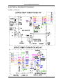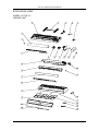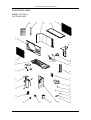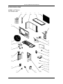
1
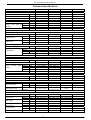
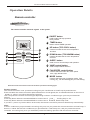
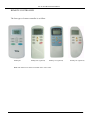
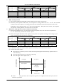
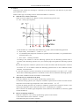
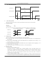
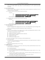
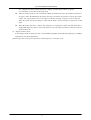
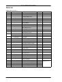
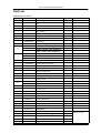
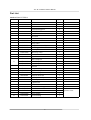
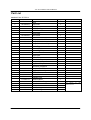
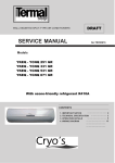
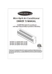
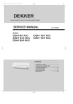
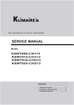
OB207t-1qxp
25/9/97 8:51 PM
Page 1
TCL
WALL MOUNTED SPLIT-TYPE AIR CONDITIONERS
SERVICE MANUAL
No.TE080528
Models
KFTHP-12
KFTHP-18
KFTHP-24
CONTENTS
1.
2.
3.
4.
5.
6.
IMPORTANT NOTICE
···································2
TECHNICAL SPECIFICATION
·····················3
OPERATION DETAILS·······································4
ELECTRICAL SCHEMATIC DIAGRAM ·········· 13
EXPLOSION VIEW
····························16
PARTS LIST
·············22
TCL Air Conditioner Service Manual
IMPORTANT NOTICE
This service manual is intended for use by individuals possessing adequate
backgrounds of electrical, electronic and mechanical experience. It is
to be installed and service by a licensed HVAC technician. Any
attempt to repair the appliance may result in personal injury and property
damage. The manufacturer or seller cannot be responsible for the
interpretation of this information, nor can it assume any liability in
connection with its use.
The information, specifications and parameter are subject to change due to
technical modification or improvement without any prior notice. The
accurate specifications are presented on the nameplate label.
How to order spare parts
To have your order filled promptly and correctly, please furnish the
following information:
1. Model No. with Indoor or Outdoor
2. No. in the Explosion View
3. Part Name
4. The quantity you ordered
2
TCL Air Conditioner Service Manual
Technical Specifications
Model No.
Type
Control type
Rated cooling capacity
Rated heating capacity
SEER
HSPF
Moisture removal
Indoor noise
cooling
level
at
High
Med.
Low
Outdoor sound power level
Electrical Data
Power supply
Cooling
Rated input
rotating
Connecting wiring
Drainage pipe
Others
Suitable area
Net dimensions
(W x H x D)
Net weight
Packing dimensions
(W x H x D)
Gross weight
Loading Capacity
208-230V
208-230V
4.6
6.7
9.7
A
4.6
6.4
9.7
1000
1550
2050
Heating
W
1000
1500
2050
Gram
A
m3/h
Cooling
Heating
Dry
Sleep
Indoor fan motor output
Outdoor air circulation
Outdoor fan type
Outdoor fan speed
Outdoor fan motor output
Connections
Refrigerant coupling
Connecting pipe
208-230V
A
W
Type
Model
LRA
MFG
speed
V
Cooling
Expansion device
Defrosting system
Fan System
Indoor air circulation/Hi
Indoor fan type
Motor
H/M/L
KFTHP-24
Heating pump
Remote
24000
23500
13.0
8.5
2.0
57
55
52
59
Heating
Refrigerating System
Refrigerant/Charge
Compressor
KFTHP-18
Heating pump
Remote
18000
17300
13.3
8.1
1.5
56
54
50
54
60Hz/1P
Voltage range
Rated current
Btu/h
Btu /h
Btu/W.h
Btu/W.h
Liters/h
dB(A)
dB(A)
dB(A)
dB(A)
KFTHP-12
Heating pump
Remote
12500
12000
13.1
8.8
1.2
42
40
38
52
rpm
rpm
rpm
rpm
W
m3/h
rpm
W
Gas
Inches
Liquid
Inches
Size
×
Core
number
Indoor
Outdoor
Indoor
Outdoor
Indoor
Outdoor
Indoor
Outdoor
40’/40’HC
m2
mm
mm
kg
kg
mm
mm
kg
kg
R410A
Rotary
---------------------------------------
700/730
Cross flow
1330/1150/950
1330/1150/950
1080
1080
20
--Propeller fan
860
31
3/8'' (9.52)
1/4'' (6.35)
3×1.5; 2×0.75
15~23
898×280×202
760×552×256
11
34
995×365×298
863×605×376
14
37
------
3
R410A
R410A
Rotary
Rotary
-------------------------------------------------------------------------------Capillary tube
Microcomputer controlled reverse system
950/1000
Cross flow
1550/1230/1110
1550/1230/1110
1100
1100
60
--Propeller fan
750
76
1400/1450
Cross flow
1550/1230/1110
1550/1230/1110
1100
1100
54
---Propeller fan
860
150
Flare type
1/2'' (12.7)
5/8'' (15.88)
1/4'' (6.35)
3/8'' (9.52)
3×1.5; 2×0.75
3×2.5
2×0.2(2×0.33)
O.D 16mm
20~35
1033×313×202
902×660×307
14
47
1103×395×292
1027×705×433
17
54
------
30~50
1250×325×245
900×800×360
22
59
1317×422×338
1031×925×447
26
65
------
TCL Air Conditioner Service Manual
Operation Details
1 Remote controller
Remote controller
The remote controller transmits signals to the system.
1 ON/OFF button
Used to start and stop operation
when pressed.
2
SLEEP TIMER ON TMIER OFF
FEEL
COOL
DRY
FAN
HEAT
AUTO
HIGH
MID
LOW
SWING
3
3
5
SLEEP
FAN
7
2
TIMER
SWING
6
ON/OFF
1
8
MODE
TIMER button
Used to select TIMER operation.
UP button (TOO COOL button)
Used to increase the set room temperature
and time.
4
DOWN button (TOO WARM button)
Used to decrease the set room temperature
and time.
5
SLEEP button
Used to set or cancel sleep mode operation.
4
6
7
VANE control button
Used to adjust airflow direction.
FAN SPEED control button
Used to select the indoor fan motor speed:
Auto, High, Mid and Low.
8
MODE button
Used to select the type of operation mode: Feel,
Cooling, Dry, Fan and Heating(Only for Heat Pump).
Note: Each mode and relevant function will be further specified in following pages.
Remote Control
The remote controller is not preset as Cooling Only Air Conditioner or Heat Pump by manufacturer.
Each time after the remote controller replace batteries or is energized, the arrowhead will flash on the front of
Heat or Cool on LCD of the remote controller.
User can preset the remote controller type depending on the air conditioner type you have purchased as
follows:
Press any button when the arrowhead flashes on the front of Cool
, Cooling Only is set.
Press any button when the arrowhead flashes on the front of
Heat , Heat Pump is set.
If you don t press any button within 10 seconds, the remote controller is preset as Heat Pump automatically.
Note :
If the air conditioner you purchased is a Cooling Only one, but you preset the remote controller as Heat Pump, it
doesn t matter. But if the air conditioner you purchased is a Heat Pump one, and you preset the remote
controller as Cooling Only, then you CAN NOT preset the Heating operation with the remote controller.
4
TCL Air Conditioner Service Manual
REMOTE CONTROLLER
The four types of remote controller is as follow:
GYKQ-05
GYKQ-10e (optional)
GYKQ-11e (optional)
Note: The function of remote controller above is the same.
5
GYKQ-12e (optional)
TCL Air Conditioner Service Manual
Electronic Controller
1.
Safety Control
(1) Time Delay Safety Control
3 minutes delay for compressor---The compressor is ceased for 3minutes to balance the pressure in the
refrigeration cycle in order to protect the compressor.
2 minutes delay for 4-way valve---The 4-way valve is ceased for 2 minutes to prevent the
refrigerant-gas abnormal noise when the HEATING operation is OFF or switch to the other operation
mode.
(2) Indoor Pipe Temperature Sensor Frost Prevention Control
When the indoor pipe temperature sensor reads 32℉ or below for 5 minutes, the indoor pipe temperature
sensor frost prevention control starts. The compressor and outdoor fan stop and indoor fan operates at high
speed for 3 minutes. After that, if the indoor pipe temperature sensor reads less than 41℉ this control
prolonged until the indoor pipe temperature sensor reads 41℉ or more.
(3) High Temperature Protection Control
During HEATING operation, the outdoor fan motor and compressor are controlled by the indoor pipe
temperature to prevent the high temperature of compressor.
Outdoor fan OFF: when the indoor pipe temperature is ≥122℉
Outdoor fan ON: when the indoor pipe temperature is ≤118.4℉
Compressor OFF: when the indoor pipe temperature is ≥143.6℉
Compressor ON: when the indoor pipe temperature is ≤118.4℉
2.
“I Feel” Mode Operation
(1) When the “I Feel” mode is selected, the operation mode and initial set temperature are determined by the
initial room temperature at start-up of the operation except to turn off the air conditioner and operates it
again.
(2) If the mode is change to “I Feel” mode from other mode, the “I Feel” mode doesn’t operate until compressor
stop for more than 3 minutes.
Mode
Initial room temperature
Initial set temperature
COOLING
78.8℉ or more
75.2℉
DRY
68℉ to 77℉
64.4℉
HEATING for Heat Pump Type
Less than 68℉
73.4℉
FAN for Cooling Only Type
In the “I Feel” mode , when the controller receives the up or down single of temperature, the set
temperature can adjust by 33.8℉ upper or lower. The biggest you can adjust by 35.6℉ upper or lower.
3.
“COOLING” Mode Operation
(1) When the COOLING mode is selected without setting temperature, the system will set the set temperature at
78.8℉ automatically with the AUTO FAN speed.
(2) When selecting the COOLING mode operation, the system will operate according to the setting by the
remote controller and the operation is as following:
6
TCL Air Conditioner Service Manual
Room Temp.
Set TEMP. +1.8℉
Set TEMP. -1.8℉
Time
4.
More than 2 min
More than 2 min
More than 2 min
More than 2 min
More than 2 min
Indoor Fan
Set Speed
Set Speed
Set Speed
Set Speed
Set Speed
Compressor
ON
OFF
ON
OFF
ON
Outdoor Fan
ON
OFF
ON
OFF
ON
“DRY” Mode Operation
(1) The system for DRY operation used the same refrigerant circle as the cooling circle.
(2) When the system operates in DRY mode ,at first it operates in cooling mode at 60.8℉ or 64.4℉ for 3 minutes.
And then, the system operates in cooling mode with low speed that regards the temperature of the room
temperature sensor reads decrease 35.6℉ as the set temperature. During the course of this, the fan speed
set operation is failing but the vane motor can be controlled.
5. “HEATING” Mode Operation (Only available for Heat Pump)
(1) When the HEATING mode is selected without setting temperature, the system will set the temperature at
73.4℉ automatically with the AUTO FAN speed.
(2) When selecting the HEATING mode operation, the system will operate according to the setting by the
remote controller and the operation is as following:
Set Temp. +1.8℉
Set Temp. -1.8℉
Room Temp.
Time
More than 2 min
More than 2 min
More than 2 min
More than 2 min
More than 2 min
Compressor
ON
OFF
ON
OFF
ON
Outdoor fan
ON
OFF
ON
OFF
ON
(3) In HEATING mode, the indoor fan motor speed is controlled by Cold Air Prevention Control.
(4) Cold Air Prevention Control
The function is intend to prevent cold air from being discharged when the heating operation starts or
when defrosting.
The indoor fan speed will be controlled as following.
The vane angle is at the angle C(100°).
Set Speed
9 3 . 2℉
Low Speed
80.6℉
Low Speed
Temperature drop
Temperature raise
Set Speed
7 7℉
Stop the fan
73.4℉
Stop the fan
During the heating operation, if the compressor stops that it will adjust the indoor fan speed, after 30
seconds to stop the fan.
7
TCL Air Conditioner Service Manual
(5) Defrost
Defrosting of the outdoor heat exchange is controlled by the microprocessor with detection by the indoor
pipe temperature sensor.
Defrost control type is according to the JC on the PCB whether is connected.
When the JC is connect on the PCB
When one of the conditions of A, Band C is satisfy, the defrosting operation stars.
A.
IPT--- indoor pipe temperature
℉)
In the condition A, it must satisfy the conditions a), b)and c) then into defrosting operation.
a) IPT1 satisfy IPT1=IPTMAX-△IPT(14.4℉)
b) t5≥50minutes(the compressor cumulative operation time≥50 minutes, t5 is permitted move
and lower than t1 too).
c) IPT<104℉,and keep 2 minutes.
According to the condition A enter the defrosting operation, the first defrosting operation time is
8 minutes; After defrosting operation one cycle, and then judge and regulate the defrosting operation
time.
B. After the compressor cumulative operation time exceeds 120 minutes and the temperature of the IPT
is less than 95℉ for 2 minutes. When the defrosting operation time on this condition exceeds
8 minutes, it will terminate.
C. After the compressor operates continuously for 20 minutes and the IPT is less than 73.4℉ or from
the last time of defrosting operation is 50 minutes or more interval. When the defrosting operation
time on this condition exceeds 10 minutes, it will terminate.
When the JC isn’t connected on the PCB
When the conditions of a) or b) is satisfy, the defrosting operation starts.
a) Under the heating operation, the compressor cumulative operation time exceeds 50 minutes and the
temperature of the outdoor pipe temperature sensor reads lower than -14.4℉
b) Under the heating operation, the compressor cumulative operation time exceeds 50 minutes, if the
indoor pipe temperature sensor reads lower than 104℉ continuously for 2 minutes.
Note: If haven’t the outdoor pipe temperature sensor that uses the condition b) to defrost, against
use the condition a).
Defrost terminating conditions
When the condition c) or d) is satisfy, the defrosting operation will terminate.
c) The outdoor defrost sensor reads 68℉ or more.
d) The defrosting time exceeds 10 minutes.
8
TCL Air Conditioner Service Manual
Defrosting time chart
Outdoor Fan
ON
Revering Valve
OFF
ON
Compressor Relay
ON
OFF
OFF
39S
6.
ON
ON
ON
5S
OFF
Defrost Count MAX 12min
19S
15S
ON
t
“FAN” mode operation
The indoor fan motor always turns on at the set speed and the vane motor turns on at the set fettle.
7.
4-way Valve control
HEATING
ON
COOLING/DRY
OFF
The 4-way valve reverses for 5 seconds right before start-up of the compressor as following chart:
COOLING/DRY TO HEATING
HEATING TO COOLING/DRY
Compressor
4-way Valve
5s
2min
Outdoor Fan
8.
“SLEEP” mode
When the SLEEP button is pressed, the SLEEP mode is selected as following:
The indoor fan speed is set at the low speed, the power lamp and the sleep lamp is on, the temperature off
after 5 minutes.
When selecting COOLING/DRY operation with SLEEP mode, the set temperature will be raised by 1.8℉ 1
hour later and by 3.6℉ 2 hour later.
When selecting HEATING operation with SLEEP mode, the set temperature will be dropped by 1.8℉ 1
hour later and 3.6℉ 2 hour later.
After the System operates in SLEEP mode for 8 hours, it will stop automatically.
9.
Fan motor control
(1) Rotational frequency feedback control
The indoor fan motor is equipped with a rotational frequency sensor, and outputs signal to the
microprocessor to feedback the rotational frequency. Comparing the current rotational frequency with the
target rotational frequency, the microprocessor adjusts fan motor electric to make the current rotational
frequency close to the target rotational frequency. With this control, when the fan speed is switched, the
rotational frequency changes smoothly.
(2) When the rotational frequency feedback signal has not output for 5 seconds (or when the microprocessor
can’t detect the signal for 5 seconds), the fan motor is regarded locked-up. Then the electric current to the fan
9
TCL Air Conditioner Service Manual
motor is shut off. 10 seconds later, the electric current is applied to the fan motor again. During the fan motor
lock-up, the POWER indicator lamp flashes on and off 6times/cycle or E6 to show the fan motor
abnormality.
10. Auto Fan Speed Control
(1) When the auto fan speed is selected, the indoor fan motor speed is automatically controlled by the room
temperature and the set temperature.
(2) In COOLING mode, the indoor fan motor operates as following:
Fan Speed
Hi
Me
Lo
Room temperature minus set temperature:
1.8℉ 3.6℉ 7.2℉
(3) In HEATING mode, the indoor fan motor operates as following;
Fan Speed
Hi
Mi
Lo
Room temperature minus set temperature
1 .8℉ 3.6℉ 7.2℉
11. Auto Vane Operation control
(1) Vane motor drive
The unit is equipped with a stepping motor for the vane. The rotating direction, speed, and angle of the
motor are controlled by pulse signal transmitted from indoor microprocessor.
(2) Positioning
The vane is once pressed to the vane stopper below to confirm the standard position and then set to the
desired angle. The positioning is decided as follows:
When the ON/OFF button is pressed.
When the vane control is change from AUTO to MANUAL.
When the SWING is finished.
When the test run starts.
When the power supply turns ON.
(3) The auto vane changes as follows by pressing the VANE CONTROL button.
(4) VANE AUTO mode
In vane auto mode, the microprocessor automatically determines the vane angle and operation to make the
optimum room-temperature distribution.
(5) SWING mode
When presses the SWING button, the vane swings.
12. TIMER Operation
(1) To activate the air conditioner at the desire time, follow the procedure specified below(the remote control
and air conditioner are switched off):
Press the Timer button.
Select the desired mode by pressing the Mode button.
Select the desired temperature by pressing the ▲ ▼ button(only possible when the ‘cool’ or ‘heat’
mode is selected).
Select the ventilator speed (low, medium or high) or automatic mode(only possible when the feel, Cool
or Heat mode is selected) by pressing the Fan button.
The ventilator always operates in the Auto mode when the Dry mode is selected.
Select Swing or no Swing by pressing the Swing button.
10
TCL Air Conditioner Service Manual
Press the Timer button(‘h’ flashes).
Use the ▲▼ button to select the time at which the air conditioner must activate (between 0 and 10
hours can be set at every half hour-between 10 and 24 hours can be set at every hour).
Press the Timer button (‘h’ stops flashing) and the preset time appears in the display.
Press the Timer button again to delete the selected data from the memory.
Note : If no buttons are pressed during the programming of the timer function, thee remote control will
switch off automatically after 10 seconds.
(2) To switch the air conditioner off at the desired time, follow the procedure specified below (the remote control
and air conditioner are switched off):
Press the timer button.
Use the ▲▼ button to select the time at witch.
13. EMERGENCY Operation
When the EMERGENCY Operation switch is pressed once, COOLING mode is selected and if in 3 seconds the
EMERGENCY Operation switch is pressed again, mode is selected. Then pressed once again, the unit is switch
off.
When the remote controller is missing, has failed or the batteries run down, press the EMERGENCY Operation
switch on the front of the indoor unit. The unit will start.
The first 30 minutes of operation will be the test run operation. The operation is for servicing. The indoor fan runs
at high speed and the system is in continuous operation. The thermostat is ON and the timer is reset to normal.
After 30 minutes of test run operation the system shifts to AUTO COOLING/HEATING mode, and the indoor fan
runs in automatic speed. The operation continues unit the EMERGENCY operation switch is pressed or a button
on the remote controller is pressed and normal operation will start.
NOTE: Do not press the EMERGEMCY Operation switch during normal operation.
14.
AUTO RESTART Function(Option)
1.When the indoor unit is controlled with the remote controller, the operation mode, set temperature, and the fan
speed are memorized by the indoor electric control PCB. The AUTO RESTART function sets to work the
moment power has restored after power failure. Then, the unit will restart automatically.
2. How to set the AUTO RESTAR function.
Press the emergency switch and power supply to the PCB following, hold 10 seconds and the buzzer will
beep three times. The AUTO-RESTAR is set.
Do the operation again, the buzzer will beep four times and the AUTO-RESTAR function is cancelled.
15. Failure Display and Handling
a)
Failure Display
When the controller has failure, the buzzer will sound long for three times, and displays the failure from the
failure lamp.
b)
Failure Code
If have the digital pipe that displays the failure code for digital pipe, or display for the run lamp.
c)
Type of failure
The lamp flash
Display of digital pipe
The failure of room temperature sensor
Once/cycle
E1
The failure of indoor pipe temperature sensor
Twice/cycle
E2
The failure of indoor fan motor
6 times/cycle
E6
Failure Handling
When the room temperature sensor or the indoor pipe temperature sensor has a failure, the system will be
shut off, the compressor will be OFF, and the outdoor fan and the indoor fan will be OFF. The system
doesn’t receive the signal of remoter controller except the signal of shut off it. When the failure
disappear, the controller can operate in normal mode. before this, presses the “ON/OFF” to start the
system, and it will operate in COOLING or HEATING for 30 minutes, and follows shut off. During
11
TCL Air Conditioner Service Manual
this, it displays the failure and the protection is failing. You must power off/on to operate
it. In the failure, you can operate the FAN mode.
When the outdoor protects in the COOLING or DRY, the outdoor unit stops, the indoor fan operates in
set speed ; and in the HEATING, the outdoor unit stops, the indoor fan operates in cold air prevention
control. The system doesn’t receive the signal of remoter controller except the signal of shut off.
When the system checks the voltage is 220V and the delay control is finished, it operates at normal
again.
When the indoor fan motor is failure, the compressor is stopped, the outdoor fan and indoor fan is
stopped and display the failure. The system doesn’t receive the signal of remoter controller except the
signal of shut it off.
d)
Display Of The Control
In the display board the lamp from left is the POWER lamp(Red), the SLEEP lamp(Yellow), the TIMER
lamp(Yellow), the RUN lamp(Green).
g) When it gives the control power, the buzzer sounds long for 0.3 second per cycle.
12
TCL Air Conditioner Service Manual
ELECTRICAL SCHEMATIC DIAGRAM
MODEL: KFTHP-12
θ
13
TCL Air Conditioner Service Manual
ELECTRICAL SCHEMATIC DIAGRAM
MODEL: KFTHP-18
14
TCL Air Conditioner Service Manual
ELECTRICAL SCHEMATIC DIAGRAM
MODEL: KFTHP-24
θ
15
TCL Air Conditioner Service Manual
EXPLOSION VIEW
MODEL: KFTHP-12
INDOOR UNIT
16
TCL Air Conditioner Service Manual
EXPLOSION VIEW
MODEL: KFTHP-18
INDOOR UNIT
4
3
2
1
5
6
7
8
28
9
10
27
11
26
12
13
25
14
15
24
23
16
22
21
17
20
18
19
17
TCL Air Conditioner Service Manual
EXPLOSION VIEW
MODEL: KFTHP-24
INDOOR UNIT
4
3
2
1
5
6
31
7
30
8
29
9
28
10
27
11
12
26
13
25
14
15
24
23
16
22
21
17
20
18
19
18
TCL Air Conditioner Service Manual
EXPLOSION VIEW
MODEL: KFTHP-12
OUTDOOR UNIT
5
4
3
2
1
6
27
7
26
8
25
9
24
23
10
22
11
21
20
19
12
18
13
14
15
19
16
17
TCL Air Conditioner Service Manual
EXPLOSION VIEW
MODEL: KFTHP-18
OUTDOOR UNIT
5
4
3
2
1
6
28
7
27
8
26
9
25
24
23
10
22
11
21
20
19
12
18
13
14
15
20
16
17
TCL Air Conditioner Service Manual
EXPLOSION VIEW
MODEL: KFTHP-24
OUTDOOR UNIT
5
4
3
2
1
6
28
7
27
8
26
9
25
24
23
10
22
11
21
20
19
12
18
13
14
15
21
16
17
TCL Air Conditioner Service Manual
Part List
Indoor Unit- KFTHP-12
No.
Part No.
1
1170240001
2
1170230001
3
1070350245
4
1080030021
5
1070350243
6
1070020024
7
1070100010
8
1090020030
9
10
1170030065
1070350152
11
1070350119
12
1090500224
13
1070350235
14
1070040005
1070040006
15
16
17
1110050903
1070350137
1070350140
18
1070110011
19
1070350155
20
1170020011
21
1070500250
22
1070190012
23
1070450115
24
25
1071990048
1070500246
26
1070350135
27
1070190013
28
1090500118
29
30
31
32
33
34
1070250425
1090050318
1070060003
1190470001
1190060054
1190060055
Part Name
Transformer
Indoor Sensor Assembly
In And Out Pipe Fixer
Installation Plate
Base
Cross Fan
Bearing Mount
Heater
Indoor Motor
Indoor Motor Cover
Electrical Box
Main PCB
Electrical Box Cover
Cable Clamp Base
Cable Clamp Cover
Evaporator
Water Drainage Assembly
Vane
Drainage Hose
Evaporator Fastness Clamp
Vane Motor
Face Frame
Left Air Filter
Front Panel
Display PCB Cover
Servicing Cover
Screw Cover
Right Air Filter
Display PCB
Display PCB Box
Remote Controller
Remote Controller Supporter
Indoor Carton
Left Foaming
Right Foaming
22
Q’ty
1
Remark
1
1
1
1
1
1
1
1
1
1
1
1
1
1
1
12
1
1
1
1
1
1
1
1
1
3
1
1
1
1
1
1
1
1
Not shown in
Explosion view
TCL Air Conditioner Service Manual
Part List
Indoor Unit- KFTHP-18
No.
Part No.
1
1080030001
2
1213090101
3
1070020014
4
1070100010
5
1170030075
6
1073090120
7
1170020011
8
1083090108
9
1110050896
10
1213090102
11
1073090105
12
1073090106
1073090107
13
1070110011
14
1170230001
15
1173090107
16
1070500692
17
1070500502
18
1091990054
19
1073090126
20
1090500501
21
1073090108
1073090125
22
1073090112
1073090113
23
1073090111
24
1070500312
25
1073090114
26
1090700209
27
1073090121
28
1070500008
29
1090050318
30
1070060003
31
1190060003
32
1190060019
33
1190060020
34
1190060002
35
1190060021
Part Name
Installation Plate
Base
Cross Fan
Bearing Mount
Indoor Motor
Indoor Motor Clamp
Vane Motor
Clip Base
Evaporator
Water Drainage Assembly
Vertical Vane Supporter
Vertical Vane A
Vertical Vane B
Drainage Hose
Indoor Sensor Assembly
Transformer
Front Panel
Display PCB Cover
Heater
Display PCB Box
Display PCB
Vane A
Vane B
Left Air Filter
Right Air Filter
Screw Cover
Face Frame
Electrical Box Cover
Main PCB
Electrical Box
Breakwater
Remote Controller
Remote Controller Supporter
Indoor Carton
Left Foaming
Right Foaming
Middle Pasteboard Supporter
Middle Foaming Supporter
23
Q’ty
1
1
1
1
1
1
2
1
1
1
1
14
2
1
1
1
1
1
1
1
1
1
1
1
1
3
1
1
1
1
1
1
1
1
1
1
1
1
Remark
Not
shown
Explosion view
in
TCL Air Conditioner Service Manual
Part List
Indoor Unit- KFTHP-24
No.
Part No.
1
1080030017
2
1070850102
3
1070020021
4
1070100014
5
1170030076
6
1070850133
7
1170020023
8
1070850140
9
1110050894
10
1210850106
1070850114
1070850116
11
1070850119
1070850121
1070850122
12
1070850123
13
1070110012
14
1170230001
15
1173090107
16
1070850257
17
1070850148
18
1091990055
19
1070850145
20
1090500501
1070850107
21
1070850108
22
1070850131
23
1070850130
24
1070850126
25
1070850219
26
1090850117
27
1070850132
28
1070850133
29
1070850218
30
1070850103
31
1070850135
32
1090050318
33
1070060003
34
1190040008
35
1190070037
36
1190070038
Part Name
Installation Plate
Base
Cross Fan
Bearing Mount
Indoor Motor
Indoor Motor Clamp
Vane Motor
Clip Base
Evaporator
Water Drainage Assembly
Left Vertical Vane Supporter
Middle Vertical Vane Supporter
Right Vertical Vane Supporter
Large Vertical Vane
Middle Vertical Vane
Small Vertical Vane
Drainage Hose
Indoor Sensor Assembly
Transformer
Front Panel
Display PCB Cover
Heater
Display PCB Box
Display PCB
Up Vane
Down Vane
Air Filter
Screw Cover
Face Frame
Electrical Box Cover
Main PCB
Indoor Motor Base
Indoor Motor Cover
Electrical Box
In And Out Pipe Fixer
Breakwater
Remote Controller
Remote Controller Supporter
Indoor Carton
Base Foaming
Upper Foaming
24
Q’ty
1
Remark
1
1
1
1
1
2
1
1
1
1
1
1
16
2
2
1
1
1
1
1
1
1
1
1
1
2
3
1
1
1
1
1
1
1
1
1
1
1
1
1
Not
shown
Explosion view
in
TCL Air Conditioner Service Manual
Part List
Outdoor Unit- KFTHP-12
No.
Part No.
1
1400250857
2
1080050011
3
1110060867
4
1080050001
5
1080050007
6
1080050009
7
1080320112
8
1210250121
9
1100060092
10
1120500226
11
1120250561
12
1080050003
13
1120120021
14
1120130036
15
1081990107
16
1080050002
17
18
19
20
21
22
23
24
1070040001
1070040003
1070040008
1171990049
1170100004
1080010006
1170100032
1080020001
1120350781
27
1080170001
1070030016
1170040064
1080050004
28
29
30
31
1190070020
1190070002
1190070022
1190070021
25
26
Part Name
Grille
Top Cover
Condenser
Left Grille Supporter
Left Grille
Front Plate
Fan Guard
Base
Compressor And It Accessories
4-way Valve
4-way Valve Assembly
Valve Supporter
Two-way Valve
Three-way Valve
Electrical Box Cover
Right Plate
Cable ClampФ6
Cable ClampФ8
Cable ClampФ10
Terminal
Compressor Capacitor
Capacitor Strip
Fan Motor Capacitor
Electrical Parts Box
Capillary Assembly
Partition plate
Propeller Fan
Outdoor Motor
Outdoor Motor Supporter
Base Carton
Cabinet Carton
Base Foaming
Cover Forming
25
Q’ty
1
1
1
1
1
1
1
1
1
1
1
1
1
1
1
1
1
1
1
1
1
1
1
1
1
1
1
1
1
1
1
1
1
Remark
Not shown in the
Explosion view.
TCL Air Conditioner Service Manual
Part List
Outdoor Unit- KFTHP-18
No.
Part No.
1
1071990041
2
1081990038
3
1110061027
4
1081990040
5
1081990045
6
1081990047
7
1081990048
8
1081990052
9
1100060093
10
1120500226
11
1120500853
12
1081990041
13
1120120021
14
1120130032
15
1081990107
16
1081990039
17
1074060118
18
1171990049
19
1170100026
20
1080010006
21
1170100030
22
1081990049
23
1120500852
24
1174561801
25
1141990004
26
1070030025
27
1170040112
28
1081990042
29
1190060191
30
1190500707
31
1190060190
32
1190070052
Part Name
Grille
Top Cover
Condenser
Left Grille Supporter
Left Grille
Front Plate
Fan Guard
Base
Compressor And It Accessories
4-way Valve
4-way Valve Assembly
Valve Supporter
Two-way Valve
Three-way Valve
Electrical Box Cover
Right Plate
Cable Clamp
Terminal
Compressor Capacitor
Capacitor Strip
Fan Motor Capacitor
Electrical Parts Box
Capillary Assembly
AC Contactor
Sound Insulation
Propeller Fan
Outdoor Motor
Outdoor Motor Supporter
Base Carton
Cabinet Carton
Base Foaming
Cover Forming
26
Q’ty
1
1
1
1
1
1
1
1
1
1
1
1
1
1
1
1
1
1
1
1
1
1
1
1
1
1
1
1
1
1
1
1
Remark
Not
shown
in
Explosion view.
the
TCL Air Conditioner Service Manual
Part List
Outdoor Unit- KFTHP-24
No.
Part No.
1
1071990055
2
1080050045
3
1110061030
4
1080050042
5
1080050046
6
1080050047
7
1080050048
8
1080110001
9
1100200008
10
1120110017
11
1120700527
12
1080050044
13
1120120037
14
1120130047
15
1081990107
16
1080050043
17
1074060118
18
1171990049
19
1170100007
20
1080010004
21
1170100029
22
1080050056
23
1120700526
24
1174561801
25
1140020003
26
1070030023
27
1170040115
28
1080050050
29
1190430001
30
1170230005
31
1190070041
Part Name
Grille
Top Cover
Condenser
Left Grille Supporter
Left Grille
Front Plate
Fan Guard
Base
Compressor And It Accessories
4-way Valve
4-way Valve Assembly
Valve Supporter
Two-way Valve
Three-way Valve
Electrical Box Cover
Right Plate
Cable Clamp
Terminal
Compressor Capacitor
Capacitor Strip
Fan Motor Capacitor
Electrical Parts Box
Capillary Assembly
AC Contactor
Sound Insulation
Propeller Fan
Outdoor Motor
Outdoor Motor Supporter
Cabinet Carton
Outdoor Sensor
Cover Forming
27
Q’ty
1
1
1
1
1
1
1
1
1
1
1
1
1
1
1
1
1
1
1
1
1
1
1
1
1
1
1
1
1
1
1
Remark
Not shown in the
Explosion view.